

Page 1
Symbol DS9808 Digital Scanner
Product Reference Guide
Page 2

Page 3

Symbol DS9808 Digital Scanner
Product Reference Guide
72E-112999-02
Revision A
May 2009
Page 4

ii Symbol DS9808 Product Reference Guide
© 2009 by Motorola, Inc. All rights reserved.
No part of this publication may be reproduced or used in any form, or by any electrical or mechanical means,
without permission in writing from Motorola. This includes electronic or mechanical means, such as
photocopying, recording, or information storage and retrieval systems. The material in this manual is subject to
change without notice.
The software is provided strictly on an “as is” basis. All software, including firmware, furnished to the user is on
a licensed basis. Motorola grants to the user a non-transferable and non-exclusive license to use each
software or firmware program delivered hereunder (licensed program). Except as noted below, such license
may not be assigned, sublicensed, or otherwise transferred by the user without prior written consent of
Motorola. No right to copy a licensed program in whole or in part is granted, except as permitted under
copyright law. The user shall not modify, merge, or incorporate any form or portion of a licensed program with
other program material, create a derivative work from a licensed program, or use a licensed program in a
network without written permission from Motorola. The user agrees to maintain Motorola’s copyright notice on
the licensed programs delivered hereunder, and to include the same on any authorized copies it makes, in
whole or in part. The user agrees not to decompile, disassemble, decode, or reverse engineer any licensed
program delivered to the user or any portion thereof.
Motorola reserves the right to make changes to any software or product to improve reliability, function, or
design.
Motorola does not assume any product liability arising out of, or in connection with, the application or use of
any product, circuit, or application described herein.
No license is granted, either expressly or by implication, estoppel, or otherwise under any Motorola, Inc.,
intellectual property rights. An implied license only exists for equipment, circuits, and subsystems contained in
Motorola products.
MOTOROLA and the Stylized M Logo and Symbol and the Symbol logo are registered in the US Patent &
Trademark Office. Bluetooth is a registered trademark of Bluetooth SIG. Microsoft, Windows and ActiveSync
are either registered trademarks or trademarks of Microsoft Corporation. All other product or service names
are the property of their respective owners.
Motorola, Inc.
One Motorola Plaza
Holtsville, New York 11742-1300
http://www.motorola.com/enterprisemobility
Patents
This product is covered by one or more of the patents listed on the website:
http://www.motorola.com/enterprisemobility/patents.
Warranty
For the complete Motorola hardware product warranty statement, go to:
http://www.motorola.com/enterprisemobility/warranty.
Page 5

Revision History
Changes to the original manual are listed below:
Change Date Description
-01 Rev A 03/2009 Initial release
-02 Rev A 05/2009 Update to correct revision errors
iii
Page 6

iv Symbol DS9808 Product Reference Guide
Page 7

Table of Contents
About This Guide
Introduction.................................................................................................................... xiii
Configurations................................................................................................................ xiii
Chapter Descriptions ..................................................................................................... xiv
Notational Conventions.................................................................................................. xv
Related Documents ....................................................................................................... xv
Service Information........................................................................................................ xvi
Chapter 1: Getting Started
Introduction ................................................................................................................... 1-1
Interfaces ...................................................................................................................... 1-2
Unpacking ..................................................................................................................... 1-2
Setting Up the Digital Scanner ...................................................................................... 1-3
Installing the Interface Cable .................................................................................. 1-3
Connecting Power (if required) ............................................................................... 1-4
Configuring the Digital Scanner .............................................................................. 1-4
Mounting the Digital Scanner ....................................................................................... 1-4
Accessories .................................................................................................................. 1-5
Required Accessories ............................................................................................. 1-5
Optional Accessories .............................................................................................. 1-5
Electronic Article Surveillance (EAS) (Optional) ........................................................... 1-5
Chapter 2: Scanning
Introduction ................................................................................................................... 2-1
Beeper Definitions ........................................................................................................ 2-2
LED Definitions ............................................................................................................. 2-4
Scanning ....................................................................................................................... 2-5
Hands-Free Scanning ............................................................................................. 2-5
Hand-Held Scanning ............................................................................................... 2-5
Aiming ..................................................................................................................... 2-6
Decode Ranges ............................................................................................................ 2-8
Page 8

vi Symbol DS9808 Product Reference Guide
Chapter 3: Maintenance & Technical Specifications
Introduction ................................................................................................................... 3-1
Maintenance ................................................................................................................. 3-1
Troubleshooting ............................................................................................................ 3-2
Technical Specifications ............................................................................................... 3-5
Digital Scanner Signal Descriptions .............................................................................. 3-7
Chapter 4: User Preferences & Miscellaneous Digital Scanner Options
Introduction ................................................................................................................... 4-1
Scanning Sequence Examples ..................................................................................... 4-2
Errors While Scanning .................................................................................................. 4-2
User Preferences/Miscellaneous Options Parameter Defaults ..................................... 4-2
User Preferences .......................................................................................................... 4-4
Set Default Parameter ............................................................................................ 4-4
Parameter Bar Code Scanning ............................................................................... 4-5
Beep After Good Decode ........................................................................................ 4-5
Beeper Tone ........................................................................................................... 4-6
Beeper Volume ....................................................................................................... 4-7
Beeper Duration ...................................................................................................... 4-8
Hands-Free Mode ................................................................................................... 4-9
Presentation Performance Mode ............................................................................ 4-9
Digital Scanner Activity Modes ............................................................................... 4-10
Hand-Held Trigger Mode ........................................................................................ 4-18
Multifunction Mode Triggering (DS9808-LR/LL Only) ............................................. 4-19
Host Triggering (DS9808-LR/LL Only) .................................................................... 4-24
Picklist Mode ........................................................................................................... 4-26
Continuous Bar Code Read .................................................................................... 4-27
Decode Session Timeout ........................................................................................ 4-27
Timeout Between Decodes, Same Symbol ............................................................ 4-28
Timeout Between Decodes, Different Symbols ...................................................... 4-28
Fuzzy 1D Processing .............................................................................................. 4-29
Hand-Held Decode Aiming Pattern ......................................................................... 4-30
Hands-Free Decode Aiming Pattern ....................................................................... 4-31
Presentation Mode Field of View ............................................................................ 4-32
Decoding Illumination (Hand-Held Mode only) ....................................................... 4-33
Miscellaneous Scanner Parameters ............................................................................. 4-34
Transmit Code ID Character ................................................................................... 4-34
Prefix/Suffix Values ................................................................................................. 4-35
Scan Data Transmission Format ............................................................................ 4-36
FN1 Substitution Values ......................................................................................... 4-37
Scan Data Transmission Format (continued) ......................................................... 4-37
Transmit “No Read” Message ................................................................................. 4-38
Chapter 5: Imaging Preferences
Introduction ................................................................................................................... 5-1
Scanning Sequence Examples ..................................................................................... 5-2
Errors While Scanning .................................................................................................. 5-2
Imaging Preferences Parameter Defaults ..................................................................... 5-2
Page 9

Table of Contents vii
Imaging Preferences ..................................................................................................... 5-4
Operational Modes .................................................................................................. 5-4
Image Capture Illumination ..................................................................................... 5-5
Gain/Exposure Priority for Snapshot Mode ............................................................. 5-6
Snapshot Mode Timeout ......................................................................................... 5-7
Snapshot Aiming Pattern ........................................................................................ 5-7
Image Cropping ...................................................................................................... 5-8
Crop to Pixel Addresses ......................................................................................... 5-9
Image Size (Number of Pixels) ............................................................................... 5-10
Image Brightness (Target White) ............................................................................ 5-11
JPEG Image Options .............................................................................................. 5-11
JPEG Target File Size ............................................................................................ 5-12
JPEG Quality and Size Value ................................................................................. 5-12
Image Enhancement ............................................................................................... 5-13
Image File Format Selector ..................................................................................... 5-14
Bits Per Pixel ........................................................................................................... 5-15
Signature Capture ................................................................................................... 5-16
Signature Capture File Format Selector ................................................................. 5-17
Signature Capture Bits Per Pixel ............................................................................ 5-18
Signature Capture Width ......................................................................................... 5-19
Signature Capture Height ....................................................................................... 5-19
Signature Capture JPEG Quality ............................................................................ 5-19
Video View Finder ................................................................................................... 5-20
Video View Finder Image Size ................................................................................ 5-20
Chapter 6: USB Interface
Introduction ................................................................................................................... 6-1
Connecting a USB Interface ......................................................................................... 6-2
USB Parameter Defaults .............................................................................................. 6-3
USB Host Parameters .................................................................................................. 6-4
USB Device Type .................................................................................................... 6-4
Symbol Native API (SNAPI) Status Handshaking ................................................... 6-5
USB Country Keyboard Types - Country Codes ..................................................... 6-6
USB Keystroke Delay ............................................................................................. 6-8
USB CAPS Lock Override ...................................................................................... 6-8
USB Ignore Unknown Characters ........................................................................... 6-9
Emulate Keypad ...................................................................................................... 6-9
Emulate Keypad with Leading Zero ........................................................................ 6-10
USB Keyboard FN 1 Substitution ............................................................................ 6-10
Function Key Mapping ............................................................................................ 6-11
Simulated Caps Lock .............................................................................................. 6-11
Convert Case .......................................................................................................... 6-12
ASCII Character Set for USB ........................................................................................ 6-13
Chapter 7: RS-232 Interface
Introduction ................................................................................................................... 7-1
Connecting an RS-232 Interface .................................................................................. 7-2
RS-232 Parameter Defaults .......................................................................................... 7-3
Page 10

viii Symbol DS9808 Product Reference Guide
RS-232 Host Parameters .............................................................................................. 7-4
RS-232 Host Types ................................................................................................. 7-6
Baud Rate ............................................................................................................... 7-7
Parity ....................................................................................................................... 7-9
Data Bits ................................................................................................................. 7-9
Check Receive Errors ............................................................................................. 7-10
Hardware Handshaking .......................................................................................... 7-10
Software Handshaking ............................................................................................ 7-12
Host Serial Response Time-out .............................................................................. 7-14
RTS Line State ........................................................................................................ 7-15
Beep on <BEL> ....................................................................................................... 7-15
Intercharacter Delay ................................................................................................ 7-16
Nixdorf Beep/LED Options ...................................................................................... 7-17
Ignore Unknown Characters ................................................................................... 7-17
ASCII Character Set for RS-232 ................................................................................... 7-18
Chapter 8: IBM 468X / 469X Interface
Introduction ................................................................................................................... 8-1
Connecting to an IBM 468X/469X Host ........................................................................ 8-2
IBM Parameter Defaults ............................................................................................... 8-3
IBM 468X/469X Host Parameters ................................................................................. 8-4
Port Address ........................................................................................................... 8-4
Convert Unknown to Code 39 ................................................................................. 8-5
Chapter 9: Keyboard Wedge Interface
Introduction ................................................................................................................... 9-1
Connecting a Keyboard Wedge Interface ..................................................................... 9-2
Keyboard Wedge Parameter Defaults .......................................................................... 9-3
Keyboard Wedge Host Parameters .............................................................................. 9-4
Keyboard Wedge Host Types ................................................................................. 9-4
Keyboard Wedge Country Types - Country Codes ................................................. 9-5
Ignore Unknown Characters ................................................................................... 9-7
Keystroke Delay ...................................................................................................... 9-7
Intra-Keystroke Delay ............................................................................................. 9-8
Alternate Numeric Keypad Emulation ..................................................................... 9-8
Caps Lock On ......................................................................................................... 9-9
Caps Lock Override ................................................................................................ 9-9
Convert Wedge Data .............................................................................................. 9-10
Function Key Mapping ............................................................................................ 9-10
FN1 Substitution ..................................................................................................... 9-11
Send Make and Break ............................................................................................ 9-11
Keyboard Maps ....................................................................................................... 9-12
ASCII Character Set for Keyboard Wedge ................................................................... 9-13
Chapter 10: Symbologies
Introduction ................................................................................................................... 10-1
Scanning Sequence Examples ..................................................................................... 10-1
Page 11

Table of Contents ix
Errors While Scanning .................................................................................................. 10-2
Symbology Parameter Defaults .................................................................................... 10-2
UPC/EAN ...................................................................................................................... 10-7
Enable/Disable UPC-A ............................................................................................ 10-7
Enable/Disable UPC-E ............................................................................................ 10-7
Enable/Disable UPC-E1 .......................................................................................... 10-8
Enable/Disable EAN-8/JAN-8 ................................................................................. 10-8
Enable/Disable EAN-13/JAN-13 ............................................................................. 10-9
Enable/Disable Bookland EAN ............................................................................... 10-9
Decode UPC/EAN/JAN Supplementals .................................................................. 10-10
User-Programmable Supplementals ....................................................................... 10-13
UPC/EAN/JAN Supplemental Redundancy ............................................................ 10-13
UPC/EAN/JAN Supplemental AIM ID Format ......................................................... 10-14
Transmit UPC-A Check Digit .................................................................................. 10-14
Transmit UPC-E Check Digit .................................................................................. 10-15
Transmit UPC-E1 Check Digit ................................................................................ 10-15
UPC-A Preamble .................................................................................................... 10-16
UPC-E Preamble .................................................................................................... 10-17
UPC-E1 Preamble .................................................................................................. 10-18
Convert UPC-E to UPC-A ....................................................................................... 10-19
Convert UPC-E1 to UPC-A ..................................................................................... 10-19
EAN-8/JAN-8 Extend .............................................................................................. 10-20
Bookland ISBN Format ........................................................................................... 10-21
UCC Coupon Extended Code ................................................................................. 10-22
ISSN EAN ............................................................................................................... 10-22
Code 128 ...................................................................................................................... 10-23
Enable/Disable Code 128 ....................................................................................... 10-23
Set Lengths for Code 128 ....................................................................................... 10-23
Enable/Disable GS1-128 (formerly UCC/EAN-128) ................................................ 10-24
Enable/Disable ISBT 128 ........................................................................................ 10-25
ISBT Concatenation ................................................................................................ 10-26
Check ISBT Table ................................................................................................... 10-27
ISBT Concatenation Redundancy ........................................................................... 10-27
Code 39 ........................................................................................................................ 10-28
Enable/Disable Code 39 ......................................................................................... 10-28
Enable/Disable Trioptic Code 39 ............................................................................ 10-28
Convert Code 39 to Code 32 .................................................................................. 10-29
Code 32 Prefix ........................................................................................................ 10-29
Set Lengths for Code 39 ......................................................................................... 10-30
Code 39 Check Digit Verification ............................................................................ 10-31
Transmit Code 39 Check Digit ................................................................................ 10-31
Code 39 Full ASCII Conversion .............................................................................. 10-32
Code 39 Buffering - Scan & Store ........................................................................... 10-32
Code 93 ........................................................................................................................ 10-35
Enable/Disable Code 93 ......................................................................................... 10-35
Set Lengths for Code 93 ......................................................................................... 10-35
Code 11 ........................................................................................................................ 10-37
Code 11 .................................................................................................................. 10-37
Set Lengths for Code 11 ......................................................................................... 10-37
Code 11 Check Digit Verification ............................................................................ 10-39
Page 12

x Symbol DS9808 Product Reference Guide
Transmit Code 11 Check Digits .............................................................................. 10-40
Interleaved 2 of 5 (ITF) ................................................................................................. 10-40
Enable/Disable Interleaved 2 of 5 ........................................................................... 10-40
Set Lengths for Interleaved 2 of 5 ........................................................................... 10-41
I 2 of 5 Check Digit Verification ............................................................................... 10-43
Transmit I 2 of 5 Check Digit ................................................................................... 10-43
Convert I 2 of 5 to EAN-13 ...................................................................................... 10-44
Discrete 2 of 5 (DTF) .................................................................................................... 10-44
Enable/Disable Discrete 2 of 5 ................................................................................ 10-44
Set Lengths for Discrete 2 of 5 ............................................................................... 10-45
Codabar (NW - 7) ......................................................................................................... 10-47
Enable/Disable Codabar ......................................................................................... 10-47
Set Lengths for Codabar ......................................................................................... 10-47
CLSI Editing ............................................................................................................ 10-49
NOTIS Editing ......................................................................................................... 10-49
MSI ............................................................................................................................... 10-50
Enable/Disable MSI ................................................................................................ 10-50
Set Lengths for MSI ................................................................................................ 10-50
MSI Check Digits .................................................................................................... 10-52
Transmit MSI Check Digit(s) ................................................................................... 10-52
MSI Check Digit Algorithm ...................................................................................... 10-53
Chinese 2 of 5 ............................................................................................................... 10-53
Enable/Disable Chinese 2 of 5 ................................................................................ 10-53
Matrix 2 of 5 .................................................................................................................. 10-54
Enable/Disable Matrix 2 of 5 ................................................................................... 10-54
Set Lengths for Matrix 2 of 5 ................................................................................... 10-55
Matrix 2 of 5 Redundancy ....................................................................................... 10-56
Matrix 2 of 5 Check Digit ......................................................................................... 10-56
Transmit Matrix 2 of 5 Check Digit .......................................................................... 10-57
Inverse 1D .................................................................................................................... 10-57
Postal Codes ................................................................................................................ 10-58
US Postnet .............................................................................................................. 10-58
US Planet ................................................................................................................ 10-58
Transmit US Postal Check Digit .............................................................................. 10-59
UK Postal ................................................................................................................ 10-59
Transmit UK Postal Check Digit .............................................................................. 10-60
Japan Postal ........................................................................................................... 10-60
Australian Postal ..................................................................................................... 10-61
Netherlands KIX Code ........................................................................................... 10-61
USPS 4CB/One Code/Intelligent Mail ..................................................................... 10-62
UPU FICS Postal .................................................................................................... 10-62
GS1 DataBar ................................................................................................................ 10-63
GS1 DataBar-14 ..................................................................................................... 10-63
GS1 DataBar Limited .............................................................................................. 10-63
GS1 DataBar Expanded ......................................................................................... 10-64
Convert GS1 DataBar to UPC/EAN ........................................................................ 10-64
Composite ..................................................................................................................... 10-65
Composite CC-C ..................................................................................................... 10-65
Composite CC-A/B .................................................................................................. 10-65
Composite TLC-39 .................................................................................................. 10-66
Page 13

Table of Contents xi
UPC Composite Mode ............................................................................................ 10-66
Composite Beep Mode ........................................................................................... 10-67
GS1-128 Emulation Mode for UCC/EAN Composite Codes ................................... 10-67
2D Symbologies ............................................................................................................ 10-68
Enable/Disable PDF417 .......................................................................................... 10-68
Enable/Disable MicroPDF417 ................................................................................. 10-68
Code 128 Emulation ............................................................................................... 10-69
Data Matrix .............................................................................................................. 10-70
Data Matrix Inverse ................................................................................................. 10-70
Maxicode ................................................................................................................. 10-71
QR Code ................................................................................................................. 10-71
QR Inverse .............................................................................................................. 10-72
MicroQR .................................................................................................................. 10-72
Aztec ....................................................................................................................... 10-73
Aztec Inverse .......................................................................................................... 10-73
Redundancy Level ........................................................................................................ 10-74
Redundancy Level 1 ............................................................................................... 10-74
Redundancy Level 2 ............................................................................................... 10-74
Redundancy Level 3 ............................................................................................... 10-74
Redundancy Level 4 ............................................................................................... 10-75
Security Level ............................................................................................................... 10-76
Intercharacter Gap Size .......................................................................................... 10-77
Report Version .............................................................................................................. 10-77
Macro PDF Features .................................................................................................... 10-78
Flush Macro Buffer .................................................................................................. 10-78
Abort Macro PDF Entry ........................................................................................... 10-78
Chapter 11: Advanced Data Formatting
Introduction ................................................................................................................... 11-1
Chapter 12: Driver’s License Set Up (DS9808-DL / DS9808-LL)
Introduction ................................................................................................................... 12-1
Driver’s License Parsing ............................................................................................... 12-2
Parsing Driver’s License Data Fields (Embedded Driver's License Parsing) ............... 12-3
Driver’s License Parse Field Bar Codes ................................................................. 12-3
Driver’s License Parse Field Bar Codes (continued) .............................................. 12-4
AAMVA Parse Field Bar Codes .............................................................................. 12-6
AAMVA Parse Field Bar Codes (continued) ........................................................... 12-7
Parsing Rule Example .................................................................................................. 12-16
Field Update Procedure ................................................................................................ 12-20
User Preferences .......................................................................................................... 12-21
Set Default Parameter ............................................................................................ 12-21
Send Keystroke (Control Characters and Keyboard Characters) ........................... 12-21
Page 14

xii Symbol DS9808 Product Reference Guide
Appendix A: Standard Default Parameters
Appendix B: Programming Reference
Symbol Code Identifiers ................................................................................................ B-1
AIM Code Identifiers ..................................................................................................... B-3
Appendix C: Sample Bar Codes
Code 39 ........................................................................................................................ C-1
UPC/EAN ...................................................................................................................... C-1
UPC-A, 100% .......................................................................................................... C-1
EAN-13, 100% ........................................................................................................ C-2
Code 128 ...................................................................................................................... C-2
Interleaved 2 of 5 .......................................................................................................... C-2
GS1 DataBar-14 ........................................................................................................... C-3
PDF417 ......................................................................................................................... C-3
Data Matrix ................................................................................................................... C-3
Maxicode ...................................................................................................................... C-4
QR Code ....................................................................................................................... C-4
US Postnet .................................................................................................................... C-4
UK Postal ...................................................................................................................... C-4
Appendix D: Numeric Bar Codes
Numeric Bar Codes ...................................................................................................... D-1
Cancel ........................................................................................................................... D-2
Appendix E: ASCII Character Sets
Appendix F: Signature Capture Code
Introduction ................................................................................................................... F-1
Code Structure .............................................................................................................. F-1
Signature Capture Area .......................................................................................... F-1
CapCode Pattern Structure ..................................................................................... F-2
Start / Stop Patterns ..................................................................................................... F-2
Dimensions ................................................................................................................... F-3
Data Format .................................................................................................................. F-3
Additional Capabilities .................................................................................................. F-4
Signature Boxes ........................................................................................................... F-4
Index
Tell Us What You Think...
Page 15

About This Guide
Introduction
The Symbol DS9808 Product Reference Guide provides general instructions for setting up, operating, maintaining,
and troubleshooting the Symbol DS9808 digital scanner.
Configurations
This guide includes the following configurations:
•
DS9808-SR00007NNWR - DS9808 digital scanner, standard range
•
DS9808-SR00007CNWR - DS9808 digital scanner, standard range, Checkpoint EAS support
•
DS9808-DL00007NNWR - DS9808 digital scanner, DL parsing, standard range
•
DS9808-DL00007CNWR - DS9808 digital scanner, DL parsing, standard range, Checkpoint EAS support
•
DS9808-LR20007CRWR - DS9808 digital scanner, long range, Checkpoint EAS, RFID upgradeable
•
DS9808-LL20007CRWR - DS9808 digital scanner, DL parsing, long range, Checkpoint EAS support,
RFID upgradeable
Page 16

xiv Symbol DS9808 Product Reference Guide
Chapter Descriptions
Topics covered in this guide are as follows:
•
Chapter 1, Getting Started provides a product overview, unpacking instructions, and cable connection
information.
•
Chapter 2, Scanning describes parts of the digital scanner, beeper and LED definitions, and how to use the
scanner in hand-held and hands-free (presentation) modes.
•
Chapter 3, Maintenance & Technical Specifications provides information on how to care for the digital
scanner, troubleshooting, and technical specifications.
•
Chapter 4, User Preferences & Miscellaneous Digital Scanner Options describes features frequently used to
customize how data transmits to the host device and programming bar codes for selecting user preference
features for the digital scanner.
•
Chapter 5, Imaging Preferences provides imaging preference features and programming bar codes for
selecting these features.
•
Chapter 6, USB Interface describes how to set up the digital scanner with a USB host.
•
Chapter 7, RS-232 Interface describes how to set up the digital scanner with an RS-232 host, such as
point-of-sale devices, host computers, or other devices with an available RS-232 port.
•
Chapter 8, IBM 468X / 469X Interface describes how to set up the digital scanner with IBM 468X/469X POS
systems.
•
Chapter 9, Keyboard Wedge Interface describes how to set up a Keyboard Wedge interface with the digital
scanner.
•
Chapter 10, Symbologies describes all symbology features and provides programming bar codes for
selecting these features for the digital scanner.
•
Chapter 11, Advanced Data Formatting briefly describes ADF, a means of customizing data before
transmission to the host device, and includes a reference to the ADF Programmer Guide.
•
Chapter 12, Driver’s License Set Up (DS9808-DL / DS9808-LL) describes how the DS9808-DL and
DS9808-LL digital scanners can parse out information from standard US driver's licenses and certain other
American Association of Motor Vehicle Administrators (AAMVA) compliant ID cards.
•
Appendix A, Standard Default Parameters provides a table of all host devices and miscellaneous scanner
defaults.
•
Appendix B, Programming Reference provides a table of AIM code identifiers, ASCII character conversions,
and keyboard maps.
•
Appendix C, Sample Bar Codes includes sample bar codes of various code types.
•
Appendix D, Numeric Bar Codes includes the numeric bar codes to scan for parameters requiring specific
numeric values.
•
Appendix E, ASCII Character Sets provides ASCII character value tables.
•
Appendix F, Signature Capture Code provides information on CapCode, a signature capture code that
encloses a signature area on a document and allows a scanner to capture a signature.
Page 17

Notational Conventions
*Baud Rate 9600
Feature/Option
* Indicates Default
The following conventions are used in this document:
•
Italics are used to highlight the following:
• Chapters and sections in this and related documents
• Dialog box, window and screen names
• Drop-down list and list box names
• Check box and radio button names
•
Bold text is used to highlight the following:
• Key names on a keypad
• Button names on a screen.
•
bullets (•) indicate:
• Action items
• Lists of alternatives
• Lists of required steps that are not necessarily sequential
About This Guide xv
•
Sequential lists (e.g., those that describe step-by-step procedures) appear as numbered lists.
•
Throughout the programming bar code menus, asterisks (*) are used to denote default parameter settings.
Related Documents
•
Symbol DS9808 Quick Start Guide, p/n 72-109917-xx - provides general information for getting started with
the Symbol DS9808 digital scanner, and includes basic set up and operation instructions.
•
Advanced Data Formatting Programmer Guide, p/n 72E-69680-xx - provides information on ADF, a means of
customizing data before transmission to a host.
•
Symbol DS9808 RFID Module Installation Guide, p/n 72-122449-xx - provides instructions for installing the
optional RFID module.
•
Electronic Article Surveillance Cable Installation Guide, p/n 70-32824-xx - provides instructions for installing
an EAS cable.
For the latest version of this guide and all Symbol guides, go to:
http://www.motorola.com/enterprisemobility/manuals.
Page 18

xvi Symbol DS9808 Product Reference Guide
Service Information
If you have a problem with your equipment, contact Motorola Enterprise Mobility support for your region. Contact
information is available at: http://www.motorola.com/enterprisemobility/contactsupport.
When contacting Enterprise Mobility support, please have the following information available:
•
Serial number of the unit
•
Model number or product name
•
Software type and version number
Motorola responds to calls by e-mail, telephone or fax within the time limits set forth in service agreements.
If your problem cannot be solved by Motorola Enterprise Mobility Support, you may need to return your equipment
for servicing and will be given specific directions. Motorola is not responsible for any damages incurred during
shipment if the approved shipping container is not used. Shipping the units improperly can possibly void the
warranty.
If you purchased your Enterprise Mobility business product from a Motorola business partner, please contact that
business partner for support.
Page 19

Chapter 1 Getting Started
Introduction
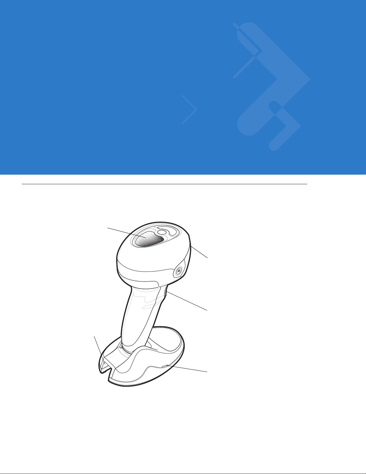
The Symbol DS9808 combines superior 1D and 2D omnidirectional bar code scanning and sub-second image
capture and transfer with a light-weight, hands-free/hand-held design. The digital scanner’s built-in stand
seamlessly accommodates both counter-top and hand-held use. Whether in hands-free (presentation) or
hand-held mode, the digital scanner ensures comfort and ease of use for extended periods of time.
Figure 1-1
Symbol DS9808 Digital Scanner
Page 20

1 - 2 Symbol DS9808 Product Reference Guide
Interfaces
The DS9808 digital scanner supports:
•
USB connection to a host. The digital scanner autodetects a USB host and defaults to the HID keyboard
interface type. Select other USB interface types by scanning programming bar code menus.This interface
supports the following international keyboards (for Windows® environment): North America, German,
French, French Canadian, Spanish, Italian, Swedish, UK English, Portuguese-Brazilian, and Japanese.
•
Standard RS-232 connection to a host. Scan bar code menus to set up communication of the digital scanner
with the host.
•
Connection to IBM 468X/469X hosts. Scan bar code menus to set up communication of the digital scanner
with the IBM terminal.
•
Keyboard Wedge connection to a host. The host interprets scanned data as keystrokes. Scan bar code
menus to set up communication of the digital scanner with the host. This interface supports the following
international keyboards (for Windows® environment): North America, German, French, French Canadian,
French Belgian, Spanish, Italian, Swedish, UK English, Portuguese-Brazilian, and Japanese.
Unpacking
Remove the digital scanner from its packing and inspect it for damage. If the scanner was damaged in transit,
contact Motorola Enterprise Mobility Support. See page xvi for contact information. KEEP THE PACKING. It is the
approved shipping container; use this to return the equipment for servicing.
Page 21
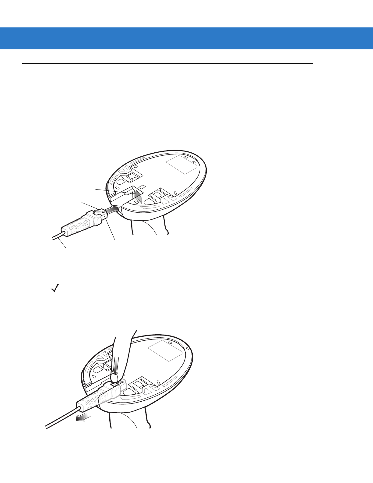
Setting Up the Digital Scanner
Clip
To h o st
Interface cable port
Interface cable modular
connector
Installing the Interface Cable
1. Plug the interface cable modular connector into the cable interface port on the bottom of the digital scanner’s
base (see Figure 1-2).
2. Gently tug the cable to ensure the connector is secure.
3. Connect the other end of the interface cable to the host (see the specific host chapter for information on host
connections).
Getting Started 1 - 3
Figure 1-2
Removing the Interface Cable
1. Press the cable’s modular connector clip through the access slot in the digital scanner’s base.
Figure 1-3
Installing the Cable
NOTE Different hosts require different cables. The connectors illustrated in each host chapter are examples only.
Connectors vary from those illustrated, but the steps to connect the digital scanner are the same.
Removing the Cable
2. Carefully slide out the cable.
Page 22
1 - 4 Symbol DS9808 Product Reference Guide
3. Follow the steps for Installing the Interface Cable to connect a new cable.
Connecting Power (if required)
If the host does not provide power to the digital scanner, connect an external power supply:
1. Connect the interface cable to the base of the digital scanner, as described in Installing the Interface Cable on
page 1-3.
2. Connect the other end of the interface cable to the host (refer to the host manual to locate the correct port).
3. Plug the power supply into the power jack on the interface cable. Plug the other end of the power supply into
an AC outlet.
Configuring the Digital Scanner
To configure the digital scanner use the bar codes included in this manual. See Chapter 4, User Preferences &
Miscellaneous Digital Scanner Options and Chapter 5, Imaging Preferences for information about programming the
digital scanner using bar code menus. Also see each host-specific chapter to set up connection to a specific host
type.
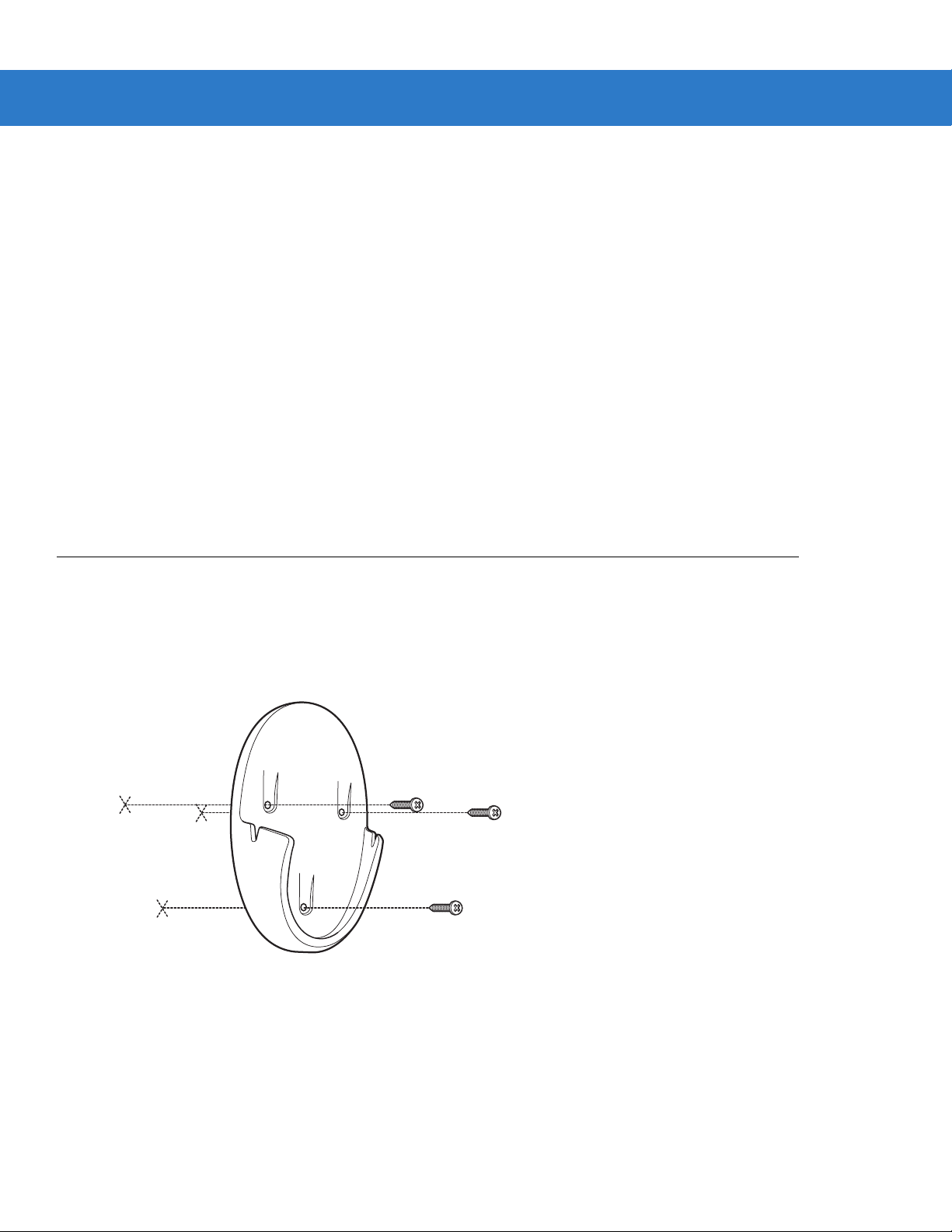
Mounting the Digital Scanner
An optional wall mount bracket is available for mounting the scanner to a wall or other vertical surface. To mount
the Symbol DS9808:
1. Place the bracket in its desired location on the wall, and insert three #6 screws through each screw hole in the
bracket.
Figure 1-4
2. Tighten the screws to secure the bracket to the wall.
Installing the Wall Mount Bracket
Page 23
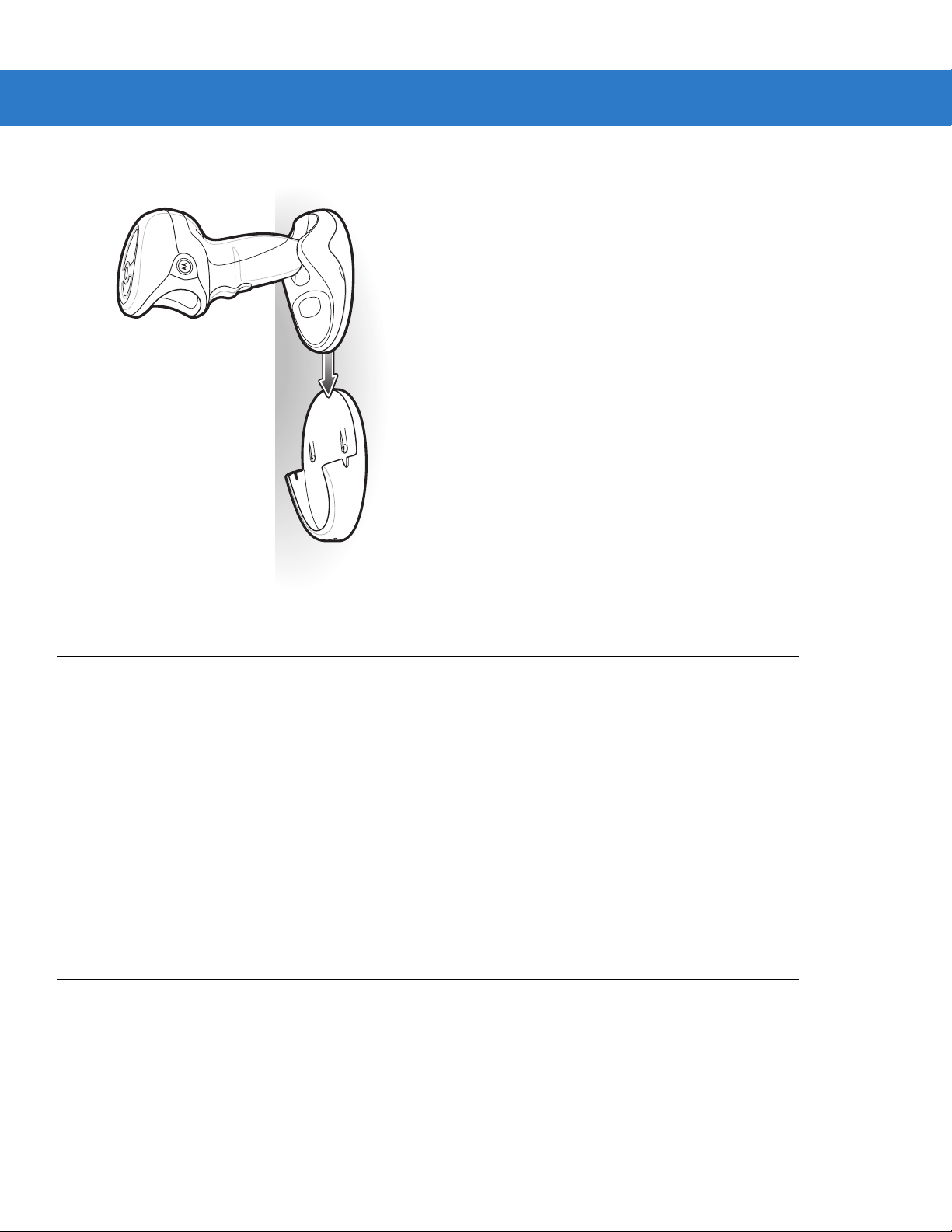
Getting Started 1 - 5
3. Slide the base of the digital scanner into the bracket, oriented so the scan window faces down.
Figure 1-5
Inserting the Symbol DS9808 into the Wall Mount Bracket
Accessories
Required Accessories
The digital scanner ships with an interface cable, a universal power supply, and the DS9808 Quick Start Guide. For
additional items, contact your local Motorola representative or business partner.
Optional Accessories
Contact Motorola to purchase the following accessories for the DS9808:
•
Wall Mount Bracket (see Mounting the Digital Scanner on page 1-4 for installation instructions or refer to
installation guide)
•
RFID module.
Electronic Article Surveillance (EAS) (Optional)
Because there are several Checkpoint EAS systems available, your local Checkpoint representative should install
the EAS cable. To contact your local Checkpoint representative inside the U.S. call 800-257-5540, ext. 4300.
Outside the U.S., call (609) 848-1800, ext. 4300.
If using an EAS cable, refer to the Electronic Article Surveillance Cable Installation Guide (p/n 70-32824-xx).
Page 24

1 - 6 Symbol DS9808 Product Reference Guide
Page 25
Chapter 2 Scanning
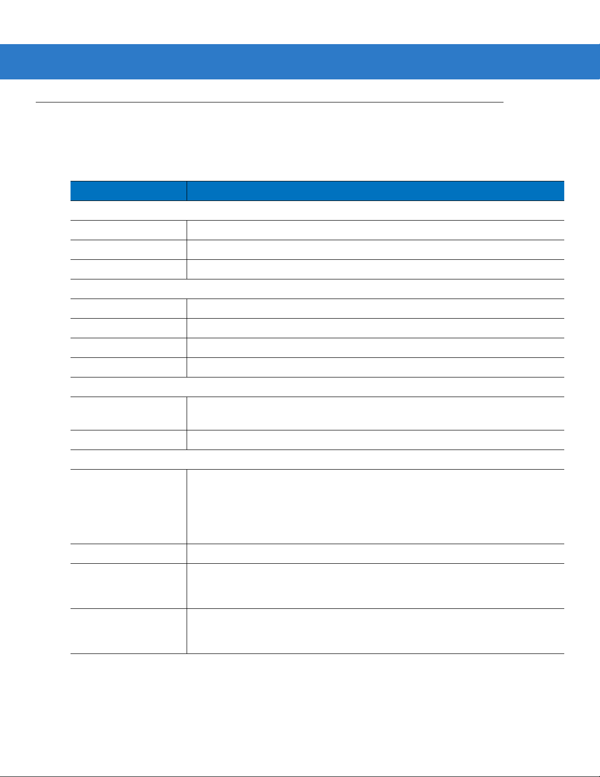
Scan Window
Multifunction Trigger
LED
Beeper
Interface cable port
Introduction
This chapter provides beeper and LED definitions, techniques involved in scanning bar codes, general instructions
and tips about scanning, and decode zone diagrams.
Figure 2-1
Parts
Page 26

2 - 2 Symbol DS9808 Product Reference Guide
Beeper Definitions
The digital scanner issues different beep sequences and patterns to indicate status. Table 2-1 defines beep
sequences that occur during both normal scanning and while programming the digital scanner.
Table 2-1
Standard Use
Low/medium/high beeps Power up.
Short high beep A bar code symbol was decoded (if decode beeper is enabled).
4 long low beeps Transmission error.
5 low beeps Conversion or format error.
Low/low/low/extra low beeps RS-232 receive error.
High beep The digital scanner detected a <BEL> character over RS-232.
RFID
Medium-high (two-tone) beep An RFID tag was read (if RFID read beeper is enabled).
High-medium/low/low beeps Unexpected RFID indication.
Image Capture
Low beep Snapshot mode started or completed.
High/low beeps Snapshot mode timed out.
Beeper Definitions
Beeper Sequence Indication
Parameter Menu Scanning
Low/high beeps Input error; incorrect bar code, programming sequence, or
High/low beeps Keyboard parameter selected. Enter value using numeric bar codes.
High/low/high/low beeps Successful program exit with change in parameter setting.
Code 39 Buffering
High/low beeps New Code 39 data was entered into the buffer.
3 long high beeps Code 39 buffer is full.
High/low/high beeps The Code 39 buffer was erased.
Low/high/low beeps The Code 39 buffer was erased or there was an attempt to clear or transmit an
empty buffer.
Low/high beeps A successful transmission of buffered data.
Macro PDF
2 low beeps
2 long low beeps
MPDF sequence buffered.
File ID error. A bar code not in the current MPDF sequence was scanned.
Cancel
scanned.
Page 27

Scanning 2 - 3
Table 2-1
3 long low beeps Out of memory. There is not enough buffer space to store the current MPDF
4 long low beeps Bad symbology. Scanned a 1D or 2D bar code in a MPDF sequence, a duplicate
5 long low beeps Flushing MPDF buffer.
Fast warble beep Aborting MPDF sequence.
Low/high beeps Flushing an already empty MPDF buffer.
Host Specific
USB only
4 short high beeps The digital scanner has not completed initialization. Wait several seconds and
Low/medium/high beeps
upon scanning a USB device
type
Beeper Definitions (Continued)
Beeper Sequence Indication
symbol.
MPDF label, a label in an incorrect order, or trying to transmit an empty or illegal
MPDF field.
scan again.
Communication with the host must be established before the digital scanner can
operate at the highest power level.
Low/medium/high beeps
occur more than once
RS-232 only
1 short high beep A <BEL> character is received and Beep on <BEL> is enabled.
The USB host can put the digital scanner in a state where power to the scanner is
cycled on and off more than once. This is normal and usually happens when the
PC cold boots.
Page 28
2 - 4 Symbol DS9808 Product Reference Guide
LED Definitions
In addition to beep sequences, the digital scanner uses a two-color LED to indicate status. Table 2-2 defines LED
colors that display during scanning.
Table 2-2
Hand-Held Scanning Standard Use
Green A bar code was successfully decoded or an RFID tag was read.
Red Transmission error, conversion or format error, or RS-232 receive error.
Off No power is applied to the digital scanner, or the scanner is on and ready to scan.
Hands-Free (Presentation) Scanning Standard Use
Green The scanner is on and ready to scan.
Momentarily Off A bar code was successfully decoded or an RFID tag was read.
Red Transmission error, conversion or format error, or RS-232 receive error.
Off No power is applied to the digital scanner, or the scanner is in low power mode.
Parameter Programming
Green Number expected. Enter value using numeric bar codes.
Red Input error: incorrect bar code, programming sequence, or Cancel scanned.
Standard LED Definitions
LED Indication
Successful program exit with change in parameter setting.
ADF Programming
Green Enter another digit. Add leading zeros to the front if necessary.
Enter another alphabetic character or scan the
All criteria or actions cleared for current rule, continue entering rule.
Delete last saved rule. The current rule is left intact.
All rules deleted.
Blinking Green Enter another criterion or action, or scan the
Green after Blinking Rule saved. Rule entry mode exited.
Cancel rule entry. Rule entry mode exited because of an error or the user asked to exit
rule entry.
Red Out of rule memory. Erase some existing rules, then try to save rule again.
Entry error, wrong bar code scanned, or criteria/action list is too long for a rule. Re-enter
criterion or action.
End of Message
Save Rule
bar code.
bar code.
Page 29
Scanning
Scanning 2 - 5
The Symbol DS9808 has a built-in, light-weight stand to easily accommodate both
hand-held scanning.
NOTE Certain areas of the digital scanner’s handle may feel warm at times. This is normal.
hands-free (presentation)
Hands-Free Scanning
The digital scanner is in
wall in the wall mount bracket. In this mode, the digital scanner operates in continuous (constant-on) mode, where
it automatically decodes a bar code presented in its field of view.
hands-free (presentation) mode
when it sits on a countertop, or when it is mounted on a
and
Figure 2-2
Scanning in Hands-Free Mode
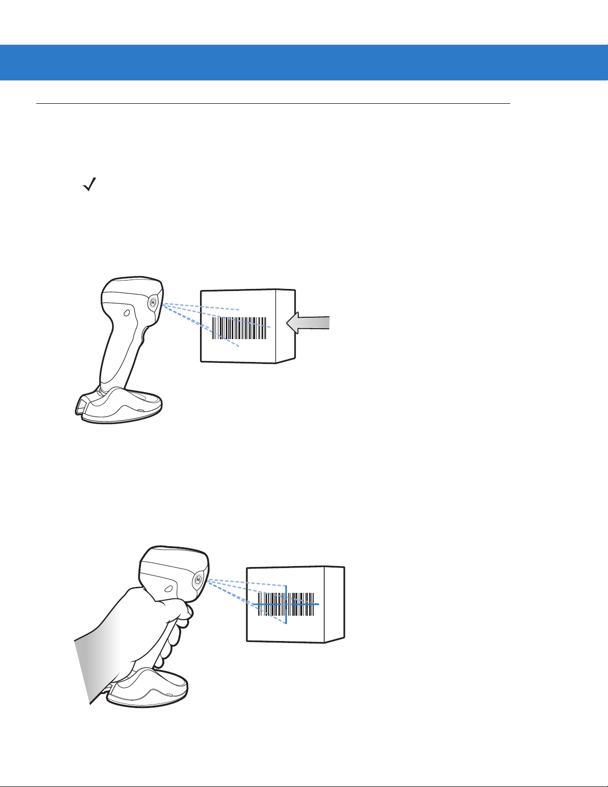
Hand-Held Scanning
DS9808-SR/DL Hand-Held Scanning
When lifted off the counter or removed from the wall mount bracket, the DS9808-SR/DL operates in standard
trigger mode. Aim the digital scanner at a bar code and pull the trigger to decode.
Figure 2-3
Scanning in Hand-Held Mode - DS9808-SR/DL
Page 30

2 - 6 Symbol DS9808 Product Reference Guide
DS9808-LR/LL Multifunction Trigger
The DS9808-LR/LL digital scanner includes a multifunction trigger which you can program to quickly switch
between imaging, laser scanning, and/or RFID reading. See Multifunction Mode Triggering (DS9808-LR/LL Only)
on page 4-19 for more information.
Figure 2-4
By default, this scanner automatically switches to a laser scanner when lifted off the counter for longer range 1D
bar code scanning. If the scanner detects a PDF bar code or cannot decode the bar code, it switches to imager
operation. After successful decode, time out, or trigger release, the digital scanner reverts to the laser engine for
the next trigger pull.
Scanning in Hand-Held Mode - DS9808-LR/LL
Aiming
Imager Aiming
When scanning, the digital scanner projects a red laser aiming pattern which allows positioning the bar code within
its field of view. See Decode Ranges on page 2-8 for the proper distance to achieve between the digital scanner
and a bar code.
Figure 2-5
If necessary, the digital scanner turns on its red LEDs to illuminate the target bar code.
Imager Aiming Pattern
Page 31

Scanning 2 - 7
Symbol
Aiming Pattern
1D bar code
2D bar code
0123 45
0123 45
0123 45
0123 45
RIGHT
012345
WRONG
012345
To scan a bar code, center the symbol in any orientation within the aiming pattern. Be sure the entire symbol is
within the rectangular area formed by the cross pattern.
Figure 2-6
Scanning Orientation with Imager Aiming Pattern
The digital scanner can also read a bar code presented within the aiming pattern but not centered. The top
examples in Figure 2-7 show acceptable aiming options, while the bottom examples can not be decoded.
Figure 2-7
Acceptable and Incorrect Aiming
Laser Aiming
In hand-held mode, The DS9808-LR/LL digital scanner projects a laser line by default. Ensure the scan line
crosses every bar and space of the symbol.
Figure 2-8
The aiming pattern (or laser line) is smaller when the digital scanner is closer to the symbol and larger when it is
farther from the symbol. Scan symbols with smaller bars or elements (mil size) closer to the digital scanner, and
those with larger bars or elements (mil size) farther from the digital scanner.
The digital scanner beeps to indicate that it successfully decoded the bar code. For more information on beeper
and LED definitions, see Table 2-1 and Table 2-2.
Scanning Orientation with Laser Aiming Pattern
Page 32

2 - 8 Symbol DS9808 Product Reference Guide
Decode Ranges
Table 2-3
Symbol Density Bar Code Type
Table 2-4
Symbol Density Bar Code Type
DS9808-LR/LL 1D Laser Decode Distances
5.0 mil Code 39 0 in / 0 cm 5.0 in / 12.7 cm
10 mil 80% UPCEAN 0 in / 0 cm 13.5 in / 34.3 cm
13 mil 100% UPC 0 in / 0 cm 18.0 in / 45.7 cm
DS9808-SR/DL 1D Imager Decode Ranges
5.0 mil Code 39 0 in / 0 cm 4.5 in / 11.4 cm
10 mil 80% UPCEAN 0 in / 0 cm 8.5 in / 21.6 cm
13 mil 100% UPC 0 in / 0 cm 10.5 in / 26.7 cm
Typical Working Ranges
Near Far
Typical Working Ranges
Near Far
Table 2-5
Symbol Density Bar Code Type
Table 2-6
Symbol Density Bar Code Type
2D Imager Decode Ranges (All Models)
6.6 mil PDF417 0 in / 0 cm 5.0 in / 12.7 cm
10 mil Data Matrix 0 in / 0 cm 6.0 in / 15.2 cm
Hands-Free Decode Ranges (All Models)
5.0 mil Code 39 0 in / 0 cm 4.5 in / 11.4 cm
10 mil 80% UPCEAN 0 in / 0 cm 7.0 in / 17.8 cm
13 mil 100% UPC 0 in / 0 cm 8.0 in / 20.3 cm
6.6 mil PDF417 0 in / 0 cm 4.5 in / 11.4 cm
10 mil Data Matrix 0 in / 0 cm 4.5 in / 11.4 cm
Typical Working Ranges
Near Far
Typical Working Ranges
Near Far
Page 33

Chapter 3 Maintenance & Technical
Specifications
Introduction
This chapter provides suggested digital scanner maintenance, troubleshooting, technical specifications, and signal
descriptions (pinouts).
Maintenance
Cleaning the scan window is the only maintenance required. A dirty window can affect scanning accuracy.
•
Do not allow abrasive material to touch the window.
•
Remove any dirt particles with a damp cloth.
•
Wipe the window using a tissue moistened with ammonia/water.
•
Do not spray water or other cleaning liquids directly into the window.
Page 34

3 - 2 Symbol DS9808 Product Reference Guide
Troubleshooting
Table 3-1
The aiming pattern does not
appear when pressing the
trigger.
Digital scanner emits short
low/short medium/short high
beep sequence (power-up beep
sequence) more than once.
Troubleshooting
Problem Possible Causes Possible Solutions
No power to the digital scanner. If the configuration requires a power
supply, re-connect the power supply.
Incorrect host interface cable is used. Connect the correct host interface
cable.
Interface/power cables are loose. Re-connect cables.
Digital scanner is disabled. For IBM 468x and USB IBM hand-held,
IBM table top, and OPOS modes,
enable the digital scanner via the host
interface. Otherwise, see the technical
person in charge of scanning.
If using RS-232 Nixdorf B mode, CTS
is not asserted.
Aiming pattern is disabled. Enable the aiming pattern. See
The USB bus may put the digital
scanner in a state where power to the
scanner is cycled on and off more than
once.
Assert CTS line.
Hand-Held Decode Aiming Pattern on
page 4-30
Normal during host reset.
.
Digital scanner emits aiming
pattern, but does not decode the
bar code.
Digital scanner emits 4 short
high beeps during decode
attempt.
Digital scanner is not programmed for
the correct bar code type.
Bar code symbol is unreadable. Scan test symbols of the same bar
The symbol is not completely inside
aiming pattern.
Digital scanner has not completed
USB initialization.
Program the digital scanner to read that
type of bar code. See
Symbologies
code type to determine if the bar code
is defaced.
Move the symbol completely within the
aiming pattern.
Wait several seconds and scan again.
.
Chapter 10,
Page 35

Maintenance & Technical Specifications 3 - 3
Table 3-1
Digital scanner decodes bar
code, but does not transmit the
data to the host.
Host displays scanned data
incorrectly.
Troubleshooting (Continued)
Problem Possible Causes Possible Solutions
Digital scanner is not programmed for
the correct host type.
Interface cable is loose. Re-connect the cable.
If the digital scanner emits 4 long low
beeps, a transmission error occurred.
If the digital scanner emits 5 low
beeps, a conversion or format error
occurred.
If the digital scanner emits
low/high/low beeps, it detected an
invalid ADF rule.
If the digital scanner emits high/low
beeps, the scanner is buffering Code
39 data.
Digital scanner is not programmed to
work with the host.
Scan the appropriate host type
programming bar code. See the
chapter corresponding to the host type.
Set the scanner's communication
parameters to match the host's setting.
Configure the digital scanner's
conversion parameters properly.
Program the correct ADF rules. Refer
to the Advanced Data Formatting
Programmer Guide.
Normal scanning a Code 39 bar code
and the Code 39 Buffering option is
enabled.
Scan the appropriate host type
programming bar code.
Digital scanner emits
high/high/high/low beeps when
not in use.
Digital scanner emits low/high
beeps during programming.
Digital scanner emits
low/high/low/high beeps during
programming.
For RS-232, set the digital scanner's
communication parameters to match
the host's settings.
For a Keyboard Wedge configuration,
program the system for the correct
keyboard type, and turn off the CAPS
LOCK key.
Program the proper editing options
(e.g., UPC-E to UPC-A Conversion).
RS-232 receive error. Normal during host reset. Otherwise,
set the digital scanner's RS-232 parity
to match the host setting.
Input error or
scanned.
Out of ADF parameter storage space. Erase all rules and re-program with
Cancel
bar code was
Scan the correct numeric bar codes
within range for the parameter
programmed.
shorter rules.
Page 36

3 - 4 Symbol DS9808 Product Reference Guide
Table 3-1
Troubleshooting (Continued)
Problem Possible Causes Possible Solutions
Digital scanner emits
low/high/low beeps.
Digital scanner emits a
power-up beep after changing
USB host type.
Digital scanner emits one high
beep when not in use.
NOTE If after performing these checks the digital scanner still experiences problems, contact the distributor or
call Motorola Enterprise Mobility Support. See page xvi for the telephone numbers.
Clearing Code 39 buffer. Normal when scanning the Code 39
Buffering
Clear Buffer
bar code or
upon attempt to transmit an empty
Code 39 buffer.
The USB bus re-established power to
Normal when changing USB host type.
the digital scanner.
In RS-232 mode, a <BEL> character
was received and Beep on <BEL>
option is enabled.
Normal when
Beep on <BEL>
is
enabled and the digital scanner is in
RS-232 mode.
Page 37

Technical Specifications
Maintenance & Technical Specifications 3 - 5
Table 3-2
Physical Characteristics
Dimensions 8 in. (max) H x 5.4 in. L x 3.4 in. W
Weight 12 oz. (340 g)
Power
Performance Characteristics: DS9808-SR/DL and DS9808-LR/LL Imager Engine
Light Source Aiming pattern: 650 nm laser diode
Imager Field of View
(Vertical x Horizontal)
Roll
Pitch
Yaw
Swipe Speed Programmable up to 100 in. (254 cm) per second
Technical Specifications
Item Description
With optional RFID module
20.3 cm (max) H x 13.7 cm L x 8.6 cm W
5 +/-10%VDC @ 450 mA nominal
5 +/-10%VDC @ 1.2 A nominal (special power supply and cable required)
Illumination: 630 nm LED
39º (H) x 25º (V)
360º
+/- 65º
+/- 60º
Performance Characteristics: DS9808-LR/LL Laser Engine
Light Source 650nm laser diode
Scan Angle 40º nominal
Symbology Decode Capability
1D UPC/EAN, UPC/EAN with supplementals, Bookland EAN, ISSN, UCC Coupon
Extended Code, Code 128, GS1-128, ISBT 128, Code 39, Code 39 Full ASCII,
Trioptic Code 39, Code 32, Code 93, Code 11, Matrix 2 of 5, Interleaved 2 of 5,
Discrete 2 of 5, Codabar, MSI, Chinese 2 of 5, GS1 DataBar variants
2D PDF417, MicroPDF417, Composite Codes, TLC-39, Data Matrix, Maxicode,
QR Code, MicroQR, Aztec
Postal US Postnet and Planet, UK Postal, Japan, Australian, Netherlands KIX Code,
USPS 4CB/One Code/Intelligent Mail, UPU FICS Postal
Typical Working Distance See
Motion Tolerances Swipe speed: 100 inches per second at full illumination, measured on
Decode Ranges on page 2-8
100% UPC bar code 80% MRD at 4 inches distance form the housing
.
Page 38

3 - 6 Symbol DS9808 Product Reference Guide
Table 3-2
Interfaces Supported The scanner supports the following protocols over USB: HID Keyboard (default
User Environment
Operating Temperature 32º F to 104º F (0º C to 40º C)
Storage Temperature -40º F to 158º F (-40º C to 70º C)
Humidity 5% to 95%, non-condensing
Drop Specifications Withstands multiple 5 ft. (1.52 m) drops to concrete at operating temperature
Ambient Light Immunity Immune to normal artificial indoor and natural outdoor (direct sunlight) lighting.
Regulatory
Electrical Safety UL6950-1, CSA C22.2 No. 60950-1, EN60950-1 / IEC60950-1
Laser Safety EN60825-1:1994 +A1: 2002 +A2 :2001, IEC60825-1, 21CFR1040.10 and
Technical Specifications (Continued)
Item Description
mode), SNAPI, COM Port Emulation, IBM SurePOS (Yellowstone) (IBM Handheld,
IBM Tabletop, OPOS)
The scanner supports the following protocols over RS232: Standard, Wincor
Nixdorf, ICL, Fujitsu, Olivetti
extremes.
21CFR1040.11, CDRH Class II, IEC Class 2
EMI/RFI FCC Part 15 Class B, ICES-003 Class B, EN 55022, EN 55024
AS/NZS 4268:2008, Japan VCCI
RoHS Compliance with RoHS Directive 2002/95/EEC
Mounting Options
(Accessories)
Power Supplies Power supplies are available for applications that do not supply power over the
Wall mount bracket
host cable.
Page 39

Digital Scanner Signal Descriptions
Pin 10
Pin 1
Interface cable
modular connector
Maintenance & Technical Specifications 3 - 7
Figure 3-1
The signal descriptions in Table 3-3 apply to the connectors on the Symbol DS9808 digital scanner and are for
reference only.
Table 3-3
Pin IBM RS-232
1
2
3
4
5
6
7
8
9
10
Digital Scanner Cable Pinouts
Symbol DS9808 Digital Scanner Signal Pin-outs
Keyboard
Wedge
Reserved Reserved Reserved Jump to Pin 6
Power Power Power Power
Ground Ground Ground Ground
IBM_A(+) TxD KeyClock Reserved
Reserved RxD TermData D +
IBM_B(-) RTS KeyData Jump to Pin 1
Reserved CTS TermClock D -
Reserved Reserved Reserved Reserved
Reserved Reserved Reserved Reserved
Reserved Reserved Reserved Reserved
USB
Page 40

3 - 8 Symbol DS9808 Product Reference Guide
Page 41

Chapter 4 User Preferences & Miscellaneous
*High Volume
(00h)
Feature/Option
* Indicates Default
Option Hex Value
Digital Scanner Options
Introduction
You can program the digital scanner to perform various functions, or activate different features. This chapter
describes each user preference feature and provides programming bar codes for selecting these features.
The digital scanner ships with the settings shown in Table 4-1 on page 4-2 (also see Appendix A, Standard Default
Parameters for all host device and miscellaneous defaults). If the default values suit requirements, programming is
not necessary.
To set feature values, scan a single bar code or a short bar code sequence. The settings are stored in non-volatile
memory and are preserved even when the digital scanner is powered down.
NOTE Most computer monitors allow scanning the bar codes directly on the screen (when using the imaging
engine). When scanning from the screen, be sure to set the document magnification to a level where you
can see the bar code clearly, and bars and/or spaces are not merging.
If not using a USB cable, select a host type (see each host chapter for specific host information) after the power-up
beeps sound. This is only necessary upon the first power-up when connected to a new host.
To return all features to default values, scan the Set Default Parameter on page 4-4. Throughout the programming
bar code menus, asterisks indicate (
*)default values.
Page 42

4 - 2 Symbol DS9808 Product Reference Guide
Scanning Sequence Examples
In most cases, scanning one bar code sets the parameter value. For example, to set the beeper tone to high, scan
the High Frequency (beeper tone) bar code listed under Beeper Tone on page 4-6. The digital scanner issues a
fast warble beep and the LED turns green, signifying a successful parameter entry.
Other parameters, such as Serial Response Time-Out or Data Transmission Formats, require scanning several
bar codes. See these parameter descriptions for this procedure.
Errors While Scanning
Unless otherwise specified, to correct an error during a scanning sequence, just re-scan the correct parameter.
User Preferences/Miscellaneous Options Parameter Defaults
Table 4-1 lists defaults for user preferences parameters. To change the default values, scan the appropriate bar
codes in this guide. These new values replace the standard default values in memory. To recall the default
parameter values, scan the Set Default Parameter on page 4-4.
NOTE See Appendix A, Standard Default Parameters for all user preferences, hosts, symbologies, and
miscellaneous default parameters.
Table 4-1
User Preferences
Set Default Parameter Set Defaults 4-4
Parameter Bar Code Scanning ECh Enable 4-5
Beep After Good Decode 38h Enable 4-5
Beeper Tone 91h Medium 4-6
Beeper Volume 8Ch High 4-7
Beeper Duration F1 74h Medium 4-8
Hands-Free Mode F1h 76h Enable 4-9
Presentation Performance Mode F1 8Ah Standard 4-9
Time Delay to Presentation Idle Mode F1 97h 1 Minute 4-11
User Preferences Parameter Defaults
Parameter
Parameter
Number
Default
Page
Number
Time Delay to Presentation Sleep Mode F1 96h 1 Hour 4-13
Low Power Mode 80h Disable 4-15
Time Delay to Low Power Mode 92h 1 Hour 4-16
Hand-Held Trigger Mode 8Ah Auto Aim 4-18
Page 43

User Preferences & Miscellaneous Digital Scanner Options 4 - 3
Table 4-1
Multifunction Triggering (DS9808-LR/LL Only) Single Trigger 4-19
Host Trigger Mode (DS9808-LR/LL Only) F1 7Ch Imager Decoding 4-24
Picklist Mode F0h 92h Disabled Always 4-26
Continuous Bar Code Read F1 89h Disable 4-27
Decode Session Timeout 88h 9.9 Sec 4-27
Timeout Between Decodes, Same Symbol 89h 0.5 Sec 4-28
Timeout Between Decodes, Different Symbols 90h 0.2 Sec 4-28
User Preferences Parameter Defaults (Continued)
Parameter
Trigger A F1 77h Laser Preferred Decoding 4-20
Trigger B F1 78h Trigger A value 4-21
Trigger A + B F1 79h Ignore 4-22
Laser Preferred Timeout F1 7Dh 1.5 seconds 4-23
Dual Trigger Debounce Timeout F1 7Ah 0.05 seconds 4-23
Dual Trigger Processing F1 7Bh Wait 4-24
Parameter
Number
Default
Page
Number
Fuzzy 1D Processing F1h 02h Enable 4-29
Hand-Held Decode Aiming Pattern F0h 32h Enable 4-30
Hands-Free Decode Aiming Pattern F1h 4Eh Enable
Presentation Mode Field of View F1h 61h Full 4-32
Decoding Illumination F0h, 2Ah Enable 4-33
Miscellaneous Options
Transmit Code ID Character 2Dh None 4-34
Prefix Value 63h, 69h 7013 <CR><LF> 4-35
Suffix 1 Value
Suffix 2 Value
Scan Data Transmission Format EBh Data as is 4-36
FN1 Substitution Values 67h 6Dh Set 4-37
Transmit “No Read” Message 5Eh Disable 4-38
62h 68h
64h 6Ah
7013 <CR><LF> 4-35
for PDF 4-31
Page 44

4 - 4 Symbol DS9808 Product Reference Guide
User Preferences
Set Default Parameter
You can reset the digital scanner to two types of defaults: factory defaults or custom defaults. Scan the appropriate
bar code below to reset the decoder to its default settings and/or set its current settings as custom defaults.
•
Set Defaults - Scan this bar code to reset all default parameters as follows.
• If you previously set custom defaults by scanning Write to Custom Defaults, scan Set Defaults to
retrieve and restore the decoder’s custom default settings.
• If you did not set custom defaults, scan Restore Defaults to restore the factory default values listed in
Table A-1.
•
Set Factory Defaults - Scan this bar code to restore the factory default values listed in Table A-1. This
deletes any custom defaults set.
•
Write to Custom Defaults - Scan this bar code to set the current decoder settings as custom defaults. Once
set, you can recover custom default settings by scanning Restore Defaults.
*Set Defaults
Write to Custom Defaults
Set Factory Defaults
Page 45

User Preferences & Miscellaneous Digital Scanner Options 4 - 5
Parameter Bar Code Scanning
Parameter # ECh
To disable the decoding of parameter bar codes, including the Set Defaults parameter bar codes, scan the
Disable Parameter Scanning bar code below. To enable decoding of parameter bar codes, scan Enable
Parameter Scanning.
*Enable Parameter Bar Code Scanning
(01h)
Disable Parameter Bar Code Scanning
(00h)
Beep After Good Decode
Parameter # 38h
Scan a bar code below to select whether or not the digital scanner beeps after a good decode. If selecting Do Not
Beep After Good Decode, the beeper still operates during parameter menu scanning and to indicate error
conditions.
*Beep After Good Decode
(Enable)
(01h)
Do Not Beep After Good Decode
(Disable)
(00h)
Page 46

4 - 6 Symbol DS9808 Product Reference Guide
Beeper Tone
Parameter # 91h
To select a decode beep frequency (tone), scan one of the following bar codes.
Off
(03h)
Low Tone
(02h)
*Medium Tone
(01h)
Medium to High Tone (2-tone)
(04h)
High Tone
(00h)
Page 47

User Preferences & Miscellaneous Digital Scanner Options 4 - 7
Beeper Volume
Parameter # 8Ch
To select a beeper volume, scan the Low Volume, Medium Volume, or High Volume bar code.
Low Volume
(02h)
Medium Volume
(01h)
*High Volume
(00h)
Page 48

4 - 8 Symbol DS9808 Product Reference Guide
Beeper Duration
Parameter # F1 74h
To select the duration for the beeper, scan one of the following bar codes.
Short
(00h)
* Medium
(01h)
Long
(02h)
Page 49

User Preferences & Miscellaneous Digital Scanner Options 4 - 9
Hands-Free Mode
Parameter # F1h 76h
In
hands-free
with a bar code. Lifting the digital scanner causes it to behave according to the setting of the Hand-Held Trigger
Mode on page 4-18.
If you select Disable Hands-Free Mode, the digital scanner behaves according to the setting of the Hand-Held
Trigger Mode regardless of whether it is hand-held or on a countertop.
mode, when you place the digital scanner on the countertop, it automatically triggers when presented
*Enable Hands-Free Mode
(01h)
Disable Hands-Free Mode
(00h)
Presentation Performance Mode
Parameter # F1 8Ah
Standard Presentation Mode is optimized for general purpose scanning. Select Enhanced Presentation Mode
to accommodate a faster bar code swiping speed and/or a reduced decode range (e.g., to better match EAS
deactivation range or eliminate inadvertent reads).
*Standard Presentation Mode
(02h)
Enhanced Presentation Mode
(00h)
Page 50

4 - 10 Symbol DS9808 Product Reference Guide
Active Mode Idle Mode Sleep Mode Low Power Mode
Time Delay to
Presentation
Idle Mode value
Time Delay to
Presentation
Sleep Mode value
Time Delay to
Low Power
Mode value
Note: Time delays are cumulative.
Digital Scanner Activity Modes
The digital scanner is capable of four modes of activity:
•
Active Mode - The digital scanner uses full illumination for active scanning.
•
Idle Mode - In presentation mode only, the digital scanner’s illumination dims after a programmable time
period. See Time Delay to Presentation Idle Mode on page 4-11. The digital scanner wakes when it is lifted or
senses motion, upon presentation of a bar code, or upon a trigger pull.
•
Sleep Mode - In presentation mode only, the digital scanner’s illumination shuts off after a programmable
time period after Idle Mode has expired. See Time Delay to Presentation Sleep Mode on page 4-13. The
digital scanner wakes when it is lifted or senses motion, upon presentation of a bar code (depending on
ambient light conditions), or upon a trigger pull.
•
Low Power Mode - The digital scanner enters a low power consumption mode after Sleep Mode has
expired, in which the LEDs turn off in order to conserve energy and prolong the life of the scanner. See Low
Power Mode. In hand-held mode, this occurs immediately after the programmed Time Delay to Low Power
Mode. In presentation mode, this occurs after idle mode and sleep mode. The digital scanner wakes when it
is lifted, senses a trigger pull, or when the host attempts to communicate.
NOTE The digital scanner does not use Low Power Mode when connected to a USB or IBM host.
Figure 4-1
Power Levels
Page 51

User Preferences & Miscellaneous Digital Scanner Options 4 - 11
Time Delay to Presentation Idle Mode
Parameter # F1 97h
In Presentation Mode, this parameter sets the time the digital scanner remains active before entering idle mode
with dim illumination. The digital scanner wakes upon presentation of a bar code or a trigger pull.
Disable
(00h)
1 Second
(01h)
10 Seconds
(0Ah)
5 Minutes
(15h)
*1 Minute
(11h)
15 Minutes
(1Bh)
Page 52

4 - 12 Symbol DS9808 Product Reference Guide
Time Delay to Presentation Idle Mode (continued)
30 Minutes
(1Dh)
45 Minutes
(1Eh)
1 Hour
(21h)
6 Hours
(26h)
3 Hours
(23h)
9 Hours
(29h)
Page 53

User Preferences & Miscellaneous Digital Scanner Options 4 - 13
Time Delay to Presentation Sleep Mode
Parameter # F1 96h
In Presentation Mode, this parameter sets the time the digital scanner remains active before entering sleep mode
with no illumination. The digital scanner wakes when it senses motion, upon presentation of a bar code, or a trigger
pull.
NOTE Digital scanner performance is not guaranteed in dim conditions.
Disable
(00h)
10 Seconds
(0Ah)
5 Minutes
(15h)
1 Second
(01h)
1 Minute
(11h)
Page 54

4 - 14 Symbol DS9808 Product Reference Guide
Time Delay to Presentation Sleep Mode (continued)
15 Minutes
(1Bh)
30 Minutes
(1Dh)
45 Minutes
(1Eh)
3 Hours
(23h)
*1 Hour
(21h)
6 Hours
(26h)
9 Hours
(29h)
Page 55

User Preferences & Miscellaneous Digital Scanner Options 4 - 15
Low Power Mode
Parameter # 80h
If enabled, the digital scanner enters a low power consumption mode after Sleep Mode has expired, in which the
LEDs turn off in order to conserve energy and prolong the life of the scanner. In hand-held mode, this occurs
immediately after the programmed Time Delay to Low Power Mode. In presentation mode, this occurs after idle
mode and sleep mode. The digital scanner wakes when it is lifted, senses a trigger pull, or when the host attempts
to communicate.
If disabled, power remains on after each decode attempt.
*Disable Low Power Mode
(00h)
Enable Low Power Mode
(01h)
Page 56

4 - 16 Symbol DS9808 Product Reference Guide
Time Delay to Low Power Mode
Parameter # 92h
NOTE This parameter only applies when Low Power Mode is enabled.
This parameter sets the time the digital scanner remains active before entering lower power mode (after the
applicable activity mode - see Digital Scanner Activity Modes on page 4-10). The digital scanner wakes upon
trigger pull or when the host attempts to communicate with the digital scanner.
1 Second
(11h)
1 Minute
(21h)
15 Minutes
(2Bh)
10 Seconds
(1Ah)
5 Minutes
(25h)
Page 57

User Preferences & Miscellaneous Digital Scanner Options 4 - 17
Time Delay to Low Power Mode (continued)
30 Minutes
(2Dh)
45 Minutes
(2Eh)
*1 Hour
(31h)
6 Hours
(36h)
3 Hours
(33h)
9 Hours
(39h)
Page 58

4 - 18 Symbol DS9808 Product Reference Guide
Hand-Held Trigger Mode
Parameter # 8Ah
Select one of the following trigger modes for the digital scanner:
•
Standard (Level) - A trigger pull activates decode processing. Decode processing continues until the bar
code decodes, you release the trigger, or the Decode Session Timeout occurs.
•
Presentation (Blink) - The digital scanner activates decode processing when it detects a bar code in its field
of view. After a period of non-use, the digital scanner enters a low power mode, in which the LEDs turn off
until the digital scanner senses motion.
NOTE Laser scanning is not applicable in hand-held presentation mode.
•
Auto Aim - If the primary trigger (trigger A) is set to imager, this trigger mode turns on the laser aiming
pattern when you lift the digital scanner. A trigger pull activates decode processing. After 2 seconds of
inactivity the aiming pattern shuts off.
Standard (Level)
(00h)
*Auto Aim
(09h)
Presentation (Blink)
(07h)
Page 59

User Preferences & Miscellaneous Digital Scanner Options 4 - 19
Trigger A
Trigger B
Multifunction Mode Triggering (DS9808-LR/LL Only)
NOTE Multifunction Mode Triggering is only available in the dual-engine (imager and laser) models of the digital
scanner.
You can set trigger options for each of the digital scanner’s trigger positions. For example, set Trigger A (pressed
with your index finger) to imager decoding, set Trigger B (pressed with your middle finger) for laser decoding, and
set Trigger A + B (pressed with both fingers) to RFID reading.
The default operation is single trigger, so if you do not assign values to each trigger option (or assign Trigger A
only), Trigger B operates the same as Trigger A, and a dual trigger pull is ignored.
Select one of the following functions for each trigger using the bar codes on the next few pages:
•
Laser Preferred Decoding - Programs the trigger for decoding using the laser engine first, then the imager
if a decode does not occur. See Scanning on page 2-5 for more information.
•
Imager Decoding - Programs the trigger for decoding using the imager engine.
•
RFID Reading - Programs the trigger for reading RFID tags.
•
Imager Plus RFID - A trigger pull attempts decode using the imager engine, and turns on the optional RFID
reader, if available, to read RFID tags.
•
Laser Preferred Plus RFID - A trigger pull attempts decode using the laser engine first, then the imager if a
decode does not occur, and also turns on the optional RFID reader, if available, to read RFID tags.
•
Laser Only Decoding - Programs the trigger for decoding using the laser engine only.
•
Set to Trigger A Value (Trigger B Only) - Sets Trigger B to the same value as Trigger A. This allows you to
automatically program Trigger B upon selecting the function of Trigger A.
•
Ignore Dual Trigger Pull (Trigger A+B Only) - Uses the mode of the first trigger pull only. This increases
triggering efficiency when the dual trigger is not needed.
Figure 4-2
Trigger Locations
Page 60

4 - 20 Symbol DS9808 Product Reference Guide
Trigger A (DS9808-LR/LL Only)
Parameter # F1 77h
*Laser Preferred Decoding
(00h)
Imager Decoding
(01h)
RFID Reading
(02h)
Laser Preferred Plus RFID
(04h)
Imager Plus RFID
(03h)
Laser Only Decoding
(06h)
Page 61

Trigger B (DS9808-LR/LL Only)
Parameter # F1 78h
Laser Preferred Decoding
(00h)
User Preferences & Miscellaneous Digital Scanner Options 4 - 21
Imager Decoding
(01h)
RFID Reading
(02h)
Preferred Plus RFID
Laser
(04h)
Imager Plus RFID
(03h)
*Set to Trigger A Value
(05h)
Laser Only Decoding
(06h)
Page 62

4 - 22 Symbol DS9808 Product Reference Guide
Trigger A+B (DS9808-LR/LL Only)
Parameter # F1 79h
Laser Preferred Decoding
(00h)
Imager Decoding
(01h)
RFID Reading
(02h)
Preferred Plus RFID
Laser
(04h)
Imager Plus RFID
(03h)
*Ignore Dual Trigger Pull (Use Mode of First Trigger Pull)
(05h)
Laser Only Decoding
(06h)
Page 63

User Preferences & Miscellaneous Digital Scanner Options 4 - 23
Laser Preferred Timeout (DS9808-LR/LL Only)
Parameter # F1 7Dh
If Multifunction Mode Triggering is set to Laser Preferred Decoding, use this parameter to set the time period that
the laser remains on before using the imager if a decode does not occur.
To set the timeout, scan the bar code below, followed by two bar codes from Appendix D, Numeric Bar Codes that
correspond to the desired time in the range of 0.1 to 9.9 seconds. To correct an error or change the selection, scan
Cancel on page D-2. The default is 1.5 seconds.
Laser Preferred Timeout
Dual Trigger Debounce Timeout (DS9808-LR/LL Only)
Parameter # F1 7Ah
Set a time period in which both triggers must be pulled in order for the digital scanner to recognize this as a dual
trigger pull. In other words, if you pull Trigger A, then Trigger B after this timeout expires, the digital scanner
behaves as if you pulled Trigger A only.
To set the timeout, scan the bar code below, followed by two bar codes from Appendix D, Numeric Bar Codes that
correspond to the desired time in the range of 0.00 to 0.99 seconds. Enter a trailing zero for single digit numbers.
For example, to set a Debounce Timeout of 0.50 seconds, scan the bar code below, then scan the 5 and 0 bar
codes. To correct an error or change the selection, scan Cancel on page D-2.
The default is 0.05 seconds.
Dual Trigger Debounce Timeout
Page 64

4 - 24 Symbol DS9808 Product Reference Guide
Dual Trigger Processing (DS9808-LR/LL Only)
Parameter # F1 7Bh
Select whether the digital scanner processes the first trigger pull immediately, or waits until the Dual Trigger
Debounce Timeout expires before processing. If the second trigger pull occurs within the timeout, the scanner
switches to the combination function.
Process Immediately
*Wait for Timeout Before Processing
Host Triggering (DS9808-LR/LL Only)
Parameter # F1 7Ch
Set an option for host-initiated triggering:
•
Laser Preferred Decoding - Programs the host trigger for decoding using the laser engine first, then the
imager if a decode does not occur. See Scanning on page 2-5 for more information.
•
Imager Decoding - Programs the trigger for decoding using the imager engine.
•
RFID Reading - Programs the trigger for reading RFID tags.
•
Imager Plus RFID - A trigger pull attempts decode using the imager engine, and turns on the optional RFID
reader, if available, to read RFID tags.
•
Laser Preferred Plus RFID - A trigger pull attempts decode using the laser engine first, then the imager if a
decode does not occur, and also turns on the optional RFID reader, if available, to read RFID tags.
•
Laser Only Decoding - Programs the trigger for decoding using the laser engine only.
Page 65

Host Triggering (continued)
Laser Preferred Decoding
(00h)
User Preferences & Miscellaneous Digital Scanner Options 4 - 25
*Imager Decoding
(01h)
RFID Reading
(02h)
Preferred Plus RFID
Laser
(04h)
Imager Plus RFID
(03h)
Laser Only Decoding
(06h)
Page 66

4 - 26 Symbol DS9808 Product Reference Guide
Picklist Mode
Parameter # F0h 92h
Picklist mode enables the digital scanner to decode only bar codes that are aligned under the laser crosshair.
Select one of the following picklist modes for the digital scanner:
•
Disabled Always - Picklist mode is always disabled.
•
Enabled in Hand-Held Mode - Picklist mode is enabled when the digital scanner is out of hands-free mode
and disabled when the digital scanner is in presentation mode.
•
Enabled in Hands-Free Mode - Picklist mode is enabled when the digital scanner is in hands-free mode
only.
•
Enabled Always - Picklist mode is always enabled.
NOTE For the DS9808-LR/LL, if you configure Trigger B for Imager Decoding and enable Picklist Mode,
activating Trigger B turns on the imager aiming pattern, and releasing the trigger activates decoding.
*Disabled Always
(00h)
Enabled in Hands-Free Mode
(03h)
Enabled in Hand-Held Mode
(01h)
Enabled Always
(02h)
Page 67

User Preferences & Miscellaneous Digital Scanner Options 4 - 27
Continuous Bar Code Read
Parameter # F1 89h
Enable this to report every bar code while the trigger is pressed.
NOTE Motorola strongly recommends enabling Picklist Mode on page 4-26 with this feature. Disabling Picklist
Mode can cause accidental decodes when more than one bar code is in the imaging engine's field of view.
*Disable Continuous Bar Code Read
(0h)
Enable Continuous Bar Code Read
(1h)
Decode Session Timeout
Parameter # 88h
This parameter sets the maximum time decode processing continues during a scan attempt. It is programmable in
0.1 second increments from 0.5 to 9.9 seconds. The default timeout is 9.9 seconds.
To set a Decode Session Timeout, scan the bar code below. Next, scan two numeric bar codes from Appendix D,
Numeric Bar Codes that correspond to the desired on time. Enter a leading zero for single digit numbers. For
example, to set a Decode Session Timeout of 0.5 seconds, scan the bar code below, then scan the 0 and 5 bar
codes. To correct an error or change the selection, scan Cancel on page D-2.
Decode Session Timeout
Page 68

4 - 28 Symbol DS9808 Product Reference Guide
Timeout Between Decodes, Same Symbol
Parameter # 89h
Use this option in presentation mode and Continuous Bar Code Read to prevent the beeper from continuously
beeping when a symbol is left in the digital scanner’s field of view. It is programmable in 0.1 second increments
from 0.0 to 9.9 seconds. The default interval is 0.5 seconds.
To select the timeout between decodes for the same symbol, scan the bar code below, then scan two numeric bar
codes from Appendix D, Numeric Bar Codes that correspond to the desired interval, in 0.1 second increments.
Timeout Between Decodes, Different Symbols
Parameter # 90h
Timeout Between Decodes, Same Symbol
Use this option in presentation mode and Continuous Bar Code Read to control the time the scanner is inactive
between decoding different symbols. It is programmable in 0.1 second increments from 0.1 to 9.9 seconds. The
default is 0.2 seconds.
To select the timeout between decodes for different symbols, scan the bar code below, then scan two numeric bar
codes from Appendix D, Numeric Bar Codes that correspond to the desired interval, in 0.1 second increments.
Timeout Between Decodes, Different Symbols
Page 69

User Preferences & Miscellaneous Digital Scanner Options 4 - 29
Fuzzy 1D Processing
Parameter # F1h 02h
This option is enabled by default to optimize decode performance on 1D bar codes, including damaged and poor
quality symbols. Disable this only if you experience time delays when decoding 2D bar codes, or in detecting a no
decode.
*Enable Fuzzy 1D Processing
(01h)
Disable Fuzzy 1D Processing
(00h)
Page 70

4 - 30 Symbol DS9808 Product Reference Guide
Hand-Held Decode Aiming Pattern
Parameter # F0h, 32h
Select Enable Hand-Held Decode Aiming Pattern to project the aiming pattern during bar code capture, Disable
Hand-Held Decode Aiming Pattern to turn the aiming pattern off, or Enable Hand-Held Decode Aiming Pattern
on PDF to project the aiming pattern when the digital scanner detects a 2D bar code.
This parameter does not apply to Snapshot Mode. See Operational Modes on page 5-4.
NOTE With Picklist Mode on page 4-26 enabled, the decode aiming pattern flashes even when the Decode
Aiming Pattern is disabled.
*Enable Hand-Held Decode Aiming Pattern
(02h)
Enable Hand-Held Decode Aiming Pattern on PDF
(03h)
Disable Hand-Held Decode Aiming Pattern
(00h)
Page 71

User Preferences & Miscellaneous Digital Scanner Options 4 - 31
Hands-Free Decode Aiming Pattern
Parameter # F1h, 4Eh
Select Enable Hands-Free Decode Aiming Pattern to project the aiming pattern during bar code capture,
Disable Hands-Free Decode Aiming Pattern to turn the aiming pattern off, or Enable Hands-Free Decode
Aiming Pattern on PDF to project the aiming pattern when the digital scanner detects a 2D bar code.
This parameter does not apply to Snapshot Mode. See Operational Modes on page 5-4.
NOTE With Picklist Mode on page 4-26 enabled, the decode aiming pattern flashes even when the Decode
Aiming Pattern is disabled.
Enable Hands-Free Decode Aiming Pattern
(01h)
*Enable Hands-Free Decode Aiming Pattern on PDF
(02h)
Disable Hands-Free Decode Aiming Pattern
(00h)
Page 72

4 - 32 Symbol DS9808 Product Reference Guide
Presentation Mode Field of View
Parameter # F1h 61h
In presentation mode, by default the digital scanner searches the larger area of the aiming pattern (Full Field of
View
).
To search for a bar code in a smaller region around the aiming pattern’s center cross in order to speed search time,
select
Small Field of View or Medium Field of View.
Small Field of View
(01h)
*Full Field of View
(03h)
Medium Field of View
(02h)
Page 73

User Preferences & Miscellaneous Digital Scanner Options 4 - 33
Decoding Illumination (Hand-Held Mode only)
Parameter # F0h, 2Ah
When in hand-held mode, selecting Enable Decoding Illumination causes the digital scanner to flash illumination
to aid decoding. Select Disable Decoding Illumination to prevent the digital scanner from using decoding
illumination.
Enabling illumination usually results in superior images. The effectiveness of the illumination decreases as the
distance to the target increases.
*Enable Decoding Illumination
(01h)
Disable Decoding Illumination
(00h)
Page 74

4 - 34 Symbol DS9808 Product Reference Guide
Miscellaneous Scanner Parameters
Transmit Code ID Character
Parameter # 2Dh
A Code ID character identifies the code type of a scanned bar code. This is useful when decoding more than one
code type. In addition to any single character prefix already selected, the Code ID character is inserted between
the prefix and the decoded symbol.
Select no Code ID character, a Symbol Code ID character, or an AIM Code ID character. For Code ID Characters,
see Symbol Code Identifiers on page B-1 and AIM Code Identifiers on page B-3.
NOTE If you enable Symbol Code ID Character or AIM Code ID Character, and enable Transmit “No Read”
Message on page 4-38, the digital scanner appends the code ID for Code 39 to the NR message.
Symbol Code ID Character
(02h)
*None
(00h)
AIM Code ID Character
(01h)
Page 75

User Preferences & Miscellaneous Digital Scanner Options 4 - 35
Prefix/Suffix Values
Key Category Parameter # P = 63h, S1 = 62h, S2 = 64h
Decimal Value Parameter # P = 69h, S1 = 68h, S2 = 6Ah
You can append a prefix and/or one or two suffixes to scan data for use in data editing. To set a value for a prefix or
suffix, scan a four-digit number (i.e., four bar codes from Appendix D, Numeric Bar Codes) that corresponds to that
value. See Table E-1 on page E-1 for the four-digit codes.
When using host commands to set the prefix or suffix, set the key category parameter to 1, then set the 3-digit
decimal value. See Table E-1 on page E-1 for the four-digit codes.
To correct an error or change a selection, scan Cancel on page D-2.
NOTE To use Prefix/Suffix values, first set the Scan Data Transmission Format on page 4-36.
Scan Prefix
(07h)
Scan Suffix 2
(08h)
Scan Suffix 1
(06h)
Data Format Cancel
Page 76

4 - 36 Symbol DS9808 Product Reference Guide
Scan Data Transmission Format
Parameter # EBh
To change the scan data format, scan one of the following eight bar codes corresponding to the desired format.
NOTE If using this parameter do not use ADF rules to set the prefix/suffix.
To set values for the prefix and/or suffix, see Prefix/Suffix Values on page 4-35.
*Data As Is
(00h)
<DATA> <SUFFIX 2>
(02h)
<PREFIX> <DATA >
(04h)
<DATA> <SUFFIX 1>
(01h)
<DATA> <SUFFIX 1> <SUFFIX 2>
(03h)
Page 77

User Preferences & Miscellaneous Digital Scanner Options 4 - 37
Scan Data Transmission Format (continued)
<PREFIX> <DATA> <SUFFIX 2>
(06h)
<PREFIX> <DATA> <SUFFIX 1>
(05h)
<PREFIX> <DATA> <SUFFIX 1> <SUFFIX 2>
(07h)
FN1 Substitution Values
Key Category Parameter # 67h
Decimal Value Parameter # 6Dh
The Wedge and USB HID Keyboard hosts support a FN1 Substitution feature. Enabling this substitutes any FN1
character (0x1b) in an EAN128 bar code with a value. This value defaults to 7013 (Enter Key).
When using host commands to set the FN1 substitution value, set the key category parameter to 1, then set the
3-digit keystroke value. See the ASCII Character Set table for the current host interface for the desired value.
To select a FN1 substitution value via bar code menus:
1. Scan the bar code below.
Set FN1 Substitution Value
2. Locate the keystroke desired for FN1 Substitution in the ASCII Character Set table for the current host
interface. Enter the 4-digit ASCII Value by scanning each digit in Appendix D, Numeric Bar Codes.
To correct an error or change the selection, scan Cancel.
To enable FN1 substitution for USB HID keyboard, scan the Enable FN1 Substitution bar code on page 4-37.
Page 78

4 - 38 Symbol DS9808 Product Reference Guide
Transmit “No Read” Message
Parameter # 5Eh
Scan a bar code below to select whether or not to transmit a No Read message. Enable this to transmit the
characters NR when a successful decode does not occur before trigger release or the
expires. See Decode Session Timeout on page 4-27. Disable this to send nothing to the host if a symbol does not
decode.
NOTE If you enable Transmit No Read, and also enable Symbol Code ID Character or AIM Code ID Character
for Transmit Code ID Character on page 4-34, the digital scanner appends the code ID for Code 39 to the
NR message.
Enable No Read
(01h)
Decode Session Timeout
*Disable No Read
(00h)
Page 79

Chapter 5 Imaging Preferences
Feature/Option
* Indicates Default
*Enable Decode Aiming Pattern
(02h)
Option Hex Value
Introduction
You can program the digital scanner to perform various functions, or activate different features. This chapter
describes imaging preference features and provides programming bar codes for selecting these features.
The digital scanner ships with the settings in Imaging Preferences Parameter Defaults on page 5-2 (also see
Appendix A, Standard Default Parameters for all host device and miscellaneous defaults). If the default values suit
requirements, programming is not necessary.
To set feature values, scan a single bar code or a short bar code sequence. The settings are stored in non-volatile
memory and are preserved even when you power down the digital scanner.
NOTE Most computer monitors allow scanning the bar codes directly on the screen. When scanning from the
screen, be sure to set the document magnification to a level where you can see the bar code clearly, and
bars and/or spaces are not merging.
If not using a USB cable, select a host type after the power-up beeps sound. See Chapter 6, USB Interface and
Chapter 7, RS-232 Interface for specific host information. This is only necessary upon the first power-up when
connecting to a new host.
To return all features to default values, scan the Set Default Parameter on page 4-4. Throughout the programming
bar code menus, asterisks (
*) indicate default values.
Page 80

5 - 2 Symbol DS9808 Product Reference Guide
Scanning Sequence Examples
In most cases scanning one bar code sets the parameter value. For example, to disable image capture
illumination, scan the Disable Image Capture Illumination bar code under Image Capture Illumination on page
5-5. The digital scanner issues a fast warble beep and the LED turns green, signifying a successful parameter
entry.
Other parameters require scanning several bar codes. See these parameter descriptions for this procedure.
Errors While Scanning
Unless otherwise specified, to correct an error during a scanning sequence, just re-scan the correct parameter.
Imaging Preferences Parameter Defaults
Table 5-1 lists the defaults for imaging preferences parameters. To change the default values, scan the appropriate
bar codes in this guide. These new values replace the standard default values in memory. To recall the default
parameter values, scan the Set Default Parameter on page 4-4.
NOTE See Appendix A, Standard Default Parameters for all user preferences, hosts, symbologies, and
miscellaneous default parameters.
Table 5-1
Imaging Preferences
Operational Modes N/A N/A 5-4
Image Capture Illumination F0h 69h Enable 5-5
Gain / Exposure Priority for Snapshot Mode F1h 32h Autodetect 5-6
Snapshot Mode Timeout F0h 43h 0 (30 seconds) 5-7
Snapshot Aiming Pattern F0h 2Ch Enable 5-7
Image Cropping F0h 2Dh Disable 5-8
Crop to Pixel Addresses F4h F0h 3Bh;
Imaging Preferences Parameter Defaults
Parameter
F4h F0h 3Ch;
F4h F0h 3Dh;
F4h F0h 3Eh
Parameter
Number
Default
0 top
0 left
479 bottom
751 right
Page
Number
5-9
Image Size (Number of Pixels) F0h 2Eh Full 5-10
Image Brightness (Target White) F0h 86h 180 5-11
JPEG Image Options F0h 2Bh Quality 5-11
JPEG Target File Size F1h 31h 160 kB 5-12
Page 81

Imaging Preferences 5 - 3
Table 5-1
JPEG Quality and Size Value F0h 31h 65 5-12
Image Enhancement F1h 34h Off (0) 5-13
Image File Format Selection F0h 30h JPEG 5-14
Bits per Pixel (BPP) F0h 2Fh 8 BPP 5-15
Signature Capture 5Dh Disable 5-16
Signature Capture Image File Format
Selection
Signature Capture Bits per Pixel (BPP) F0h 3Ah 8 BPP 5-18
Signature Capture Width F4h F0h 6Eh 400 5-19
Signature Capture Height F4h F0h 6Fh 100 5-19
Signature Capture JPEG Quality F0h A5h 65 5-19
Video View Finder F0h 44h Disable 5-20
Video View Finder Image Size F0h 49h 1700 bytes 5-20
Imaging Preferences Parameter Defaults (Continued)
Parameter
Parameter
Number
F0h 39h JPEG 5-17
Default
Number
Page
Page 82

5 - 4 Symbol DS9808 Product Reference Guide
Imaging Preferences
The parameters in this chapter control image capture characteristics. Image capture occurs in all modes of
operation, including decode and snapshot.
Operational Modes
The digital scanner has two modes of operation:
•
Decode Mode
•
Snapshot Mode.
Decode Mode
By default, when you pull the trigger the digital scanner attempts to locate and decode enabled bar codes within its
field of view. The digital scanner remains in this mode until it decodes a bar code or you release the trigger.
Snapshot Mode
Use Snapshot Mode to capture a high-quality image and transmit it to the host. To temporarily enter this mode
scan the Snapshot Mode bar code. While in this mode the digital scanner blinks the green LED at 1-second
intervals to indicate it is not in standard operating (decode) mode.
In Snapshot Mode, the digital scanner turns on its laser aiming pattern to highlight the area to capture in the image.
The next trigger pull instructs the digital scanner to capture a high quality image and transmit it to the host. A short
time may pass (less than 2 seconds) between when the trigger is pulled and the image is captured as the digital
scanner adjusts to the lighting conditions. Hold the digital scanner steady until the image is captured, denoted by a
single beep.
If you do not press the trigger within the Snapshot Mode Timeout period, the digital scanner returns to Decode
Mode. Use Snapshot Mode Timeout on page 5-7 to adjust this timeout period. The default timeout period is 30
seconds.
To disable the laser aiming pattern during Snapshot Mode, see Snapshot Aiming Pattern on page 5-7.
Snapshot Mode
Page 83

Imaging Preferences 5 - 5
Image Capture Illumination
Parameter # F0h 69h
Selecting Enable Image Capture Illumination causes illumination to turn on during every image capture. Disable
illumination to prevent the digital scanner from using illumination.
Enabling illumination usually results in superior images. The effectiveness of illumination decreases as the
distance to the target increases.
*Enable Image Capture Illumination
(01h)
Disable Image Capture Illumination
(00h)
Page 84

5 - 6 Symbol DS9808 Product Reference Guide
Gain/Exposure Priority for Snapshot Mode
Parameter # F1h, 32h
This parameter alters the digital scanner’s gain exposure priority when it acquires an image in Snapshot Mode in
auto exposure mode.
•
Scan Low Exposure Priority to set a mode in which the digital scanner favors higher gain over exposure to
capture an image. This results in an image that is less susceptible to motion blur at the expense of noise
artifacts. However, for most applications, the amount of noise is acceptable.
•
Scan Low Gain Priority to set a mode in which the digital scanner favors longer exposure time rather than
higher gain to capture an image. This ensures that the image is less noisy and produces fewer artifacts
during post processing activities like image enhancement (sharpening). The mode is recommended for fixed
mount / fixed object image capture since the image acquired is susceptible to motion blur.
•
Scan Autodetect (default) to set a mode in which the digital scanner automatically selects Gain Priority or
Low Exposure Priority mode for Snapshot Mode. If the digital scanner is in a magnetic read switch enabled
stand (or it is configured in Blink Mode), it uses Low Gain Priority mode. Otherwise, it uses the Low Exposure
Priority mode.
Low Gain Priority
(0)
* Autodetect
(2)
Low Exposure Priority
(1)
Page 85

Imaging Preferences 5 - 7
Snapshot Mode Timeout
Parameter # F0h, 43h
This parameter sets the amount of time the digital scanner remains in Snapshot Mode. The digital scanner exits
Snapshot Mode when you pull the trigger, or when the Snapshot Mode Timeout elapses. To set this timeout value,
scan the bar code below followed by a bar code from Appendix D, Numeric Bar Codes. The default value is 0
which represents 30 seconds; values increment by 30. For example, 1 = 60 seconds, 2 = 90 seconds, etc.
Snapshot Mode Timeout
Snapshot Aiming Pattern
Parameter # F0h, 2Ch
Select Enable Snapshot Aiming Pattern to project the aiming pattern when in Snapshot Mode, or Disable
Snapshot Aiming Pattern to turn the aiming pattern off.
*Enable Snapshot Aiming Pattern
(01h)
Disable Snapshot Aiming Pattern
(00h)
Page 86

5 - 8 Symbol DS9808 Product Reference Guide
Image Cropping
Parameter # F0h, 2Dh
This parameter crops a captured image. Select Disable Image Cropping to present the full 752 x 480 pixels. Select Enable Image Cropping to crop the image to the pixel addresses set in Crop to Pixel Addresses on page
5-9.
Enable Image Cropping
(01h)
*Disable Image Cropping
(Use Full 752 x 480 Pixels)
(00h)
Page 87

Imaging Preferences 5 - 9
Crop to Pixel Addresses
Parameter # F4h, F0h, 3Bh (Top)
Parameter # F4h, F0h, 3Ch (Left)
Parameter # F4h, F0h, 3Dh (Bottom)
Parameter # F4h, F0h, 3Eh (Right)
If you selected Enable Image Cropping, set the pixel addresses from (0,0) to (751,479) to crop to.
Columns are numbered from 0 to 751, rows from 0 to 479. Specify four values for Top, Left, Bottom, and Right,
where Top and Bottom correspond to row pixel addresses, and Left and Right correspond to column pixel
addresses. For example, for a 4 row x 8 column image in the extreme bottom-right section of the image set the
following values:
Top = 476, Bottom = 479, Left = 744, Right = 751
To set the crop to pixel address, scan each pixel address bar code below followed by three numeric bar codes
representing the value. Leading zeros are required. For example, to crop the top pixel address to 3, scan 0, 0, 3.
See Appendix D, Numeric Bar Codes for numeric bar codes.
NOTE The digital scanner has a cropping resolution of 4 pixels. Setting the cropping area to less than 4 pixels
(after resolution adjustment, see Image Size (Number of Pixels) on page 5-10) transfers the entire image.
Top Pixel Address
(0 - 479 Decimal)
Bottom Pixel Address
(0 - 479 Decimal)
Left Pixel Address
(0 - 751 Decimal)
Right Pixel Address
(0 - 751 Decimal)
Page 88

5 - 10 Symbol DS9808 Product Reference Guide
Image Size (Number of Pixels)
Parameter # F0h, 2Eh
This option alters image resolution before compression. Multiple pixels are combined to one pixel, resulting in a
smaller image containing the original content with reduced resolution.
Select one of the following values:
Resolution
Value
Full 752 x 480
1/2 376 x 240
1/4 180 x 120
Uncropped Image Size
*Full Resolution
(00h)
1/2 Resolution
(01h)
1/4 Resolution
(03h)
Page 89

Imaging Preferences 5 - 11
Image Brightness (Target White)
Parameter # F0h 86h
Type: Byte
Range: 1 - 240
This parameter sets the Target White value used in Snapshot and Video Viewfinder mode when using auto
exposure. White and black are defined as 240 decimal and 1, respectively. Setting the value to the factory default
of 180 sets the white level of the image to ~180.
To set the Image Brightness parameter, scan Image Brightness below followed by three numeric bar codes
representing the value. Leading zeros are required. For example, to set an Image Brightness value of 99, scan 0,
9, 9. See Appendix D, Numeric Bar Codes for numeric bar codes.
*180
Image Brightness
(3 digits)
JPEG Image Options
Parameter # F0h, 2Bh
Select an option to optimize JPEG images for either size or for quality. Scan the JPEG Quality Selector bar code
to enter a quality value; the digital scanner then selects the corresponding image size. Scan the JPEG Size
Selector bar code to enter a size value; the digital scanner then selects the best image quality.
*JPEG Quality Selector
(01h)
JPEG Size Selector
(00h)
Page 90

5 - 12 Symbol DS9808 Product Reference Guide
!
JPEG Target File Size
Parameter # F4h, F1h, 31h
Type: Word
Range: 5-350
This parameter defines the target JPEG file size in terms 1 Kilobytes (1024 bytes). The default value is 160 kB
which represents 160 Kilobytes.
CAUTION JPEG compress may take 10 to 15 seconds based on the amount of information in the target image.
Scanning JPEG Quality Selector (default setting) on page 5-11 produces a compressed image that is
consistent in quality and compression time.
To set the JPEG Target File Size parameter, scan JPEG Target File Size below followed by three numeric bar
codes representing the value. Leading zeros are required. For example, to set an Image Brightness value of 99,
scan 0, 9, 9 in Appendix D, Numeric Bar Codes.
JPEG Target File Size
(3 digits)
JPEG Quality and Size Value
JPEG Quality = Parameter # F0h, 31h
If you selected JPEG Quality Selector, scan the JPEG Quality Value bar code followed by 3 bar codes from
Appendix D, Numeric Bar Codes corresponding to a value from 5 to 100, where 100 represents the highest quality
image.
JPEG Quality Value
(Default: 065)
(5 - 100 Decimal)
Page 91

Imaging Preferences 5 - 13
Image Enhancement
Parameter # F1h, 34h
This parameter configures the digital scanner's Image Enhance feature. This feature uses a combination of edge
sharpening and contrast enhancement to produce an image that is visually pleasing.
The levels of image enhancement are:
•
Off (0) - Default
•
Low (1)
•
Med (2)
•
High (3).
*Off
(0)
Medium
(2)
Low
(1)
High
(3)
Page 92

5 - 14 Symbol DS9808 Product Reference Guide
Image File Format Selector
Parameter # F0h, 30h
Select an image format appropriate for the system (BMP, TIFF, or JPEG). The digital scanner stores captured
images in the selected format.
BMP File Format
(03h)
*JPEG File Format
(01h)
TIFF File Format
(04h)
Page 93

Imaging Preferences 5 - 15
Bits Per Pixel
Parameter # F0h, 2Fh
Select the number of significant bits per pixel (BPP) to use when capturing an image. Select 1 BPP for a black and
white image, 4 BPP to assign 1 of 16 levels of grey to each pixel, or 8 BPP to assign 1 of 256 levels of grey to each
pixel.
NOTE The digital scanner ignores these settings for JPEG file formats, which only support 8 BPP.
The digital scanner ignores 1 BPP for TIFF file formats, which only support 4 BPP and
8 BPP. 1 BPP is coerced to 4 BPP for TIFF file formats.
1 BPP
(00h)
*8 BPP
(02h)
4 BPP
(01h)
Page 94

5 - 16 Symbol DS9808 Product Reference Guide
Signature Capture
Parameter # 5Dh
A signature capture bar code is a special-purpose symbology which delineates a signature capture area in a
document with a machine-readable format. The recognition pattern is variable so it can optionally provide an index
to various signatures. The region inside the bar code pattern is considered the signature capture area. See
Appendix F, Signature Capture Code for more information.
Output File Format
Decoding a signature capture bar code de-skews the signature image and converts the image to a BMP, JPEG, or
TIFF file format. The output data includes the file descriptor followed by the formatted signature image.
File Descriptor
Output Format
(1 byte)
JPEG - 1
BMP - 3
TIFF - 4
To enable or disable Signature Capture, scan the appropriate bar code below.
Enable Signature Capture
(01h)
Signature Type (1
byte)
1-8 0x00000400 0x00010203….
Signature Image Size
(4 bytes)
(BIG Endian)
*Disable Signature Capture
Signature Image
(00h)
Page 95

Imaging Preferences 5 - 17
Signature Capture File Format Selector
Parameter # F0h, 39h
Select a signature file format appropriate for the system (BMP, TIFF, or JPEG). The digital scanner stores captured
signatures in the selected format.
BMP Signature Format
(03h)
*JPEG Signature Format
(01h)
TIFF Signature Format
(04h)
Page 96

5 - 18 Symbol DS9808 Product Reference Guide
Signature Capture Bits Per Pixel
Parameter # F0h, 3Ah
Select the number of significant bits per pixel (BPP) to use when capturing a signature. Select 1 BPP for a black
and white image, 4 BPP to assign 1 of 16 levels of grey to each pixel, or 8 BPP to assign 1 of 256 levels of grey to
each pixel.
NOTE The digital scanner ignores these settings for JPEG file formats, which only support 8 BPP.
1 BPP
(00h)
*8 BPP
(02h)
4 BPP
(01h)
Page 97

Imaging Preferences 5 - 19
Signature Capture Width
Parameter # F4h, F0h, 6Eh
The aspect ratio of the Signature Capture Width and Signature Capture Height parameters must match that of the
signature capture area. For example, a 4 x 1 inch signature capture area would require a 4 to 1 aspect ratio of
width to height.
To set the width of the signature capture box, scan the Signature Capture Width bar code, followed by 3 bar
codes from Appendix D, Numeric Bar Codes corresponding to a value in the range of 001 to 752 decimal.
Signature Capture Width
(Default: 400)
(001 - 752 Decimal)
Signature Capture Height
Parameter # F4h, F0h, 6Fh
To set the height of the signature capture box, scan the Signature Capture Height bar code, followed by 3 bar
codes from Appendix D, Numeric Bar Codes corresponding to a value in the range of 001 to 480 decimal.
Signature Capture Height (Default: 100)
(001 - 480 Decimal)
Signature Capture JPEG Quality
Parameter # F0h, A5h
Scan the JPEG Quality Value bar code followed by 3 bar codes from Appendix D, Numeric Bar Codes
corresponding to a value from 005 to 100, where 100 represents the highest quality image.
JPEG Quality Value (Default: 065)
(5 - 100 Decimal)
Page 98

5 - 20 Symbol DS9808 Product Reference Guide
Video View Finder
Parameter # F0h, 44h
Select Enable Video View Finder to project the video view finder, or Disable Video View Finder to turn the video
view finder off.
*Disable Video View Finder
(00h)
Enable Video View Finder
(01h)
Video View Finder Image Size
Parameter # F0h, 49h
Select the number of 100-byte blocks. Values range from 800 to 3000 bytes. Selecting a smaller value transmits
more frames per second; selecting a larger value increases video quality.
To set the Video View Finder Image Size, scan the bar code below followed by two bar codes from Appendix D,
Numeric Bar Codes corresponding to the 100-byte value from 800 to 3000 bytes. For example, to select 1500
bytes, enter 1, 5. To select 900 bytes, enter 0, 9.
Video View Finder Image Size
Page 99

Chapter 6 USB Interface
*North American Standard USB Keyboard
Feature/Option
*Indicates Default
Introduction
This chapter describes how to set up the digital scanner with a USB host. The digital scanner connects directly to a
USB host, or a powered USB hub, which powers it. No additional power supply is required.
Throughout the programming bar code menus, asterisks (
NOTE Most computer monitors allow scanning the bar codes directly on the screen. When scanning from the
screen, be sure to set the document magnification to a level where you can see the bar code clearly, and
bars and/or spaces are not merging.
*) indicate default values.
Page 100

6 - 2 Symbol DS9808 Product Reference Guide
USB Connector
Interface Cable
Connecting a USB Interface
Figure 6-1
The digital scanner connects with USB-capable hosts including:
•
•
The following operating systems support the digital scanner through USB:
•
•
•
The digital scanner also interfaces with other USB hosts which support USB Human Interface Devices (HID).
To set up the digital scanner:
1. Connect the modular connector of the USB interface cable to the cable interface port on the digital scanner
(see Installing the Interface Cable on page 1-3).
USB Connection
Desktop PCs and notebooks
• Apple™ iMac, G4, iBooks (North America only)
• IBM SurePOS terminals
Sun, IBM, and other network computers that support more than one keyboard.
Windows® 98, 2000, ME, XP
MacOS 8.5 - MacOS 10.3
IBM 4690 OS.
NOTE Interface cables vary depending on configuration. The connectors illustrated in Figure 6-1 are examples
only. The connectors may be different than those illustrated, but the steps to connect the digital scanner
are the same.
For digital scanners with the optional RFID module, connection requires a power supply.
2. Plug the series A connector in the USB host or hub, or plug the Plus Power connector in an available port of
the IBM SurePOS terminal.
3. Select the USB device type by scanning the appropriate bar code from USB Device Type on page 6-4.
 Loading...