

Page 1
AP 7161 ACCESS POINT
INSTALLATION GUIDE
Page 2

2 AP 7161 Access Point
Zebra and the Zebra head graphic are registered trademarks of ZIH Corp. the Symbol logo is a registered
trademark of Symbol Technologies, Inc., a Zebra Technologies company.
© 2015 Symbol Technologies, Inc.
Page 3

Installation Guide 3
1.0 Introduction . . . . . . . . . . . . . . . . . . . . . . . . . . . . . . . . . . . . . . . . . . . . . . . . . . . . . . 6
1.1 Document Conventions . . . . . . . . . . . . . . . . . . . . . . . . . . . . . . . . . . . . . . . . . . . . 7
1.2 AP 7161 Hardware . . . . . . . . . . . . . . . . . . . . . . . . . . . . . . . . . . . . . . . . . . . . . . . . 8
1.3 AP 7161 Antenna Accessories . . . . . . . . . . . . . . . . . . . . . . . . . . . . . . . . . . . . . . . 8
1.3.1 AP 7161 4.9 and 5 GHz Antennas . . . . . . . . . . . . . . . . . . . . . . . . . . . . . . . . 9
1.3.2 AP 7161 Multi Band Antennas. . . . . . . . . . . . . . . . . . . . . . . . . . . . . . . . . . . 9
1.3.3 AP 7161 11j Antennas . . . . . . . . . . . . . . . . . . . . . . . . . . . . . . . . . . . . . . . . 10
1.4 Outdoor PoE Hardware and Mounting Accessories . . . . . . . . . . . . . . . . . . . . . . 11
1.5 AP 7161 Mounting Accessories . . . . . . . . . . . . . . . . . . . . . . . . . . . . . . . . . . . . . 11
1.6 AP 7161 Weatherized Ethernet Accessory . . . . . . . . . . . . . . . . . . . . . . . . . . . . 10
1.7 Package Contents . . . . . . . . . . . . . . . . . . . . . . . . . . . . . . . . . . . . . . . . . . . . . . . . 12
1.8 Hardware Installation Guidelines. . . . . . . . . . . . . . . . . . . . . . . . . . . . . . . . . . . . 13
1.8.1 Precautions. . . . . . . . . . . . . . . . . . . . . . . . . . . . . . . . . . . . . . . . . . . . . . . . . 13
1.8.2 Warnings . . . . . . . . . . . . . . . . . . . . . . . . . . . . . . . . . . . . . . . . . . . . . . . . . . 14
1.9 Access Point Placement . . . . . . . . . . . . . . . . . . . . . . . . . . . . . . . . . . . . . . . . . . . 15
1.10 AP 7161 Hardware Overview . . . . . . . . . . . . . . . . . . . . . . . . . . . . . . . . . . . . . . 15
1.10.1 AP 7161 Ports and Connections . . . . . . . . . . . . . . . . . . . . . . . . . . . . . . . . 15
1.10.2 AP 7161 Antenna Connectors . . . . . . . . . . . . . . . . . . . . . . . . . . . . . . . . . 16
1.10.3 AP 7161 Console, GE1/POE and GE2 Ports . . . . . . . . . . . . . . . . . . . . . . . 17
1.10.4 AP 7161 Grounding Screw . . . . . . . . . . . . . . . . . . . . . . . . . . . . . . . . . . . . 19
1.11 LED Indicators . . . . . . . . . . . . . . . . . . . . . . . . . . . . . . . . . . . . . . . . . . . . . . . . . . 20
1.11.1 Two Radio LEDs . . . . . . . . . . . . . . . . . . . . . . . . . . . . . . . . . . . . . . . . . . . . 21
1.11.2 Three Radio LEDs . . . . . . . . . . . . . . . . . . . . . . . . . . . . . . . . . . . . . . . . . . . 22
2.0 AP 7161 Hardware Mounting and Installation . . . . . . . . . . . . . . . . . . . . . . . . 23
2.1 Mounting Bracket Kit . . . . . . . . . . . . . . . . . . . . . . . . . . . . . . . . . . . . . . . . . . . . . 23
2.1.1 Extension Arm Kit. . . . . . . . . . . . . . . . . . . . . . . . . . . . . . . . . . . . . . . . . . . . 24
2.2 Pole Mounted Installations . . . . . . . . . . . . . . . . . . . . . . . . . . . . . . . . . . . . . . . . 26
2.2.1 Vertical Pole Mount . . . . . . . . . . . . . . . . . . . . . . . . . . . . . . . . . . . . . . . . . . 26
2.2.2 Wall Mounted Installations . . . . . . . . . . . . . . . . . . . . . . . . . . . . . . . . . . . . 35
Page 4

4 AP 7161 Access Point
2.3 AP 7161 VMM Mounting and Installation . . . . . . . . . . . . . . . . . . . . . . . . . . . . . 41
2.4 AP 7161 Power Options Using Power over Ethernet . . . . . . . . . . . . . . . . . . . . . 45
2.5 AP 7161 VMM Power Options . . . . . . . . . . . . . . . . . . . . . . . . . . . . . . . . . . . . . . 46
3.0 Basic Access Point Configuration . . . . . . . . . . . . . . . . . . . . . . . . . . . . . . . . . . 47
3.1 Antenna Type Configuration. . . . . . . . . . . . . . . . . . . . . . . . . . . . . . . . . . . . . . . . 58
3.2 Automatic Channel Select Override . . . . . . . . . . . . . . . . . . . . . . . . . . . . . . . . . . 58
4.0 Specifications . . . . . . . . . . . . . . . . . . . . . . . . . . . . . . . . . . . . . . . . . . . . . . . . . . . 59
4.1 Hardware Specifications . . . . . . . . . . . . . . . . . . . . . . . . . . . . . . . . . . . . . . . . . . 59
4.2 Environmental Specifications. . . . . . . . . . . . . . . . . . . . . . . . . . . . . . . . . . . . . . . 59
4.3 Radio Specifications. . . . . . . . . . . . . . . . . . . . . . . . . . . . . . . . . . . . . . . . . . . . . . 60
4.4 Networking and Software Specifications . . . . . . . . . . . . . . . . . . . . . . . . . . . . . 61
4.5 Approvals . . . . . . . . . . . . . . . . . . . . . . . . . . . . . . . . . . . . . . . . . . . . . . . . . . . . . . 61
5.0 Basic Troubleshooting . . . . . . . . . . . . . . . . . . . . . . . . . . . . . . . . . . . . . . . . . . . . 62
6.0 Regulatory Information . . . . . . . . . . . . . . . . . . . . . . . . . . . . . . . . . . . . . . . . . . . . 63
6.1 FCC Approval Statement. . . . . . . . . . . . . . . . . . . . . . . . . . . . . . . . . . . . . . . . . . . 63
6.2 TDWR Location Information . . . . . . . . . . . . . . . . . . . . . . . . . . . . . . . . . . . . . . . . 66
6.3 Wireless Country Approvals. . . . . . . . . . . . . . . . . . . . . . . . . . . . . . . . . . . . . . . . 68
6.4 Health and Safety Recommendations . . . . . . . . . . . . . . . . . . . . . . . . . . . . . . . . 68
6.4.1 Warnings for the Use of Wireless Devices . . . . . . . . . . . . . . . . . . . . . . . . 68
6.4.2 Potentially Hazardous Atmospheres . . . . . . . . . . . . . . . . . . . . . . . . . . . . . 69
6.5 RF Exposure Guidelines . . . . . . . . . . . . . . . . . . . . . . . . . . . . . . . . . . . . . . . . . . . 69
6.5.1 Safety Information . . . . . . . . . . . . . . . . . . . . . . . . . . . . . . . . . . . . . . . . . . . 69
6.5.2 Reduce RF Exposure - Use Properly . . . . . . . . . . . . . . . . . . . . . . . . . . . . . . 69
6.5.3 Remote and Standalone Antenna Configurations . . . . . . . . . . . . . . . . . . . 69
6.6 Power Supply . . . . . . . . . . . . . . . . . . . . . . . . . . . . . . . . . . . . . . . . . . . . . . . . . . . 69
6.7 Wireless Devices - Countries . . . . . . . . . . . . . . . . . . . . . . . . . . . . . . . . . . . . . . . 70
6.8 Radio Frequency Interference Requirements - FCC . . . . . . . . . . . . . . . . . . . . . . 70
6.8.1 Radio Transmitters - Part 15 . . . . . . . . . . . . . . . . . . . . . . . . . . . . . . . . . . . 70
Page 5

Installation Guide 5
6.8.2 Radio Frequency Interference Requirements - Canada . . . . . . . . . . . . . . . 70
6.9 CE Marking and European Economic Area (EEA) . . . . . . . . . . . . . . . . . . . . . . . . 71
6.10 Statement of Compliance . . . . . . . . . . . . . . . . . . . . . . . . . . . . . . . . . . . . . . . . 71
6.11 Other Countries. . . . . . . . . . . . . . . . . . . . . . . . . . . . . . . . . . . . . . . . . . . . . . . . . 72
6.12 Waste Electrical and Electronic Equipment (WEEE) . . . . . . . . . . . . . . . . . . . . 74
6.13 Turkish WEEE Statement of Compliance . . . . . . . . . . . . . . . . . . . . . . . . . . . . . 75
7.0 Support . . . . . . . . . . . . . . . . . . . . . . . . . . . . . . . . . . . . . . . . . . . . . . . . . . . . . . . . . 76
8.0 Symbol Technologies End-User Software License Agreement . . . . . . . . . 77
9.0 AP 7161 Series ROHS Compliance . . . . . . . . . . . . . . . . . . . . . . . . . . . . . . . . . . 84
Page 6

6 AP 7161 Access Point
1 Introduction
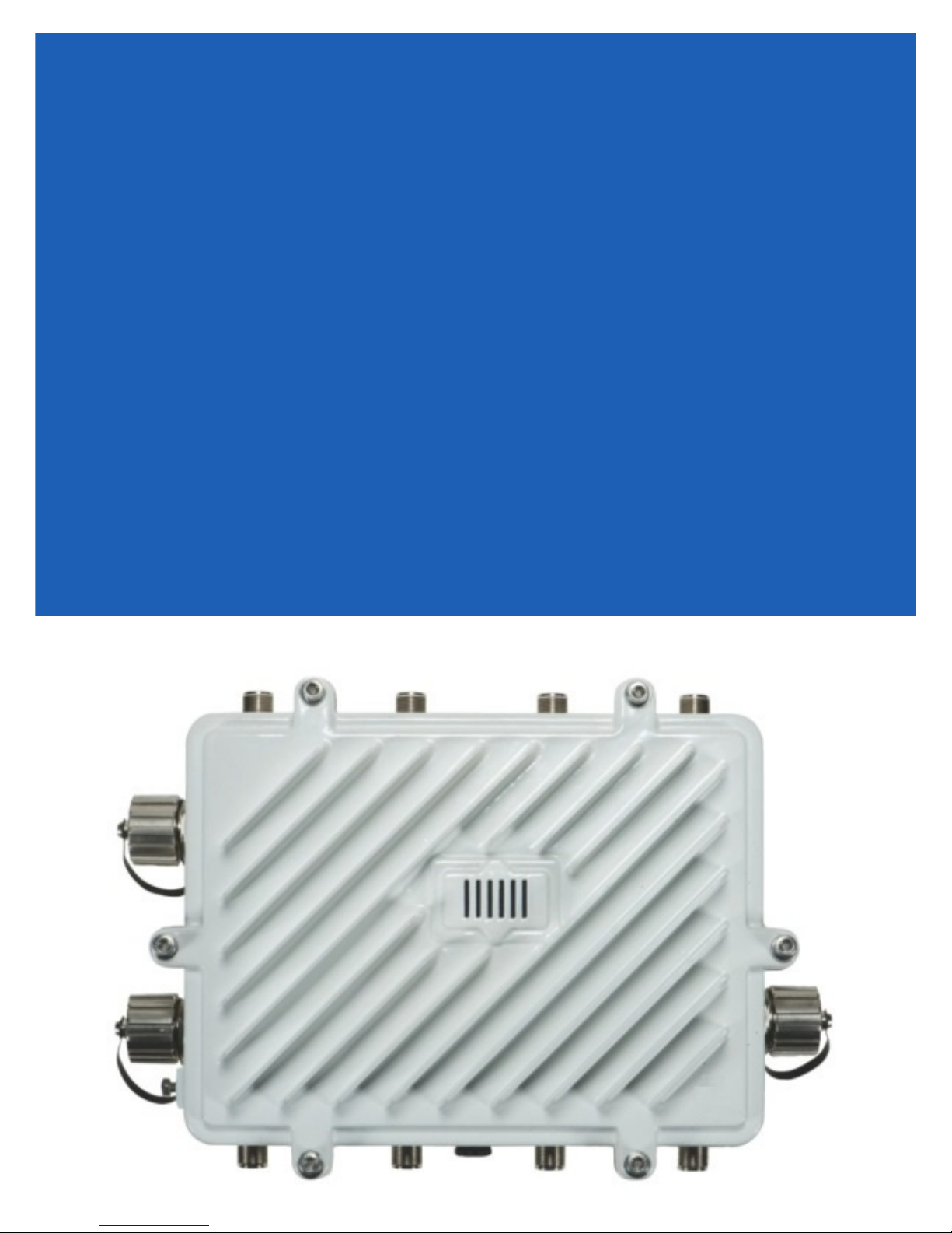
Perfect for extending network coverage to outside areas, the AP 7161 brings the latest 802.11n 3x3 Multiple Input
Multiple Output (MIMO) tri-radio design together with rugged outdoor performance. True perimeter security is
provided using either a dedicated dual band sensor or software mode for both 2.4GHz and 5GHz bands to deliver
24x7 rogue detection and termination. The AP 7161 is optimized with WiNG 5 intelligence, extending QoS,
security, and mobility services to the Access Point to support better capacity and performance. The AP 7161 is
ideal for industrial, enterprise campus, video surveillance, public safety, and smartgrid utility deployments to
extend to the outdoors.
Deployments can be managed using the WiNG 5 architecture. The WiNG 5 architecture is a solution designed for
802.11n networking. It leverages the best aspects of independent and dependent architectures to create a smart
network that meets the connectivity, quality, and security needs of each user and their applications based on the
availability of network resources, including wired networks. WiNG 5 is a Third Generation WLAN solution which
incorporates the best of both the first generation Autonomous Access Point WLAN and the second generation
Centralized Controller Based WLAN. The AP 7161 Vehicle Mounted Modem (VMM) is a software enabled profile
within the WiNG 5 architecture that uses the same hardware as
AP 7161 infrastructure models.
The control plane is now distributed between the Access Points and the controllers. The network administrator
has the flexibility of directing the data plane either being forwarded directly from the Access Points, or via the
controllers. By distributing intelligence and control between the wireless controllers and APs, the WiNG 5
network can route directly via the best path, as determined by factors including the user, the location, the
application, and the available wireless and wired resources.
Once adopted by a RFS4000, RFS6000, RFS7000, or NX 9000 series controller, the AP 7161 is managed as an
Adaptive AP running the WiNG 5 network management protocol. WiNG 5 networks extend the current
differentiation that Adaptive APs offered to the next level by now having the services and security available at
every point in the network. The traffic flow is optimized to prevent wired congestion, as well as wireless
congestion. Traffic flows dynamically, based on user and application, and finds alternate routes to work around
any possible network choke points. Mixed-media application optimization is the hallmark of WiNG 5 networks.
Extending the indoor network to the outdoors increases the need to guard against unwanted intruders and
attackers, and monitor network performance and availability. In addition to industry standard security for clients
and radio backhaul, the AP 7161 provides true perimeter security using either a dedicated dual band sensor or
software mode in the 2.4GHz and 5Ghz bands. Concurrent around-the-clock dual band Network Assurance sensing
and wireless traffic is provided together with spectrum analysis, eliminating the need for separate devices.
An Access Point can function as a Wireless Intrusion Protection System (WIPS) sensor and upload sensor mode
operation information to a dedicated WIPS server. WIPS protects your wireless network, mobile devices, and
traffic from attacks and unauthorized access. WIPS provides tools for standards compliance and around-the-clock
802.11a/b/g wireless network security in a distributed environment. WIPS allows administrators to identify and
accurately locate attacks, rogue devices, and network vulnerabilities in real time and permits both a wired and
wireless lockdown of wireless device connections upon acknowledgment of a threat.
Page 7
Installation Guide 7
!
Capacity in video surveillance solutions is critical to the performance of many networks designed to monitor and
provide safety. To assist with the deployment of video surveillance networks where the camera application
resides, the AP 7161 offers band unlocked radio flexibility. The user can choose between 2.4Ghz, 5Ghz and 4.9Ghz
bands for the radio type. The AP 7161 supports 3x3 MIMO technology, reaching a maximum data rate of 300 Mbps
to maintain high performance and better quality of transmission.
The AP 7161 is designed to optimize network availability through preemptive intelligence which dynamically
senses weak or failing signals, securely moves mobile users to alternate APs, and boosts signal power to
automatically fill RF holes and ensure uninterrupted mobile user access.
The AP 7161 band unlocked radios allow flexibility and deployment options for the public safety market. The
powerful radio increases coverage, performance, and obstruction penetration for outdoor use. Receiver sensitivity
is increased proportionally so users have an increased ability to maintain high performance access for mobility
and client devices in the network.
1.1 Document Conventions
The following graphical alerts are used in this document to indicate notable situations:
NOTE Tips, hints, or special requirements that you should take note of.
CAUTION Care is required. Disregarding a caution can result in data loss or equipment
malfunction.
WARNING! Indicates a condition or procedure that could result in personal injury or equipment
damage.
1.2 AP 7161 Hardware
There are currently four AP 7161 Access Point infrastructure models.
Model Part Number Description
AP-7161-66040-US AP 7161 OUTDOOR DUAL RADIO 802.11N AP US
AP-7161-66040-WR AP 7161 OUTDOOR DUAL RADIO 802.11N AP INTL
AP-7161-66040-EU AP 7161 OUTDOOR DUAL RADIO 802.11N AP EU
AP-7161-66S40-US AP 7161 OUTDOOR DUAL RADIO 802.11N AP W/SENSOR US
Page 8
8 AP 7161 Access Point
Model Part Number Description
AP-7161-66S40-WR AP 7161 OUTDOOR DUAL RADIO 802.11N AP W/SENSOR INTL
AP-7161-66S40-EU AP 7161 OUTDOOR DUAL RADIO 802.11N AP W/SENSOR EU
AP-7161-66S40-JP AP 7161 OUTDOOR DUAL RADIO 802.11N AP W/SENSOR JP
The AP 7161 Vehicle Mounted Modem (VMM) is a software profile within the WiNG 5 architecture that uses the
same hardware as the AP 7161 Access Point infrastructure models.
1.3 AP7161 Antenna Accessories
NOTE Antennas must be ordered separately. They are not included with the AP 7161.
The AP 7161 antenna suite includes the following optional antenna accessories. The antennas do not ship with
the AP 7161 models listed in the table above and must be ordered separately.
Page 9

Installation Guide 9
1.3.1 AP 7161 4.9 GHz and 5 GHz Antennas
Part Number Band Gain
ML-5299-HPA10-01 4.9-5.8 10 19.5 Outdoor rated
ML-5299-HPA5-01 5.2-5.8 5 6.75 Outdoor rated
ML-5299-FHPA6-01 4.9-5.8 8 11 Outdoor rated
Height
(inches)
Type: dipole
Gain: 10dBi@4.9GHz
Connector: N-male
Type: dipole
Gain: 5dBi@5.0GHz
Connector: N-male
Type: dipole
Gain: 8dBi@4.9-5.8GHz
Connector: N-male
1.3.2 AP 7161 Multi Band Antennas
Description
Part Number Band Gain
ML-2452-HPAG5A8-01 2.4-5.8 4.5/7.5 11 Outdoor rated
ML-2452-VMM3M3-036 2.4-5.8 3.6/4.0 1.5 Outdoor rated
NOTE The ML-2452-HPAG5A8-01 multi band antenna is suggested for use with AP 7161
Height
(inches)
Type: dipole
Gain: 4.5dBi@2.4GHz, 7.5dBi@5GHz, 5.5dBi@4.9GHz
Connector: N-male
Vehicle Mounted MIMO Omni Patch
Type: VMM
Gain: 3.6dBi (typical) to 4.5dBi (maximum) @2.4GHz,
4.5 (typical) to 5.4 (maximum) @5.8GHz
Connector: RP-SMA male
sensor models AP-7161-66S40-US and AP-7161-66S40-WR on ports R3-A and R3-B,
respectively. The
ML-2452-VMM3M3-036
is suggested for use with AP 7161 VMM. Three
connections to the radio on either R1 or R2 are required for mobile operation.
Description
Page 10

10 AP 7161 Access Point
1.3.3 AP-7161-66S40-JP Antennas
Part Number Band Gain
Height
(inches)
ML-2452-HPAG5A8-01 2.4-5.8 4.5/7.5 11 Outdoor rated
Type: dipole
Gain: 4.5dBi@2.4GHz, 7.5dBi@5GHz, 5.5dBi@4.9GHz
Connector: N-male
ML-2452-VMM3M3-036 2.4-5.8 3.6/4.0 1.5 Outdoor rated
Vehicle Mounted MIMO Omni Patch
Type: VMM
Gain: 3.6dBi (typical) to 4.5dBi (maximum) @2.4GHz,
4.5 (typical) to 5.4 (maximum) @5.8GHz
Connector: RP-SMA male
ML-2452-HPA6X6-036 2.4-5.8 4.0/6.0 4.5 Outdoor rated
Type: six port omni dipole array (3x2.4G, 3x5G)
Connector: Type N male x6
ML-5299-HPA1-01R 4.9-5.8 6.0 11 Outdoor rated
Type: dipole array
Connector: RP-SMA male
Description
Page 11

Installation Guide 11
1.4 Outdoor PoE Hardware and Mounting Accessories
The AP 7161 is a Power over Ethernet (PoE) device. When deployed, the use of an outdoor rated PoE power supply
and mounting bracket may be required. The recommended PoE accessories are listed in the following table. For
more information, see
Part Number Description
AP-PSBIAS-7161-US Outdoor IP66 802.3AT gigabit Ethernet power injector, 100-240 VAC US
AP-PSBIAS-7161-WW Outdoor IP66 802.3AT gigabit Ethernet power injector, 100-240 VAC
KT-153143-01 Outdoor PoE mounting kit
AP 7161 Power Options Using Power over Ethernet on page 45.
International
1.5 AP 7161 Mounting Accessories
The AP 7161 has a flexible three piece mounting kit (
KT-150173-01)
arm (
information, see
Part Number Description
KT-147407-01 AP 7161 mounting hardware kit
KT-150173-01 AP 7161 12 inch extension arm for mounting kit
KT-158767-01 AP 7161 vehicle mount
for pole mounting. When deployed as a VMM, use the vehicle mount kit (
AP 7161 Hardware Mounting and Installation on page 23.
KT-147407-01)
, together with an optional standoff extension
KT-158767-01).
For more
1.6 AP 7161 Weatherized Ethernet Accessory
One RJ45 weatherized connector plug is included with each AP 7161 Access Point. If additional plugs are
required, they can be ordered using the part number listed in the following table:
Part Number Description
KT-153676-01 AP 7161 RJ45 weatherized Ethernet plug
Page 12

12 AP 7161 Access Point
1.7 Package Contents
Carefully remove all protective packing material from around the AP 7161 Access Point and save the container for
later storage and shipping. Refer to
been received.
Record the serial numbers on the shipping cartons and AP 7161 Access Points for warranty claims
and reference during software download procedures.
NOTE Record the serial numbers on the shipping cartons and AP 7161 Access Points for
warranty claims and reference during software download procedures.
When opening the shipping cartons, inspect the equipment for damage. If you find any damaged equipment or any
equipment is missing, contact Support immediately.
AP 7161 Hardware on page 7 when verifying that all AP 7161 hardware has
Each AP 7161 model number (see
AP 7161 Hardware on page 7) includes the following parts:
• AP 7161 Access Point
• Weatherproof RJ45 plug kit
• AP 7161 Access Point Installation Guide (this document)
The following items are not included with the AP 7161 Access Point models but can be ordered separately:
• Antennas
• Mounting brackets/kits
• PoE power supply and accessories
• RFS controllers (if required)
The following items are not provided and can be sourced from local hardware suppliers, partners, or distributors:
• Lightning protection unit
• Cat5E cable to connect power source
• Band clamps, lag bolts, or U-bolts
• Grounding wire
• Self-healing weatherproofing tape
When opening the shipping cartons, inspect the equipment for damaged or missing parts (see
on page 7
). If you find any damaged or missing equipment, contact your distributor, partner, or Support
immediately.
For items that are not provided, contact your local hardware suppliers.
AP 7161 Hardware
Page 13
Installation Guide 13
!
!
1.8 Hardware Installation Guidelines
CAUTION All device wiring must comply with the National Electric Code (NEC) or regulations
and procedures defined by the regulatory bodies of the country or region where the
devices are being deployed. All local building and structure codes must be
observed.
WARNING! Strictly observe the following safety precautions and warnings when installing an AP
7161 Access Point.
1.8.1 Precautions
Before installing an AP 7161 model Access Point, verify the following grounding and lightning protection notes:
• The installation professional should be familiar with all grounding requirements and regional codes and
ensure that the Access Point and mounting asset are properly grounded. The grounding cable for an AP
7161 must be at a minimum a #10 gauge wire cross section. The cable can be attached to the unit using
one of the following methods:
• Loosen the grounding screw, insert the grounding cable into the hole below it, and tighten the screw.
• Loosen the grounding screw, wind the grounding cable around it, and tighten the screw.
• Attach a ring lug to the grounding cable and secure it to the unit using the grounding screw.
• To properly attach the grounding cable to the Access Point, refer to
• For Ethernet and lightning protection, it is recommended that a commercially available off-the-shelf
Lightning Protection Unit (LPU) be used on all shielded CAT5E Ethernet connections. The LPU should be
rated for outdoor use.
• For the best possible protection, each Access Point requires an LPU be installed adjacent to the Access
Point. If there is a LAN connection to an indoor network, a second LPU is required at the cable entry
point to the building.
CAUTION Lightning damage is not covered under the conditions of a standard product
warranty. When installed correctly, Lightning Protection Units (LPUs) provide the
best protection from the harmful effects of lightning. Observe all regional and
national codes that apply for lightning protection.
• Verify that the deployment environment has a continuous temperature range compatible with the
operating temperature range of the device.
AP 7161 Grounding Screw on page 19.
Page 14

14 AP 7161 Access Point
!
1.8.2 Warnings
• Read all installation instructions and site survey reports, and verify correct equipment installation before
connecting the Access Point to its power source.
• Remove jewelry and watches before installing this equipment.
• Verify that the unit is grounded before connecting it to the power source.
• Verify that any device connected to this unit is properly wired and grounded.
• Connect all power cords to a properly wired and grounded electrical circuit. Verify that the electrical
circuits have appropriate overload protection.
• Attach only approved power cords to the device.
• Verify that the power connector and socket are accessible at all times during the operation of the
equipment.
• Do not hold any component containing a radio such that it is very close to or touching any exposed parts
of the body, especially the face or eyes, while transmitting.
• Do not work with power circuits in dimly lit spaces.
• Do not install this equipment or work with its power circuits during thunderstorms or other weather
conditions that could cause a power surge.
• Verify there is adequate ventilation around the device, and that ambient temperatures meet equipment
operation specifications.
• Avoid contact with overhead power lines.
• Take precautions to avoid injury from falling tools and equipment. Crews should wear hard hats in and
around the installation work site.
• Be aware of vehicular traffic in and around the installation work site.
• Do not operate a portable transmitter near unshielded blasting caps or in an environment where
explosives are present unless the transmitter is especially certified for such use.
• Refer to your site survey and network analysis reports to determine specific requirements for each
deployment.
• Assign installation responsibility to the appropriate personnel.
• Identify and document where all installed components are located.
• Identify and prepare Ethernet and console port connections.
• Verify that cable lengths are within the maximum allowable distances for optimal signal transmission.
CAUTION The maximum length allowed for PoE cables is 100 meters.
Page 15
Installation Guide 15
1.9 Access Point Placement
Observe the following recommended guidelines to help ensure a successful network deployment:
• Identify all pieces of the mounting bracket and mounting extension arm hardware and ancillary hardware
AP 7161 Hardware on page 7).
(see
• Mount the device with the black gore vent down.
• Mounting height for network devices should not exceed 30 to 35 feet. Mounting height should vary to
accommodate the topography of the deployment area, foliage, and other obstructions.
• Devices can be deployed using any of the recommended outdoor deployment procedures.
• Line of Sight (LoS) guidelines should be given special consideration when deploying devices.
1.10 AP 7161 Hardware Overview
AP 7161 models can be purchased in a two or three radio configuration (see AP 7161 Hardware on page 7). Each
model has two band unlocked radios that can operate across the 2.4GHz, 4.9GHz, and 5GHz bands, subject to
country regulatory approval and outdoor/band use.
An AP 7161 must be installed by trained professionals familiar with RF planning and regulatory limits defined by
the regulatory bodies of the country where the devices are being deployed. All common precautions for grounding
and Electrostatic Discharge (ESD) protection should be observed during deployment and installation. AP 7161
Access Points must be installed such that no harmful interference results from device operation.
1.10.1 AP 7161 Ports and Connections
The AP 7161 Access Point has the following port designations:
• Antenna ports R1-A, B and C, R2-A, B and C, and R3-A and B
• Console port
• GE1/POE - LAN port
• GE2 - WAN port
The following sections describe the ports and connections for the AP 7161.
Page 16
16 AP 7161 Access Point
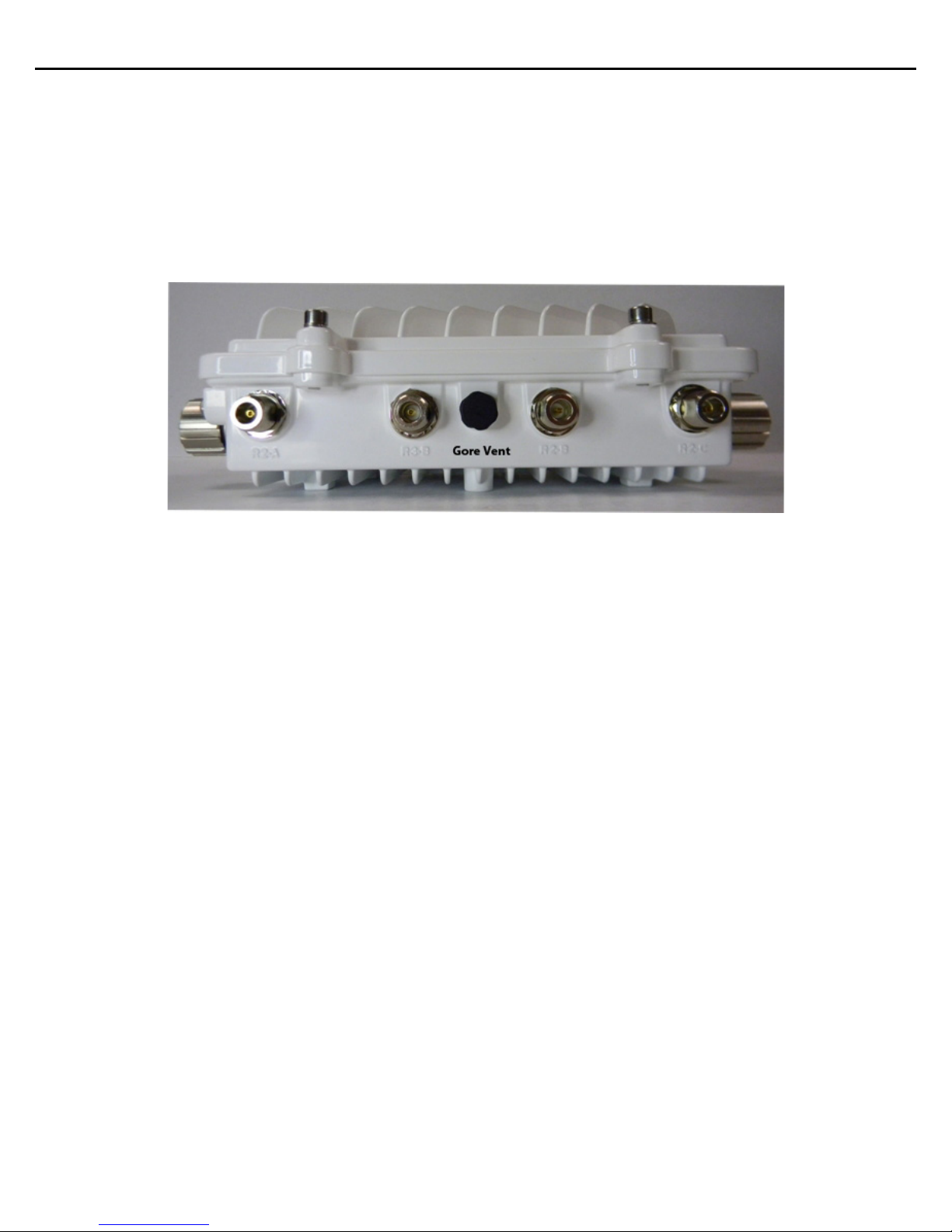
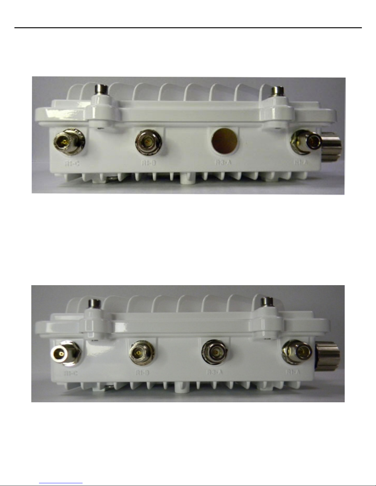
1.10.2 AP 7161 Antenna Connectors
AP 7161 two radio models (AP-7161-66040-US and AP-7161-66040-WR) are configured with six N type connectors
to support two active WLAN data radios.
When mounting antennas to ports R1-A, R1-B, and R1-C, ensure that you have selected the appropriate band for
the configured radio that uses ports R1-A, R1-B, and R1-C. In this instance, R1 ports relate to the software
configured radio 1 settings.
When mounting antennas to connectors marked R2-A, R2-B and R2-C, these antenna ports relate to the software
settings of radio 2. Care must be taken to provide the correct antenna for the operating band of each port.
AP 7161 three radio models (AP-7161-66S40-US and AP-7161-66S40-WR) are configured with eight N type
connectors to support two active WLAN data radios and a dedicated sensor radio as the third.
As with the two radio models, R1 ports relate to the software configured radio 1 settings. When mounting
antennas to connectors marked R2-A, R2-B and R2-C, the antenna ports relate to the software configured radio 2
settings. Care must be taken to provide the correct antenna for the operating band of each port.
Page 17
Installation Guide 17
Ports R3-A and R3-B are reserved for the sensor radio. An appropriate multi band antenna should be mounted on
the unit for sensor operation.
NOTE The sensor radio does not function as a WLAN data radio.
WARNING! Antenna ports where no antenna is mounted must be properly terminated using an
approved IP67 terminator.
WARNING! All antenna connectors should be covered with weatherproofing tape.
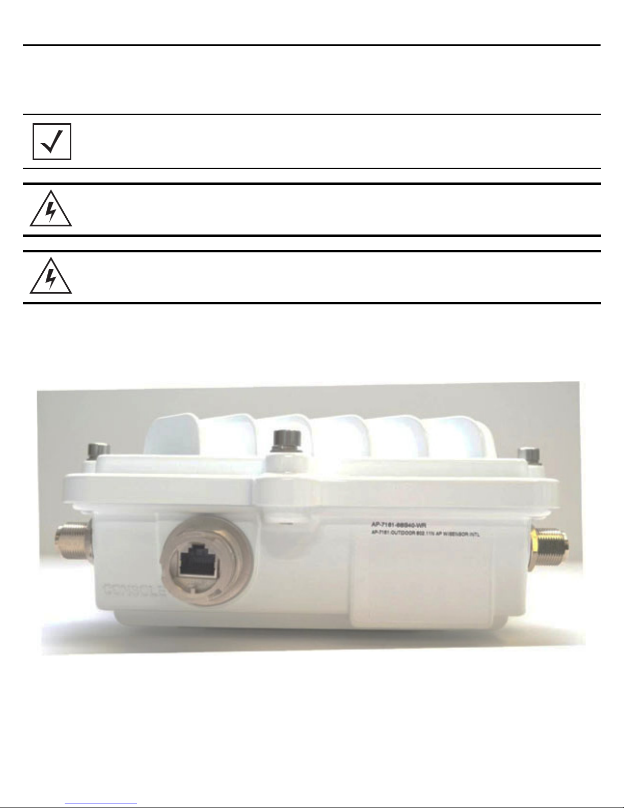
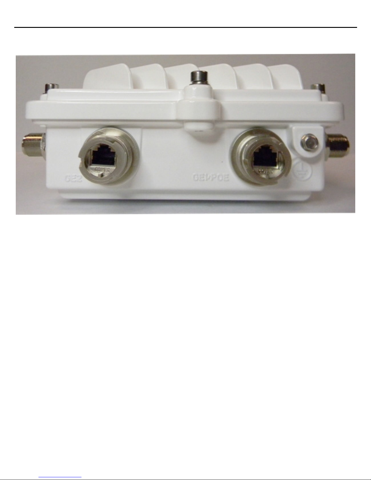
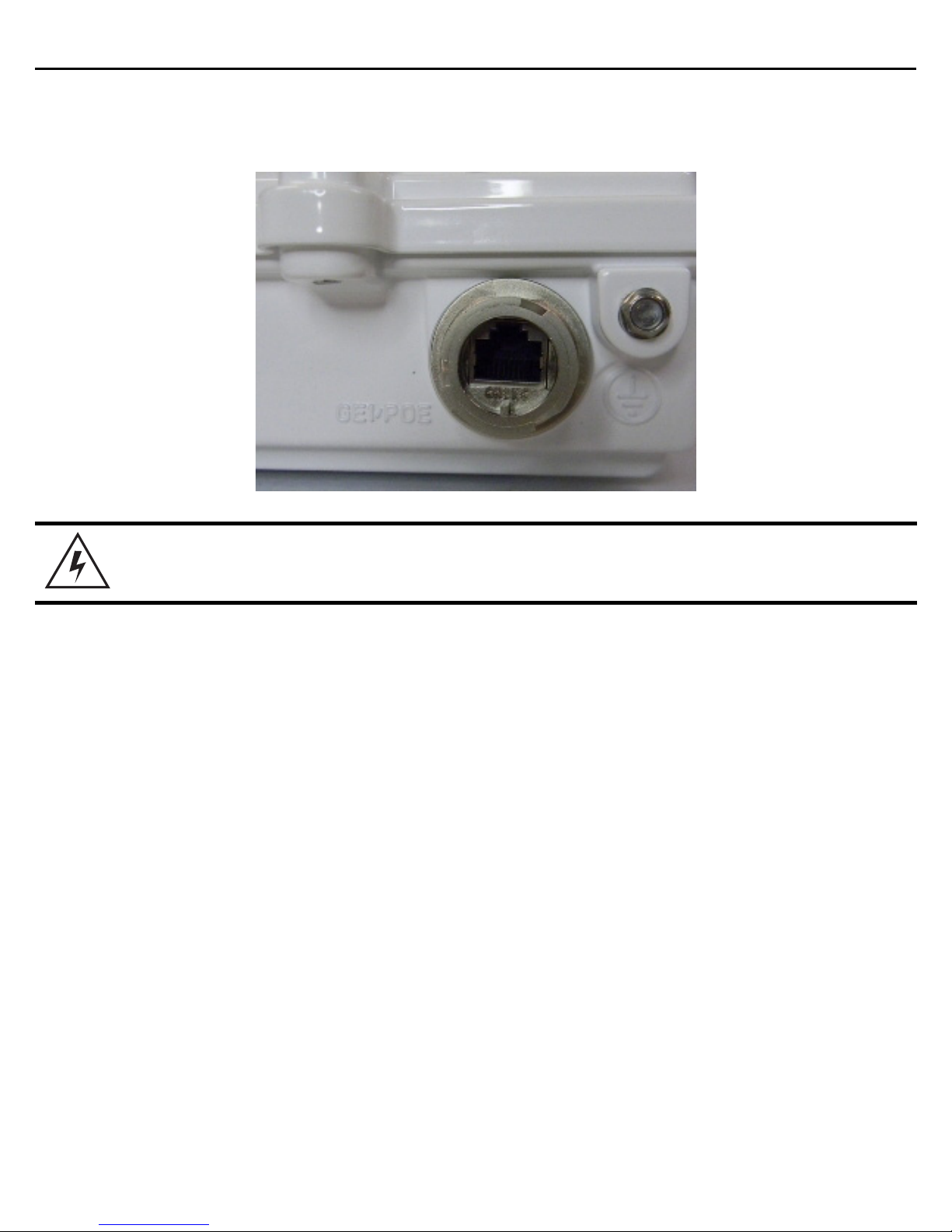
1.10.3 AP 7161 Console, GE1/POE and GE2 Ports
The AP 7161 has Ethernet ports for external console, GE1/POE, and GE2 connections.To gain access to the ports
you will need to remove the protective caps.
Page 18
18 AP 7161 Access Point
The Ethernet cable from the PoE device (if used) connects to the GE1/POE port on the unit.
The GE2 port on the unit can be used if a second data connection for an external device (e.g. surveillance camera)
is required. Ensure the GE2 WAN port has been configured to permit an attached external device during the
configuration process.
When making connections using these ports, a properly rated RJ45 connector is required. One weatherproof RJ45
plug kit is provided with each Access Point. When connecting cables to the AP 7161 Ethernet ports, follow the
instructions in the connector packaging and tighten the connectors to create a weatherproof seal. Shielded cables
are required.
Page 19
Installation Guide 19
1.10.4 AP 7161 Grounding Screw
The grounding screw is located to the right of the GE1/POE port and above the GND symbol.
WARNING! The grounding cable for an AP 7161 must be at a minimum a #10 gauge wire cross
section.
The grounding cable can be attached to the unit using one of three recommended methods. Using an 8mm socket
and driver:
• Loosen the grounding screw and insert the grounding cable into the hole below it. Tighten the grounding
screw to 30 inch pounds (lbf-in).
• Loosen the grounding screw and wind the grounding cable around the screw. Tighten the grounding screw
to 30 inch pounds (lbf-in).
• Attach a ring lug to the grounding cable and remove the grounding screw to attach the ring lug to the
Access Point. Secure it to the unit by reinserting the grounding screw. Tighten the grounding screw to 30
inch pounds (lbf-in).
Page 20

20 AP 7161 Access Point
1.11 LED Indicators
The AP 7161 Access Point has six LEDs on the top of the Access Point housing. When the Access Point is
positioned with the logo in the lower right corner, LED 1 is on the left and LED 6 is on the right.
The Access Point utilizes two different colored lights below each LED. Only one light displays within an LED at any
given time. Every light within each LED is exercised during startup to allow the user to see if an LED is not
functioning. The LEDs turn on and off while rotating in a circular pattern. Since two LEDs feed each light pipe, the
pattern is from left to right (LEDs 1 through 6), then right to left (LEDs 6 through 1).
Page 21

Installation Guide 21
The top housing LEDs have the following display patterns and functionality:
1.11.1 Two Radio LEDs
A two radio model Access Point (P/N AP-7161-66040-US and AP-7161-66040-WR) has the following unique LED
behavior:
LED 1
(Sensor)
Not Used Blinking
LED 2
(2.4 GHz)
Emerald
indicates
802.11b/g/n
activity.
Solid
Emerald
indicates a radio
is present but
not configured.
LED 3
(5 GHz)
Blinking
indicates
802.11a/n
activity.
Solid
indicates a radio
is present but
not configured.
Amber
Amber
LED 4
(GE2/WAN)
LED
Off
indicates the
port is not
connected.
Blinking
indicates
normal
operation.
Rapidly blinking
Yellow
indicates a port
error.
Green
LED 5
(GE1/LAN)
LED
Off
indicates the
port is not
connected.
Blinking
indicates
normal
operation.
Rapidly blinking
Yellow
indicates a port
error.
Green
LED 6
(System)
Solid
Red
indicates
diagnostic mode.
Blinking
second interval
indicates POST
failure.
Solid
White
following
diagnostic
mode
indicates
booting.
Blinking
White
at 1
second interval
indicates “no
adoption”.
Red
Red
at 1
and
WARNING! If LED 6 remains blinking Red for longer than 10 minutes, cycle the power to the
unit. If the condition persists, contact the Support center.
Solid
White
indicates normal
operation.
Page 22

22 AP 7161 Access Point
1.11.2 Three Radio LEDs
A three radio model Access Point with sensor (P/N AP-7161-66S40-US and AP-7161-66S40-WR) has the following
unique LED behavior:
LED 1
(Sensor)
Blinking
Emerald
Amber
second interval
indicates a radio
is present but
not connected to
a server.
Solid
indicates a radio
is present and
connected to a
server.
and
at 2
Amber
LED 2
(2.4 GHz)
Blinking
Emerald
indicates
802.11b/g/n
activity.
Solid
indicates a radio
is present but
not configured.
Emerald
LED 3
(5 GHz)
Blinking
indicates
802.11a/n
activity.
Solid
indicates a radio
is present but
not configured.
Amber
Amber
LED 4
(GE2/WAN)
LED
Off
indicates the
port is not
connected.
Blinking
indicates
normal
operation.
Rapidly blinking
Yellow
indicates a port
error.
Green
LED 5
(GE1/LAN)
Off
LED
indicates the
port is not
connected.
Blinking
indicates
normal
operation.
Rapidly blinking
Yellow
indicates a port
error.
Green
LED 6
(System)
Red
Solid
indicates
diagnostic mode.
Blinking
1 second interval
indicates POST
failure.
Solid
White
following
diagnostic
mode
indicates
booting.
Blinking
White
at 1
second interval
indicates “no
adoption”.
Red
Red
at
and
Solid
White
indicates normal
operation.
Page 23
Installation Guide 23
2 AP 7161 Hardware Mounting and Installation
It is recommended to use the AP 7161 mounting bracket kit (KT-147407-01) for most deployments. When a
standoff distance is required for a pole mounted or wall mounted installation, use the extension arm kit
(KT-150173-01).
The following sections detail the installation procedure for deploying an AP 7161 Access Point.
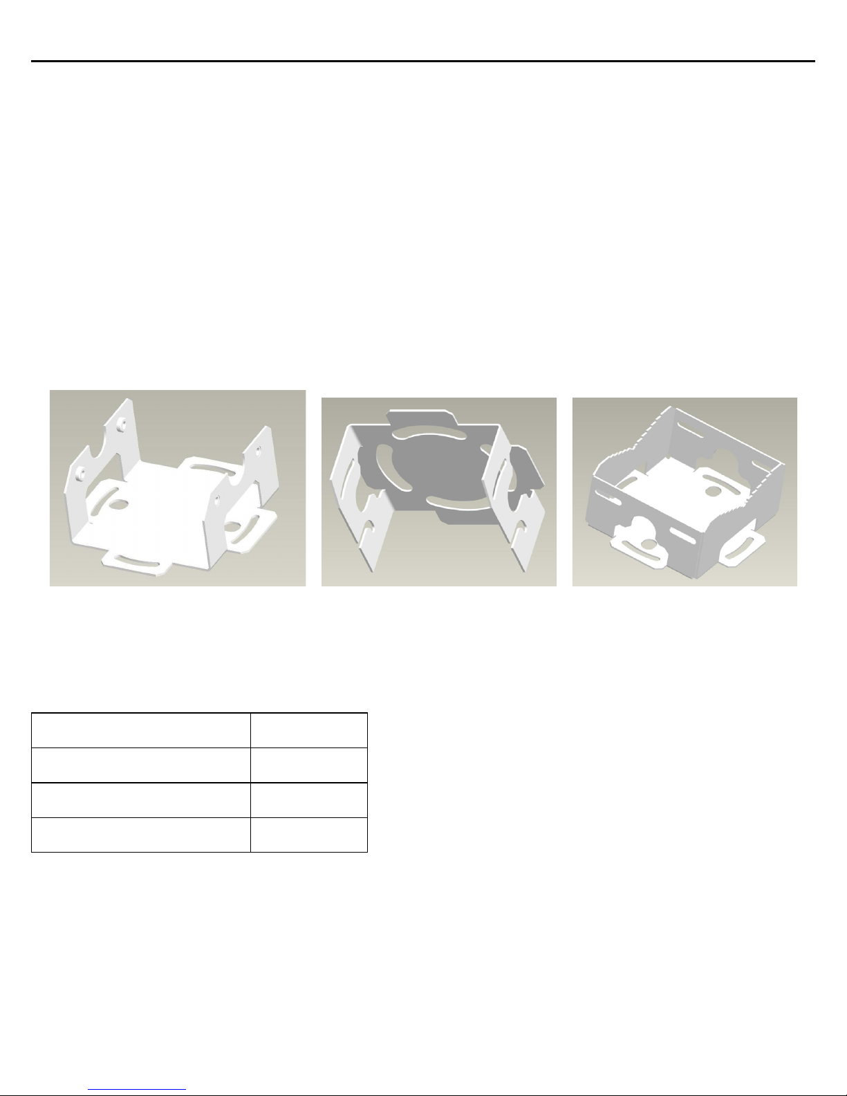
2.1 Mounting Bracket Kit
The AP 7161 mounting bracket kit (KT-147407-01) includes the Access Point bracket (left), angle adapter bracket
(center), and pole mount bracket (right) sections:
The Access Point bracket and angle adapter bracket can be rotated (plus or minus 15 degrees) and tilted (up to 45
degrees) to orient the unit for optimal positioning.
The following ancillary hardware to assemble the mounting bracket sections is included in the kit:
Description Quantity
M6 serrated hex flanged screws 8
1/2 inch hex head nut 2
1/2 inch x 3/4 inch hex head bolt 2
Page 24
24 AP 7161 Access Point
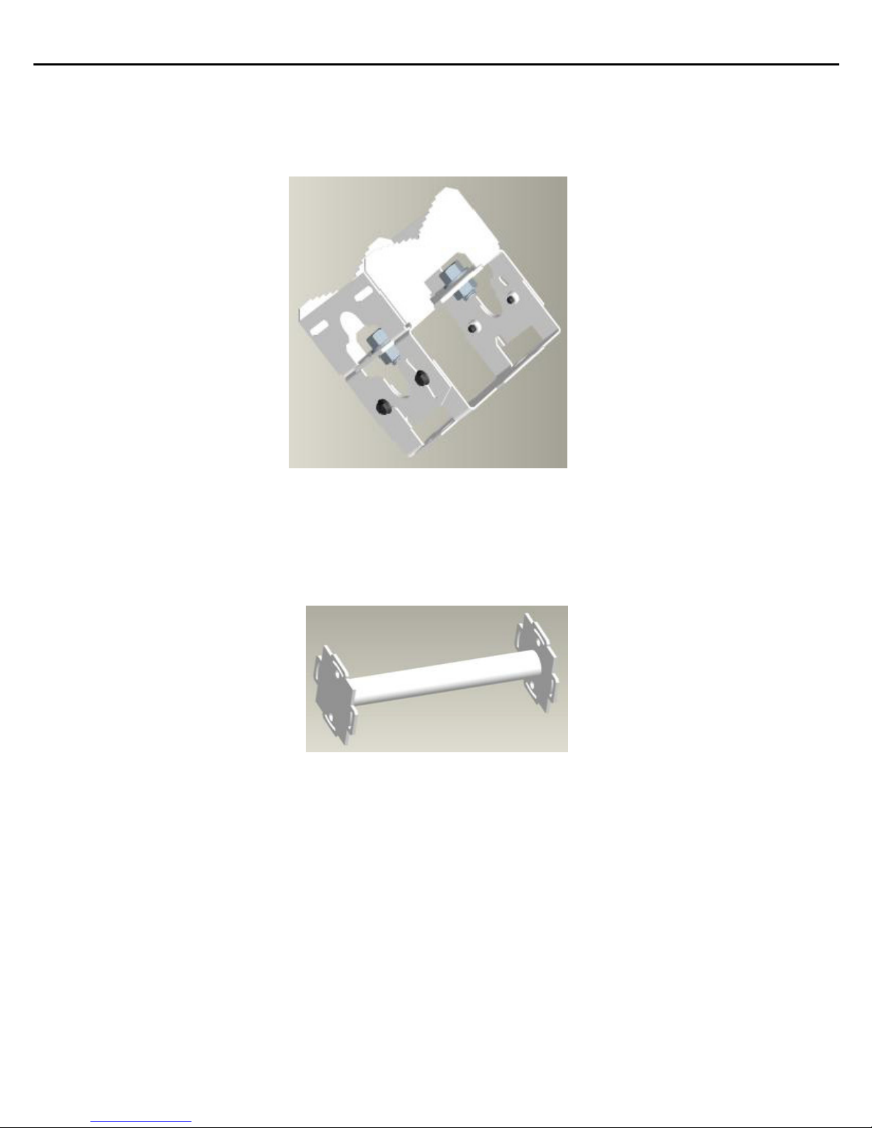
A torque wrench or ratchet with a 10mm adapter, or an adjustable wrench, can be used to assemble the mounting
brackets. A finished assembly of the mounting bracket kit is shown below. Assembly during deployment may
differ to achieve the required angle and rotation.
2.1.1 Extension Arm Kit
When mounting an AP 7161 on poles more than 3 inches in diameter, use the extension arm kit (KT-150173-01) to
provide a minimum standoff distance of twelve inches to avoid interference with the antennas.
Page 25

Installation Guide 25
The extension arm kit can also be used in combination with the any of the brackets from the mounting bracket kit.
The following ancillary hardware to attach the extension arm to the mounting bracket kit sections is included in
the extension arm kit:
Description Quantity
1/2 inch hex head nut 2
1/2 inch x 3/4 inch hex head bolt 2
Page 26
26 AP 7161 Access Point
!
2.2 Pole Mounted Installations
The mounting hardware kit and extension arm can be used in various combinations to properly install the AP 7161
on a pole. For poles of up to 3 inches in diameter, attach the pole mount bracket of the mounting hardware kit at
the desired position on the pole using band clamps up to 3/4 inch width, or a 1/2 inch x 4 inch wide U-bolt and
nuts. For poles greater than 3 inches in diameter, attach the pole mount bracket using band clamps.
CAUTION Always mount the AP 7161 with the black gore vent facing down.
NOTE The U-bolt and band clamps are not included in the mounting bracket kit.
NOTE Use of the extension arm is recommended for installations on poles greater than 3
inches in diameter.
2.2.1 Vertical Pole Mount
Use the following procedure for vertical pole mount installations. The extension arm is recommended when
mounting the Access Point to poles greater than 3 inches is diameter.
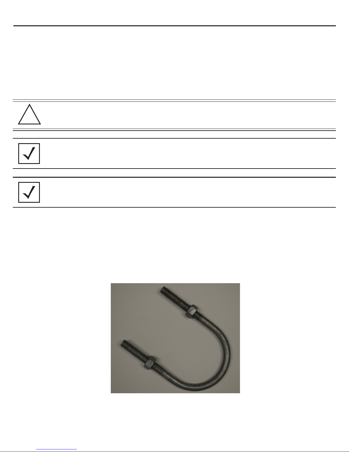
For poles up to 3 inches in diameter when using a U-bolt:
1. Thread two 1/2 inch nuts onto the U-bolt.
Page 27

Installation Guide 27
2. Position the U-bolt on the pole and place the pole mount bracket section on the U bolt. Adjust the two 1/2
inch inner nuts until the pole mount bracket section is against the pole and the U-bolt can be secured
tightly to the pole at the desired mounting location.
3. Place the angle adapter bracket section on the U-bolt with the open slot connections on the bottom and
align it with the pole mount section. Attach with two 1/2 inch nuts. Tighten all nuts to 300 inch pounds
(lbf-in).
Page 28

28 AP 7161 Access Point
4. Position the Access Point bracket section so that the bottom of the section with the straight (not bevel cut)
side is oriented toward the bottom side of the AP with the gore vent. Using a torque wrench or a ratchet
and a 10mm socket, or an adjustable wrench, attach (but don’t tighten) the Access Point bracket section
to the AP 7161 with the four M6 flange screws
5. Insert two M6 hex flange screws into the bottom holes on the sides of the Access Point bracket section.
Page 29

Installation Guide 29
6. With the Access Point positioned so that the gore vent is facing down, insert the two M6 hex flange
screws in the bottom holes on the sides of the Access Point bracket section into the open slot connections
on the bottom of the angle adapter bracket section.
7. Rotate the Access Point bracket section upward and align the top holes on the sides with the top holes
on the angle adapter bracket section. Insert two M6 hex flange screws into the top holes on the angle
adapter bracket section.
8. Use a torque wrench or a ratchet and a 10mm socket, or an adjustable wrench, to finish attaching the
Access Point bracket section to the angle adapter bracket section with the M6 hex flange screws in the
open slot connections and the top holes on the angle adapter bracket section. Do not tighten the screws
until all rotation and tilt adjustments are complete.
9. To adjust the position of the Access Point, rotate the Access Point bracket section (plus or minus 15
degrees) and tilt the angle adapter bracket section (up to 45 degrees).
10. Tighten all hex flange screws to 60 inch pounds (lbf-in).
Page 30

30 AP 7161 Access Point
For mounting with band clamps:
1. Attach the pole mount bracket section at the desired mounting location using band clamps.
2. With the angle adapter bracket section positioned so that the open connector slots are on the bottom,
attach the angle adapter bracket section to the pole mount bracket section using two 1/2 inch bolts and
nuts. Tighten the nuts to 30 inch pounds (lbf-in).
Page 31

Installation Guide 31
3. Position the Access Point bracket section so that the bottom of the section with the straight (not bevel cut)
sides is oriented toward the bottom side of the AP with the gore vent. Using a torque wrench or a ratchet
and a 10mm socket, or an adjustable wrench, attach (but don’t tighten) the Access Point bracket section
to the AP 7161 with the four M6 hex flange screws.
4. Insert two M6 hex flange screws into the bottom holes on the sides of the Access Point bracket section.
Page 32

32 AP 7161 Access Point
5. With the Access Point positioned so that the gore vent is facing down, insert the two M6 hex flange
screws in the bottom holes on the sides of the Access Point bracket section into the open slot connections
on the bottom of the angle adapter bracket section.
6. Rotate the Access Point bracket section upward and align the top holes on the sides with the top holes
on the angle adapter bracket section. Insert two M6 hex flange screws into the top holes on the angle
adapter bracket section.
Page 33

Installation Guide 33
7. Use a torque wrench or a ratchet and a 10mm socket, or an adjustable wrench, to finish attaching the
Access Point bracket section to the angle adapter bracket section with the M6 hex flange screws in the
open slot connections and the top holes on the angle adapter bracket section. Do not tighten the screws
until all rotation and tilt adjustments are complete.
8. To adjust the position of the Access Point, rotate the Access Point bracket section (plus or minus 15
degrees) and tilt the angle adapter bracket section (up to 45 degrees).
9. Tighten all hex flange screws to 60 inch pounds (lbf-in).
To use the extension arm with the mounting hardware kit:
1. Attach the pole mount section at the desired mounting location using a U-bolt or band clamps.
2. Complete the steps for assembling and positioning the mounting bracket sections for poles less than or
greater than 3 inches. See
Vertical Pole Mount on page 26.
Page 34

34 AP 7161 Access Point
3. Using a torque wrench or a ratchet and a 10mm socket, or an adjustable wrench, attach the extension arm
to the Access Point bracket section with four M6 hex flange screws. The two oval holes must be
positioned on the short sides of the Access Point. Tighten the hex flange screws to 60 inch pounds (lbf-in)
the unit.
4. With the Access Point positioned so that the gore vent is facing down, attach the extension arm to the
Access Point bracket section with two 1/2 inch bolts and nuts. Tighten the nuts to 30 inch pounds (lbf-in).
Page 35

Installation Guide 35
!
An example of using the extension arm with only the pole mount bracket is shown below:
2.2.2 Wall Mounted Installations
For wall mounted installations, use only the Access Point bracket section and angle adjust bracket section if
required.
CAUTION Always mount the AP 7161 with the black gore vent facing down.
NOTE The U-bolt and band clamps are not included in the mounting bracket kit.
NOTE The lag bolts are not included in the mounting bracket kit.
Page 36

36 AP 7161 Access Point
1. With the open slot connections facing down, attach the angle adjust bracket section at the desired
mounting location using four #10/32 lag bolts.
2. Using a torque wrench or a ratchet and a 10mm socket, or an adjustable wrench, attach (but don’t tighten)
the Access Point bracket section to the AP 7161 with four M6 hex flange screws and insert two M6 hex
flange screws into the bottom holes on the sides of the Access Point bracket section.
3. With the Access Point positioned so that the gore vent is facing down, insert the two M6 hex flange
screws in the bottom holes on the sides of the Access Point bracket section into the open slot connections
on the bottom of the angle adapter bracket section. Rotate the Access Point bracket section upward and
Page 37

Installation Guide 37
align the top holes on the sides with the top holes on the angle adapter bracket section. Insert two M6
hex flange screws into the top holes on the angle adapter bracket section.
4. Use a torque wrench or a ratchet and a 10mm socket, or an adjustable wrench, to finish attaching the
angle adapter bracket section to the Access Point bracket section with the four M6 hex flange screws in
the open slot connections and the top holes on the angle adapter bracket section. Do not tighten the
screws until all rotation and tilt adjustments are complete.
5. To adjust the position of the Access Point, rotate the Access Point bracket section (plus or minus 15
degrees) and tilt the angle adapter bracket section (up to 45 degrees).
6. Use a torque wrench or a ratchet and a 10mm socket, or an adjustable wrench, to tighten all screws when
all adjustments are complete.
7. Tighten all hex flange screws to 60 inch pounds (lbf-in).
Page 38

38 AP 7161 Access Point
To use only the extension arm:
1. Using a torque wrench or a ratchet and a 10mm socket, or an adjustable wrench, attach the extension arm
to the Access Point with four M6 hex flange screws. The two oval holes must be positioned on the short
sides of the Access Point. Tighten the hex flange screws to 60 inch pounds (lbf-in).
2. Attach the extension arm directly to the wall with lag bolts for other appropriate fasteners.
Page 39

Installation Guide 39
To use the extension arm with the mounting hardware kit:
1. With the open slot connections facing down, attach the angle adjust bracket section at the desired
mounting location using four #10/32 lag bolts.
2. Complete the steps for assembling and positioning the angle adapter bracket and Access Point bracket
sections outlined above. See
Vertical Pole Mount on page 26.
Page 40

40 AP 7161 Access Point
3. With the Access Point positioned so that the gore vent is facing down, attach the extension arm to the
Access Point using four M6 hex flange screws. The two oval holes must be positioned on the short sides
of the Access Point. Tighten the hex flange screws to 60 inch pounds (lbf-in).
4. With the Access Point positioned so that the gore vent is facing down, attach the extension arm to the
Access Point bracket section with two ½ inch bolts and nuts. Tighten bolts to 300 inch pounds (lbf-in).
Page 41

Installation Guide 41
2.3 AP 7161 VMM Mounting and Installation
The AP 7161 Vehicle Mounted Modem (VMM) is a software enabled profile within the WiNG 5 architecture that
uses the same hardware as the AP 7161 Access Point infrastructure models (see
AP 7161 Hardware).
An AP 7161 Access Point operating as a
VMM can be permanently mounted in a vehicle. It provides mesh backhaul
access to a mesh infrastructure network to connect mobile data terminals, laptop computers, or any other device
that has either an Ethernet or 802.11 wireless capability. The VMM operates on Power over Ethernet (PoE) and is
rugged enough for installation in commercial and public safety vehicles for mobile deployments. It is recommended
to use the AP 7161 vehicle mount kit (KT-158767-01) for mobile deployments.
Page 42

42 AP 7161 Access Point
To install the AP 7161 Access Point VMM:
1. Position the AP 7161 VMM upside down with the eight screw holes facing upwards.
2. Put the flat plate on top of the VMM. Align the key hole and four screw holes on the flat plate with the
philips screw head and four screw holes on the VMM.
Page 43

Installation Guide 43
3. Put the chassis mount on the flat plate with the key hole and four screw holes aligned.
NOTE The screw heads on the chassis mount should be facing down.
4. Put the stiffener plate on the chassis mount with the key hole and four screw holes aligned.
Page 44

44 AP 7161 Access Point
1. Insert four screws with washers through the holes of the three plates and into the screw holes on the
bottom of the VMM.
2. Using a 5mm allen wrench or box wrench, tighten the screws to 150 inch pounds (lbf-in).
3. Set the VMM and top bracket sub-assembly aside
4. Locate the mount point position for the VMM in the vehicle. Ensure there is sufficient clearance for cables
and antennas. The surface should be metal (1.0 mm minimum thickness), hard plastic or plywood, and
capable of supporting the weight of the VMM and bracket assembly.
5. Attach the vehicle mount securely to the mount point with metal screws or bolts (not provided).
6. Securely attach the AP 7161 top bracket sub-assembly to the vehicle mount with the four pre-installed
thumb screws. Tighten the screws to 90 inch pounds (lbf-in) using a philips screwdriver or pliers.
7. Attach three RP-SMAF adapters (part number 25-90263-02R) to the N connectors on the active mobile
radio on the VMM. Radio 1 ports are labeled R1-A, R1-B, and R1-C. Radio 2 ports are labeled R2-A, R2-B,
and R2-C.
8. Attach the antennas to the adapters for each radio to be enabled.
9. Connect the CAT5E cable providing power to the RJ45 port labeled GE1/POE.
WARNING! Connecting power to any other port could damage the unit.
10. Select an Access Point Mode from the available options.
Page 45

Installation Guide 45
!
2.4 AP 7161 Power Options Using Power over Ethernet
Power over Ethernet (PoE) is the power source for an AP 7161 Access Point. For optimal performance, an AP 7161
can be powered by the following injectors and RFS controllers that support 802.AT PoE.
For installations requiring an outdoor PoE injector, the following options are recommended:
• AP-PSBIAS-7161-US
• AP-PSBIAS-7161-WW
The AP-PSBIAS-7161 is a 1-Port 802.3at PoE Gigabit Ethernet injector. The injector is IP66 rated for outdoor
deployments when used with the weatherproof kit supplied.
There are two power cord options for the AP-PSBIAS-7161 models. The AP-PSBIAS-7161-US comes equipped with
a cable with a standard three prong power plug. This plug can be removed by the installer if required when
connecting to an AC source. The AP-PSBIAS-7161-WW comes equipped with a cable with open leads. Mounting
kits are not supplied (see
numbers).
Outdoor PoE Hardware and Mounting Accessories on page 11 for mounting kit part
NOTE Product installation and mounting instructions are provided with the outdoor power
injector. Refer to the AP-PSBIAS-7161 Install Guide.
If located within 100 meters of the controller and a PoE port is available, the AP 7161 Access Point can also be
connected directly to one of the following controllers:
• RFS4000
• RFS6000
• RFS7000
• NX9000
•NX95xx
A standard CAT5E cable can be used to provide the connection to the AP 7161. The GE1/POE port on the AP 7161
is where the standard CAT5E cable will connect to the Access Point and use of the weatherproof RJ45 plug kit
that comes with the unit will maintain a weatherproof seal for outdoor installation at the ethernet port.
If a CAT5E cable is used to connect the Access Point to an RFS controller through a building egress, a suitable
lightning protection system should be considered. A professional installer should be consulted to identify an
appropriate system.
CAUTION When using controllers, the total power limits for the AP 7161 must be considered.
The two radio configuration draws less power than a three radio configuration. If
sufficient power is not available, the AP 7161 software will disable the third radio
and throttle back performance on all radio and Ethernet interfaces.
Page 46

46 AP 7161 Access Point
!
2.5 AP 7161 VMM Power Options
The AP 7161 Vehicle Mounted Modem (VMM) is a software enabled profile within the WiNG5 architecture that
uses the same hardware as AP 7161 infrastructure models (see
mounted AP 7161 operating as a
VMM within a vehicle or mobile asset requires a power source delivered via
Power over Ethernet (PoE). The same requirements and guidelines for Access Point power are in force as noted in
this installation manual. Refer to
Specifications on page 59 for operating voltage and operating current.
An AP 7161 operating as a VMM has the capability of being installed into a variety of vehicular and mobile
environments. As such, a professional certified installation partner should be consulted on appropriate power
sources and installation into a vehicle or mobile asset. A vehicular power source is not provided. No responsibility
is taken for any power source design operated outside of the allowed specifications for power of an AP 7161
running as an AP 7161 VMM.
CAUTION Exceeding these requirements can invalidate warranty.
AP 7161 Hardware on page 7). As such, a
The following table shows a number of potential power sources and corresponding industry options to power an
AP 7161 VMM:
Potential Vehicular/Mobile Power Sources Required Source
12V battery DC-DC convertor or DC PoE injector
24V battery DC-DC convertor or DC PoE injector
12V power plug DC PoE injector with power plug adapter
AC invertor in vehicle AC PoE injector
PoE switch in train or vehicle Direct connection via CAT5E cable
Page 47

Installation Guide 47
3 Basic Access Point Configuration
Once the Access Point is installed and powered on, complete the following steps to get the device up and running
and access management functions:
1. Attach an Ethernet cable from the Access Point to a controller with an 802.3af compatible power source
or use the PWRS-14000-148R power supply to supply power to the AP 7181 (once fully cabled).
If your host system is a DHCP server, an IP address is automatically assigned to the AP 7181 and can be
used for device connection. However, if a DHCP server is not available, you’ll need to derive the IP address
from the AP MAC address. Using this method, the last two bytes of the MAC address become the last two
octets of the IP address. For example:
MAC address - 00:C0:23:00:F0:0A
Zero-Config IP address - 169.254.240.10
To derive the Access Point’s IP address using its MAC address:
a. Open the Windows calculator be selecting Start > All Programs > Accessories > Calculator. This menu
path may vary slightly depending on your version of Windows.
b. With the Calculator displayed, select View > Scientific. Select the Hex radio button.
c. Enter a hex byte of the Access Point’s MAC address. For example, F0.
2. Select the Dec radio button. The calculator converts F0 into 240. Repeat this process for the last Access
Point MAC address octet.Point the Web browser to the Access Point’s IP address. The following login
screen displays:
Page 48

48 AP 7161 Access Point
3. Enter the default username admin in the Username field.
4. Enter the default password admin123 in the Password field.
5. Click the Login button to load the management interface.
NOTE When logging in for the first time, you’re prompted to change the
password to enhance device security in subsequent logins.
NOTE If you get disconnected when running the wizard, you can connect again
with the Access Point’s actual IP address (once obtained) and resume the
wizard.
6. If this is the first time the management interface has been accessed, the Initial Setup Wizard
automatically displays.
Page 49

Installation Guide 49
NOTE The Initial Setup Wizard displays the same pages and content for each
Access Point model supported. The only difference being the number of
radios configurable by model, as an AP7131 model can support up to
three radios, AP6522, AP6532, AP6562, AP8132 and AP7161 models
support two radios and AP6511 and AP6521 models support a single
radio.
The Introduction screen displays the various actions that can be performed using the wizard under the
Function Highlight field.
Use the Choose One type to Setup the Access Point field options to select the type of wizard to run.
The Typical Setup is the recommended wizard. This wizard uses the default parameters for most of the
configuration parameters and sets up a working network with the least amount of manual configuration.
The Advanced Setup wizard is for administrators who prefer more control over the different
configuration parameters. A few more configuration screens are available for customization when the
Advanced Setup wizard is used.
The first page of the Initial Setup Wizard displays the Navigation Panel and Function Highlights for
the configuration activities comprising the Access Point's initial setup. This page also displays options to
select the typical or advanced mode for the wizard.
The Navigation Panel for the Typical Setup Wizard displays the basic configuration options.
A green checkmark to the left of an item in the Navigation Panel defines the task as having its minimum
required configuration set correctly. A red X defines a task as still requiring at least one parameter be
defined correctly.
Page 50

50 AP 7161 Access Point
7. Select Save/Commit within each page to save the updates made to that page's configuration. Select
Next to proceed to the next page listed in the Navigation Panel without saving your updates.
NOTE While you can navigate to any page in the navigation panel, you cannot
complete the Initial AP Setup Wizard until each task in the Navigation
Panel has a green checkmark.
For the purposes of this guide, use the Typical Setup (Recommended) option to simplify the process of
getting the Access Point up and running quickly with a minimum number of changes to the Access Point’s
default configuration.
For information on using the Access Point’s Advanced Setup option, refer to the WiNG Access Point
System Reference Guide to familiarize yourself with the feature set supported by the WiNG operating
system. The guide is available at www.zebra.com/support
.
To configure the Access Point using the Typical Setup Wizard:
8. Select Typical Setup from the Choose One type to Setup the Access Point field on the Initial Setup
Wizard.
9. The Typical Setup Wizard displays the Access Point Settings screen to define the Access Point's
Standalone versus Virtual Controller AP functionality. This screen also enables selection of the country of
operation for the Access Point.
Page 51

Installation Guide 51
10. Select an Access Point Type from the following options:
• Virtual Controller AP - When more than one Access Point is deployed, a single Access Point can
function as a Virtual Controller AP. Up to 24 Access Points can be connected to, and managed by,
a single Virtual Controller AP of the same Access Point model. These connected Access Points
must be the same model as the Virtual Controller AP.
• Standalone AP - Select this option to deploy this Access Point as an autonomous fat Access Point.
A Standalone AP isn't managed by a Virtual Controller AP, or adopted by a controller
NOTE If wanting to adopt the Access Point to a controller or service platform,
.
use the controller or service platform’s resident UI to connect to the
Access Point, provision its configuration and administrate the Access
Point’s configuration.
NOTE If designating the Access Point as a Standalone AP, its recommended the
Access Point’s UI be used exclusively to define its device configuration,
and not the CLI. The CLI provides the ability to define more than one
profile and the UI does not. Consequently, the two interfaces cannot be
used collectively to manage profiles without an administrator
encountering problems.
11. Select the Country Code of the country where the Access Point is deployed. Selecting a proper country
is a critical task while configuring the Access Point, as it defines the correct channels of operation and
ensures compliance to the regulations of the selected country. This field is only available for the Typical
Setup Wizard.
12. Select Next to set the Access Point’s network mode.
Page 52

52 AP 7161 Access Point
13. The Typical Setup Wizard displays the Network Topology screen to define how the Access Point handles
network traffic.
14. Select an Access Point Mode from the available options.
• Router Mode -In Router Mode, the Access Point routes traffic between the local network (LAN) and
the Internet or external network (WAN). Router mode is recommended in a deployment supported by
just a single Access Point.
• Bridge Mode - In Bridge Mode, the Access Point depends on an external router for routing LAN and
WAN traffic. Routing is generally used on one device, whereas bridging is typically used in a larger
density network. Select Bridge Mode when deploying this Access Point with numerous peer Access
Points supporting clients on both the 2.4GHz and 5GHz radio bands.
NOTE When Bridge Mode is selected, WAN configuration cannot be performed
and the Typical Setup Wizard does not display the WAN configuration
screen.
Page 53

Installation Guide 53
15. Select Next. The Typical Setup Wizard displays the LAN Configuration screen to set the Access Point's
LAN interface configuration.
16. Set the following DHCP and Static IP Address/Subnet information for the LAN interface:
• Use DHCP - Select the checkbox to enable an automatic network address configuration using the
Access Point’s DHCP server.
• Static IP Address/Subnet - Enter an IP Address and a subnet for the Access Point's LAN interface. If
Use DHCP is selected, this field is not available. When selecting this option, define the following DHCP
Server and Domain Name Server (DNS) resources, as those fields will become enabled on the bottom
portion of the screen.
• Use on-board DHCP server to assign IP addresses to wireless clients - Select the checkbox to
enable the Access Point’s DHCP server to provide IP and DNS information to clients on the LAN
interface.
• Range - Enter a starting and ending IP Address range for client assignments on the LAN interface.
Avoid assigning IP addresses from x.x.x.1 - x.x.x.10 and x.x.x.255, as they are often reserved for
standard network services. This is a required parameter.
• Default Gateway - Define a default gateway address for use with the default gateway. This is a
required parameter.
Page 54

54 AP 7161 Access Point
• DNS Forwarding - Select this option to allow a DNS server to translate domain names into IP
addresses. If this option is not selected, a primary and secondary DNS resource must be specified.
DNS forwarding is useful when a request for a domain name is made but the DNS server, responsible
for converting the name into its corresponding IP address, cannot locate the matching IP address.
• Primary DNS - Enter an IP Address for the main Domain Name Server providing DNS services for
the Access Point's LAN interface.
• Secondary DNS - Enter an IP Address for the backup Domain Name Server providing DNS services
for the Access Point's LAN interface.
17. Select Next. The Typical Setup Wizard displays the Wireless LAN Setup screen to set the Access
Point’s Wireless LAN interface configuration.
18. Set the following WLAN1 Configuration parameters
• SSID - Configure the SSID for the WLAN.
• WLAN Type - Configure the encryption and authentication to use with this WLAN.
• No Authentication and No Encryption - Configures a network without any authentication. This
option also configures the network without encryption. This means that any data transmitted
through the network is in plain text. Any device between end points can see the information
transmitted. This is the least secure of all network configurations.
• Captive Portal Authentication and No Encryption - Configures a network that uses a RADIUS server
to authenticate users before allowing them on to the network. Once on the network, no encryption
is used for the data being transmitted through the network. Select this option to use a Web page
(either internally or externally hosted) to authenticate users before access is granted to the
network.
• PSK authentication, WPA2 encryption - Configures a network that uses PSK authentication and
WPA2 encryption. Select this option to implement a pre-shared key that must be correctly shared
between the Access Point and requesting clients using this WLAN.
Page 55

Installation Guide 55
19. Select Next. The Typical Setup Wizard displays the RADIUS Server Configuration screen if required.
Otherwise, the Typical Setup Wizard displays the Summary and Commit screen.
20. Use the Radius Server Configuration screen to configure the users for the onboard RADIUS server. Use
the screen to add, modify and remove RADIUS users.
Page 56

56 AP 7161 Access Point
21. Select Add User to display the dialog to enter user information to add to the RADIUS server user
database.
22. Enter the following user information:
• Username - Provide a user name used to authenticate the user.
• Password - Provide a password used to authenticate the user.
• Confirm Password - Confirm the password by entering the same password as entered in the Password
field.
• Description - Provide a description to identify the user created in the RADIUS server database.
23. To create the entry in the RADIUS server database and add another user, select Create. To create the entry
in the RADIUS server database and close the Add User dialog, select Create & Close.
24. Select Modify User on the RADIUS Server Configuration screen to modify information for an existing user
from the RADIUS database. Highlight the user entry then select Modify User.
NOTE The Username cannot be modified with this dialog.
25. Select Delete User on the RADIUS Server Configuration screen to remove information for an existing
user from the RADIUS database. Highlight the user entry and select Delete User.
26. Select Confirm on the dialog displayed. The entry for the user is removed from the RADIUS database.
27. To dismiss the dialog without adding, modifying or removing entries in the RADIUS server database, select
Cancel.
Page 57

Installation Guide 57
28. Select Next. The Typical Setup Wizard displays the Summary and Commit screen to summarize the
screens (pages) and settings updated using the Typical Setup Wizard.
No user intervention or additional settings are required. Its an additional means of validating the Access
Point’s updated configuration before it’s deployed. However, if a screen displays settings not intended as
part of the initial configuration, then any screen can be selected again from within the Navigation Panel
and its settings modified accordingly.
29. If the configuration displays as intended, select Save/Commit to implement these settings to the Access
Point’s configuration. If additional changes are warranted based on the summary, either select the target
page from the Navigational Panel, or use the Back and Next buttons to scroll to the target screen.
Page 58

58 AP 7161 Access Point
3.1 Antenna Type Configuration
For AP 7161 to operate properly, the antenna type and antenna gain must be configured manually.
Select antenna type with following command:
ap71xx-XXXXXX (config-device-xx-xx-xx-xx-xx-xx-if-radio1)#service antenna-type ap7161-dipole
Select antenna gain with following command:
ap71xx-XXXXXX (config-device-xx-xx-xx-xx-xx-xx-if-radio1)# antenna-gain <units in dBi>
Select VMM antenna type (if available) with following command:
ap71xx-XXXXXX (config-device-xx-xx-xx-xx-xx-xx-if-radio1)# service antenna-type ap7161-vmm
These changes can also be made in the device profile configuration file.
NOTE For FCC and ETSI requirements, set the 2.4GHz antenna gain to 8 dBi and set the 5GHz
antenna gain to 10 dBi.
3.2 Automatic Channel Select Override
Under certain conditions (e.g. the presence of a 40 MHz channel intolerant client or a legacy device on the
extension channel), a radio which has been configured for 40 MHz channel operation may automatically select the
20 MHz channel. To override or restore automatic channel selection, use the following commands:
ap71xx-XXXXXX (config-device-xx-xx-xx-xx-xx-xx-if-radio1)#service ignore-ch-width-mgmt
ap71xx-XXXXXX (config-device-xx-xx-xx-xx-xx-xx-if-radio1)#no service ignore-ch-width-mgmt
This change can also be made in the device profile configuration file.
Page 59

Installation Guide 59
4 Specifications
4.1 Hardware Specifications
Operating Voltage 36-57 VDC
Operating Current Not to exceed 750 mA@48 VDC
Power In (PoE) PoE support inbound power - 802.3AT on GE1/POE port
Ethernet Ports 2 Gigabit Ethernet ports
Dimensions (unit) mounted 28.1cm W x 21.8cx H x 9.4cm D (11.1" W x 8.6" H x 3.7" D)
Weight (Unit) 6.4 lbs / 2.9 Kg
Mounting Adaptable mounting kit for pole and wall deployments with optional extension arm accessory
LED 6 top mounted weatherized LEDs with multifunction read
Uplink 2 Gigabit Ethernet Ports (GE1/POE, GE2) autosensing
Antenna Connectors Outdoor rated N-Type connectors
Console Port Outdoor rated RJ45 console port
Hardware Reset External hardware reset button
Multi Band Security Sensor Outdoor 24x7 Wireless Intrusion Prevention System (IPS)/Assurance Sensor
(SKU AP-7161-66S40-US, AP-7161-66S40-WR)
4.2 Environmental Specifications
Operating Temperature -40 to +70 degrees celsius
Storage Temperature -40 to +85 degrees celsius
Operating Humidity 5-95 percent
Operating Altitude 8,000 feet
Storage Altitude 30,000 feet
Electrostatic Discharge EN61000-4-2. Air +/-15kV, Contact +/-8kV
Enclosure Outdoor IP67 rated, corrosion resistant enclosure
ASTM B117 salt, fog, and rust resistance
Page 60

60 AP 7161 Access Point
Wind Ratings 150 mph * (unit bracket measurement)
Operational Shock IEC60721-3-4, Class 4M3, MIL STD 810F
Operational Vibration IEC60721-3-4, Class 4M3
4.3 Radio Specifications
Network Standards IEEE 802.11 a/b/g/n, 802.11e, 802.11i, WPA2, WMM, and WMM-UAPSD
Supported Data Rates 802.11b/g:1, 2, 5.5, 11, 6, 9, 12, 18, 24, 36, 48 and 54 Mbps
802.11a: 6, 9, 12, 18, 24, 36, 48 and 54 Mbps
802.11n: MCS 0-15 up to 300 Mbps
802.11n Support 3x3 MIMO with 2 spatial streams
20MHz and 40MHz channels supported
300Mbps data rates per radio
Packet aggregation (AMSDU,AMPDU)
Reduced interframe spacing
802.11 b/g/n Operating frequency 2.4 - 2.483 GHz
Maximum EIRP 32 dBm
802.11 a/n Operating frequency 4.940 GHz - 4.990 GHz and 5.25 GHz - 5.35 GHz and 5.470 GHz - 5.825 GHz
Maximum EIRP 34 dBm
*
* **
* Maximum EIRP may vary based on local standards for the area of deployment.
** Operating frequency of 4.9 is not available in some countries.
Page 61

Installation Guide 61
4.4 Networking and Software Specifications
Security Stateful Firewall, IP filtering, NAT, 802.1X, 802.11i WPA2, WPA
24x7 Dual band sensor capabilities * (subject to software license keys and sensor radio SKU)
Advanced forensics
Connectivity troubleshooting
Wireless Intrusion Prevention
LiveRF
Quality of Service (QoS) WMM, WMM-UAPSD, 802.1p, Diffserv and TOS
Routing Layer 3 routing, 802.1q/p, DynDNS, DHCP server/client, BOOTP Client, PPPoE and LLDP
4.5 Approvals
Radio* FCC Title 47, part 15, part 90; EN 301 489-17
EN 301 893, EN 300 328
Industry Canada; China SRRC
Australia/New Zealand
Safety* UL 60950-1, -22; CSA C22.2 No.60950-1-07, -22-07
CB-IEC 60950-1:2005 + A1: 2009, -22:2005; EN 60950-1:2006 + A11:2009 + A1:2010 +
A12:2011
Certifications RoHS/WEEE/CMM; CE
Page 62

62 AP 7161 Access Point
5 Basic Troubleshooting
Basic troubleshooting recommendations for the AP 7161 Access Point are listed in the following table:
Indication Response
LEDs are not lit No power to device:
• Verify 802.3at compatible source is connected via PoE
• Verify AC source to PoE injector
• Unit was configured with LEDs disabled
No Ethernet connectivity to this unit No Ethernet connectivity to this unit
No wireless connectivity to this unit No wireless connectivity to this unit
Page 63

Installation Guide 63
6 Regulatory Information
All Zebra devices are designed to be compliant with rules and regulations in locations they are sold and will be
labeled as required. Any changes or modifications to Zebra equipment, not expressly approved by Zebra, could
void the user's authority to operate the equipment.
Local language translations are available at the following Website: www.zebra.com/support
Zebra devices are professionally installed, the Radio Frequency Output Power will not exceed the maximum
allowable limit for the country of operation.
Antennas: Use only the supplied or an approved replacement antennas. Unauthorized antennas, modifications, or
attachments could cause damage and may violate regulations.
6.1 FCC Approval Statement
Federal Communications Commission
Office of Engineering and Technology
Laboratory Division
Interim Plans to Approve UNII Devices Operating in the 5470 - 5725 MHz Band with Radar Detection
and DFS Capabilities
The FCC, NTIA, FAA and industry are working to resolve interference to Terminal Doppler Weather Radar (TDWR)
systems used near airports that has occurred from some outdoor wireless systems operating in the 5470 MHz –
5725 MHz band. These wireless devices are subject to Section 15.407 of our rules and when operating as a
master device they are required to implement radar detection and DFS functions. We are continuing our work to
develop long-term equipment authorization test procedures that will ensure that the devices comply with our rules
that include protecting the TDWR operations. In the interim, the Commission will now allow certification of
wireless master devices with radar detection function and with DFS capability, if they meet the following
conditions:
1. Devices will not transmit on channels which overlap the 5600 – 5650 MHz band.1
2. Devices intended for outdoor use will be further restricted, as follows:
• Devices must be professionally installed when operating in the 5470 – 5725 MHz band.2
• Grantees must provide owners, operators and all such installers with specific instructions in their user’s
manual on requirements to avoid interference to TDWRs and information that meets the following
instructions:
• Any installation of either a master or a client device within 35 km of a TDWR location shall be separated
by at least 30 MHz (center-to-center) from the TDWR operating frequency 3, 4, and 5.
1 The devices subject to the requirements in this KDB can select the initial channel for operation to avoid TDWRs
and apply the Uniform Channel Spreading requirements (see FCC 06-96 in ET Docket 03-122 released June 30,
2006) on the remaining available frequency band of operation. All the other test procedures including the test
Page 64

64 AP 7161 Access Point
radar patterns remain the same at the present time. A revision to the measurement procedure with modification
to the Uniform Channel Spreading requirement and other changes will be released in the future. The
Commission will also address the issue of any field upgrade option at that time.
2 The grantee must identify the specific expertise and the training required by the installers for installing these
types of devices.
3 In some instances it is possible that a device may be within 35 km of multiple TDWRs. In this case the device
must ensure that it avoids operation within 30 MHz for each of the TDWRs. This requirement applies even if the
master is outside the 35 km radius but communicates with outdoor clients which may be within the 35 km
radius of the TDWRs.
4 The requirement for ensuring 30 MHz frequency separation is based on the best information available to date. If
interference is not eliminated, a distance limitation based on line-of-sight from TDWR will need to be used. In
addition, devices with bandwidths greater than 20 MHz may require greater frequency separation.
• Procedures for the installers and the operators on how to register the devices in the industry-sponsored
database with the appropriate information regarding the location and operation of the device and installer
information is included.
• Devices must meet all of the other requirements specified in Section 15.407, and it is prohibited to include
configuration controls (e.g. country code settings or other options to modify DFS functions) to change the
frequency of operations to any frequency other than those specified on the grant of certification for US
operation.
• All applications for equipment authorization must clearly show compliance with all of the technical
requirements under worst case parameters, under user or operator control, based on frame rates, listen/talk
ratios and user data transfer conditions.
All the devices subject to the DFS requirements must be submitted to the Commission’s Laboratory Division for
pre-grant testing and equipment authorization.8 The applicant must ensure that all equipment authorization
applications subject to this interim procedure include appropriate attestations that the device has no option to
change the DFS parameters and that transmissions are disabled at least in the 5600 – 5650 MHz band. The
application must include the user’s manual with the appropriate installation and operations requirements for the
installers and operators.
We are continuing to evaluate additional measures that may need to be taken to further ensure against
interference caused by 5 GHz outdoor wireless systems located near airports. While manufacturers have an
obligation to ensure that their equipment complies with FCC rules, and must take steps to ensure their devices are
unlikely to cause harmful interference, Section 15.5 of the Commission’s rules also places an obligation on users
of devices to avoid causing interference and to correct any interference that may occur.
We encourage the manufacturers to include information for the users, including the operators and installers, to
ensure that they understand that it is incumbent on them to cooperate with manufacturers to implement any
changes necessary to facilitate compliance.
Page 65

Installation Guide 65
5 Devices may be optionally designed not to transmit on channels which overlap 5570 – 5680 MHz instead of
requiring installers to perform site-by-site adjustments. In that case it is still required that the devices should be
installed professionally and the procedures for registering the device in the industry database should be
included in the Users Manual.
6 When devices are deployed for mobility, do not assign frequencies of 5580 MHz and 5670 MHz.
7 A voluntary WISPA sponsored database has been developed that allows operators and installers to register the
location information of the UNII devices operating outdoors in the 5470 – 5725 MHz band within 35 km of any
TDWR location (see http://www.spectrumbridge.com/udia/home.aspx). This database may be used by
government agencies in order to expedite resolution of any interference to TDWRs.
8 For example, device software must not have any country code options or software configuration settings which
allow an end user to modify the DFS operation or impact the performance of DFS. See KDB 594280.
9 The TCBs are not permitted to approve transmitters with radar detection capabilities. See KDB 628591.
10 The manufacturers may consider taking steps providing clear instructions to operators and installers of devices
as to the need to comply with rules for use of the band, guidance on registration of devices and any other
processes that are designed to avoid interference. They may use methods that include, but are not limited to,
instructions in manuals, notification on product web pages and service bulletins issued for products in the
field.
Page 66

66 AP 7161 Access Point
6.2 TDWR Location Information
STATE CITY LONGITUDE LATITUDE FREQUENCY TERRAIN
ELEVATION
(MSL) [ft]
ANTENNA
HEIGHT
ABOVE
TERRAIN [ft]
AZ PHOENIX W 112 09 46 N 33 25 14 5610 MHz 1064 64
CO DENVER W 104 31 35 N 39 43 72 5615 MHz 5643 64
FL FT LAUDERDALE W 080 20 39 N 26 08 36 5645 MHz 7 113
FL MIAMI W 080 29 28 N 25 45 27 5605 MHz 10 113
FL ORLANDO W 081 19 33 N 28 20 37 5640 MHz 72 97
FL TAMPA W 082 31 04 N 27 51 35 5620 MHz 14 80
FL WEST PALM
W 080 16 23 N 26 41 17 5615 MHz 20 113
BEACH
GA ATLANTA W 084 15 44 N 33 38 48 5615 MHz 962 113
IL MCCOOK W 087 51 31 N 41 47 50 5615 MHz 646 97
IL CRESTWOOD W 087 43 47
N 41 39 05 5645 MHz 663 113
IN INDIANAPOLIS W 086 26 08 N 39 38 14 5605 MHz 751 97
KS WICHITA W 097 26 48 N 37 30 26 5603 MHz 1270 80
KY COVINGTON W 084 34 48 N 38 53 53 5610 MHz 942 97
KY LOUISVILLE W 085 36 38 N 38 02 45 5646 MHz 617 113
LA NEW ORLEANS W 090 24 11
N 30 01 18 5645 MHz 2 97
MA BOSTON W 070 56 01 N 42 09 30 5610 MHz 151 113
MD BRANDYWINE W 076 50 42 N 38 41 43 5635 MHz 233 113
MD BENFIELD W 076 37 48 N 39 05 23 5645 MHz 184 113
MD CLINTON W 076 57 43 N 38 45 32 5615 MHz 249 97
MI DETROIT W 083 30 54
N 42 06 40 5615 MHz 656 113
MN MINNEAPOLIS W 092 55 58 N 44 52 17 5610 MHz 1040 80
MO KANSAS CITY W 094 44 31 N 39 29 55 5605 MHz 1040 64
Page 67

Installation Guide 67
STATE CITY LONGITUDE LATITUDE FREQUENCY TERRAIN
ELEVATION
(MSL) [ft]
ANTENNA
HEIGHT
ABOVE
TERRAIN [ft]
MO SAINT LOUIS W 090 29 21 N 38 48 20 5610 MHz 551 97
MS DESOTO COUNTY W 089 59 33
N 34 53 45 5610 MHz 371 113
NC CHARLOTTE W 080 53 06 N 35 20 14 5608 MHz 757 113
NC RALEIGH
W 078 41 50 N 36 00 07 5647 MHz 400 113
DURHAM
NJ WOODBRIDGE W 074 16 13 N 40 35 37 5620 MHz 19 113
NJ PENNSAUKEN W 075 04 12 N 39 56 57 5610 MHz 39 113
NV LAS VEGAS W 115 00 26 N 36 08 37 5645 MHz 1995 64
NY FLOYD BENNETT
W 073 52 49 N 40 35 20 5647 MHz 8 97
FIELD
OH DAYTON W 084 07 23 N 40 01 19 5640 MHz 922 97
OH CLEVELAND W 082 00 28 N 41 17 23 5645 MHz 817 113
OH COLUMBUS W 082 42 55 N 40 00 20 5605 MHz 1037 113
OK AERO. CTR
W 097 37 31 N 35 24 19 5610 MHz 1285 80
TDWR #1
OK AERO. CTR
W 097 37 43 N 35 23 34 5620 MHz 1293 97
TDWR #2
OK TULSA W 095 49 34
N 36 04 14 5605 MHz 712 113
OK OKLAHOMA CITY W 097 30 36 N 35 16 34 5603 MHz 1195 64
PA HANOVER W 080 29 10
PR SAN JUAN W 066 10 46
TN NASHVILLE W 086 39 42
TX HOUSTON
W 095 34 01 N 30 03 54 5605 MHz 154 97
N 40 30 05 5615 MHz
N 18 28 26 5610 MHz 59 113
N 35 58 47 5605 MHz 722 97
1266
113
INTERCONTL
TX PEARLAND W 095 14 30 N 29 30 59 5645 MHz 36 80
Page 68

68 AP 7161 Access Point
STATE CITY LONGITUDE LATITUDE FREQUENCY TERRAIN
ELEVATION
(MSL) [ft]
TX DALLAS LOVE
FIELD
TX LEWISDALE
DFW
UT SALT LAKE CITY W 111 55 47 N 40 58 02 5610 MHz 4219 80
VA LEESBURG W 077 31 46 N 39 05 02 5605 MHz 361 113
WI MILWAUKEE W 088 02 47 N 42 49 10 5603 MHz 820 97113
W 096 58 06 N 32 55 33 5608 MHz 541 80
W 096 55 05
N 33 03 53 5640 MHz 554 31
ANTENNA
HEIGHT
ABOVE
TERRAIN [ft]
6.3 Wireless Country Approvals
Regulatory markings are applied to the device signifying the radio(s) are approved for use in the following
countries: United States, Canada, Australia, and Europe.
Please refer to the Declaration of Conformity (DoC) for details of other country markings: www.zebra.com/doc
Note 1: For 2.4 GHz Products: Europe includes, Austria, Belgium, Bulgaria, Czech Republic, Cyprus, Denmark,
Estonia, Finland, France, Germany, Greece, Hungary, Iceland, Ireland, Italy, Latvia, Liechtenstein, Lithuania,
Luxembourg, Malta, Netherlands, Norway, Poland, Portugal, Romania, Slovak Republic, Slovenia, Spain, Sweden,
Switzerland and the United Kingdom.
Operation of the device without regulatory approval is illegal.
6.4 Health and Safety Recommendations
The Federal Communications Commission (FCC) with its action in ET Docket 96-8 has adopted a safety standard
for human exposure to radio frequency (RF) electromagnetic energy emitted by FCC certified equipment. Zebra
products meet the uncontrolled environmental limits found in OET-65 and ANSI C95.1, 1991. Proper operation of
this radio according to the instructions found in this manual will result in user exposure that is substantially below
the FCC recommended limits.
6.4.1 Warnings for the Use of Wireless Devices
Please observe all warning notices with regard to the usage of wireless devices.
Page 69

Installation Guide 69
6.4.2 Potentially Hazardous Atmospheres
You are reminded of the need to observe restrictions on the use of radio devices in fuel depots, chemical plants
etc. and areas where the air contains chemicals or particles (such as grain, dust, or metal powders).
Safety in Hospitals
Wireless devices transmit radio frequency energy and may affect medical electrical equipment. When installed
adjacent to other equipment, it is advised to verify that the adjacent equipment is not adversely affected.
6.5 RF Exposure Guidelines
6.5.1 Safety Information
The device complies with internationally recognized standards covering human exposure to electromagnetic fields
from radio devices.
6.5.2 Reduce RF Exposure - Use Properly
Only operate the device in accordance with the instructions supplied.
6.5.3 Remote and Standalone Antenna Configurations
To comply with FCC RF exposure requirements, antennas that are mounted externally at remote locations or
operating near users at stand-alone desktop of similar configurations must operate with a minimum separation
distance of 28 cm from all persons.
6.6 Power Supply
Use only a power-over Ethernet 802.3at compliant solution. The required power rating is 25.5 Watts.
6.7 Wireless Devices - Countries
Country Selection
Select only the country in which you are using the device. Any other selection will make the operation of this
device illegal.
Operation in the US
The available channels for 802.11 b/g operation in the US are Channels 1 to 11. The range of channels is limited
by firmware.
The FCC requires that the FCC ID label be placed on the outside of the device. If the device is placed in a
protective enclosure that requires tools to access, a permanent label with FCC ID must be placed on the exterior of
the protective enclosure
Page 70

70 AP 7161 Access Point
6.8 Radio Frequency Interference Requirements - FCC
This equipment has been tested and found to comply with the limits for a Class B digital device,
pursuant to Part 15 of the FCC rules. These limits are designed to provide reasonable protection
against harmful interference in a residential installation. This equipment generates, uses and
can radiate radio frequency energy and, if not installed and used in accordance with the
instructions, may cause harmful interference to radio communications. However there is no guarantee that
interference will not occur in a particular installation. If this equipment does cause harmful interference to radio
or television reception, which can be determined by turning the equipment off and on, the user is encouraged to
try to correct the interference by one or more of the following measures:
• Reorient or relocate the receiving antenna
• Increase the separation between the equipment and receiver
•
Connect the equipment into an outlet on a circuit different from that to which the receiver is connected.
• Consult the dealer or an experienced radio/TV technician for help.
6.8.1 Radio Transmitters (Part 15)
This device complies with Part 15 of the FCC Rules. Operation is subject to the following two conditions: (1) this
device may not cause harmful interference, and (2) this device must accept any interference received, including
interference that may cause undesired operation.
6.8.2 Radio Frequency Interference Requirements - Canada
This Class B digital apparatus complies with Canadian ICES-003.
Cet appareil numérique de la classe B est conforme à la norme NMB-003 du Canada.
Devices using the 5.470 – 5.725 GHz band shall not be capable of transmitting in the 5.60-5.65 GHz band in
Canada, make sure that Canada is the country selected during setup to ensure compliance.
Radio Transmitters
This device complies with RSS 210 of Industry & Science Canada. Operation is subject to the following two
conditions: (1) this device may not cause harmful interference and (2) this device must accept any interference
received, including interference that may cause undesired operation.
Ce dispositif est conforme à RSS 210 d'industrie et de la Science Canada. L'opération est sous réserve des
conditions suivantes deux conditions: (1) ce dispositif peut ne pas causer l'interférence néfaste et (2) ce dispositif
doit accepter n'importe quelle interférence reçue, y compris l'interférence qui peut causer l'opération peu désirée.
To reduce potential radio interference to other users, the antenna type and its gain should be so chosen that the
equivalent isotropically radiated power (EIRP) is not more than that permitted for successful communication.
Page 71

Installation Guide 71
This device has been designed to operate with the antennas listed in this guide, and having a maximum gain of 8
dBi (2.4 GHz) and 10 dBi (5 GHz) for radios one and two. Antennas not included in this list, or having a gain greater
than 8 dBi (2.4 GHz) and 10 dBi (5 GHz) for radios one and two, are prohibited for use with this device. This device
has been designed to operate with the antennas listed in this guide, and having a maximum gain of 4.5 dBi (2.4
GHz) and 7.5 dBi (5 GHz) for radio three. Antennas not included in this list, or having a gain greater than 4.5 dBi
(2.4 GHz) and 7.5 dBi (5 GHz) for radio three, are strictly prohibited for use with this device. The required antenna
impedance is 50 ohms.
Label Marking: The Term "IC:" before the radio certification signifies that Industry Canada technical specifications
were met.
This device has been designed to operate with the antennas listed in the Enterprise Wireless LAN Antenna
Specification Guide. Refer to the guide at www.zebra.com/support
.
6.9 CE Marking and European Economic Area (EEA)
The use of 2.4 GHz RLAN’s, for use through the EEA, have the following restrictions:
• Maximum radiated transmit power of 100 mW EIRP in the frequency range 2.400 -2.4835 GHz
• France outside usage, the equipment is restricted to 2.400-2.45 GHz frequency range.
• Italy requires a user license for outside usage
6.10 Statement of Compliance
Zebra hereby declares that this device is in compliance with the essential requirements and other relevant
provisions of Directive 1999/5/EC. A Declaration of Conformity may be obtained from www.zebra.com/doc
.
Page 72

72 AP 7161 Access Point
6.11 Other Countries
Australia
Use of 5 GHz RLAN’s in Australia is restricted in the following band: 5.50 – 5.65 GHz.
Brazil
Regulatory Declarations for AP 7161 - BRAZIL
Note: The certification mark applied to the AP 7161 is for Restrict Radiation Equipment. This equipment operates
on a secondary basis and does not have the right for protection against harmful interference from other users
including same equipment types. Also this equipment must not cause interference to systems operating on a
primary basis.
For more information consult the website http://www.anatel.gov.br
.
Declarações Regulamentares para AP 7161 - Brasil
Nota: A marca de certificação se aplica ao Transceptor, modelo AP 7161. Este equipamento opera em caráter
secundário, isto é, não tem direito a proteção contra interferência prejudicial, mesmo de estações do mesmo tipo,
e não pode causar interferência a sistemas operando em caráter primário. Para maiores informações sobre
ANATEL consulte o site: http://www.anatel.gov.br
.
Chile
Este equipo cumple con la Resolución No 403 de 2008, de la Subsecretaria de telecomunicaciones, relativa a
radiaciones electromagnéticas.
This device complies with the Resolution Not 403 of 2008, of the Undersecretary of telecommunications, relating
to electromagnetic radiation.
Mexico
Restrict Frequency Range to: 2.450 – 2.4835 GHz.
Taiw an
NOTICE!
According to: Administrative Regulations on Low Power Radio Waves Radiated Devices
Article 12
Without permission granted by the DGT, any company, enterprise, or user is not allowed to change frequency,
enhance transmitting power or alter original characteristic as well as performance to a approved low power
radio-frequency devices.
Page 73

Installation Guide 73
Article 14
The low power radio-frequency devices shall not influence aircraft security and interfere with legal
communications; If found, the user shall cease operating immediately until no interference is achieved. The said
legal communications means radio communications are operated in compliance with the Telecommunications Act.
The low power radio-frequency devices must be susceptible with the interference from legal communications or
ISM radio wave radiated devices.
Wireless device operates in the frequency band of 5.25-5.35 GHz, limited for indoor use only.
在 5.25-5.35 秭赫頻帶內操作之無線資訊傳輸設備,限於室內使用
Page 74

74 AP 7161 Access Point
6.12 Waste Electrical and Electronic Equipment (WEEE)
English: For EU Customers: All products at the end of their life must be returned to Zebra for recycling. For
information on how to return product, please go to: www.zebra.com/weee
Français: Clients de l'Union Européenne: Tous les produits en fin de cycle de vie doivent être retournés à Zebra
pour recyclage. Pour de plus amples informations sur le retour de produits, consultez : www.zebra.com/weee
Español: Para clientes en la Unión Europea: todos los productos deberán entregarse a Zebra al final de su ciclo
de vida para que sean reciclados. Si desea más información sobre cómo devolver un producto, visite:
www.zebra.com/weee.
Български: За клиенти от ЕС: След края на полезния им живот всички продукти трябва да се връщат на
Zebra за рециклиране. За информация относно връщането на продукти, моля отидете на адрес:
www.zebra.com/weee
Deutsch: Für Kunden innerhalb der EU: Alle Produkte müssen am Ende ihrer Lebensdauer zum Recycling an
Zebra zurückgesandt werden. Informationen zur Rücksendung von Produkten finden Sie unter
www.zebra.com/weee
Italiano: per i clienti dell'UE: tutti i prodotti che sono giunti al termine del rispettivo ciclo di vita devono essere
restituiti a Zebra al fine di consentirne il riciclaggio. Per informazioni sulle modalità di restituzione, visitare il
seguente sito Web: www.zebra.com/weee
Português: Para clientes da UE: todos os produtos no fim de vida devem ser devolvidos à Zebra para
reciclagem. Para obter informações sobre como devolver o produto, visite: www.zebra.com/weee.
Nederlands: Voor klanten in de EU: alle producten dienen aan het einde van hun levensduur naar Zebra te
worden teruggezonden voor recycling. Raadpleeg www.zebra.com/weee
terugzenden van producten.
Polski: Klienci z obszaru Unii Europejskiej: Produkty wycofane z eksploatacji nale¿y zwróciæ do firmy Zebra w
celu ich utylizacji. Informacje na temat zwrotu produktów znajduj¹ siê na stronie internetowej
www.zebra.com/weee.
Čeština: Pro zákazníky z EU: Všechny produkty je nutné po skonèení jejich životnosti vrátit spoleènosti Zebra
k recyklaci. Informace o zpùsobu vrácení produktu najdete na webové stránce: www.zebra.com/weee
Eesti: EL klientidele: kõik tooted tuleb nende eluea lõppedes tagastada taaskasutamise eesmärgil Zebra'ile.
Lisainformatsiooni saamiseks toote tagastamise kohta külastage palun aadressi: www.zebra.com/weee
Magyar: Az EU-ban vásárlóknak: Minden tönkrement terméket a Zebra vállalathoz kell eljuttatni újrahasznosítás
céljából. A termék visszajuttatásának módjával kapcsolatos tudnivalókért látogasson el a www.zebra.com/weee
weboldalra.
Svenska: För kunder inom EU: Alla produkter som uppnått sin livslängd måste returneras till Zebra för
återvinning. Information om hur du returnerar produkten finns på www.zebra.com/weee
.
.
.
.
.
voor meer informatie over het
.
.
.
Suomi: Asiakkaat Euroopan unionin alueella: Kaikki tuotteet on palautettava kierrätettäväksi Zebra-yhtiöön, kun
tuotetta ei enää käytetä. Lisätietoja tuotteen palauttamisesta on osoitteessa www.zebra.com/weee.
Dansk: Til kunder i EU: Alle produkter skal returneres til Zebra til recirkulering, når de er udtjent. Læs
oplysningerne om returnering af produkter på: www.zebra.com/weee.
Ελληνικά: Για πελάτες στην Ε.Ε.: Όλα τα προϊόντα, στο τέλος της διάρκειας ζωής τους, πρέπει να επιστρέφονται
στην Zebra για ανακύκλωση. Για περισσότερες πληροφορίες σχετικά με την επιστροφή ενός προϊόντος,
επισκεφθείτε τη διεύθυνση www.zebra.com/weee στο ∆ιαδίκτυο.
Page 75

Installation Guide 75
Malti: Għal klijenti fl-UE: il-prodotti kollha li jkunu waslu fl-aħħar tal-ħajja ta' l-użu tagħhom, iridu jiġu rritornati
għand Zebra għar-riċiklaġġ. Għal aktar tagħrif dwar kif għandek tirritorna l-prodott, jekk jogħġbok żur:
www.zebra.com/weee
Românesc: Pentru clienţii din UE: Toate produsele, la sfârşitul duratei lor de funcţionare, trebuie returnate la
Zebra pentru reciclare. Pentru informaţii despre returnarea produsului, accesaţi: www.zebra.com/weee
Slovenski: Za kupce v EU: vsi izdelki se morajo po poteku življenjske dobe vrniti podjetju Zebra za reciklažo. Za
informacije o vračilu izdelka obiščite: www.zebra.com/weee
Slovenčina: Pre zákazníkov z krajín EU: Všetky výrobky musia byť po uplynutí doby ich životnosti vrátené
spoločnosti Zebra na recykláciu. Bližšie informácie o vrátení výrobkov nájdete na: www.zebra.com/weee.
Lietuvių: ES vartotojams: visi gaminiai, pasibaigus jų eksploatacijos laikui, turi būti grąžinti utilizuoti į kompaniją
„Zebra“. Daugiau informacijos, kaip grąžinti gaminį, rasite: www.zebra.com/weee
Latviešu: ES klientiem: visi produkti pēc to kalpošanas mūža beigām ir jānogādā atpakaļ Zebra otrreizējai
pārstrādei. Lai iegūtu informāciju par produktu nogādāšanu Zebra, lūdzu, skatiet: www.zebra.com/weee.
Türkçe: AB Müşterileri için: Kullanım süresi dolan tüm ürünler geri dönüştürme için Zebra'ya iade edilmelidir.
Ürünlerin nasıl iade edileceği hakkında bilgi için lütfen şu adresi ziyaret edin: www.zebra.com/weee
.
.
.
.
.
6.13 TURKISH WEEE Statement of Compliance
EEE Yönetmeliğine Uygundur
Page 76

76 AP 7161 Access Point
7 Support
If you have a problem with your equipment, contact support for your region.
Contact information is available at: www.zebra.com/support
When contacting support, please provide the following information:
• Serial number of the unit
• Model number or product name
• Software type and version number
Support responds to calls by e-mail, telephone, or fax within the time limits set forth in support agreements. If you
purchased your product from a business partner, contact that business partner for support.
Customer Support Web Sites
The Support site, located at www.zebra.com/support
developer tools, software downloads, product manuals and online repair requests.
Manuals
www.zebra.com/support
.
provides information and online assistance including
Page 77

Installation Guide 77
8 End-User License Agreement
This End-User Software License Agreement ("End-User License Agreement") is between Symbol Technologies Inc.
(herein "Symbol Technologies") and End-User Customer to whom Symbol Technologies' proprietary software or
Symbol Technologies Products containing embedded, pre-loaded, or installed software ("Products") is made
available. This End-User License Agreement contains the terms and conditions of the license Symbol Technologies
is providing to End-User Customer, and End-User Customer's use of the Software and Documentation. By using,
downloading or installing this software, you or the entity that you represent ("End-User Customer") are consenting
to be bound by and are becoming a party to this End-User License Agreement.
1. DEFINITIONS
“Documentation” means product and software documentation that specifies technical and performance
features and capabilities, and the user, operation and training manuals for the Software (including all
physical or electronic media upon which such information is provided).
“Open Source Software” means software with either freely obtainable source code license for
modification, or permission for free distribution.
“Open Source Software License” means the terms or conditions under which the Open Source
Software is licensed.
“Software” (i) means proprietary software in object code format, and adaptations, translations,
decompilations, disassemblies, emulations, or derivative works of such software; (ii) means any
modifications, enhancements, new versions and new releases of the software provided by Symbol
Technologies; and (iii) may contain items of software owned by a third party supplier. The term
“Software” does not include any third party software provided under separate license or third party
software not licensable under the terms of this Agreement. To the extent, if any, that there is a separate
license agreement packaged with, or provided electronically with, a particular Product that becomes
effective on an act of acceptance by the end user, then that agreement supersedes this End-User License
Agreement as to the end use of that particular Product.
2. GRANT OF LICENSE
2.1 Subject to the provisions of this End-User License Agreement, Symbol Technologies grants to End-User
Customer a personal, limited, non-transferable (except as provided in Section 4), and non-exclusive
license under Symbol Technologies’ copyrights and confidential information embodied in the Software to
use the Software, in object code form, and the Documentation solely in connection with End-User
Page 78

78 AP 7161 Access Point
Customer’s use of the Products. This End-User License Agreement does not grant any rights to source
code.
2.2 If the Software licensed under this End-User License Agreement contains or is derived from Open Source
Software, the terms and conditions governing the use of such Open Source Software are in the Open
Source Software Licenses of the copyright owner and not this End-User License Agreement. If there is a
conflict between the terms and conditions of this End-User License Agreement and the terms and
conditions of the Open Source Software Licenses governing End-User Customer’s use of the Open Source
Software, the terms and conditions of the license grant of the applicable Open Source Software Licenses
will take precedence over the license grants in this End-User License Agreement. If requested by
End-User Customer, Symbol Technologies will use commercially reasonable efforts to: (i) determine
whether any Open source Software is provided under this End-User License Agreement; (ii) identify the
Open Source Software and provide End-User Customer a copy of the applicable Open Source Software
License (or specify where that license may be found); and, (iii) provide End-User Customer a copy of the
Open Source Software source code, without charge, if it is publicly available (although distribution fees
may be applicable).
3. LIMITATIONS ON USE
3.1 End-User Customer may use the Software only for End-User Customer’s internal business purposes and
only in accordance with the Documentation. Any other use of the Software is strictly prohibited and will
be deemed a breach of this End-User License Agreement. Without limiting the general nature of these
restrictions, End-User Customer will not make the Software available for use by third parties on a “time
sharing,” “application service provider,” or “service bureau” basis or for any other similar commercial
rental or sharing arrangement.
3.2 End-User Customer will not, and will not allow or enable any third party to: (i) reverse engineer,
disassemble, peel components, decompile, reprogram or otherwise reduce the Software or any portion to
a human perceptible form or otherwise attempt to recreate the source code; (ii) modify, adapt, create
derivative works of, or merge the Software with other software; (iii) copy, reproduce, distribute, lend, or
lease the Software or Documentation to any third party, grant any sublicense or other rights in the
Software or Documentation to any third party, or take any action that would cause the Software or
Documentation to be placed in the public domain; (iv) remove, or in any way alter or obscure, any
copyright notice or other notice of Symbol Technologies’ proprietary rights; (v) provide, copy, transmit,
disclose, divulge or make the Software or Documentation available to, or permit the use of the Software
by any third party or on any machine except as expressly authorized by this Agreement; or (vi) use, or
permit the use of, the Software in a manner that would result in the production of a copy of the Software
Page 79

Installation Guide 79
solely by activating a machine containing the Software. End-User Customer may make one copy of
Software to be used solely for archival, back-up, or disaster recovery purposes; provided that End-User
Customer may not operate that copy of the Software at the same time as the original Software is being
operated. End-User Customer may make as many copies of the Documentation as it may reasonably
require for the internal use of the Software.
3.3 Unless otherwise authorized by Symbol Technologies in writing, End-User Customer will not, and will not
enable or allow any third party to: (i) install a licensed copy of the Software on more than one unit of a
Product; or (ii) copy onto or transfer Software installed in one unit of a Product onto another device.
3.4 If End-User Customer is purchasing Products that require a site license, End-User Customer must
purchase a copy of the applicable Software for each site at which End-User Customer uses such
Software. End-User Customer may make one additional copy for each computer owned or controlled by
End-User Customer at each such site. End-User Customer may temporarily use the Software on portable
or laptop computers at other sites. End-User Customer must provide a written list of all sites where
End-User Customer uses or intends to use the Software.
4. TRANSFERS
4.1 End-User Customer will not transfer the Software or Documentation to any third party without Symbol
Technologies’ prior written consent. Symbol Technologies’ consent may be withheld at its discretion and
may be conditioned upon transferee paying all applicable license fees and agreeing to be bound by this
End-User License Agreement.
5. OWNERSHIP AND TITLE
5.1 Symbol Technologies, its licensors, and its suppliers retain all of their proprietary rights in any form in
and to the Software and Documentation, including, but not limited to, all rights in patents, patent
applications, inventions, copyrights, trademarks, trade secrets, trade names, and other proprietary rights
in or relating to the Software and Documentation. No rights are granted to End-User Customer under this
Agreement by implication, estoppel or otherwise, except for those rights which are expressly granted to
End-User Customer in this End-User License Agreement. All intellectual property developed, originated,
or prepared by Symbol Technologies in connection with providing the Software, Products, Documentation
or related services remains vested exclusively in Symbol Technologies, and End-User Customer will not
have any shared development or other intellectual property rights.
Page 80

80 AP 7161 Access Point
6. CONFIDENTIALITY
6.1 End-User Customer acknowledges that the Software contains valuable proprietary information and trade
secrets and that unauthorized dissemination, distribution, modification, reverse engineering,
disassembly or other improper use of the Software will result in irreparable harm to Symbol
Technologies for which monetary damages would be inadequate. Accordingly, End-User Customer will
limit access to the Software to those of its employees and agents who need to use the Software for
End-User Customer’s internal business
7. MAINTENANCE AND SUPPORT
7.1 No maintenance or support is provided under this End-User License Agreement. Maintenance or support,
if available, will be provided under a separate Software maintenance and support agreement.
8. LIMITED WARRANTY AND LIMITATION OF LIABILITY
8.1 Unless otherwise specified in the applicable warranty statement, the Documentation or in any other
media at the time of shipment of the Software by Symbol Technologies, and for the warranty period
specified therein, for the first 120 days after initial shipment of the Software to the End-User Customer,
Symbol Technologies warrants that the Software, when installed and/or used properly, will be free from
reproducible defects that materially vary from its published specifications. Symbol Technologies does
not warrant that End-User Customer’s use of the Software or the Products will be uninterrupted or
error-free or that the Software or the Products will meet End-User Customer’s particular requirements.
8.2 SYMBOL TECHNOLOGIES’ TOTAL LIABILITY, AND END-USER CUSTOMER’S SOLE REMEDY, FOR ANY
BREACH OF THIS WARRANTY WILL BE LIMITED TO, AT SYMBOL TECHNOLOGIES’ OPTION, REPAIR OR
REPLACEMENT OF THE SOFTWARE OR PAYMENT OF END-USER CUSTOMER’S ACTUAL DAMAGES UP
TO THE AMOUNT PAID TO SYMBOL TECHNOLOGIES FOR THE SOFTWARE OR THE INDIVIDUAL
PRODUCT IN WHICH THE SOFTWARE IS EMBEDDED OR FOR WHICH IT WAS PROVIDED. THIS
WARRANTY EXTENDS ONLY TO THE FIRST END-USER CUSTOMER; SUBSEQUENT TRANSFEREES MUST
ACCEPT THE SOFTWARE “AS IS” AND WITH NO WARRANTIES OF ANY KIND. SYMBOL
TECHNOLOGIES DISCLAIMS ALL OTHER WARRANTIES, EXPRESS OR IMPLIED, INCLUDING THE IMPLIED
WARRANTIES OF MERCHANTABILITY, NON-INFRINGEMENT, AND FITNESS FOR A PARTICULAR
PURPOSE.
8.3 IN NO EVENT WILL SYMBOL TECHNOLOGIES BE LIABLE FOR SPECIAL, INCIDENTAL OR
CONSEQUENTIAL DAMAGES, INCLUDING, BUT NOT LIMITED TO, LOSS OF USE, TIME OR DATA,
INCONVENIENCE, COMMERCIAL LOSS, LOST PROFITS, OR SAVINGS, TO THE FULL EXTENT SUCH MAY
Page 81

Installation Guide 81
BE DISCLAIMED BY LAW, EVEN IF ADVISED OF THE POSSIBILITY OF SUCH DAMAGES. THE
LIMITATIONS IN THIS PARAGRAPH WILL APPLY NOTWITHSTANDING ANY FAILURE OF ESSENTIAL
PURPOSE OF ANY LIMITED REMEDY.
9. TERM AND TERMINATION
9.1 Any use of the Software, including but not limited to use on the Products, will constitute End-User
Customer’s agreement to this End-User License Agreement. End-User Customer’s right to use the
Software will continue for the life of the Products with which or for which the Software and
Documentation have been provided by Symbol Technologies, unless End-User Customer breaches this
End-User License Agreement, in which case this End-User License Agreement and End-User Customer’s
right to use the Software and Documentation may be terminated immediately by Symbol Technologies. In
addition, if Symbol Technologies reasonably believes that End-User Customer intends to breach this
End-User License Agreement Symbol Technologies may, by notice to End-User Customer, terminate
End-User Customer’s right to use the Software.
9.2 Upon termination, Symbol Technologies will be entitled to immediate injunctive relief without proving
damages and, unless End-User Customer is a sovereign government entity, Symbol Technologies will
have the right to repossess all copies of the Software in End-User Customer’s possession. Within thirty
(30) days after termination of End-User Customer’s right to use the Software, End-User Customer must
certify in writing to Symbol Technologies that all copies of such Software have been returned to Symbol
Technologies or destroyed.
10. UNITED STATES GOVERNMENT LICENSING PROVISIONS
10.1 This Section applies if End-User Customer is the United States Government or a United States
Government agency. End-User Customer’s use, duplication or disclosure of the Software and
Documentation under Symbol Technologies’ copyrights or trade secret rights is subject to the restrictions
set forth in subparagraphs (c)(1) and (2) of the Commercial Computer Software-Restricted Rights clause
at FAR 52.227-19 (JUNE 1987), if applicable, unless they are being provided to the Department of
Defense. If the Software and Documentation are being provided to the Department of Defense, End-User
Customer’s use, duplication, or disclosure of the Software and Documentation is subject to the restricted
rights set forth in subparagraph (c)(1)(ii) of the Rights in Technical Data and Computer Software clause at
DFARS 252.227-7013 (OCT 1988), if applicable. The Software and Documentation may or may not
include a Restricted Rights notice, or other notice referring to this End-User License Agreement. The
provisions of this End-User License Agreement will continue to apply, but only to the extent that they are
Page 82

82 AP 7161 Access Point
consistent with the rights provided to the End-User Customer under the provisions of the FAR and DFARS
mentioned above, as applicable to the particular procuring agency and procurement transaction.
11. GENERAL
11.1 Copyright Notices
. The existence of a copyright notice on the Software will not be construed as an
admission or presumption that public disclosure of the Software or any trade secrets associated with the
Software has occurred.
11.2 Compliance with Laws
. End-User Customer acknowledges that the Software is subject to the laws and
regulations of the United States and End-User Customer will comply with all applicable laws and
regulations, including export laws and regulations of the United States. End-User Customer will not,
without the prior authorization of Symbol Technologies and the appropriate governmental authority of
the United States, in any form export or re-export, sell or resell, ship or reship, or divert, through direct or
indirect means, any item or technical data or direct of indirect products sold or otherwise furnished to
any person within any territory for which the United States Government or any of its agencies at the time
of the action, requires an export license or other governmental approval. Violation of this provision is a
material breach of this Agreement.
11.3 Third Party Beneficiaries
Symbol Technologies and End-User Customer. No third party has the right to make any claim or assert
any right under this Agreement, and no third party is deemed a beneficiary of this End-User License
. This End-User License Agreement is entered into solely for the benefit of
Agreement. Notwithstanding the foregoing, any licensor or supplier of third party software included in
the Software will be a direct and intended third party beneficiary of this End-User License Agreement.
11.4 Waiver. No waiver of a right or remedy of a Party will constitute a waiver of another right or remedy of
that Party.
11.5 Assignments
. Symbol Technologies may assign any of its rights or sub-contract any of its obligations
under this End-User License Agreement or encumber or sell any of its rights in any Software, without
prior notice to or consent of End-User Customer.
11.6 Causes of Action
. End-User Customer must bring any action under this End-User License Agreement
within one year after the cause of action arises except that warranty claims must be brought within the
applicable warranty period.
11.7 Entire Agreement and Amendment
. This End-User License Agreement contains the parties’ entire
agreement regarding End-User Customer’s use of the Software and may be amended only in a writing
signed by both parties, except that Symbol Technologies may modify this End-User License Agreement as
necessary to comply with applicable laws and regulations.
Page 83

Installation Guide 83
11.8 Governing Law. This End-User License Agreement is governed by the laws of the the State of Delaware
in the United States to the extent that they apply and otherwise by the internal substantive laws of the
country to which the Software is shipped if End-User Customer is a sovereign governmental entity. The
terms of the U.N. Convention on Contracts for the International Sale of Goods do not apply. In the event
that the Uniform Computer information Transaction Act, any version of this Act, or a substantially similar
law (collectively “UCITA”) becomes applicable to a Party’s performance under this Agreement, UCITA
does not govern any aspect of this End-User License Agreement or any license granted under this
End-User License Agreement, or any of the parties’ rights or obligations under this End-User License
Agreement. The governing law will be that in effect prior to the applicability of UCITA.
11.8 Dispute Resolution
from or in connection with this End-User License Agreement shall be submitted to the sole and exclusive
forum of the state and federal courts sitting in New Castle County, Delaware (the "Delaware Courts"),
and each Party irrevocably submits to the jurisdiction of the Delaware Courts for the litigation of such
disputes. Each Party hereby irrevocably waives, and agrees not to assert in any suit, action or proceeding
brought in the Delaware Courts, any claim or defense that the Party is not subject to the jurisdiction of
the Delaware Courts, that the Delaware Courts are an inconvenient forum, or that the Delaware Courts
are an improper venue.
. Unless End-User Customer is a sovereign governmental entity, any dispute arising
Page 84

84 AP 7161 Access Point
15
9 AP 7161 Series ROHS Compliance
有害物质
铅
部件名称
(Parts)
金属部件
(Metal Parts)
电路模块
(Circuit Modules)
电缆及电缆组件
(Cables and Cable Assemblies)
塑料和聚合物部件
(Plastic and Polymeric Parts)
光学和光学组件
(Optics and Optical Components)
电池
(Batteries)
本表格依据 SJ/T 11364 的规定编制。
O: 表示该有害物质在该部件所有均质材料中的含量均在 GB/T 26572 规定的限量 要求以下。
X:表示该有害物质至少在该部件的某一均质材料中的含量超出GB/T 26572 规定 的限量要求。(企业可在此处,根
据实际情况对上表中打“×”的技术原因进 行进一步说明。)
(Pb)
XOOO O O
XOOO O O
XOOO O O
OOOO O O
OOOO O O
OOOO O O
汞
(Hg)
镉
(Cd)
六价铬
(Cr(VI))
多溴联苯
(PBB)
多溴二苯醚
(PBDE)
This table was created to comply with China RoHS requirements for the AP 7161 Access Point.
Page 85

Installation Guide 85
Page 86

Zebra Technologies Corporation.
Lincolnshire, IL 60069 USA
Zebra and the Zebra head graphic are registered trademarks of ZIH Corp. The Symbol logo is a registered trademark
of Symbol Technologies, Inc., a Zebra Technologies company.
© 2015 Symbol Technologies, Inc.
MN001374A01 Revision B April 2015
 Loading...