

Page 1

Veritas Cluster Server Installation Guide
Linux for IBM Power
5.0 Release Update 3
Page 2

Veritas Cluster Server Installation Guide
The softwaredescribed inthis bookis furnishedunder alicense agreementand maybe used
only in accordance with the terms of the agreement.
Product version: 5.0 RU3
Document version: 5.0RU3.0
Legal Notice
Copyright © 2009 Symantec Corporation. All rights reserved.
Symantec, the Symantec Logo, Veritas and Veritas Storage Foundation are trademarks or
registered trademarks of Symantec Corporation or its affiliates in the U.S. and other
countries. Other names may be trademarks of their respective owners.
The product described in this document is distributed under licenses restricting its use,
copying, distribution, and decompilation/reverse engineering. No part of this document
may be reproduced in any form by any means without prior written authorization of
Symantec Corporation and its licensors, if any.
THE DOCUMENTATIONISPROVIDED "ASIS" AND ALLEXPRESS ORIMPLIED CONDITIONS,
REPRESENTATIONS AND WARRANTIES, INCLUDING ANY IMPLIED WARRANTY OF
MERCHANTABILITY, FITNESS FOR A PARTICULAR PURPOSE OR NON-INFRINGEMENT,
ARE DISCLAIMED, EXCEPT TO THE EXTENT THAT SUCH DISCLAIMERS ARE HELD TO
BE LEGALLYINVALID. SYMANTEC CORPORATIONSHALL NOT BELIABLE FOR INCIDENTAL
OR CONSEQUENTIAL DAMAGES IN CONNECTION WITH THE FURNISHING,
PERFORMANCE, OR USE OF THIS DOCUMENTATION. THE INFORMATION CONTAINED
IN THIS DOCUMENTATION IS SUBJECT TO CHANGE WITHOUT NOTICE.
The LicensedSoftware andDocumentation aredeemed tobe commercialcomputer software
as definedin FAR 12.212 and subject to restricted rights asdefined inFAR Section52.227-19
"Commercial Computer Software - Restricted Rights" and DFARS 227.7202, "Rights in
Commercial Computer Software or Commercial Computer Software Documentation", as
applicable, and any successor regulations. Any use, modification, reproduction release,
performance, displayor disclosure of the Licensed Software and Documentation bythe U.S.
Government shall be solely in accordance with the terms of this Agreement.
Page 3

Symantec Corporation
350 Ellis Street
Mountain View, CA 94043
http://www.symantec.com
Page 4

Technical Support
Symantec Technical Support maintains support centers globally. Technical
Support’s primary role is to respond to specific queries about product features
and functionality.The Technical Support group also creates contentfor our online
Knowledge Base. The Technical Support group works collaboratively with the
other functional areas within Symantec to answer your questions in a timely
fashion. Forexample, theTechnical Supportgroup works with Product Engineering
and SymantecSecurity Response to provide alerting services andvirus definition
updates.
Symantec’s maintenance offerings include the following:
■ A range of support options that give you the flexibility to select the right
amount of service for any size organization
■ Telephone and Web-based support that provides rapid response and
up-to-the-minute information
■ Upgrade assurance that delivers automatic software upgrade protection
■ Global support that is available 24 hours a day, 7 days a week
■ Advanced features, including Account Management Services
For information about Symantec’s Maintenance Programs, you can visitour Web
site at the following URL:
www.symantec.com/techsupp/
Contacting Technical Support
Customers with a current maintenanceagreement may access Technical Support
information at the following URL:
www.symantec.com/business/support/assistance_care.jsp
Before contacting Technical Support, make sure you have satisfied the system
requirements that are listed in your product documentation. Also, you should be
at thecomputer on which the problem occurred, incase itis necessaryto replicate
the problem.
When you contact Technical Support, please have the following information
available:
■ Product release level
■ Hardware information
■ Available memory, disk space, and NIC information
■ Operating system
Page 5

■ Version and patch level
■ Network topology
■ Router, gateway, and IP address information
■ Problem description:
■ Error messages and log files
■ Troubleshooting that was performed before contacting Symantec
■ Recent software configuration changes and network changes
Licensing and registration
If yourSymantec product requires registration or a licensekey, accessour technical
support Web page at the following URL:
www.symantec.com/techsupp/
Customer service
Customer service information is available at the following URL:
www.symantec.com/techsupp/
Customer Service is available to assist with the following types of issues:
■ Questions regarding product licensing or serialization
■ Product registration updates, such as address or name changes
■ General product information (features, language availability, local dealers)
■ Latest information about product updates and upgrades
■ Information about upgrade assurance and maintenance contracts
■ Information about the Symantec Buying Programs
■ Advice about Symantec's technical support options
■ Nontechnical presales questions
■ Issues that are related to CD-ROMs or manuals
Documentation feedback
Your feedback on product documentation is important to us. Send suggestions
for improvements and reports on errors or omissions to
clustering_docs@symantec.com. Include the title and document version (located
on the second page), and chapter and section titles of the text on which you are
reporting.
Page 6

Maintenance agreement resources
If you want to contact Symantec regarding an existing maintenance agreement,
please contact the maintenance agreement administration team for your region
as follows:
Additional enterprise services
Symantec offers a comprehensive setof services that allow you to maximize your
investment in Symantec products and to develop your knowledge, expertise, and
global insight, which enable you to manage your business risks proactively.
Enterprise services that are available include the following:
customercare_apac@symantec.comAsia-Pacific and Japan
semea@symantec.comEurope, Middle-East, and Africa
supportsolutions@symantec.comNorth America and Latin America
Symantec EarlyWarning Solutions
Managed Security Services
Consulting Services
Educational Services
To access more information about Enterprise services, please visit our Web site
at the following URL:
www.symantec.com
Select your country or language from the site index.
These solutions provide early warning of cyber attacks, comprehensive threat
analysis, and countermeasures to prevent attacks before they occur.
These servicesremove theburden ofmanaging andmonitoring securitydevices
and events, ensuring rapid response to real threats.
Symantec Consulting Services provide on-site technical expertise from
Symantec andits trustedpartners. SymantecConsulting Servicesoffer avariety
of prepackaged and customizable options that include assessment, design,
implementation, monitoring,and managementcapabilities. Each is focused on
establishing andmaintaining the integrity and availability of your IT resources.
Educational Services provide a full array of technical training, security
education, security certification, and awareness communication programs.
Page 7

Contents
Technical Support ..... ..... ..... .... . .... . .... . .... ..... ..... .... . .... . .... ..... ..... .... . .... . .... . .... ..... ... 4
Chapter 1 Introducing Veritas Cluster Server ..... . .... ..... ..... .... . .... . .... 13
About Veritas Cluster Server ..... ..... .... . .... . .... . .... ..... ..... .... . .... . .... . .... 13
About VCS basics .... . .... . .... ..... ..... .... . .... . .... . .... ..... ..... .... . .... . .... . .... . 13
About multiple nodes . .... . .... . .... . .... ..... ..... .... . .... . .... . .... ..... .... . ... 14
About shared storage .... .... . .... . .... . .... ..... ..... .... . .... . .... ..... ..... .... . 14
About LLT and GAB . .... . .... . .... . .... ..... ..... .... . .... . .... . .... ..... .... . .... . 15
About network channels for heartbeating .... ..... .... . .... . .... . .... ..... .. 15
About preexisting network partitions ... . .... . .... ..... ..... .... . .... . .... . .. 16
About VCS seeding ... . .... ..... .... . .... . .... . .... ..... ..... .... . .... . .... . .... .... 16
About VCS features . .... . .... . .... ..... ..... .... . .... . .... . .... ..... .... . .... . .... . .... .. 17
Veritas Installation Assessment Service ... .... . .... . .... . .... ..... ..... .... . 17
About VCS notifications .... ..... .... . .... . .... . .... ..... ..... .... . .... . .... . .... . 17
About global clusters ... . .... . .... ..... ..... .... . .... . .... . .... ..... .... . .... . .... . 17
About I/O fencing .... .... . .... . .... . .... ..... ..... .... . .... . .... . .... ..... ..... .... . 18
About VCS optional components ... . .... . .... ..... ..... .... . .... . .... . .... ..... ..... 18
About Symantec Product Authentication Service (AT) .... ..... .... . .... . 19
About Cluster Manager (Java Console) . .... . .... . .... ..... ..... .... . .... . .... . 20
About Veritas Cluster Server Management Console .... . .... . .... ..... ... 20
About VCS Simulator ..... ..... .... . .... . .... ..... ..... .... . .... . .... . .... ..... .... 20
Chapter 2 Planning to install VCS .. .... . .... . .... . .... ..... ..... .... . .... . .... . .... ..... 23
About planning to install VCS .... ..... ..... .... . .... . .... . .... ..... ..... .... . .... . .... 23
Hardware requirements .... ..... ..... .... . .... . .... . .... ..... ..... .... . .... . .... . .... .. 23
Required disk space .... ..... ..... .... . .... . .... . .... ..... ..... .... . .... . .... ..... .. 24
Supported operating systems ... . .... ..... ..... .... . .... . .... ..... ..... .... . .... . .... . 25
Required Linux RPMs for VCS ... . .... ..... ..... .... . .... . .... . .... ..... ..... ... 26
Supported software . ..... ..... .... . .... . .... . .... ..... ..... .... . .... . .... . .... ..... ..... . 27
Chapter 3 Preparing to install VCS .... . .... . .... . .... ..... ..... .... . .... . .... . .... ..... 29
About preparing to install VCS ... .... . .... . .... . .... ..... ..... .... . .... . .... . .... .... 29
Preparing to configure the clusters in secure mode . ..... .... . .... . .... . .... ... 29
Installing the root broker for the security infrastructure . ..... .... . .... 33
Page 8

Contents8
Creating authentication broker accounts on root broker
system ..... .... . .... . .... ..... ..... .... . .... . .... . .... ..... ..... .... . .... . .... . .. 34
Creating encrypted files for the security infrastructure ... .... . .... . .... 35
Preparing the installation system for the security
infrastructure ... ..... ..... .... . .... . .... . .... ..... ..... .... . .... . .... ..... .... 37
Performing preinstallation tasks .... . .... . .... ..... .... . .... . .... . .... ..... ..... .... . 38
Obtaining VCS license keys . ..... ..... .... . .... . .... . .... ..... ..... .... . .... . .... 39
Setting up the private network . . .... . .... ..... ..... .... . .... . .... . .... ..... .... 40
Configuring SuSE network interfaces .... ..... ..... .... . .... . .... . .... ..... ... 42
Setting up inter-system communication .... ..... ..... .... . .... . .... . .... .... 44
Setting up shared storage ... . .... . .... . .... ..... ..... .... . .... . .... ..... ..... .... 46
Setting the PATH variable . . .... . .... . .... ..... ..... .... . .... . .... . .... ..... ..... 47
Setting the MANPATH variable ... . .... ..... ..... .... . .... . .... ..... ..... .... . . 47
Setting the kernel.panic tunable . ..... ..... .... . .... . .... . .... ..... ..... .... . .. 48
Optimizing LLT media speed settings on private NICs .... . .... . .... . .... 48
Guidelines for setting the media speed of the LLT
interconnects .... .... . .... . .... ..... ..... .... . .... . .... . .... ..... ..... .... . .... 48
Mounting the product disc .... . .... . .... ..... ..... .... . .... . .... . .... ..... ..... .. 49
Performing automated pre-installation check .... ..... .... . .... . .... ..... .. 49
Chapter 4 Installing and configuring VCS .... ..... .... . .... . .... . .... ..... ..... ... 51
About installing and configuring VCS . .... ..... ..... .... . .... . .... . .... ..... ..... .. 51
Getting your VCS installation and configuration information
ready .... . .... ..... ..... .... . .... . .... ..... ..... .... . .... . .... . .... ..... ..... .... . .... . . 52
Optional VCS RPMs ... ..... .... . .... . .... . .... ..... .... . .... . .... . .... ..... ..... ... 54
About the VCS installation program . . .... . .... ..... ..... .... . .... . .... ..... ..... ... 55
Optional features of the installvcs program .... . .... . .... ..... ..... .... . ... 55
Interacting with the installvcs program ..... .... . .... . .... ..... ..... .... . ... 56
About installvcs program command options .... . .... . .... ..... ..... .... . .. 56
Installing VCS using installonly option .... ..... ..... .... . .... . .... ..... ..... 59
Configuring VCS using configure option ... .... . .... . .... . .... ..... ..... .... . 59
Installing and configuring VCS 5.0 RU3 .... ..... ..... .... . .... . .... . .... ..... ..... . 60
Overview of tasks ... ..... ..... .... . .... . .... . .... ..... ..... .... . .... . .... . .... ..... . 60
Starting the software installation ..... ..... .... . .... . .... . .... ..... ..... .... . .. 61
Specifying systems for installation . . .... . .... ..... ..... .... . .... . .... . .... .... 62
Licensing VCS . .... . .... ..... ..... .... . .... . .... ..... ..... .... . .... . .... . .... ..... ... 63
Choosing VCS RPMs for installation . ..... .... . .... . .... . .... ..... ..... .... . .. 64
Choosing to install VCS RPMs or configure VCS ..... .... . .... . .... . .... ... 65
Starting the software configuration . .... . .... . .... . .... ..... ..... .... . .... . ... 66
Specifying systems for configuration ... . .... ..... ..... .... . .... . .... ..... .... 67
Configuring the basic cluster . ..... .... . .... . .... . .... ..... ..... .... . .... . .... ... 67
Configuring the cluster in secure mode . .... . .... . .... . .... ..... ..... .... . ... 69
Page 9

Adding VCS users ..... ..... .... . .... . .... ..... ..... .... . .... . .... . .... ..... ..... .... 71
Configuring SMTP email notification ... . .... . .... . .... ..... ..... .... . .... . ... 71
Configuring SNMP trap notification . . .... . .... . .... ..... ..... .... . .... . .... . . 73
Configuring global clusters ... .... . .... . .... . .... ..... ..... .... . .... . .... . .... ... 74
Installing VCS RPMs ... ..... .... . .... . .... . .... ..... ..... .... . .... . .... . .... ..... .. 75
Creating VCS configuration files . . .... . .... . .... ..... ..... .... . .... . .... . .... .. 76
Starting VCS ... . .... . .... ..... ..... .... . .... . .... . .... ..... ..... .... . .... . .... . .... .. 77
Completing the installation ..... ..... .... . .... . .... . .... ..... .... . .... . .... . .... . 77
About enabling LDAP authentication for clusters that run in
secure mode ... ..... .... . .... . .... ..... ..... .... . .... . .... . .... ..... ..... .... . .. 78
Installing the Java Console . .... . .... . .... ..... ..... .... . .... . .... . .... ..... ..... . 80
Installing VCS Simulator ... ..... .... . .... . .... ..... ..... .... . .... . .... . .... ..... . 82
Verifying the cluster after installation .... ..... ..... .... . .... . .... . .... ..... . 84
Verifying and updating licenses on the system ... .... . .... . .... . .... ..... ..... .. 84
Checking licensing information on the system ..... .... . .... . .... . .... ..... 84
Updating product licenses using vxlicinst . . .... . .... . .... ..... ..... .... . .... 85
Accessing the VCS documentation ... . .... . .... . .... ..... ..... .... . .... . .... . .... .... 86
Chapter 5 Configuring VCS clusters for data integrity . ..... .... . .... . ... 87
About configuring VCS clusters for data integrity . ..... .... . .... . .... . .... ..... 87
About I/O fencing components ..... ..... .... . .... . .... . .... ..... ..... .... . .... . .... . . 88
About data disks .... . .... . .... ..... ..... .... . .... . .... . .... ..... ..... .... . .... . .... . 88
About coordination points .... .... . .... . .... . .... ..... ..... .... . .... . .... . .... ... 88
About setting up disk-based I/O fencing .... . .... . .... . .... ..... ..... .... . .... . .... 89
Preparing to configure disk-based I/O fencing ... ..... .... . .... . .... . .... ..... ... 92
Initializing disks as VxVM disks .... . .... . .... . .... ..... ..... .... . .... . .... . .... 93
Identifying disks to use as coordinator disks . . .... ..... ..... .... . .... . .... . 95
Checking shared disks for I/O fencing . .... . .... . .... ..... ..... .... . .... . .... . 95
Setting up disk-based I/O fencing manually . . .... . .... ..... ..... .... . .... . .... ... 99
Setting up coordinator disk groups . . .... . .... ..... ..... .... . .... . .... . .... .... 99
Creating I/O fencing configuration files ... ..... .... . .... . .... . .... ..... .... 100
Modifying VCS configuration to use I/O fencing .... . .... ..... ..... .... . . 101
Verifying I/O fencing configuration . . .... ..... ..... .... . .... . .... . .... ..... . 102
Removing permissions for communication .... . .... ..... ..... .... . .... . ... 103
9Contents
Chapter 6 Verifying the VCS installation ... ..... .... . .... . .... . .... ..... ..... .... 105
About verifying the VCS installation . . .... . .... ..... ..... .... . .... . .... . .... ..... . 105
About the LLT and GAB configuration files . .... . .... ..... ..... .... . .... . .... . .. 105
About the VCS configuration file main.cf .... ..... ..... .... . .... . .... ..... ..... .. 107
Sample main.cf file for VCS clusters .... .... . .... . .... . .... ..... ..... .... . ... 108
Sample main.cf file for global clusters . .... . .... ..... ..... .... . .... . .... . ... 110
Verifying the LLT, GAB, and VCS configuration files . . .... . .... . .... ..... .... 113
Page 10

Contents10
Verifying LLT, GAB, and cluster operation . . .... . .... . .... ..... ..... .... . .... . .. 113
Verifying LLT ... . .... . .... ..... ..... .... . .... . .... . .... ..... ..... .... . .... . .... . ... 114
Verifying GAB ... ..... ..... .... . .... . .... . .... ..... ..... .... . .... . .... ..... ..... .... 116
Verifying the cluster . . .... ..... ..... .... . .... . .... . .... ..... ..... .... . .... . .... . . 117
Verifying the cluster nodes ... . .... ..... ..... .... . .... . .... . .... ..... ..... .... . 118
Chapter 7 Adding and removing cluster nodes ... ..... ..... .... . .... . .... ... 121
About adding and removing nodes ... ..... ..... .... . .... . .... . .... ..... ..... .... . .. 121
Adding a node to a cluster . .... . .... . .... ..... ..... .... . .... . .... . .... ..... ..... .... . . 121
Setting up the hardware . . .... . .... . .... ..... ..... .... . .... . .... . .... ..... ..... . 122
Preparing for a manual installation when adding a node ... . .... ..... . 123
Installing VCS RPMs for a manual installation . .... . .... ..... ..... .... . .. 124
Adding a license key .... . .... . .... ..... ..... .... . .... . .... . .... ..... ..... .... . ... 125
Setting up the node to run in secure mode .... . .... . .... . .... ..... ..... .... 126
Configuring LLT and GAB . .... . .... . .... ..... ..... .... . .... . .... . .... ..... ..... 128
Adding the node to the existing cluster . .... . .... . .... ..... ..... .... . .... . .. 130
Starting VCS and verifying the cluster .... ..... .... . .... . .... . .... ..... ..... 131
Removing a node from a cluster .... . .... . .... . .... ..... ..... .... . .... . .... . .... .... 131
Verifying the status of nodes and service groups . ..... .... . .... . .... . ... 132
Deleting the departing node from VCS configuration ... ..... .... . .... . 133
Modifying configuration files on each remaining node . . .... . .... ..... 136
Removing security credentials from the leaving node .... . .... . .... . .. 136
Unloading LLT and GAB and removing VCS on the departing
node ... . .... ..... ..... .... . .... . .... . .... ..... ..... .... . .... . .... . .... ..... ..... 137
Chapter 8 Installing VCS on a single node . .... ..... ..... .... . .... . .... ..... .... 139
About installing VCS on a single node .... . .... ..... ..... .... . .... . .... . .... ..... . 139
Creating a single-node cluster using the installer program ..... .... . .... . .. 139
Preparing for a single node installation . .... ..... ..... .... . .... . .... ..... .. 140
Starting the installer for the single node cluster . ..... .... . .... . .... ..... 140
Creating a single-node cluster manually . .... . .... ..... ..... .... . .... . .... . .... .. 141
Setting the path variable for a manual single node
installation ... . .... ..... ..... .... . .... . .... . .... ..... ..... .... . .... . .... . .... . 141
Installing the VCS software manually on a single node .... ..... ..... .. 141
Renaming the LLT and GAB startup files . .... . .... . .... . .... ..... ..... .... 142
Modifying the startup files .... . .... . .... . .... ..... ..... .... . .... . .... . .... ..... 142
Verifying single-node operation ..... .... . .... . .... . .... ..... .... . .... . .... . .. 142
Adding a node to a single-node cluster . .... . .... . .... . .... ..... ..... .... . .... . ... 143
Setting up a node to join the single-node cluster .... ..... .... . .... . .... . . 144
Installing and configuring Ethernet cards for private
network . ..... ..... .... . .... . .... ..... ..... .... . .... . .... . .... ..... ..... .... . ... 144
Configuring the shared storage . . .... ..... ..... .... . .... . .... ..... ..... .... . .. 145
Page 11

Bringing up the existing node .... ..... ..... .... . .... . .... . .... ..... ..... .... . . 145
Installing the VCS software manually when adding a node to a
single node cluster .... . .... . .... . .... ..... ..... .... . .... . .... . .... ..... ..... 146
Configuring LLT . . .... . .... ..... ..... .... . .... . .... . .... ..... ..... .... . .... . .... . .. 146
Configuring GAB when adding a node to a single node
cluster ..... ..... .... . .... . .... . .... ..... ..... .... . .... . .... ..... ..... .... . .... . . 149
Starting LLT and GAB ... ..... ..... .... . .... . .... . .... ..... ..... .... . .... . .... . .. 149
Reconfiguring VCS on the existing node . . .... . .... ..... ..... .... . .... . .... 149
Verifying configuration on both nodes . . .... ..... ..... .... . .... . .... . .... .. 150
Chapter 9 Uninstalling VCS .... .... . .... . .... ..... ..... .... . .... . .... . .... ..... ..... .... . .. 153
About the uninstallvcs program . . .... ..... ..... .... . .... . .... . .... ..... ..... .... . .. 153
Preparing to uninstall VCS . .... ..... ..... .... . .... . .... . .... ..... ..... .... . .... . .... . 153
Uninstalling VCS 5.0 RU3 . . .... ..... ..... .... . .... . .... . .... ..... ..... .... . .... . .... . 154
Removing VCS 5.0 RU3 RPMs .... ..... .... . .... . .... ..... ..... .... . .... . .... . . 154
Running uninstallvcs from the VCS 5.0 RU3 disc ... . .... ..... ..... .... . . 155
Appendix A Advanced VCS installation topics .... ..... .... . .... . .... . .... ..... . 157
Using the UDP layer for LLT ... . .... ..... ..... .... . .... . .... . .... ..... .... . .... . .... . 157
When to use LLT over UDP . .... . .... ..... ..... .... . .... . .... . .... ..... ..... .... 157
Configuring LLT over UDP .... . .... ..... ..... .... . .... . .... . .... ..... ..... .... . 157
Performing automated VCS installations . .... . .... . .... ..... ..... .... . .... . .... . 164
Syntax in the response file .... .... . .... . .... . .... ..... ..... .... . .... . .... . .... . 165
Example response file ... .... . .... . .... . .... ..... ..... .... . .... . .... . .... ..... ... 165
Response file variable definitions . . .... . .... ..... ..... .... . .... . .... . .... .... 166
Installing VCS with a response file where ssh or rsh are disabled ..... .... 171
11Contents
Index . . .... ..... ..... .... . .... . .... ..... ..... .... . .... . .... . .... ..... ..... .... . .... . .... . .... ..... ..... .... . .... . .... . .. 173
Page 12

Contents12
Page 13

Chapter
Introducing Veritas Cluster Server
This chapter includes the following topics:
■ About Veritas Cluster Server
■ About VCS basics
■ About VCS features
■ About VCS optional components
1
About Veritas Cluster Server
Veritas™ Cluster Server by Symantec is a high-availability solution for cluster
configurations. Veritas Cluster Server (VCS) monitors systems and application
services, and restarts services when hardware or software fails.
About VCS basics
A single VCS cluster consists of multiple systems that are connected in various
combinations to shared storage devices. When a system is part of a VCS cluster,
it is a node. VCS monitors and controls applications running in the cluster on
nodes, and restarts applications in response to a variety of hardware or software
faults.
Applications can continue to operate with little or no downtime. In some cases,
such asNFS, this continuation is transparentto high-level applications and users.
In other cases, a user might have to retry an operation, such as a Web server
reloading a page.
Page 14
Client workstation Client workstation
Public network
Shared storage
VCS private
network
VCS nodes
Introducing Veritas Cluster Server
14
About VCS basics
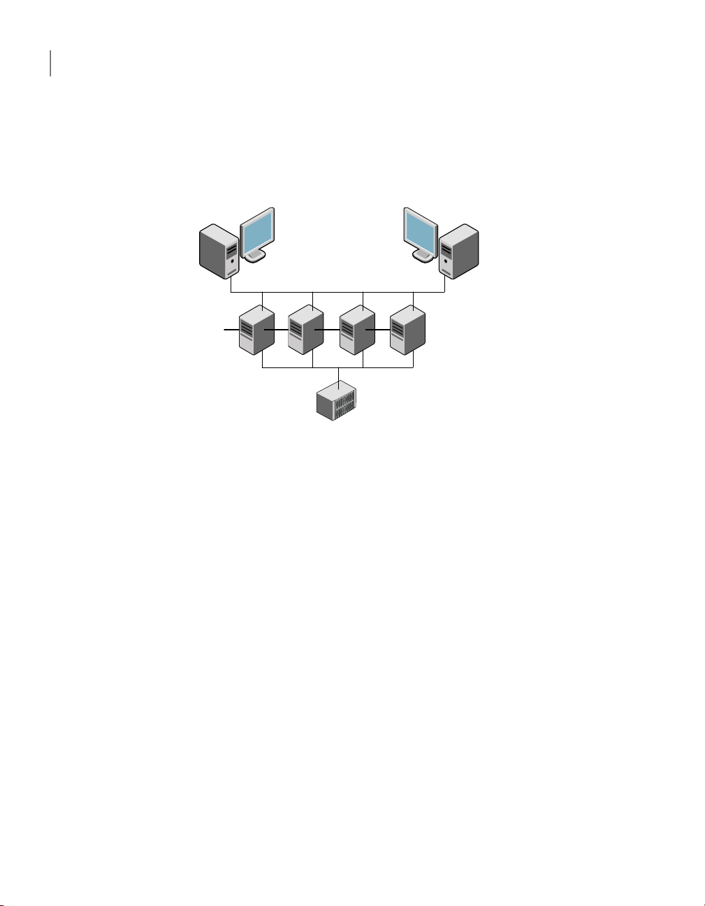
Figure 1-1illustrates a typical VCS configurationof four nodes that are connected
to shared storage.
Figure 1-1
Client workstations receive service over the public network from applications
running on VCS nodes. VCS monitors the nodes and their services. VCS nodes in
the cluster communicate over a private network.
About multiple nodes
VCS runs in a replicated state on each node in the cluster. A private network
enables the nodes to share identical state information about all resources. The
private network also recognizes active nodes, the nodes that join or leave the
cluster, and failed nodes. The private network requires two communication
channels to guard against network partitions.
Example of a four-node VCS cluster
About shared storage
A VCS hardware configuration typically consists of multiple nodes that are
connected to shared storage through I/O channels. Shared storage provides
multiple systems with an access path to the same data. It also enables VCS to
restart applications on alternate nodes when a node fails, which ensures high
availability.
VCS nodes can only access physically-attached storage.
Figure 1-2 illustrates the flexibility of VCS shared storage configurations.
Page 15
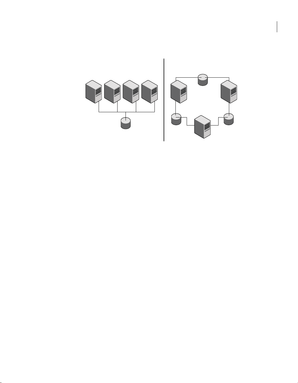
Fully shared storage Distributed shared storage
About VCS basics
15Introducing Veritas Cluster Server
Figure 1-2
About LLT and GAB
VCS uses two components, LLT and GAB, to share data over private networks
among systems. These components provide the performance and reliability that
VCS requires.
LLT (Low Latency Transport) provides fast, kernel-to-kernel communications,
and monitors network connections.
LLT configuration files are as follows:
■ /etc/llthosts—lists all the nodes in the cluster
Two examples of shared storage configurations
■ /etc/llttab file—describes the local system’s private network links to the other
nodes in the cluster
GAB (Group Membership and Atomic Broadcast) provides the global message
order that is required to maintain a synchronized state among the nodes. It
monitors diskcommunications suchas theVCS heartbeat utility. The /etc/gabtab
file is the GAB configuration file.
See “About the LLT and GAB configuration files” on page 105.
About network channels for heartbeating
For the VCS private network, two network channels must be available to carry
heartbeat information.These networkconnections alsotransmit other VCS-related
information.
Each Linux for IBM Power cluster configuration requires at least two network
channels between the systems. The requirement for two channels protects your
cluster against network partitioning. For more information on network
partitioning, refer to the Veritas Cluster Server User's Guide.
Page 16
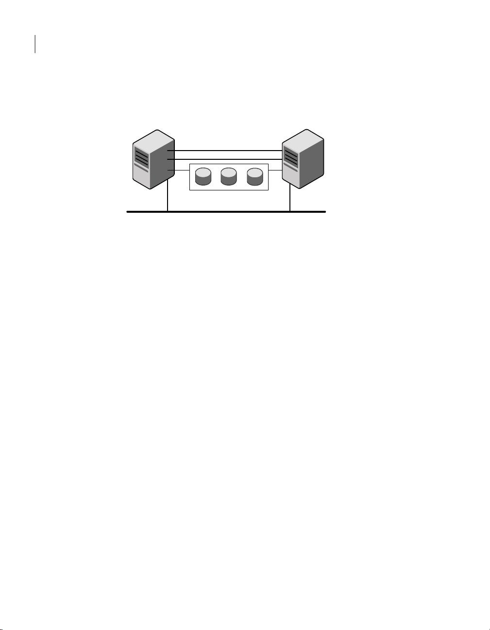
VCS private network: two
ethernet connections
Shared disks
Public network
galaxy nebula
Introducing Veritas Cluster Server
16
About VCS basics
Figure 1-3 illustrates a two-node VCS cluster where the nodes galaxy and nebula
have two private network connections.
Figure 1-3
Two Ethernet connections connecting two nodes
About preexisting network partitions
A preexistingnetwork partition refers to a failure inthe communicationchannels
that occurswhile thesystems aredown andVCS cannot respond. When the systems
start, VCS is vulnerable to network partitioning, regardless of the cause of the
failure.
About VCS seeding
To protect your cluster from a preexisting network partition, VCS uses a seed. A
seed is a function of GAB that determines whether or not all nodes have joined a
cluster. For this determination, GAB requires that you declare the number of
nodes in the cluster. Note that only seeded nodes can run VCS.
GAB automatically seeds nodes under the following conditions:
■ An unseeded node communicates with a seeded node
■ All nodes in the cluster are unseeded but can communicate with each other
When thelast system starts and joins the cluster, the clusterseeds and starts VCS
on all nodes. You can then bring down and restart nodes in any combination.
Seeding remains in effect as long as at least one instance of VCS is running
somewhere in the cluster.
Perform a manual seed to run VCS from a cold start when one or more systems
of the cluster are unavailable. VCS does not start service groupson a systemuntil
it has a seed.
Page 17

About VCS features
You can use the Veritas Installation Assessment Service to assess your setup for
VCS installation.
See “Veritas Installation Assessment Service” on page 17.
VCS offersthe following features that you can configureduring VCSconfiguration:
See “About VCS notifications” on page 17.VCS notifications
See “About global clusters” on page 17.VCS global clusters
See “About I/O fencing” on page 18.I/O fencing
Veritas Installation Assessment Service
The Veritas Installation Assessment Service (VIAS) utility assists you in getting
ready fora Veritas Storage Foundation and High AvailabilitySolutions installation
or upgrade. The VIAS utility allows the preinstallation evaluation of a
configuration, to validate it prior to starting an installation or upgrade.
https://vias.symantec.com/
About VCS features
17Introducing Veritas Cluster Server
About VCS notifications
You can configure both SNMP and SMTP notifications for VCS. Symantec
recommends you to configure one of these notifications. You have the following
options:
■ Configure SNMP trap notification of VCS events using the VCS Notifier
component
■ Configure SMTP email notification of VCS events using the VCS Notifier
component.
See the Veritas Cluster Server User’s Guide.
About global clusters
Global clustersprovide the ability to failover applications between geographically
distributed clusters when disaster occurs. You require a separate license to
configure global clusters. You must add this license during the installation. The
installer only asks about configuring global clusters if you have used the global
cluster license.
See the Veritas Cluster Server User's Guide.
Page 18

Introducing Veritas Cluster Server
18
About VCS optional components
About I/O fencing
I/O fencing protects the data on shared disks when nodes in a cluster detect a
change in the cluster membership that indicates a split brain condition.
See the Veritas Cluster Server User's Guide.
The fencing operation determines the following:
■ The nodes that must retain access to the shared storage
■ The nodes that must be ejected from the cluster
This decision prevents possible data corruption. The installvcs program installs
the VCSI/O fencingdriver, VRTSvxfen. To protect data on shared disks, you must
configure I/O fencing after you install and configure VCS.
I/O fencing technology uses coordination points for arbitration in the event of a
network partition.
Note: Symantec recommends that you use I/O fencing to protect your cluster
against split-brain situations.
About VCS optional components
You can add the following optional components to VCS:
Symantec Product
Authentication Service
Veritas Cluster Server
Management Console
To configure the optional components, make sure to install all RPMs when the
installation program prompts you.
Figure 1-4 illustrates a sample VCS deployment with the optional components
configured.
See “About Symantec Product Authentication Service
(AT)” on page 19.
See “AboutVeritas ClusterServer ManagementConsole”
on page 20.
See “AboutCluster Manager (JavaConsole)” on page20.Cluster Manager (Java console)
See “About VCS Simulator” on page 20.VCS Simulator
Page 19
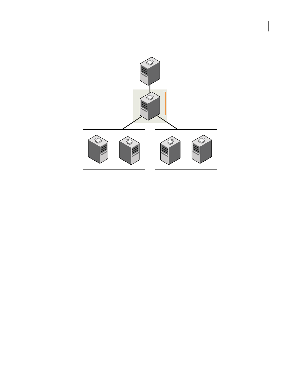
Symantec Product
Authentication Service
root broker
VCS cluster 1 VCS cluster 2
VCS Management Console
management server
Optional
About VCS optional components
19Introducing Veritas Cluster Server
About Symantec Product Authentication Service (AT)
Figure 1-4
Typical VCS setup with optional components
VCS uses Symantec Product Authentication Service (AT) to provide secure
communication between cluster nodes and clients. It uses digital certificates for
authentication and SSL to encrypt communication over the public network to
secure communications.
AT uses the following brokers to establish trust relationship between the cluster
components:
■ Root broker
A root broker serves as the main registration and certification authority; it
has a self-signed certificate and can authenticate other brokers. The root
broker is only used during initial creation of an authentication broker.
A root broker can serve multiple clusters. Symantec recommends that you
install a single root broker on a utility system. The utility system, such as an
email server or domain controller, can be highly available.
■ Authentication brokers
Authentication brokers serve as intermediate registration and certification
authorities. Authentication brokers have root-signed certificates. Each node
in VCS serves as an authentication broker.
See Symantec Product Authentication Service documentation for more
information.
Page 20

Introducing Veritas Cluster Server
20
About VCS optional components
See “Preparing to configure the clusters in secure mode” on page 29.
About Cluster Manager (Java Console)
Cluster Manager (Java Console) offers complete administration capabilities for
your cluster. Use the different views in the Java Console to monitor clusters and
VCS objects, including service groups, systems, resources, and resource types.
You canperform manyadministrative operations using the Java Console. You can
also perform these operations using the command line interface or using the
Veritas Cluster Server Management Console.
See “Installing the Java Console” on page 80.
See Veritas Cluster Server User's Guide.
About Veritas Cluster Server Management Console
Veritas Cluster Server Management Console is a high availability management
solution that enables monitoring and administering clusters from a single Web
console.
You canconfigure VeritasCluster Server Management Console to manage multiple
clusters.
Refer to the Veritas Cluster Server Management Console Implementation Guide
for installation, upgrade, and configuration instructions.
For information on updates and patches for VCS Management Console, see
http://seer.entsupport.symantec.com/docs/308405.htm.
To download the most current version of VCS Management Console, go to
www.symantec.com/business/cluster-server and click Utilities.
About VCS Simulator
VCS Simulator enables you to simulate and test cluster configurations. Use VCS
Simulator to view and modify service group and resource configurations and test
failover behavior. VCS Simulator can be run on a stand-alone system and does
not require any additional hardware.
VCS Simulator runs an identical version of the VCS High Availability Daemon
(HAD) as in a cluster, ensuring that failover decisions are identical to those in an
actual cluster.
You cantest configurationsfrom different operating systems using VCS Simulator.
For example, you can run VCS Simulator on a Windows system and test VCS
Page 21

About VCS optional components
configurations for Windows, Linux, and Solaris clusters. VCS Simulator also
enables creating and testing global clusters.
You can administer VCS Simulator from the Java Console or from the command
line.
21Introducing Veritas Cluster Server
Page 22

Introducing Veritas Cluster Server
22
About VCS optional components
Page 23

Chapter
Planning to install VCS
This chapter includes the following topics:
■ About planning to install VCS
■ Hardware requirements
■ Supported operating systems
■ Supported software
About planning to install VCS
2
Every node where you want to install VCS must meet the hardware and software
requirements.
For the latest information on updates, patches, and software issues, read the
following Veritas Technical Support TechNote:
http://entsupport.symantec.com/docs/285834
To find information on supported hardware, see the hardware compatibility list
(HCL) in the following TechNote:
http://entsupport.symantec.com/docs/286819
Hardware requirements
Table 2-1 lists the hardware requirements for a VCS cluster.
Page 24

Planning to install VCS
24
Hardware requirements
Table 2-1
VCS nodes
DVD drive
Disks
Disk space
Network Interface
Cards (NICs)
Fibre Channel or
SCSI host bus
adapters
Hardware requirements for a VCS cluster
DescriptionItem
From 1 to 32 Linux PPC systems running the supported Linux PPC
operating system version.
One drive in a system that can communicate to all the nodes in the
cluster.
Typical VCS configurations require that shared disks support the
applications that migrate between systems in the cluster.
The VCS I/O fencing feature requires that all data and coordinator
disks support SCSI-3 Persistent Reservations (PR).
See “About setting up disk-based I/O fencing” on page 89.
Note: VCSmay requiremore temporarydisk spaceduring installation
than the specified disk space.
In addition to the built-in public NIC, VCS requires at least one more
NIC per system. Symantec recommends two additional NICs.
You can also configure aggregated interfaces.
Typical VCSconfiguration requiresat leastone SCSIor FibreChannel
Host Bus Adapter per system for shared data disks.
Required disk space
Confirm that your system has enough free disk space to install VCS.
Table 2-2 shows the approximate disk space usage by directory for the Veritas
Cluster Server RPMs.
Table 2-2
optional total
Each VCS node requires at least 256 megabytes.RAM
Disk space requirements and totals
Totals/var/usr/opt/Packages
283 MB1 MB8 MB271 MB3 MBRequired
60 MB7 MB0 MB52 MB1 MBOptional
343 MB8 MB8 MB323 MB4 MBRequired and
Page 25

Note: If you do not have enough free space in /var, then use the installvcs
command with tmppath option. Make sure that the specified tmppath file system
has the required free space.
Supported operating systems
VCS operates on the Linux operating systems and kernels distributed by Red Hat
and SUSE.
Table 2-3 lists the supported operating system versions for Red Hat Enterprise
Linux (RHEL) and SUSE Linux Enterprise Server (SLES). The table also lists the
supported kernel versions and the architecture.
Supported operating systems
25Planning to install VCS
Table 2-3
Supported Linux operating system and kernel versions
ArchitectureKernelOperating System
ppc642.6.18-53.el5RHEL 5 Update 1
ppc642.6.18-92.el5RHEL 5 Update 2
SLES 10 with SP1
2.6.16.46-0.12-smp
SLES 10 with SP2
2.6.16.60-0.21-smp
ppc642.6.16.46-0.12-default
ppc642.6.16.60-0.21-default
Note: If your system runs an older version of either Red Hat Enterprise Linux or
SUSE Linux Enterprise Server, you must upgrade the operating system before
you attempt to install the VCS software. Refer to the Red Hat or SUSE
documentation for more information on upgrading your system.
Symantec supports only Red Hat and SUSE distributed kernel binaries.
Symantec products operate on subsequent kernel and patch releases provided
the operating systems maintain kernel ABI (application binary interface)
compatibility.
Information about the latest supported Red Hat erratas and updates and SUSE
service packs is available in the following TechNote. The TechNote also includes
any updatesto the supported operating systems and software. Read thisTechNote
before you install Symantec products.
http://entsupport.symantec.com/docs/285834
Page 26

Planning to install VCS
26
Supported operating systems
Required Linux RPMs for VCS
Make sure you installed the following operating system-specific RPMs on the
systems where you want to install or upgrade VCS. VCS will support any updates
made to the following RPMs, provided the RPMs maintain the ABI compatibility.
Table 2-4 lists the RPMs that VCS requires for a given Linux operating system.
Table 2-4
RHEL 5
SLES 10
Required RPMs
Required RPMsOperating system
glibc-2.5-34.ppc.rpm
glibc-2.5-34.ppc64.rpm
glibc-common-2.5-34.ppc.rpm
libgcc-4.1.2-44.el5.ppc.rpm
libgcc-4.1.2-44.el5.ppc64.rpm
compat-libgcc-296-2.96-138.ppc.rpm
libstdc++-4.1.2-44.el5.ppc.rpm
libstdc++-4.1.2-44.el5.ppc64.rpm
compat-libstdc++-296-2.96-138.ppc.rpm
compat-libstdc++-33-3.2.3-61.ppc.rpm
compat-libstdc++-33-3.2.3-61.ppc64.rpm
java-1.4.2-gcj-compat-1.4.2.0-40jpp.115.ppc.rpm
glibc-2.4-31.54.ppc.rpm
glibc-64bit-2.4-31.54.ppc.rpm
compat-libstdc++-64bit-5.0.7-22.2.ppc.rpm
compat-libstdc++-5.0.7-22.2.ppc.rpm
compat-2006.1.25-11.2.ppc.rpm
libgcc-4.1.2_20070115-0.21.ppc.rpm
libgcc-64bit-4.1.2_20070115-0.21.ppc.rpm
libstdc++-4.1.2_20070115-0.21.ppc.rpm
libstdc++-64bit-4.1.2_20070115-0.21.ppc.rpm
Page 27

Supported software
Veritas Cluster Server supports the previous and next versions of Storage
Foundation to facilitate product upgrades, when available.
VCS supports the following volume managers and files systems:
■ ext2, ext3, reiserfs, NFS, NFSv4, and bind on LVM2, Veritas Volume Manager
(VxVM) 5.0, and raw disks.
■ Veritas Volume Manager (VxVM) with Veritas File System (VxFS)
■ VxVM
VRTSvxvm-common-5.0.33.00-RU3_SLES10
VRTSvxvm-platform-5.0.33.00-RU3_SLES10
VRTSvxvm-common-5.0.33.00-RU3_RHEL5
VRTSvxvm-platform-5.0.33.00-RU3_RHEL5
■ VxFS
VRTSvxfs-common-5.0.33.00-RU3_SLES10
VRTSvxfs-platform-5.0.33.00-RU3_SLES10
VRTSvxfs-common-5.0.33.00-RU3_RHEL5
VRTSvxfs-platform-5.0.33.00-RU3_RHEL5
Supported software
27Planning to install VCS
Page 28

Planning to install VCS
28
Supported software
Page 29

Chapter
Preparing to install VCS
This chapter includes the following topics:
■ About preparing to install VCS
■ Preparing to configure the clusters in secure mode
■ Performing preinstallation tasks
About preparing to install VCS
Before you perform the preinstallation tasks, make sure you reviewed the
installation requirements,set up the basic hardware, and plannedyour VCS setup.
3
Preparing to configure the clusters in secure mode
You can set up Symantec Product Authentication Service (AT) for the cluster
during the VCS installation or after the installation.
If you want to enable AT in a cluster at a later time, refer to the Veritas Cluster
Server User's Guide for instructions.
The prerequisites to configure a cluster in secure mode are as follows:
■ A system in your enterprise is configured as root broker (RB).
If a root broker system does not exist, install and configure root broker on a
system.
See “Installing the root broker for the security infrastructure” on page 33.
■ An authentication broker (AB) account for each node in the cluster is set up
on the root broker system.
See “Creating authentication broker accounts on root broker system”
on page 34.
Page 30

Preparing to install VCS
30
Preparing to configure the clusters in secure mode
■ The system clocks of the root broker and authentication brokers must be in
sync.
The installvcs program provides the following configuration modes:
Automatic mode
Semi-automatic
mode
Manual mode
The root broker system must allow rsh or ssh passwordless login to
use this mode.
This mode requires encrypted files (BLOB files) from the AT
administrator to configure a cluster in secure mode.
The nodes in the cluster must allow rsh or ssh passwordless login.
See “Setting up inter-system communication” on page 44.
This mode requires root_hash file and the root broker information
from the AT administrator to configure a cluster in secure mode.
The nodes in the cluster must allow rsh or ssh passwordless login.
See “Setting up inter-system communication” on page 44.
Figure 3-1 depicts the flow of configuring VCS cluster in secure mode.
Page 31

Configure the cluster in secure mode
Review AT concepts and gather required information
Install root broker on a stable system
Select a mode to
configure the
cluster in secure
mode
Does the root
broker allow you
to login without
password
Automatic mode
On the root broker system,
create encrypted file (BLOB) for
each node
Copy encrypted files to the
installation system
Set up passwordless
communication between nodes
No action required
Copy root_hash file from the
root broker system to the
installation system
Gather information to answer
prompts
Set up passwordless
communication between nodes
Manual mode
Semiautomatic
mode
Enable LDAP authentication plugin if VCS users belong
to LDAP domain
On the root broker system, create authentication broker
identities for each node
No No
Yes
Automatic mode
Preparing to configure the clusters in secure mode
31Preparing to install VCS
Figure 3-1
Workflow to configure VCS cluster in secure mode
Table 3-1 lists the preparatory tasks in the order which the AT and VCS
administrators must perform.
Page 32

Preparing to install VCS
32
Preparing to configure the clusters in secure mode
Table 3-1
Preparatory tasks to configure a cluster in secure mode
Tasks
secure mode:
■ Automatic mode
■ Semi-automatic mode
■ Manual mode
See “Installing the root broker for the security infrastructure”
on page 33.
each node in the cluster.
See “Creating authentication broker accountson root broker system”
on page 34.
AT administrator requires the following information from the VCS
administrator:
■ Node namesthat aredesignated toserve as authentication brokers
■ Password for each authentication broker
files) for each node and provide the files to the VCS administrator.
See “Creating encrypted files for the security infrastructure”
on page 35.
AT administrator requires the following additional information from
the VCS administrator:
■ Administrator password for each authentication broker
Typically, the password is the same for all nodes.
Who performs
this task
VCS administratorDecide one of the followingconfiguration modes to set up a cluster in
AT administratorInstall the root broker on a stable system in the enterprise.
AT administratorOn the root broker system, create authentication broker accounts for
AT administratorTo use the semi-automatic mode, create the encrypted files (BLOB
(/opt/VRTSat/bin/root_hash) from the root brokersystem to the VCS
administrator.
to the system from where you plan to install and configure VCS.
See “Preparingthe installation system for the security infrastructure”
on page 37.
AT administratorTo use the manual mode, provide the root_hash file
VCS administratorCopy the files that are required to configure a cluster in secure mode
Page 33

Preparing to configure the clusters in secure mode
Installing the root broker for the security infrastructure
Install the root broker only if you plan to useAT to configure the cluster in secure
mode. The root broker administrator must install and configure the root broker
before you configure the Authentication Service for VCS. Symantec recommends
that you install the root broker on a stable system that is outside the cluster.
You can install the root broker on an AIX, HP-UX, Linux, or Solaris system.
See Symantec Product Authentication Service documentation for more
information.
See “About Symantec Product Authentication Service (AT)” on page 19.
To install the root broker
Change to the directory where you can start the Veritas product installer:
1
# ./installer
From the opening Selection Menu, choose: I for "Install/Upgrade a Product."
2
From the displayed list of products to install, choose: Symantec Product
3
Authentication Service.
To install the root broker, select the mode of AT installation as root mode
4
from the three choices that the installer presents:
33Preparing to install VCS
1)Root+AB Mode
2)Root Mode
3)AB Mode
Enter the mode which you would like AT installed? [1-3,q] 2
Enter the name of the system where you want to install the root broker.
5
Enter the system name on which to install AT: venus
Review the output as the installer does the following:
6
■ Checks to make sure that VCS supports the operating system
■ Checks if the system is already configured for security
Review theoutput as the installer checks for theinstalled RPMson the system.
7
The installerlists the RPMs that theprogram is about to install on thesystem.
Press Enter to continue.
Review the output as the installer installs the root broker on the system.
8
Page 34

Preparing to install VCS
34
Preparing to configure the clusters in secure mode
Enter y when the installer prompts you to configure the Symantec Product
9
Authentication Service.
Press the Enter key to start the Authentication Server processes.
10
Do you want to start Symantec Product Authentication Service
processes now? [y,n,q] y
Enter an encryption key. Make sure that you enter a minimum of five
11
characters.
You must use this encrypted key with the -enckeyfile option when you use
the -responsefile option for installation.
Press Enter to continue and review the output as the installer displays the
12
location of the installation log files, summary file, and the response file.
Creating authentication broker accounts on root broker system
On theroot broker system, the administrator must create an authenticationbroker
(AB) account for each node in the cluster.
To create authentication broker accounts on root broker system
Determine the root broker domain name. Enter the following command on
1
the root broker system:
venus> # vssat showalltrustedcreds
For example, the domain name resembles "Domain Name:
root@venus.symantecexample.com" in the output.
For each node in the cluster, verify whether an account exists on the root
2
broker system.
For example, to verify that an account exists for node galaxy:
venus> # vssat showprpl --pdrtype root \
--domain root@venus.symantecexample.com --prplname galaxy
■ If the output displays the principal account on root broker for the
authentication broker on the node, then delete the existing principal
accounts. For example:
venus> # vssat deleteprpl --pdrtype root \
--domain root@venus.symantecexample.com \
--prplname galaxy --silent
Page 35

Preparing to configure the clusters in secure mode
■ If the output displays the following error, then the account for the given
authentication broker is not created on this root broker:
"Failed To Get Attributes For Principal"
Proceed to step 3.
Create a principal account for each authentication broker in the cluster. For
3
example:
venus> # vssat addprpl --pdrtype root --domain \
root@venus.symantecexample.com --prplname galaxy \
--password password --prpltype service
You mustuse thispassword that you create in the input file for the encrypted
file.
Creating encrypted files for the security infrastructure
Create encrypted files (BLOB files) only if you plan to choose the semiautomatic
mode that uses an encrypted file to configure the Authentication Service. The
administrator must create the encrypted files on the root broker node. The
administrator must create encrypted files for each node that is going to be a part
of the cluster before you configure the Authentication Service for VCS.
To create encrypted files
35Preparing to install VCS
Make a note of the following root broker information. This information is
1
required for the input file for the encrypted file:
hash
root_domain
Make anote of the following authentication broker informationfor eachnode.
2
The value of the root hash string, which consists of 40
characters. Execute the following command to find
this value:
venus> # vssat showbrokerhash
The value for the domain name of the root broker
system. Execute the following command to find this
value:
venus> # vssat showalltrustedcreds
This information is required for the input file for the encrypted file:
Page 36

Preparing to install VCS
36
Preparing to configure the clusters in secure mode
identity
password
broker_admin_password
For each node in the cluster, create the input file for the encrypted file.
3
The valuefor theauthentication brokeridentity, which
you providedto createauthentication broker principal
on the root broker system.
This is the value for the --prplname option of the
addprpl command.
See “Creating authentication broker accounts on root
broker system” on page 34.
The value for the authentication broker password,
which you provided to create authentication broker
principal on the root broker system.
This is the value for the --password option of the
addprpl command.
See “Creating authentication broker accounts on root
broker system” on page 34.
The value for the authentication broker password for
Administrator account on the node. This password
must be at least five characters.
The installer presents the formatof the input file for the encrypted filewhen
you proceed to configure the Authentication Service using encrypted file.
For example, the input file for authentication broker on galaxy resembles:
[setuptrust]
broker=venus.symantecexample.com
hash=758a33dbd6fae751630058ace3dedb54e562fe98
securitylevel=high
[configab]
identity=galaxy
password=password
root_domain=vx:root@venus.symantecexample.com
root_broker=venus.symantecexample.com:2821
broker_admin_password=ab_admin_password
start_broker=false
enable_pbx=false
Back up these input files that you created for the authentication broker on
4
each node in the cluster.
Page 37

Preparing to configure the clusters in secure mode
Note that for security purposes, the command to create the output file for
the encrypted file deletes the input file.
For each node in thecluster, create the output file for the encryptedfile from
5
the root broker system using the following command.
RootBroker> # vssat createpkg \
--in /path/to/blob/input/file.txt \
--out /path/to/encrypted/blob/file.txt \
--host_ctx AB-hostname
For example:
venus> # vssat createpkg --in /tmp/galaxy.blob.in \
--out /tmp/galaxy.blob.out --host_ctx galaxy
Note that this command creates an encrypted file even if you provide wrong
password for "password=" entry. But such an encrypted file with wrong
password fails to install on authentication broker node.
After you complete creating the output files for the encrypted file, you must
6
copy these files to the installer node.
37Preparing to install VCS
Preparing the installation system for the security infrastructure
The VCS administrator must gather the required information and prepare the
installation system to configure a cluster in secure mode.
To prepare the installation system for the security infrastructure
Depending on the configuration mode you decided to use, do one of the
◆
following:
Automatic mode
Semi-automatic
mode
Do the following:
■ Gather the root broker system name from the AT
administrator.
■ During VCS configuration, choose the configuration option
1 when the installvcs program prompts.
Do the following:
■ Copy theencrypted files(BLOB files)to thesystem fromwhere
you plan to install VCS.
Note the path of these files that you copiedto theinstallation
system.
■ During VCS configuration, choose the configuration option
2 when the installvcs program prompts.
Page 38

Preparing to install VCS
38
Performing preinstallation tasks
Manual mode
Do the following:
■ Copy the root_hash file that you fetched to the system from
where you plan to install VCS.
Note the path of the root hash file that you copied to the
installation system.
■ Gather the root broker information such as name, fully
qualified domain name, domain, and port from the AT
administrator.
■ Note the principal name and password information for each
authentication broker that you provided to the AT
administrator to create the authentication broker accounts.
■ During VCS configuration, choose the configuration option
3 when the installvcs program prompts.
Performing preinstallation tasks
Table 3-2 lists the tasks you must perform before proceeding to install VCS.
Table 3-2
network.
Preinstallation tasks
ReferenceTask
See “Obtaining VCS license keys” on page 39.Obtain license keys.
See “Setting up the private network” on page 40.Set up the private
interfaces
between systems.
systems.
I/O fencing (optional)
Set the PATH and the
MANPATH variables.
tunable
See “Configuring SuSE network interfaces” on page 42.Configure SuSE network
See “Setting up inter-system communication” on page 44.Enable communication
See “Setting up ssh on cluster systems” on page 45.Set up ssh on cluster
See “Setting up shared storage” on page 46.Set upshared storagefor
See “Setting the PATH variable” on page 47.
See “Setting the MANPATH variable” on page 47.
See “Setting the kernel.panic tunable” on page 48.Set the kerne.panic
Page 39

Performing preinstallation tasks
39Preparing to install VCS
Table 3-2
Review basic
instructions to optimize
LLT media speeds.
Review guidelinesto help
you set the LLT
interconnects.
before installation
Obtaining VCS license keys
This productincludes a License Key certificate. The certificatespecifies the product
keys and the number of product licenses purchased. A single key lets you install
the product on the number and type of systems for which you purchased the
license. A key may enable the operation of more products than are specified on
the certificate.However, you are legally limited to thenumber ofproduct licenses
purchased. The product installation procedure describes how to activate the key.
To registerand receive a software licensekey, goto the Symantec Licensing Portal
at the following location:
https://licensing.symantec.com
Make sure you have your Software Product License document. You need
information in this document to retrieve and manage license keys for your
Symantec product. After you receive the license key, you can install the product.
Click the Help link at this site to access the License Portal User Guide and FAQ.
The VRTSvlic package enables product licensing. After the VRTSvlic is installed,
the following commands and their manual pages are available on the system:
Preinstallation tasks (continued)
ReferenceTask
See “Optimizing LLT media speed settings on private NICs”
on page 48.
See “Guidelines for setting the media speed of the LLT
interconnects” on page 48.
See “Mounting the product disc” on page 49.Mount the product disc
See “Performing automated pre-installation check” onpage 49.Verify the systems
vxlictest
Installs a license key for a Symantec productvxlicinst
Displays currently installed licensesvxlicrep
Retrieves the features and their descriptions that are encoded in a
license key
Page 40

Public network Public network
Private
network
Private network switches or hubs
Preparing to install VCS
40
Performing preinstallation tasks
You canonly installthe Symantec software products for which you have purchased
a license.The enclosedsoftware discsmight includeother products for which you
have not purchased a license.
Setting up the private network
VCS requires you to set up a private network between the systems that form a
cluster. Youcan use either NICs oraggregated interfacesto set up private network.
You can use network switches instead of hubs.
Refer to the Veritas Cluster Server Administrator's Guide to review VCS
performance considerations.
Figure 3-2 shows two private networks for use with VCS.
Figure 3-2
Symantec recommendsconfiguring twoindependent networksbetween thecluster
nodes with a network switch for each network. You can also connect the two
switches at layer 2 for advanced failure protection. Such connections for LLT at
layer 2 are called cross-links.
Figure 3-3 shows a private network configuration with crossed links between the
network switches.
Private network setups: two-node and four-node clusters
Page 41

Crossed link
Public network
Private networks
Performing preinstallation tasks
41Preparing to install VCS
Figure 3-3
Private network setup with crossed links
To set up the private network
Install the required network interface cards (NICs).
1
Create aggregatedinterfaces if you want to use theseto setup private network.
Connect the VCS private NICs on each system.
2
Use crossover Ethernet cables, switches, or independent hubs for each VCS
3
communication network. Note that the crossover Ethernet cables are
supported only on two systems.
Ensure that you meet the following requirements:
■ The power to the switches or hubs must come from separate sources.
■ On each system, you must use two independent network cards to provide
redundancy.
■ The network interface card to set up private interface is not part of any
aggregated interface.
During theprocess of setting up heartbeat connections, considera case where
a failure removes all communications between the systems.
Note that a chance for data corruption exists under the following conditions:
■ The systems still run, and
Page 42

Preparing to install VCS
42
Performing preinstallation tasks
■ The systems can access the shared storage.
Test the network connections. Temporarily assign network addresses and
4
use telnet or ping to verify communications.
LLT uses its own protocol, and does not use TCP/IP. So, youmust ensure that
the private network connections are used only for LLT communication and
not for TCP/IP traffic. To verify this requirement, unplumb and unconfigure
any temporary IP addresses that are configured on the network interfaces.
The installvcs program configures the private network in the cluster during
installation.
See “About installing and configuring VCS” on page 51.
Configuring SuSE network interfaces
You mustperform additionalnetwork configurationon SuSE.You neednot perform
this procedure for the systems that run SLES 10 or later. By default, SLES 10 uses
udev to achieve persistent interface names. Refer to the OS documentation for
information on configuring persistent interfaces on SLES 10.
In rare cases where RedHat does not automatically configure the network
interfaces, RedHat users may also have to perform the network configuration.
Review the following tasks that allow VCS to function properly:
■ VCS must be able to find the same network interface names across reboots.
■ VCS must have network interfaces up before LLT starts to run.
Symantec suggests the following steps for configuring network interfaces on
SUSE.
Note: You must not reboot the system between configuringthe persistentinterface
names and configuring the interfaces to be up before starting LLT.
Note: The MAC address in the ifcfg-eth-id-mac file can be in uppercase or
lowercase. SUSE,and therefore the Veritas product installer, ignoresthe filewith
lowercase MAC address if the file with uppercase MAC address is present.
Page 43

Performing preinstallation tasks
To configure persistent interface names for network devices
Navigate to the hotplug file in the /etc/sysconfig directory:
1
# cd /etc/sysconfig
Open the hotplug file in an editor.
2
Set HOTPLUG_PCI_QUEUE_NIC_EVENTS to yes:
3
HOTPLUG_PCI_QUEUE_NIC_EVENTS=yes
Run the command:
4
ifconfig -a
Make sure that the interface name to MAC address mapping remains same
5
across the reboots.
Symantec recommends adding the PERSISTENT_NAME entries to the
configuration files for all the network interfaces (including the network
interfaces that are not used).
For each ethernet interface displayed, do the following:
■ If afile named /etc/sysconfig/network/ifcfg-eth-id-mac, where mac is the
hardware address of that interface, does not exist, then do the following:
Create the file.
If a file exists for the same network interface with the name
/etc/sysconfig/network/ifcfg-ethX, thencopy the contents of thatfile into
the newly created file. The variable ethX represents the interface name.
■ Add the following line at the end of the file
/etc/sysconfig/network/ifcfg-eth-id-mac.
43Preparing to install VCS
PERSISTENT_NAME=ethX
where ethX is the interface name.
For example:
# ifconfig -a
eth0 Link encap:Ethernet HWaddr 00:02:B3:DB:38:FE
inet addr:10.212.99.30 Bcast:10.212.99.255
Mask:255.255.254.0
inet6 addr: fe80::202:b3ff:fedb:38fe/64 Scope:Link
UP BROADCAST RUNNING MULTICAST MTU:1500 Metric:1
RX packets:453500 errors:0 dropped:0 overruns:0 frame:0
TX packets:8131 errors:0 dropped:0 overruns:0 carrier:0
Page 44

Preparing to install VCS
44
Performing preinstallation tasks
collisions:0 txqueuelen:1000
RX bytes:35401016 (33.7 Mb) TX bytes:999899 (976.4 Kb)
Base address:0xdce0 Memory:fcf20000-fcf40000
If a file named etc/sysconfig/network/ifcfg-eth-id-00:02:B3:DB:38:FE does
not exist, do the following task:
■ Create the file.
■ If thefile /etc/sysconfig/network/ifcfg-eth0 exists, then copythe contents
of this file into etc/sysconfig/network/ifcfg-eth-id-00:02:B3:DB:38:FE.
Add the following to the end of the file named
etc/sysconfig/network/ifcfg-eth-id-00:02:B3:DB:38:FE,
PERSISTENT_NAME=eth0
Perform the procedure for all the interfaces that the ifconfig -a command
displays.
To configure interfaces to be up before starting LLT
For each network interface that you want LLT to use, find its MAC address
1
by running the ifconfig command:
# ifconfig eth0
eth0 Link encap:Ethernet HWaddr 00:0C:0D:08:C4:32
Where eth0 is the sample network interface name. The output displays
00:0C:0D:08:C4:32 as the interface’s MAC address.
Navigate to the config file in the /etc/sysconfig/network directory:
2
# cd /etc/sysconfig/network
Open the config file in an editor.
3
Append the string eth-id-macaddress to the MANDATORY_DEVICES list in
4
the config file. Separate each address with a space, for example:
MANDATORY_DEVICES="eth-id-00:0C:0D:08:C4:31
eth-id-00:0C:0D:08:C4:32"
Setting up inter-system communication
When you install VCS using the installvcs program, to install and configure the
entire clusterat one time, make sure that communicationbetween systems exists.
By default the installer uses ssh. You must grant root privileges for the system
Page 45

Performing preinstallation tasks
where you run installvcs program. This privilege facilitates to issue ssh or rsh
commands on all systems in the cluster. If ssh is used to communicate between
systems, it must be configured in a way suchthat it operates without requests for
passwords or passphrases. Similarly, rsh must be configured in such a way to not
prompt for passwords.
If system communication is not possible between systems using ssh or rsh, you
have recourse.
Warning: The rsh and ssh commands to the remote systems, where VCS is to be
installed, must not print any extraneous characters.
Setting up ssh on cluster systems
Use the Secure Shell (ssh) to install VCS on all systems in a cluster from a system
outside of the cluster. Before you start the installation process, verify that ssh is
configured correctly.
Use Secure Shell (ssh) to do the following:
■ Log on to another system over a network
■ Execute commands on a remote system
45Preparing to install VCS
■ Copy files from one system to another
The ssh shell provides strong authentication and secure communications over
channels. It is intended to replace rlogin, rsh, and rcp.
The Remote Shell (rsh) is disabled by default to provide better security. Use ssh
for remote command execution.
Configuring ssh
The procedureto configuressh uses OpenSSH example file names and commands.
Note: You can configure ssh in other ways. Regardless of how ssh is configured,
complete the last step in the example to verify the configuration.
To configure ssh
Log on to the system from which you want to install VCS.
1
Generate a DSA key pair on this system by running the following command:
2
# ssh-keygen -t dsa
Accept the default location of ~/.ssh/id_dsa.
3
Page 46

Preparing to install VCS
46
Performing preinstallation tasks
When the command prompts, enter a passphrase and confirm it.
4
Change the permissions of the .ssh directory by typing:
5
# chmod 755 ~/.ssh
The file ~/.ssh/id_dsa.pub contains a line that begins with ssh_dss and ends
6
with the name of the system on which it was created. Copy this line to the
/root/.ssh/authorized_keys2 fileon all systems where youplan toinstall VCS.
If the local system is part of the cluster, make sure to edit the
authorized_keys2 file on that system.
Run the following commands on the system where you are installing:
7
# exec /usr/bin/ssh-agent $SHELL
# ssh-add
This step is shell-specific and is valid for the duration the shell is alive.
When the command prompts, enter your DSA passphrase.
8
You are ready to install VCS on several systems in one of the following ways:
■ Run the installvcs program on any one of the systems
■ Run the installvcs program on an independent system outside the cluster
To avoid running the ssh-agent on each shell, run the X-Window system and
configure it so that you are not prompted for the passphrase. Refer to the
Red Hat documentation for more information.
To verify that you can connect to the systems where you plan to install VCS,
9
type:
# ssh -x -l root north ls
# ssh -x -l root south ifconfig
# ssh-copy-id -i ~/.ssh/id_dsa.pub root@north
The commandsshould executeon theremote systemwithout havingto enter
a passphrase or password.
Setting up shared storage
For VCS I/O fencing, the data disks must support SCSI-3 persistent reservations.
You needto configure a coordinator disk group thatsupports SCSI-3 PR and verify
that it works.
See “About setting up disk-based I/O fencing” on page 89.
Page 47

See also the Veritas Cluster Server User's Guide for a description of I/O fencing.
Setting the PATH variable
Installation commands as well as other commands reside in the /sbin, /usr/sbin,
/opt/VRTS/bin, and /opt/VRTSvcs/bin directories. Add these directories to your
PATH environment variable.
To set the PATH variable
Do one of the following:
◆
■ For the Bourne Shell (sh or ksh), type:
$ PATH=/usr/sbin:/sbin:/opt/VRTS/bin:/opt/VRTSvcs/bin:\
$PATH; export PATH
■ For the C Shell (csh or tcsh), type:
% setenv PATH /usr/sbin:/sbin:/opt/VRTS/bin:\
/opt/VRTSvcs/bin:$PATH
Performing preinstallation tasks
47Preparing to install VCS
Setting the MANPATH variable
Set the MANPATH variable to view the manual pages.
To set the MANPATH variable
Do one of the following:
◆
■ For the Bourne Shell (sh or ksh), type:
$ MANPATH=/usr/share/man:/opt/VRTS/man; export MANPATH
■ For the C Shell (csh or tcsh), type:
% setenv MANPATH /usr/share/man:/opt/VRTS/man
If you use the man command to access manual pages, set LC_ALL to "C" in
your shell for correct page display.
# export LC_ALL=C
See incident 82099 on the Red Hat support web site for more information.
Page 48

Preparing to install VCS
48
Performing preinstallation tasks
Setting the kernel.panic tunable
By default, the kernel.panic tunable is set to zero. Therefore the kernel does not
reboot automatically if a node panics. To ensure that the node reboots
automatically after it panics, this tunable must be set to a non zero value.
To set the kernel.panic tunable
Set the kernel.panic tunable to a desired value in the /etc/sysctl.conf file.
1
For example, kernel.panic = 10, will assign a value 10 seconds to the
kernel.panic tunable. This step makes the change persistent across reboots.
Run the command:
2
sysctl -w kernel.panic=10
In case of a panic, the node will reboot after 10 seconds.
Optimizing LLT media speed settings on private NICs
For optimal LLT communication among the cluster nodes, the interface cards on
each node must use the same media speed settings. Also, the settings for the
switches or the hubs that are used for the LLT interconnections must match that
of the interface cards. Incorrect settings can cause poor network performance or
even network failure.
Guidelines for setting the media speed of the LLT interconnects
Review the following guidelines for setting the media speed of the LLT
interconnects:
■ Symantec recommends that you manually set the same media speed setting
on each Ethernet card on each node.
■ If you have hubs or switches for LLT interconnects, then set the hub or switch
port to the same setting as used on the cards on each node.
■ If you use directly connected Ethernet links (using crossover cables), set the
media speed to the highest value common to both cards, typically
100_Full_Duplex.
■ Symantec does not recommend using dissimilar network cards for private
links.
Details for setting the media speeds for specific devices are outside of the scope
of this manual. Consult the device’s documentation for more information.
Page 49

Mounting the product disc
You must have superuser (root) privileges to load the VCS software.
To mount the product disc
Log in as superuser on a system where you want to install VCS.
1
The system from which you install VCS need not be part of the cluster. The
systems must be in the same subnet.
Insert the product disc with the VCS software into a drive that is connected
2
to the system.
The disc is automatically mounted.
If the disc does not automatically mount, then enter:
3
# mount -o ro /dev/cdrom /mnt/cdrom
Navigate to the location of the RPMs.
4
Depending on the OS distribution, type the following appropriate command:
Performing preinstallation tasks
49Preparing to install VCS
# cd /mnt/cdrom/rhel5_ppc64/cluster_serverRHEL 5
# cd /mnt/cdrom/sles10_ppc64/cluster_serverSLES 10
Performing automated pre-installation check
Before you begin the installation of VCS software, you can check the readiness of
the systems where you plan to install VCS. The command to start the
pre-installation check is:
installvcs -precheck system1 system2 ...
You can also use the Veritas Installation Assessment Service utility for a detailed
assessment of your setup.
See “Veritas Installation Assessment Service” on page 17.
Page 50

Preparing to install VCS
50
Performing preinstallation tasks
To check the systems
Navigate to the folder that contains the installvcs program.
1
See “Mounting the product disc” on page 49.
Start the pre-installation check:
2
# ./installvcs -precheck galaxy nebula
The program proceeds in a noninteractive mode to examine the systems for
licenses, RPMs, disk space, and system-to-system communications.
Review the output as the program displays the results of the checkand saves
3
the results of the check in a log file.
Page 51

Chapter
Installing and configuring VCS
This chapter includes the following topics:
■ About installing and configuring VCS
■ Getting your VCS installation and configuration information ready
■ About the VCS installation program
■ Installing and configuring VCS 5.0 RU3
4
■ Verifying and updating licenses on the system
■ Accessing the VCS documentation
About installing and configuring VCS
You can install Veritas Cluster Server on clusters of up to 32 systems. You can
install VCS using one of the following:
Use theproduct installerto installmultiple Veritasproducts.Veritas product installer
Use this to install just VCS.installvcs program
The Veritas product installer and the installvcs program use ssh to install by
default. Refer to the Getting Started Guide for more information.
Page 52

Installing and configuring VCS
52
Getting your VCS installation and configuration information ready
Getting your VCS installation and configuration
information ready
The VCS installation and configuration program prompts you for information
about certain VCS components.
When you perform the installation, prepare the following information:
■ To install VCS RPMs you need:
Example: galaxy, nebulaThe systemnames whereyou
plan to install VCS
The required license keys
To decide whether to install:
■ the required VCS RPMs
■ all the VCS RPMs
■ To configure Veritas Cluster Server you need:
A name for the cluster
A unique ID number for the
cluster
Depending on the type of installation, keys include:
■ A valid site license key
■ A valid demo license key
■ A valid license key for VCS global clusters
See “Obtaining VCS license keys” on page 39.
Install only the required RPMs if you do not want to
configure any optional components or features.
The default option is to install all RPMs.
See “Optional VCS RPMs” on page 54.
The cluster name must begin with a letter of the
alphabet. The cluster name can contain only the
characters "a"through "z","A" through"Z", thenumbers
"0" through "9", the hyphen "-", and the underscore "_".
Example: vcs_cluster27
A number in the range of 0-65535. Within the site that
contains the cluster, each cluster must have a unique
ID.
Example: 7
The devicenames ofthe NICs
that theprivate networksuse
among systems
A network interface card that is not part of any
aggregated interface, or an aggregated interface.
Do not use the network interface card that is used for
the public network, which is typically eth0.
Example: eth1, eth2
Page 53

Getting your VCS installation and configuration information ready
■ To configure VCS clusters in secure mode (optional), you need:
53Installing and configuring VCS
For automaticmode (default)
For semiautomatic mode
using encrypted files
For semiautomatic mode
without usingencrypted files
■ The name of the Root Broker system
Example: east
See “AboutSymantec ProductAuthentication Service
(AT)” on page 19.
■ Access to the Root Broker system without use of a
password.
The path for the encrypted files that you get from the
Root Broker administrator.
See “Creating encrypted files for the security
infrastructure” on page 35.
■ The fully-qualified hostname (FQDN) of the Root
Broker . (e.g. east.symantecexample.com)
The given example puts a system in the (DNS)
domain symantecexample.comwith theunqualified
hostname east, which is designated as the Root
Broker.
■ The root broker’s security domain (e.g.
root@east.symantecexample.com)
■ The root broker’s port (e.g. 2821)
■ The path to the local root hash (e.g.
/var/tmp/privatedir/root_hash)
■ The authentication broker’s principal nameon each
cluster node(e.g. galaxy.symantecexample.com
and nebula.symantecexample.com)
■ To add VCS users, which is notrequired if you configure yourcluster in secure
mode, you need:
User names
User passwords
To decide user privileges
■ To configure SMTP email notification (optional), you need:
VCS usernames are restricted to 1024 characters.
Example: smith
VCS passwords are restricted to 255 characters.
Enter the password at the prompt.
Users have three levels of privileges: A=Administrator,
O=Operator, or G=Guest.
Example: A
Page 54

Installing and configuring VCS
54
Getting your VCS installation and configuration information ready
The domain-basedaddress of
the SMTP server
SMTP recipientto benotified
To decide the minimum
severity of events for SMTP
email notification
■ To configure SNMP trap notification (optional), you need:
SNMP trap daemon
SNMP console
To decide the minimum
severity of events for SNMP
trap notification
■ To configure global clusters (optional), you need:
The SMTP server sends notification emails about the
events within the cluster.
Example: smtp.symantecexample.com
Example: john@symantecexample.comThe email address of each
Events have four levels of severity: I=Information,
W=Warning, E=Error, and S=SevereError.
Example: E
The default port number is 162.The port number for the
Example: saturnThe system name for each
Events have four levels of severity: I=Information,
W=Warning, E=Error, and S=SevereError.
Example: E
The name of the public NIC
The virtual IP address of the
NIC
The netmask for the virtual
IP address
Optional VCS RPMs
The optional VCS RPMs include the following packages:
■ VRTScssim — VCS Simulator
■ VRTScscm — Veritas Cluster Server Cluster Manager
You must specify appropriate values for the NIC.
Example: eth0
You must specify appropriate values for the virtual IP
address.
Example: 192.168.1.16
You must specify appropriate values for the netmask.
Example: 255.255.240.0
Page 55

■ VRTSvcsmn — Manual pages for VCS commands
About the VCS installation program
You can access the installvcs program from the command line or through the
Veritas product installer.
The VCS installation program is interactive and manages the following tasks:
■ Licensing VCS
■ Installing VCS RPMs on multiple cluster systems
■ Configuring VCS, by creating several detailed configuration files on each
system
■ Starting VCS processes
You can choose to configure different optional features, such as the following:
■ SNMP and SMTP notification
■ The Symantec Product Authentication Services feature
■ The wide area Global Cluster feature
About the VCS installation program
55Installing and configuring VCS
Review the highlights of the information for which installvcs program prompts
you as you proceed to configure.
See “About preparing to install VCS” on page 29.
The uninstallvcs program, a companion to installvcs program, uninstalls VCS
RPMs.
See “About the uninstallvcs program” on page 153.
Optional features of the installvcs program
Table 4-1 specifies the optional actions that the installvcs program can perform.
Table 4-1
Check the systems to verify that they meet
the requirements to install VCS.
Install VCS RPMs without configuring VCS.
Configure or reconfigure VCS when VCS
RPMs are already installed.
installvcs optional features
ReferenceOptional action
See “Performingautomated pre-installation
check” on page 49.
See “InstallingVCS usinginstallonly option”
on page 59.
See “Configuring VCS using configure
option” on page 59.
Page 56

Installing and configuring VCS
56
About the VCS installation program
Table 4-1
Perform secureinstallations usingthe values
that are stored in a configuration file.
Perform automated installations using the
values that are stored in a configurationfile.
installvcs optional features (continued)
Interacting with the installvcs program
As you run the program, you are prompted to answer yes or no questions. A set
of responses that resemble [y, n, q, ?] (y) typically follow these questions. The
response within parentheses is the default, which you can select by pressing the
Enter key. Enter the ? character to get help to answer the prompt. Enter q to quit
the installation.
Installation of VCS RPMs takes place only after you have confirmed the
information. However, you must remove the partially installed VCS files before
you run the installvcs program again.
See “About the uninstallvcs program” on page 153.
During theinstallation, the installer prompts you to typeinformation. Theinstaller
expects your responses to be within a certain range or in a specific format. The
installer providesexamples. If you are promptedto enter an item from a list, enter
your selection exactly as it is shown in the list.
The installer also prompts you to answer a series of questions that are related to
a configuration activity. For such questions, you can enter the b character to
return to the first prompt in the series. When the installer displays a set of
information itemsyou have entered, you are prompted toconfirm it. If you answer
n, the program lets you reenter all of the information for the set.
You can install the VCS Java Console on a single system, which is not required to
be part of the cluster. Note that the installvcs program does not install the VCS
Java Console.
See “Installing the Java Console” on page 80.
ReferenceOptional action
See “Installing VCS with a response file
where ssh or rsh are disabled” on page 171.
See “Performing automated VCS
installations” on page 164.
About installvcs program command options
In addition to the -precheck, -responsefile, -installonly, and -configure
options, the installvcs program has other useful options.
The installvcs command usage takes the following form:
Page 57

About the VCS installation program
installvcs [ system1 system2... ] [ options ]
Table 4-2 lists the installvcs command options.
57Installing and configuring VCS
Table 4-2
-configure
encryption_key_file
-encrypt password
-hostfile
-installonly
-installpkgs
-keyfile
ssh_key_file
installvcs options
DescriptionOption and Syntax
Configure VCS after using -installonly option to install
VCS.
See “Configuring VCS using configure option” on page 59.
See the -responsefile and the -encrypt options.-enckeyfile
Encrypt password using the encryption key that is provided
with the-enckeyfile option so thatthe encryptedpassword
can be stored in response files.
Specifies thelocation ofa filethat containsthe systemnames
for the installer.
Install product RPMs on systems without configuring VCS.
See “Installing VCS using installonly option” on page 59.
Display VCS packages in correct installation order. Output
can be used to create scripts for command line installs, or for
installations over a network. See the requiredpkgs option.
Specifies a key file for SSH. The option passes -i
ssh_key_file with each SSH invocation.
-license
-logpath log_path
-noextrapkgs
-nolic
Register or update product licenses on the specified systems.
Useful for replacing demo license.
Specifies that log_path, not /opt/VRTS/install/logs, is the
location whereinstallvcs log files, summary file, and response
file are saved.
Specifies that additional product RPMs such as VxVM and
VxFS need not be installed.
Note: VCS product upgrades in the future can be simplified
if you do not install additional product RPMs.
Install product RPMs on systems without licensing or
configuration. License-based features or variants are not
installed when using this option.
Page 58

Installing and configuring VCS
58
About the VCS installation program
Table 4-2
-nooptionalpkgs
-nostart
-pkgpath pkg_path
-precheck
-requiredpkgs
-responsefile
response_file
[-enckeyfile
encryption_key_file]
installvcs options (continued)
DescriptionOption and Syntax
Specifies that the optional product RPMs such as man pages
and documentation need not be installed.
Bypass starting VCS after completing installation and
configuration.
Specifies that pkg_path contains all RPMs that the installvcs
program is about to install on all systems. The pkg_path is
the complete path of a directory, usually NFS mounted.
Verify thatsystems meetthe installationrequirements before
proceeding with VCS installation.
Symantec recommends doing a precheck before installing
VCS.
See “Performing automated pre-installation check”
on page 49.
Displays all required VCS packages in correct installation
order. Optional packages are not listed. Output can be used
to create scripts for command line installs, or forinstallations
over a network. See installpkgs option.
Perform automatedVCS installationusing thesystem andthe
configuration information that is stored in a specified file
instead of prompting for information.
The response_file must be a full path name. If not specified,
the response file is automatically generated as
installerernumber.response where number is random. You
must edit the response file to use it for subsequent
installations. Variablefield definitions are defined within the
file.
The -enckeyfile option and encryption_key_file name are
required withthe -responsefileoption whenthe response
file contains encrypted passwords.
See “Installing VCS with a response file where ssh or rsh are
disabled” on page 171.
See “Performing automated VCS installations” on page 164.
Page 59

About the VCS installation program
59Installing and configuring VCS
Table 4-2
-rsh
-security
-serial
-timeout
-tmppath tmp_path
installvcs options (continued)
DescriptionOption and Syntax
Specifies that rsh and rcp are to be used for communication
between systemsinstead ofssh andscp. Thisoption requires
that systems be preconfigured such that rsh commands
between systems execute without prompting for passwords
or confirmations
Enable or disable Symantec Product Authentication Service
in a VCS cluster that is running. Install and configure Root
Broker for Symantec Product Authentication Service.
See “About Symantec Product Authentication Service (AT)”
on page 19.
Performs the installation, uninstallation, start, and stop
operations on the systems in a serial fashion. By default, the
installer performsthese operations simultaneously on all the
systems.
Specifies the timeout value (in seconds) for each command
that the installer issues during the installation. The default
timeout value is set to 600 seconds.
Specifies thattmp_path is the working directory for installvcs
program. This path is different from the /var/tmp path. This
destination is where initial logging is performed and where
RPMs are copied on remote systems before installation.
-verbose
Displays the details when the installer installs the RPMs. By
default, the installer displays only a progress bar during the
RPMs installation.
Installing VCS using installonly option
In certainsituations, users may choose to install theVCS RPMs on a system before
they are ready for cluster configuration. During such situations, the installvcs
-installonly option can be used. The installation program licenses and installs
VCS RPMs on the systems that you enter without creating any VCS configuration
files.
Configuring VCS using configure option
If you installed VCS and did not choose to configure VCS immediately, use the
installvcs -configure option. You can configure VCS when you are ready for
Page 60

Node: galaxy
Cluster name: vcs_cluster2
Cluster id: 7
VCS private network
Public network
eth1 eth1
eth2eth2
eth0
eth0
Node: nebula
Installing and configuring VCS
60
Installing and configuring VCS 5.0 RU3
cluster configuration. The installvcs program prompts for cluster information,
and creates VCS configuration files without performing installation.
See “Configuring the basic cluster” on page 67.
The -configure option can be used to reconfigure a VCS cluster. VCS must not
be running on systems when this reconfiguration is performed.
If you manually edited the main.cf file, you need to reformat the main.cf file.
Installing and configuring VCS 5.0 RU3
The exampleinstallation demonstrateshow toinstall VCSon twosystems: galaxy
and nebula. The example installation chooses to install all VCS RPMs and
configures alloptional features. For this example, the cluster’sname isvcs_cluster2
and the cluster’s ID is 7.
Figure 4-1 illustrates the systems on which you would install and run VCS.
Overview of tasks
Figure 4-1
Table 4-3 lists the installation and the configuration tasks.
An example of a VCS installation on a two-node cluster
Page 61

Installing and configuring VCS 5.0 RU3
61Installing and configuring VCS
Table 4-3
License andinstall VCS
Configure the cluster
and its features
files
Start VCS and its
components
Installation and configuration tasks
ReferenceTask
■ See “Starting the software installation” on page 61.
■ See “Specifying systems for installation” on page 62.
■ See “Licensing VCS” on page 63.
■ See “Choosing VCS RPMs for installation” on page 64.
■ See “Choosing to install VCS RPMs or configure VCS”
on page 65.
■ See “Installing VCS RPMs” on page 75.
■ See “Starting the software configuration” on page 66.
■ See “Specifying systems for configuration” on page 67.
■ See “Configuring the basic cluster” on page 67.
■ See “Adding VCS users” on page 71. (optional)
■ See “Configuring SMTP email notification” on page 71.
(optional)
■ See “Configuring SNMP trap notification” on page 73.
(optional)
■ See “Configuring global clusters” on page 74. (optional)
See “Creating VCS configuration files” on page 76.Create configuration
■ See “Starting VCS” on page 77.
■ See “Completing the installation” on page 77.
For clustersthat runin
■ See “Aboutenabling LDAPauthentication for clusters that run
secure mode, enable
LDAP authentication
plug-in if VCS users
belong to LDAP
domain.
Perform the
■ See “About configuring VCS clusters for data integrity”
post-installation tasks
■ See “Installing the Java Console” on page 80.
See “Verifying the cluster after installation” on page 84.Verify the cluster
Starting the software installation
You can install VCS using the Veritas product installer or the installvcs program.
in secure mode” on page 78.
on page 87.
Page 62

Installing and configuring VCS
62
Installing and configuring VCS 5.0 RU3
Note: The system from where you install VCS must run thesame Linuxdistribution
as the target systems.
To install VCS using the product installer
1
2
3
4
To install VCS using the installvcs program
1
2
Confirm that you are logged in as the superuser and mounted the product
disc.
Start the installer.
# ./installer
The installerstarts the product installation program with acopyright message
and specifies the directory where the logs are created.
From the opening Selection Menu, choose: I for "Install/Upgrade a Product."
From the displayed list of products to install, choose: Veritas Cluster Server.
Confirm that you are logged in as the superuser and mounted the product
disc.
Navigate to the folder that contains the installvcs program.
# cd /cluster_server
Start the installvcs program.
3
# ./installvcs [-rsh]
The installer begins with a copyright message and specifies the directory
where the logs are created.
Specifying systems for installation
The installerprompts forthe systemnames onwhich youwant toinstall andthen
performs an initial system check.
Page 63

Licensing VCS
Installing and configuring VCS 5.0 RU3
To specify system names for installation
Enter the names of the systems where you want to install VCS.
1
Enter the system names separated by spaces on which to install
VCS: galaxy nebula
For a single node installation, enter one name for the system.
See “Creatinga single-node cluster using the installer program” on page139.
Review the output as the installer verifies the systems you specify.
2
The installer does the following:
■ Checks that the local node running the installer can communicate with
remote nodes
If the installer finds ssh binaries, it confirms thatssh can operate without
requests for passwords or passphrases.
■ Makes sure the systems use the proper operating system
■ Checks whether VCS is installed
63Installing and configuring VCS
The installer checks whether VCS license keys are currently in place on each
system. If license keys are not installed, the installer prompts you for the license
keys.
See “Checking licensing information on the system” on page 84.
To license VCS
Review the output as the utility checks system licensing and installs the
1
licensing RPM.
Enter the license key for Veritas Cluster Server as the installer prompts for
2
each node.
Enter a VCS license key for galaxy: [?] XXXX-XXXX-XXXX-XXXX-XXX
XXXX-XXXX-XXXX-XXXX-XXX successfully registered on galaxy
VCS license registered on galaxy
Page 64

Installing and configuring VCS
64
Installing and configuring VCS 5.0 RU3
3
4
Enter keys for additional product features.
Do you want to enter another license key for galaxy? [y,n,q,?]
(n) y
Enter a VCS license key for galaxy: [?] XXXX-XXXX-XXXX-XXXX-XXX
XXXX-XXXX-XXXX-XXXX-XXX successfully registered on galaxy
Do you want to enter another license key for galaxy? [y,n,q,?]
(n)
Review theoutput as the installer registersthe license key on the other nodes.
Enter keys for additional product features on the other nodes when the
installer prompts you.
XXXX-XXXX-XXXX-XXXX-XXX successfully registered on nebula
VCS license registered on nebula
Do you want to enter another license key for nebula? [y,n,q,?]
(n)
Choosing VCS RPMs for installation
The installer verifies for any previously installed RPMs and then based on your
choice installs all the VCS RPMs or only the required RPMs.
Page 65

Installing and configuring VCS 5.0 RU3
To install VCS RPMs
Review theoutput asthe installerchecks theRPMs thatare alreadyinstalled.
1
Choose the VCS RPMs that you want to install.
2
Select the RPMs to be installed on all systems? [1-3,q,?]
(3) 2
Based on what RPMs you want to install, enter one of the following:
Installs only the required VCS RPMs.1
Installs all the VCS RPMs.
2
You must choose this option to configure any optional VCS feature.
Note that this option is the default if you already installed the SF HA RPMs.
Installs all the VCS and the SF HA RPMs. (default option)
3
If you already installed the SF HA RPMs, theinstaller doesnot listthis option.
View the list of RPMs that the installer would install on each node.
3
If the current version of a RPM is on a system, the installer removes it from
the RPM installation list for the system.
65Installing and configuring VCS
Choosing to install VCS RPMs or configure VCS
While you must configure VCS before you can use VCS, you can do one of the
following:
■ Choose to install and configure VCS now.
See “Configuring the basic cluster” on page 67.
■ Install packages on the systems and leave the cluster configuration steps for
later.
Page 66

Installing and configuring VCS
66
Installing and configuring VCS 5.0 RU3
To install VCS packages now and configure VCS later
If you do not want to configure VCS now, enter n at the prompt.
1
Are you ready to configure VCS? [y,n,q] (y) n
The utility checks for the required file system space and makes sure that any
processes that are running do not conflict with the installation. If
requirements for installation are not met, the utility stops and indicates the
actions required to proceed with the process.
Review theoutput as the installer uninstalls any previousversions andinstalls
2
the VCS 5.0 RU3 packages.
Configure the cluster later.
3
See “Configuring VCS using configure option” on page 59.
Starting the software configuration
You can configure VCS using the Veritas product installer or the installvcs
program.
To configure VCS using the product installer
Confirm that you are logged in as the superuser and mounted the product
1
disc.
Start the installer.
2
# ./installer
The installerstarts the product installation program with acopyright message
and specifies the directory where the logs are created.
From the opening Selection Menu, choose: C for "Configure an Installed
3
Product."
From the displayed list of products to configure, choose: Veritas Cluster
4
Server.
Page 67

To configure VCS using the installvcs program
Confirm that you are logged in as the superuser and mounted the product
1
disc.
Navigate to the folder that contains the installvcs program.
2
# cd /dvdrom/cluster_server
Start the installvcs program.
3
# ./installvcs -configure
The installer begins with a copyright message and specifies the directory
where the logs are created.
Specifying systems for configuration
The installer prompts for the system names on whichyou want to configure VCS.
The installer performs an initial check on the systems that you specify.
To specify system names for installation
Enter the names of the systems where you want to configure VCS.
1
Installing and configuring VCS 5.0 RU3
67Installing and configuring VCS
Enter the system names separated by spaces on which to configure
VCS: galaxy nebula
Review the output as the installer verifies the systems you specify.
2
The installer does the following tasks:
■ Checks that the local node running the installer can communicate with
remote nodes
If theinstaller finds ssh binaries, it confirms thatssh can operate without
requests for passwords or passphrases.
■ Makes sure the systems use the proper operating system
■ Checks whether VCS is installed
■ Exits if VCS 5.0 RU3 is not installed
Configuring the basic cluster
Enter the cluster information when the installer prompts you.
Page 68

Installing and configuring VCS
68
Installing and configuring VCS 5.0 RU3
To configure the cluster
1
2
3
4
Review the configuration instructions that the installer presents.
Enter the unique cluster name and cluster ID.
Enter the unique cluster name: [?] clus1
Enter the unique Cluster ID number between 0-65535: [b,?] 7
Review the NICs available on the first system as the installer discovers and
reports them.
The private heartbeats can either use NIC or aggregated interfaces. To use
aggregated interfacesfor private heartbeat, enter the name ofthe aggregated
interface. To use a NIC for private heartbeat, enter a NIC which is not part of
an aggregated interface.
Enter the network interface card details for the private heartbeat links.
You canchoose the network interface cards or theaggregated interfaces that
the installer discovers.
See “Starting VCS” on page 77.
You must not enter the network interface card that is used for the public
network (typically eth0.)
Enter the NIC for the first private heartbeat NIC on galaxy:
[b,?] eth1
Would you like to configure a second private heartbeat link?
[y,n,q,b,?] (y)
Enter the NIC for the second private heartbeat NIC on galaxy:
[b,?] eth2
Would you like to configure a third private heartbeat link?
[y,n,q,b,?](n)
Do you want to configure an additional low priority heartbeat
link? [y,n,q,b,?] (n)
Page 69

Choose whether to use the same NIC details to configure private heartbeat
5
links on other systems.
Are you using the same NICs for private heartbeat links on all
systems? [y,n,q,b,?] (y)
If you want to use the NIC details that you entered for galaxy, make sure the
same NICs are available on each system. Then, enter y at the prompt.
If theNIC devicenames aredifferent onsome of the systems, enter n. Provide
the NIC details for each system as the program prompts.
Verify and confirm the information that the installer summarizes.
6
Configuring the cluster in secure mode
If you want to configure the cluster in secure mode, make sure that you meet the
prerequisites for secure cluster configuration.
The installvcs program provides different configuration modes to configure a
secure cluster. Make sure that you completed the pre-configuration tasks for the
configuration mode that you want to choose.
See “Preparing to configure the clusters in secure mode” on page 29.
To configure the cluster in secure mode
Installing and configuring VCS 5.0 RU3
69Installing and configuring VCS
Choose whether to configure VCS to use Symantec Product Authentication
1
Service.
Would you like to configure VCS to use Symantec Security
Services? [y,n,q] (n) y
■ If you want to configure the cluster in secure mode, make sure you meet
the prerequisites and enter y.
■ If you do not want to configure the cluster in secure mode, enter n.
You must add VCS users when the configuration program prompts.
See “Adding VCS users” on page 71.
Select one of the options to enable security.
2
Select the Security option you would like to perform [1-3,q,?]
Review the following configuration modes. Based on the configuration that
you want to use, enter one of the following values:
Page 70

Installing and configuring VCS
70
Installing and configuring VCS 5.0 RU3
Option 1. Automatic
configuration
Option 2. Semiautomatic
configuration
Option 3. Manual
configuration
Enter the name of the Root Broker system when
prompted.
Requires a remote access to the Root Broker.
Review theoutput asthe installerverifies communication
with the Root Broker system, checks vxatd process and
version, and checks security domain.
Enter the path of the encrypted file (BLOB file) for each
node when prompted.
Enter the following Root Broker information as the
installer prompts you:
Enter root Broker name:
east.symantecexample.com
Enter root broker FQDN: [b]
(symantecexample.com)
symantecexample.com
Enter root broker domain: [b]
(root@east.symantecexample.com)
root@east.symantecexample.com
Enter root broker port: [b] (2821) 2821
Enter path to the locally accessible
root hash [b] (/var/tmp/
installvcs-1Lcljr/root_hash)
/root/root_hash
Enter the following Authentication Broker information
as the installer prompts you for each node:
Enter authentication broker principal name on
galaxy [b]
(galaxy.symantecexample.com)
galaxy.symantecexample.com
Enter authentication broker password on galaxy:
Enter authentication broker principal name on
nebula [b]
(nebula.symantecexample.com)
nebula.symantecexample.com
Enter authentication broker password on nebula:
After you provide the requiredinformation to configure the cluster in secure
3
mode, the program prompts you to configure SMTP email notification.
Note thatthe installer does not prompt you toadd VCS users if you configured
the cluster in secure mode. However, you must add VCS users later.
Page 71

Adding VCS users
If you have enabled Symantec Product Authentication Service, you do not need
to add VCS users now. Otherwise, on systems operating under an English locale,
you can add VCS users at this time.
To add VCS users
1
2
3
Installing and configuring VCS 5.0 RU3
71Installing and configuring VCS
See Veritas Cluster Server User's Guide for more information.
Review the required information to add VCS users.
Reset the password for the Admin user, if necessary.
Do you want to set the password for the Admin user
(default password=’password’)? [y,n,q] (n) y
Enter New Password:******
Enter Again:******
To add a user, enter y at the prompt.
Do you want to add another user to the cluster? [y,n,q] (y)
Enter the user’s name, password, and level of privileges.
4
Enter the user name: [?] smith
Enter New Password:*******
Enter Again:*******
Enter the privilege for user smith (A=Administrator, O=Operator,
G=Guest): [?] a
Enter n at the prompt if you have finished adding users.
5
Would you like to add another user? [y,n,q] (n)
Review the summary of the newly added users and confirm the information.
6
Configuring SMTP email notification
You can choose to configure VCS to send event notifications to SMTP email
services. Youneed to provide the SMTP server nameand emailaddresses of people
to be notified. Note that you can also configure the notification after installation.
Page 72

Installing and configuring VCS
72
Installing and configuring VCS 5.0 RU3
Refer to the Veritas Cluster Server User’s Guide for more information.
To configure SMTP email notification
1
2
3
Review the required information to configure the SMTP email notification.
Specify whether you want to configure the SMTP notification.
Do you want to configure SMTP notification? [y,n,q] (y) y
If you do not want to configure the SMTP notification, you can skip to the
next configuration option.
See “Configuring SNMP trap notification” on page 73.
Provide information to configure SMTP notification.
Provide the following information:
■ Enter the SMTP server’s host name.
Enter the domain-based hostname of the SMTP server
(example: smtp.yourcompany.com): [b,?] smtp.example.com
■ Enter the email address of each recipient.
Enter the full email address of the SMTP recipient
(example: user@yourcompany.com): [b,?] ozzie@example.com
■ Enter theminimum security level of messagesto besent to each recipient.
Enter the minimum severity of events for which mail should be
sent to ozzie@example.com [I=Information, W=Warning,
E=Error, S=SevereError]: [b,?] w
Add more SMTP recipients, if necessary.
4
■ If you want to add another SMTP recipient, enter y and provide the
required information at the prompt.
Would you like to add another SMTP recipient? [y,n,q,b] (n) y
Enter the full email address of the SMTP recipient
(example: user@yourcompany.com): [b,?] harriet@example.com
Enter the minimum severity of events for which mail should be
sent to harriet@example.com [I=Information, W=Warning,
E=Error, S=SevereError]: [b,?] E
Page 73

■ If you do not want to add, answer n.
Would you like to add another SMTP recipient? [y,n,q,b] (n)
Verify and confirm the SMTP notification information.
5
SMTP Address: smtp.example.com
Recipient: ozzie@example.com receives email for Warning or
higher events
Recipient: harriet@example.com receives email for Error or
higher events
Is this information correct? [y,n,q] (y)
Configuring SNMP trap notification
You canchoose toconfigure VCS to send event notifications to SNMP management
consoles. Youneed toprovide theSNMP managementconsole nameto benotified
and message severity levels.
Note that you can also configure the notification after installation.
Refer to the Veritas Cluster Server User's Guide for more information.
To configure the SNMP trap notification
Installing and configuring VCS 5.0 RU3
73Installing and configuring VCS
Review the required information to configure the SNMP notification feature
1
of VCS.
Specify whether you want to configure the SNMP notification.
2
Do you want to configure SNMP notification? [y,n,q] (y)
If you skip this option and if you had installed a valid HA/DR license, the
installer presentsyou with an option toconfigure this cluster as global cluster.
If you did not install an HA/DR license, the installer proceeds to configure
VCS based on the configuration details you provided.
See “Configuring global clusters” on page 74.
Provide information to configure SNMP trap notification.
3
Provide the following information:
■ Enter the SNMP trap daemon port.
Enter the SNMP trap daemon port: [b,?] (162)
■ Enter the SNMP console system name.
Page 74

Installing and configuring VCS
74
Installing and configuring VCS 5.0 RU3
4
Enter the SNMP console system name: [b,?] saturn
■ Enter the minimum security level of messages to be sent to each console.
Enter the minimum severity of events for which SNMP traps
should be sent to saturn [I=Information, W=Warning, E=Error,
S=SevereError]: [b,?] E
Add more SNMP consoles, if necessary.
■ If youwant to add another SNMP console, entery and provide the required
information at the prompt.
Would you like to add another SNMP console? [y,n,q,b] (n) y
Enter the SNMP console system name: [b,?] jupiter
Enter the minimum severity of events for which SNMP traps
should be sent to jupiter [I=Information, W=Warning,
E=Error, S=SevereError]: [b,?] S
■ If you do not want to add, answer n.
Would you like to add another SNMP console? [y,n,q,b] (n)
Verify and confirm the SNMP notification information.
5
SNMP Port: 162
Console: saturn receives SNMP traps for Error or
higher events
Console: jupiter receives SNMP traps for SevereError or
higher events
Is this information correct? [y,n,q] (y)
Configuring global clusters
If you had installed a valid HA/DR license, the installer provides you an option to
configure this cluster as global cluster. If not, the installer proceeds to configure
VCS based on the configuration details you provided. You can also run the
gcoconfig utility in each cluster later to update the VCS configuration file for
global cluster.
You can configure global clustersto link clusters at separate locations and enable
wide-area failover and disaster recovery. The installer adds basic global cluster
Page 75

Installing and configuring VCS 5.0 RU3
information to the VCS configuration file. You must perform additional
configuration tasks to set up a global cluster.
See Veritas Cluster Server User's Guide for instructions to set up VCS global
clusters.
Note: If you installed a HA/DR license to set up replicated data cluster or campus
cluster, skip this installer option.
To configure the global cluster option
Review the required information to configure the global cluster option.
1
Specify whether you want to configure the global cluster option.
2
Do you want to configure the Global Cluster Option? [y,n,q] (y)
If you skip this option, the installer proceeds to configure VCS based on the
configuration details you provided.
Provide information to configure this cluster as global cluster.
3
The installer prompts you for a NIC, a virtual IP address, and value for the
netmask.
You can also enter an IPv6 address as a virtual IP address.
Verify and confirm the configuration of the global cluster.
4
75Installing and configuring VCS
Installing VCS RPMs
After the installer gathers allthe configuration information, the installer installs
the RPMs on the cluster systems. If you already installed the RPMs and chose to
configure or reconfigure the cluster, the installer proceeds to create the
configuration files.
See “Creating VCS configuration files” on page 76.
The utility checks for the required file system space and makes sure that any
processes that are running do not conflict with the installation. If requirements
Global Cluster Option configuration verification:
NIC: eth0
IP: 192.168.1.16
Netmask: 255.255.240.0
Is this information correct? [y,n,q] (y)
Page 76

Installing and configuring VCS
76
Installing and configuring VCS 5.0 RU3
for installation are not met, the utility stops and indicates the actions that are
required toproceed with the process. Review the output as the installer uninstalls
any previous versions and installs the VCS 5.0 RU3 RPMs.
Creating VCS configuration files
After youinstall the RPMs and provide the configurationinformation, theinstaller
continues to create configuration files and copies them to each system.
Creating Cluster Server configuration files ............ Done
Copying configuration files to galaxy.................... Done
Copying configuration files to nebula.................... Done
Cluster Server configured successfully.
If you chose to configure the cluster in secure mode, the installer also configures
the Symantec Product Authentication Service.
Depending on the mode you chose to set up Authentication Service, the installer
does one of the following:
■ Creates the security principal
■ Executes the encrypted file to create security principal on each node in the
cluster
The installer then does the following before the installer starts VCS in secure
mode:
■ Creates the VxSS service group
■ Creates the Authentication Server credentials on each node in the cluster
■ Creates the Web credentials for VCS users
■ Sets up trust with the root broker
Verifying the NIC configuration
The installer verifies on all the nodes if all NICs have PERSISTENT_NAME set
correctly.
If the persistent interface names are not configured correctly for the network
devices, the installer displays the following warnings:
Verifying that all NICs have PERSISTENT_NAME set correctly on
galaxy:
For VCS to run correctly, the names of the NIC cards must be
boot persistent.
Page 77

Starting VCS
Installing and configuring VCS 5.0 RU3
77Installing and configuring VCS
CPI WARNING V-9-122-1021
No PERSISTENT_NAME set for NIC with MAC address
00:11:43:33:17:28 (present name eth0), though config file exists!
CPI WARNING V-9-122-1022
No config file for NIC with MAC address 00:11:43:33:17:29
(present name eth1) found!
CPI WARNING V-9-122-1022
No config file for NIC with MAC address 00:04:23:ac:25:1f
(present name eth3) found!
PERSISTENT_NAME is not set for all the NICs.
You need to set them manually before the next reboot.
Set the PERSISTENT_NAME for all the NICs.
Warning: If the installer finds the network interface name to be different from
the name in the configuration file, then the installer exits.
You can now start VCS and its components on each system. If you chose to
configure the cluster in secure mode, the installer also starts the Authentication
Service processes on each node in the cluster.
To start VCS
Confirm to start VCS and its components on each node.
◆
Enter y if you want to start VCS.
Do you want to start Veritas Cluster Server processes now?
[y,n,q] (y) n
Completing the installation
After VCS 5.0 RU3 installation completes successfully, the installer creates
summary, log, and response files. The files provide the useful information that
can assist you with the installation and can also assist future installations.
Review the location of the installation log files, summary file, and response file
that the installer displays.
Table 4-4 specifies the files that are created at the end of the installation.
Page 78

Installing and configuring VCS
78
Installing and configuring VCS 5.0 RU3
Table 4-4
File description
DescriptionFile
summary file
response file
■ Lists the RPMs that are installed on each system.
■ Describes the cluster and its configured resources.
■ Provides the information for managing the cluster.
Details the entire installation.log file
Contains the configuration information that can be used to perform
secure or unattended installations on other systems.
See “Example response file” on page 165.
About enabling LDAP authentication for clusters that run in secure mode
Symantec Product Authentication Service (AT) supports LDAP (Lightweight
Directory Access Protocol) user authentication through a plug-in for the
authentication broker. AT supports all common LDAP distributions such as Sun
Directory Server, Netscape, OpenLDAP, and Windows Active Directory.
For a cluster that runs in secure mode, you must enable the LDAP authentication
plug-in ifthe VCS users belong to an LDAP domain. Toenable LDAPauthentication
plug-in, you must verify theLDAP environment, add the LDAP domain in AT, and
then verifyLDAP authentication.The ATcomponent packagedwith VCSrequires
you to manually edit the VRTSatlocal.conf file to enable LDAP authentication.
Refer to the Symantec Product Authentication Service Administrator’s Guide for
instructions.
If youhave not already added VCS users during installation, you can add the users
later.
See the Veritas Cluster Server User's Guide for instructions to add VCS users.
Figure 4-2 depicts the VCS cluster communication with the LDAP servers when
clusters run in secure mode.
Page 79

VCS node
(authentication broker)
VCS client
1. When a user runs HA
commands, AT initiates user
authentication with the
authentication broker.
4. AT issues the credentials to the
user to proceed with the
command.
2. Authentication broker on VCS
node performs an LDAP bind
operation with the LDAP directory.
3. Upon a successful LDAP bind,
AT retrieves group information
from the LDAP direcory.
LDAP server (such as
OpenLDAP or Windows
Active Directory)
Installing and configuring VCS 5.0 RU3
79Installing and configuring VCS
Figure 4-2
Client communication with LDAP servers
See the Symantec Product Authentication Service Administrator’s Guide.
The LDAPschema and syntax for LDAP commands (such as, ldapadd, ldapmodify,
and ldapsearch) vary based on your LDAP implementation.
Before adding the LDAP domain in Symantec Product Authentication Service,
note the following information about your LDAP environment:
■ The type of LDAP schema used (the default is RFC 2307)
■ UserObjectClass (the default is posixAccount)
■ UserObject Attribute (the default is uid)
■ User Group Attribute (the default is gidNumber)
■ Group Object Class (the default is posixGroup)
■ GroupObject Attribute (the default is cn)
■ Group GID Attribute (the default is gidNumber)
■ Group Membership Attribute (the default is memberUid)
■ URL to the LDAP Directory
Page 80

Installing and configuring VCS
80
Installing and configuring VCS 5.0 RU3
■ Distinguished name for the user container (for example,
UserBaseDN=ou=people,dc=comp,dc=com)
■ Distinguished name for the group container (for example,
GroupBaseDN=ou=group,dc=comp,dc=com)
Installing the Java Console
You can administer VCS using the VCS Java-based graphical user interface, Java
Console. After VCS has been installed, install the Java Console on a Windows
system or Linux system. Review the software requirements for Java Console.
See “Software requirements for the Java Console” on page 80.
The system from which you run the Java Console can be a system in the cluster
or aremote workstation.A remoteworkstation enables each system in the cluster
to be administered remotely.
Review the information about using the Cluster Manager and the Configuration
Editor componentsof theJava Console. For more information, refer to the Veritas
Cluster Server User's Guide.
Software requirements for the Java Console
Cluster Manager (Java Console) is supported on:
■ RHEL 4 Update 3, RHEL 5, SLES 9 SP3, SLES 10, and SLES 11
■ Windows XP, Windows 2003 Server Edition
Note: Make sure that you are using an operating system version that supports
JRE 1.5.
Hardware requirements for the Java Console
The minimum hardware requirements for the Java Console follow:
■ Pentium II 300 megahertz
■ 256 megabytes of RAM
■ 800x600 display resolution
■ 8-bit color depth of the monitor
■ A graphics card that is capable of 2D images
Page 81

Installing and configuring VCS 5.0 RU3
Note: Symantec recommends using Pentium III, 400MHz, 256MB RAM, and
800x600 display resolution.
The version of the Java™ 2 Runtime Environment (JRE) requires 32 megabytes of
RAM. Thisversion issupported onthe IntelPentium platformsthat runthe Linux
kernel v 2.2.12 and glibc v2.1.2-11 (or later).
Symantec recommends using the following hardware:
■ 48 megabytes of RAM
■ 16-bit color mode
■ The KDE and the KWM window managers that are used with displays set to
local hosts
Installing the Java Console on Linux for IBM Power
Review the procedure to install the Java console.
To install Java console on Linux
Insert the VCS software disc into a drive on the system.
1
The software automatically mounts the disc on /mnt/cdrom.
If the disc does not get automatically mounted, then enter:
2
81Installing and configuring VCS
# mount -o ro /dev/cdrom /mnt/cdrom
Navigate to the folder that contains the RPMs.
3
# cd /mnt/cdrom/dist_arch/cluster_server/rpms
Where dist is the Linux distribution, rhel5 or sles10 and arch is the
architecture, ppc64.
Install the RPM using rpm -i command.
4
# rpm -i VRTScscm-5.0.33.00-RU3_GENERIC.noarch.rpm
Installing the Java Console on a Windows system
Review the procedure to install the Java console on a Windows system.
To install the Java Console on a Windows system
Insert the software disc with the VCS software into a drive on your Windows
1
system.
Using Windows Explorer, select the disc drive.
2
Page 82

Installing and configuring VCS
82
Installing and configuring VCS 5.0 RU3
Go to \windows\VCSWindowsInstallers\ClusterManager.
3
Open the language folder of your choice, for example EN.
4
Double-click setup.exe.
5
The Veritas Cluster Manager Install Wizard guides you through the
6
installation process.
Installing VCS Simulator
You can administer VCS Simulator from the Java Console or from the command
line. Review the software requirements for VCS Simulator.
Software requirements for VCS Simulator
VCS Simulator is supported on:
■ RHEL 4 Update 3, RHEL 5, SLES 9 SP3, SLES 10, and SLES 11
■ Windows XP, Windows 2003
Note: Make sure that you are using an operating system version that supports
JRE 1.5.
Installing VCS Simulator on UNIX systems
This section describes the procedure to install VCS Simulator on UNIX systems.
To install VCS Simulator on UNIX systems
Insert the VCS installation disc into a drive.
1
Navigate to the following directory and locate VRTScssim.
2
■ Linux—rpms
Install the VRTScssim package.
3
To use Cluster Manager with Simulator, you must also install the VRTScscm
package.
Installing VCS Simulator on Windows systems
This sectiondescribes theprocedure to install VCS Simulator on Windowssystems.
Page 83

Installing and configuring VCS 5.0 RU3
To install VCS Simulator on Windows systems
Insert the VCS installation disc into a drive.
1
Navigate to the path of the Simulator installer file:
2
\your_platform_architecture\cluster_server\windows\
VCSWindowsInstallers\Simulator
Double-click the installer file.
3
Read the information in the Welcome screen and click Next.
4
In the Destination Folders dialog box, click Next to accepted the suggested
5
installation path or click Change to choose a different location.
In the Ready to Install the Program dialog box, click Back to make changes
6
to your selections or click Install to proceed with the installation.
In the Installshield Wizard Completed dialog box, click Finish.
7
Reviewing the installation
VCS Simulator installs Cluster Manager (Java Console) and Simulator binaries on
the system. The Simulator installation creates the following directories:
83Installing and configuring VCS
ContentDirectory
Information about attributes associated with VCS objectsattrpool
VCS Simulator binariesbin
Files for the default cluster configurationdefault_clus
sample_clus
conf
A samplecluster configuration, whichserves asa templatefor each
new cluster configuration
Various templates that are used by the Java Consoletemplates
The types.cf files for all supported platformstypes
Contains another directory called types. This directory contains
assorted resourcetype definitions that are useful for the Simulator.
The type definition files are present in platform-specific sub
directories.
Additionally, VCSSimulator installs directories for variouscluster configurations.
VCS Simulator creates a directory for every new simulated cluster and copies the
contents ofthe sample_clus directory. Simulator also creates alog directory within
each cluster directory for logs that are associated with the cluster.
Page 84

Installing and configuring VCS
84
Verifying and updating licenses on the system
Verifying the cluster after installation
When you have used installvcs program and chosen to configure and start VCS,
VCS andall components are properly configured and canstart correctly.You must
verify that your cluster operates properly after the installation.
See “About verifying the VCS installation” on page 105.
Verifying and updating licenses on the system
After you install VCS, you can verify the licensing information using the vxlicrep
program. You can replace the demo licenses with a permanent license.
Checking licensing information on the system
You can use the vxlicrep program to display information about the licenses on a
system.
To check licensing information
Navigate to the folder containing the vxlicrep program and enter:
1
# cd /opt/VRTS/bin
# ./vxlicrep
Review the following output to determine the following information:
2
■ The license key
■ The type of license
■ The product for which it applies
■ Its expiration date, if any. Demo keys have expiration dates. Permanent
keys and site keys do not have expiration dates.
License Key = xxx-xxx-xxx-xxx-xxx
Product Name = Veritas Cluster Server
Serial Number = 1249
License Type = PERMANENT
OEM ID = 478
Features :=
Platform = Linux for IBM Power
Version = 5.0
Tier = 0
Page 85

Reserved = 0
Mode = VCS
Updating product licenses using vxlicinst
You can use the vxlicinst command to add the VCS license key on each node. If
you have VCS already installed and configured and you use a demo license, you
can replace the demo license.
See “Replacing a VCS demo license with a permanent license” on page 85.
To update product licenses
On each node, enter the license key using the command:
◆
# cd /opt/VRTS/bin
# ./vxlicinst -k XXXX-XXXX-XXXX-XXXX-XXXX-XXX
Replacing a VCS demo license with a permanent license
When a VCS demonstration key license expires, you can replace it with a
permanent license using the vxlicinst(1) program.
Verifying and updating licenses on the system
85Installing and configuring VCS
To replace a demo key
Make sure you have permissions to log in as root on each of the nodes in the
1
cluster.
Shut down VCS on all nodes in the cluster:
2
# hastop -all -force
This command does not shut down any running applications.
Enter the permanent license key using thefollowing command on each node:
3
# cd /opt/VRTS/bin
# ./vxlicinst -k XXXX-XXXX-XXXX-XXXX-XXXX-XXX
Page 86

Installing and configuring VCS
86
Accessing the VCS documentation
Make sure demo licenses are replaced on all cluster nodes before starting
4
VCS.
# cd /opt/VRTS/bin
# ./vxlicrep
Start VCS on each node:
5
# hastart
Accessing the VCS documentation
The software disc contains the documentation for VCS in Portable Document
Format (PDF)in the cluster_server/docs directory. After you installVCS, Symantec
recommends that you copy the PDF version of the documents to the
/opt/VRTS/docs directory on each node to make it available for reference.
To access the VCS documentation
Copy the PDF from the software disc (cluster_server/docs/) to the directory
◆
/opt/VRTS/docs.
Page 87

Chapter
Configuring VCS clusters for data integrity
This chapter includes the following topics:
■ About configuring VCS clusters for data integrity
■ About I/O fencing components
■ About setting up disk-based I/O fencing
■ Preparing to configure disk-based I/O fencing
5
■ Setting up disk-based I/O fencing manually
About configuring VCS clusters for data integrity
When a node fails, VCS takes corrective action and configures its components to
reflect the altered membership. If an actual node failure did not occur and if the
symptoms were identical to those of a failed node, then such corrective action
would cause a split-brain situation.
Some example scenarios that can causesuch split-brain situations are as follows:
■ Broken set of private networks
If a system in a two-node cluster fails, the system stops sending heartbeats
over the private interconnects. The remaining node then takes corrective
action. The failure of the private interconnects, instead of the actual nodes,
presents identical symptoms and causes each node to determine its peer has
departed. Thissituation typically results in data corruption becauseboth nodes
try to take control of data storage in an uncoordinated manner
■ System that appears to have a system-hang
Page 88

Configuring VCS clusters for data integrity
88
About I/O fencing components
If a system is so busy that it appears to stop responding, the othernodes could
declare it as dead. This declaration may also occur for the nodes that use the
hardware that supports a "break" and "resume" function. When a node drops
to PROM level with a break and subsequently resumes operations, the other
nodes maydeclare the system dead. They can declareit dead even if the system
later returns and begins write operations.
I/O fencing is a feature that prevents data corruption in the event of a
communication breakdown in a cluster. VCS uses I/O fencing to remove the risk
that is associated with split brain. I/O fencing allows write access for members of
the active cluster. It blocks access to storage from non-members so that even a
node that is alive is unable to cause damage.
After you install and configure VCS, you must configure I/O fencing in VCS to
ensure data integrity.
About I/O fencing components
The sharedstorage for VCS must support SCSI-3 persistentreservations to enable
I/O fencing. VCS involves two types of shared storage:
■ Data disks—Store shared data
See “About data disks” on page 88.
■ Coordination points—Act as a global lock during membership changes
See “About coordination points” on page 88.
About data disks
Data disksare standard disk devices for data storageand are either physical disks
or RAID Logical Units (LUNs). These disks must support SCSI-3 PR and are part
of standard VxVM or CVM disk groups.
CVM is responsible for fencing data disks on a disk group basis. Disks that are
added to a disk group and new paths that are discovered for a device are
automatically fenced.
About coordination points
Coordination points provide a lock mechanism to determine which nodes get to
fence off data drives from other nodes. A node must eject a peer from the
coordination points before it can fence the peer from the data drives. Racing for
control of the coordination points to fence data disks is the key to understand
how fencing prevents split brain.
Page 89

About setting up disk-based I/O fencing
Disks that act as coordination points are called coordinator disks. Coordinator
disks are three standard disks or LUNs set aside for I/O fencing during cluster
reconfiguration. Coordinator disks do not serve any other storage purpose in the
VCS configuration.
You can configure coordinator disks to use Veritas Volume Manager Dynamic
Multipathing (DMP) feature. Dynamic Multipathing (DMP) allows coordinator
disks to take advantage of the path failover and the dynamic adding and removal
capabilities of DMP. So, you can configure I/O fencing to use either DMP devices
or the underlying raw character devices. I/O fencing uses SCSI-3 disk policy that
is either raw or dmp based on the disk device that you use. The disk policy is raw
by default. Symantec recommends using the DMP disk policy.
See the Veritas Volume Manager Administrator’s Guide.
About setting up disk-based I/O fencing
Figure 5-1 illustrates the tasks involved to configure I/O fencing.
89Configuring VCS clusters for data integrity
Page 90

Initialize disks as VxVM disks
Identify disks to use as coordinator disks
Set up coordinator disk group
Create I/O fencing configuration files
Modify VCS configuration to use I/O fencing
Verify I/O fencing configuration
Check shared disks for I/O fencing compliance
Preparing to set up I/O fencing
Setting up I/O fencing
Configuring VCS clusters for data integrity
90
About setting up disk-based I/O fencing
Figure 5-1
Workflow to configure disk-based I/O fencing
See “Preparing to configure disk-based I/O fencing” on page 92.
See “Setting up disk-based I/O fencing manually” on page 99.
I/O fencing requires the coordinator disks be configured in a disk group. The
coordinator disksmust be accessible to each node inthe cluster. These disks enable
the vxfen driver to resolve potential split-brain conditions and prevent data
corruption.
Review the following requirements for coordinator disks:
■ You must have three coordinator disks.
The coordinator disks can be raw devices, DMP devices, or iSCSI devices.
You must use DMP disk policy for iSCSI-based coordinator disks.
Page 91

About setting up disk-based I/O fencing
For the latest information on supported hardware visit the following URL:
http://entsupport.symantec.com/docs/283161
■ Each of the coordinator disks must use a physically separate disk or LUN.
Symantec recommendsusing thesmallest possible LUNs for coordinator disks.
■ Each ofthe coordinatordisks should exist on a different disk array, if possible.
■ The coordinator disks must support SCSI-3 persistent reservations.
■ Symantec recommendsusing hardware-basedmirroring for coordinator disks.
■ Coordinator disks must not be used to store data or must not be included in
disk groups that store user data.
■ Coordinator disks cannot be the special devices that array vendors use. For
example, you cannot use EMC gatekeeper devices as coordinator disks.
The I/O fencing configuration files include:
91Configuring VCS clusters for data integrity
/etc/vxfendg
/etc/vxfenmode
You must create this file to include the coordinator disk
group information.
You must set the I/O fencing mode to SCSI-3.
You can configure the vxfen module to use either DMP
devices or the underlying raw character devices. Note that
you must use the same SCSI-3 disk policy on all the nodes.
The SCSI-3 disk policy can either be raw or dmp. The policy
is raw by default. If you use iSCSI devices, you must set the
disk policy as dmp.
Page 92

Configuring VCS clusters for data integrity
92
Preparing to configure disk-based I/O fencing
/etc/vxfentab
When you run the vxfen startup file to start I/O fencing,
the script creates this /etc/vxfentab file on each node with
a list of all paths to eachcoordinator disk.The startupscript
uses the contents of the /etc/vxfendg and /etc/vxfenmode
files.
Thus any time a system is rebooted, the fencing driver
reinitializes the vxfentab file with the current list of all
paths to the coordinator disks.
Note: The /etc/vxfentab file is a generated file; do not
modify this file.
An example of the /etc/vxfentab file on one noderesembles
as follows:
■ Raw disk:
/dev/sdx
/dev/sdy
/dev/sdz
■ DMP disk:
/dev/vx/rdmp/sdx
/dev/vx/rdmp/sdy
/dev/vx/rdmp/sdz
In some cases you must remove disksfrom or add disks toan existing coordinator
disk group.
Warning: If you remove disks from an existing coordinator disk group, then be
sure to remove the registration and reservation keys from these disks before you
add the disks to another disk group.
Preparing to configure disk-based I/O fencing
Make sure you performed the following tasks before configuring I/O fencing for
VCS:
■ Install the correct operating system.
■ Install the VRTSvxfen RPM when you installed VCS.
■ Install a version of Veritas Volume Manager (VxVM) that supports SCSI-3
persistent reservations (SCSI-3 PR).
Page 93

Preparing to configure disk-based I/O fencing
Refer tothe installation guide that comes with theStorage Foundation product
that you use.
Perform the following preparatory tasks to configure I/O fencing:
93Configuring VCS clusters for data integrity
Initialize disks as VxVM disks
Identify disks to use as coordinator disks
Check shared disks for I/O fencing
The tasks involved in checking the shared
disks for I/O fencing are as follows:
■ Verify that the nodes have access to the
same disk
■ Test the disks using the vxfentsthdw
utility
Initializing disks as VxVM disks
Perform the following procedure to initialize disks as VxVM disks.
To initialize disks as VxVM disks
Make the new disks recognizable. On each node, enter:
1
# fdisk -l
If the Array Support Library (ASL) for the array that you add is not installed,
2
obtain and install it on each node before proceeding.
The ASL for the supported storage device that you add is available from the
disk array vendor or Symantec technical support.
See “Initializing disks as VxVM disks”
on page 93.
See “Identifying disks to use as coordinator
disks” on page 95.
See “Checking shared disks for I/O fencing”
on page 95.
Page 94

Configuring VCS clusters for data integrity
94
Preparing to configure disk-based I/O fencing
Verify that the ASL for the disk array is installed on each of the nodes. Run
3
the following command on each node and examine the output to verify the
installation of ASL.
The following output is a sample:
# vxddladm listsupport all
LIBNAME VID PID
=================================================================================
libvx3par.so 3PARdata VV
libvxCLARiiON.so DGC All
libvxcscovrts.so CSCOVRTS MDS9
libvxemc.so EMC SYMMETRIX
libvxhds.so HITACHI All
libvxhds9980.so HITACHI All
libvxhdsalua.so HITACHI DF600, DF600-V, DF600F, DF600F-V
libvxhdsusp.so HITACHI All
libvxhitachi.so HITACHI DF350, DF400, DF400F, DF500, DF500F
libvxhpalua.so HP, COMPAQ HSV101, HSV111 (C)COMPAQ, HSV111, HSV200,
libvxhpmsa.so HP MSA VOLUME
libvxibmds4k.so IBM 1722, 1724, 3552, 3542, 1742-900, 1742,
libvxibmds6k.so IBM 1750
libvxibmds8k.so IBM 2107
libvxpp.so EMC, DGC All
libvxpurple.so SUN T300
libvxshark.so IBM 2105
libvxveritas.so VERITAS All
libvxxiv.so XIV, IBM NEXTRA, 2810XIV
libvxxp1281024.so HP All
libvxxp12k.so HP All
libvxxp256.so HP All
HSV210
3526, 1815, 1814
Page 95

Preparing to configure disk-based I/O fencing
Scan all disk drives and their attributes, update the VxVM device list, and
4
reconfigure DMP with the new devices. Type:
# vxdisk scandisks
See the Veritas Volume Manager documentation for details on how to add
and configure disks.
To initialize the disks as VxVM disks, use one of the following methods:
5
■ Use theinteractive vxdiskadm utility to initializethe disks as VxVM disks.
For more information see the Veritas Volume Managers Administrator’s
Guide.
■ Use the vxdisksetup command to initialize a disk as a VxVM disk.
vxdisksetup -i device_name
The example specifies the CDS format:
# vxdisksetup -i sdr
Repeat this command for each disk you intend to use as a coordinator
disk.
95Configuring VCS clusters for data integrity
Identifying disks to use as coordinator disks
After you add and initialize disks, identify disks to use as coordinator disks.
To identify the coordinator disks
List the disks on each node.
1
For example, execute the following commands to list the disks:
# vxdisk list
Pick three SCSI-3 PR compliant shared disks as coordinator disks.
2
Checking shared disks for I/O fencing
Make sure that the shared storage you set up while preparing to configure VCS
meets the I/O fencing requirements. You can test the shared disks using the
vxfentsthdw utility.The two nodes must have ssh (default) or rsh communication.
To confirm whether a disk (or LUN) supports SCSI-3 persistent reservations, two
nodes must simultaneously have access to the same disks. Because a shared disk
is likely to have a different name on each node, check the serial number to verify
the identity of the disk. Use the vxfenadm command with the -i option. This
Page 96

Configuring VCS clusters for data integrity
96
Preparing to configure disk-based I/O fencing
command option verifies that the same serial number for the LUN is returned on
all paths to the LUN.
Make sure to test the disks that serve as coordinator disks.
The vxfentsthdw utility has additional options suitable for testing many disks.
Review the options for testing the disk groups (-g) and the disks that are listed
in a file (-f). You can also test disks without destroying data using the -r option.
See Veritas Cluster Server User's Guide.
Checking that disks support SCSI-3 involves the following tasks:
■ Verifying that nodes have access to the same disk
See “Verifying that the nodes have access to the same disk” on page 96.
■ Testing the shared disks for SCSI-3
See “Testing the disks using vxfentsthdw utility” on page 97.
Verifying that the nodes have access to the same disk
Before you test the disks that you plan to use as shared data storage or as
coordinator disks using the vxfentsthdw utility, you must verify that the systems
see the same disk.
To verify that the nodes have access to the same disk
Verify the connection of the shared storage for data to two of the nodes on
1
which you installed VCS.
Ensure that both nodes are connected to the same disk during the testing.
2
Use the vxfenadm command to verify the disk serial number.
/sbin/vxfenadm -i diskpath
Refer to the vxfenadm (1M) manual page.
For example, an EMC disk is accessible by the /dev/sdx path on node A and
the /dev/sdy path on node B.
From node A, enter:
# /sbin/vxfenadm -i /dev/sdx
SCSI ID=>Host: 2 Channel: 0 Id: 0 Lun: E
Vendor id : EMC
Product id : SYMMETRIX
Revision : 5567
Serial Number : 42031000a
Page 97

Preparing to configure disk-based I/O fencing
The same serial number information should appear when you enter the
equivalent command on node B using the /dev/sdy path.
On a disk from another manufacturer, Hitachi Data Systems, the output is
different and may resemble:
# /sbin/vxfenadm -i /dev/sdz
SCSI ID=>Host: 2 Channel: 0 Id: 0 Lun: E
Vendor id : HITACHI
Product id : OPEN-3
Revision : 0117
Serial Number : 0401EB6F0002
Testing the disks using vxfentsthdw utility
This procedure uses the /dev/sdx disk in the steps.
If the utility does not show a message that states a disk is ready, the verification
has failed. Failure of verification can be the result of an improperly configured
disk array. The failure can also be due to a bad disk.
If the failure is due to a bad disk, remove and replace it. The vxfentsthdw utility
indicates a disk can be used for I/O fencing with a message resembling:
97Configuring VCS clusters for data integrity
The disk /dev/sdx is ready to be configured for I/O Fencing on
node galaxy
For more information on how to replace coordinator disks, refer to the Veritas
Cluster Server User's Guide.
To test the disks using vxfentsthdw utility
Make sure system-to-system communication functions properly.
1
See “Setting up inter-system communication” on page 44.
After you complete the testing process, remove permissions for
communication and restore public network connections.
See “Removing permissions for communication” on page 103.
From one node, start the utility.
2
Do one of the following:
■ If you use ssh for communication:
# /opt/VRTSvcs/vxfen/bin/vxfentsthdw
Page 98

Configuring VCS clusters for data integrity
98
Preparing to configure disk-based I/O fencing
■ If you use rsh for communication:
The script warns that the tests overwrite data on the disks. After you review
3
the overview and the warning, confirm to continue the process and enter the
node names.
Warning: The tests overwrite and destroy data on the disks unless you use
the -r option.
******** WARNING!!!!!!!! ********
THIS UTILITY WILL DESTROY THE DATA ON THE DISK!!
Do you still want to continue : [y/n] (default: n) y
Enter the first node of the cluster: galaxy
Enter the second node of the cluster: nebula
Enter the names of the disks that you want to check. Each node may know
4
the same disk by a different name:
# /opt/VRTSvcs/vxfen/bin/vxfentsthdw -n
Enter the disk name to be checked for SCSI-3 PGR on node
galaxy in the format: /dev/sdx
/dev/sdr
Enter the disk name to be checked for SCSI-3 PGR on node
nebula in the format: /dev/sdx
Make sure it’s the same disk as seen by nodes galaxy and nebula
/dev/sdr
If the serial numbers of the disks are not identical. then the test terminates.
Review the output as the utility performs the checks and report its activities.
5
If a disk is ready for I/O fencing on each node, the utility reports success:
6
The disk is now ready to be configured for I/O Fencing on node
galaxy
ALL tests on the disk /dev/sdx have PASSED
The disk is now ready to be configured for I/O Fencing on node
galaxy
Run the vxfentsthdw utility for each disk you intend to verify.
7
Page 99

Setting up disk-based I/O fencing manually
Setting up disk-based I/O fencing manually
Make sure you completed the preparatory tasks before you set up I/O fencing.
Tasks that are involved in setting up I/O fencing include:
99Configuring VCS clusters for data integrity
Table 5-1
groups
configuration files
Modifying VCS configuration
to use I/O fencing
configuration
Tasks to set up I/O fencing manually
Setting up coordinator disk groups
From onenode, create a disk group named vxfencoorddg. This groupmust contain
three disksor LUNs. If you useVxVM 5.0or later, you must also set thecoordinator
attribute for the coordinator disk group. VxVM uses this attribute to prevent the
reassignment of coordinator disks to other disk groups.
Note that if you create a coordinator disk group as a regular disk group, you can
turn on the coordinator attribute in Volume Manager.
Refer to the Veritas Volume Manager Administrator’s Guide for details on how to
create disk groups.
The following example procedure assumes that the disks have the device names
sdx, sdy, and sdz.
To create the vxfencoorddg disk group
DescriptionAction
See “Setting up coordinator disk groups” on page 99.Setting up coordinator disk
See “CreatingI/O fencingconfiguration files”on page100.Creating I/O fencing
See “Modifying VCS configuration to use I/O fencing”
on page 101.
See “Verifying I/O fencing configuration” on page 102.Verifying I/O fencing
On any node, create the disk group by specifying the device names:
1
# vxdg init vxfencoorddg sdx sdy sdz
If you use VxVM 5.0 or later, set the coordinator attribute value as "on" for
2
the coordinator disk group.
# vxdg -g vxfencoorddg set coordinator=on
Page 100

Configuring VCS clusters for data integrity
100
Setting up disk-based I/O fencing manually
Deport the coordinator disk group:
3
# vxdg deport vxfencoorddg
Import the disk group with the -t option to avoid automatically importing it
4
when the nodes restart:
# vxdg -t import vxfencoorddg
Deport the disk group. Deporting the disk group prevents the coordinator
5
disks from serving other purposes:
# vxdg deport vxfencoorddg
Creating I/O fencing configuration files
After youset up the coordinator disk group, youmust do the following to configure
I/O fencing:
■ Create the I/O fencing configuration file /etc/vxfendg
■ Update the I/O fencing configuration file /etc/vxfenmode
To update the I/O fencing files and start I/O fencing
On each nodes, type:
1
# echo "vxfencoorddg" > /etc/vxfendg
Do not use spaces between the quotes in the "vxfencoorddg" text.
This command creates the /etc/vxfendg file, which includes the name of the
coordinator disk group.
On all cluster nodes depending on the SCSI-3 mechanism, type one of the
2
following selections:
■ For DMP configuration:
# cp /etc/vxfen.d/vxfenmode_scsi3_dmp /etc/vxfenmode
■ For raw device configuration:
 Loading...