

Page 1
1
X
2
2.4G 4 CH REMOTE CONTROL QUADCOPTER
INSTRUCTION MANUAL
EVERSION
IMPLEMENT STANDARD: GB/T26701-2011
Four-axis structure is applied,which makes the quadcopter more flexible
and rapid when flying.It has the characteristics of wind-resistant and can
be flied indoor or outdoor.
Main characteristics
Built-in gyroscope stabilizer can ensure accurte positing in the air.
Modular design structure is applied, more simple for assembly and
convenient for maintenance.
360 degree 3D stunt & tumbling function.
All material, dimensions and spare parts included in this instruction are for reference
only. The company is not responsible for any changes printed parts and notify
consumer. Any updated or changed please refer to our website www.symatoys.com.
Page 2
-1-
PREFACE
IMPORTANT INSTRUCTION
SAFETY & CAUTIONS
Page 3

-2-
Product included
following contents:
Quadcopter
2.4G Remote controller
USB charging wire
Instruction manual
Screwdriver
Blade(4 pieces)
ABOUT CONTENTS
GET TO KNOW YOUR TRANSMITTER
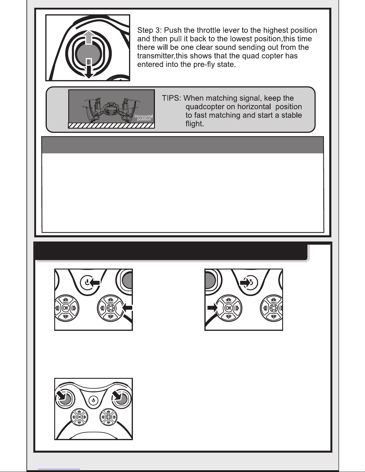
READY TO FLY YOUR QUADCOPTER
High/Low
speed switch
Battery cover
4x1.5V batteries
Left control
lever
Trimming
& resetting
Left Fine-tuning
Right Fine-tuning
Mode
switch
Right control
lever
ON/OFF
power and indicator
3D Eversion
Page 4
-3-
A B
CAUTIONS
MODE SWITCH & TRIMMING RESET FUNCTION
1.When the indicator of the transmitter appears eternal bright,however,the indicator
of the quadcopter appers slow flashing, this means that decoding is not successful.
This time please disconnect the power both of the quad copter and transmitter,then
repeat the pre-flying steps.
2.If the quadcopter is tilting to one side abruptly or spining while hoveing, please switch
off the power both of the quadcopter and transmitter and then repeat the pre-flying
steps.
3.When the indicator of the quadcopter keeps flashing slowly, it means that the quad
copter has entered into the low voltage protection state.This time you need to charge
the quadcopter.
Mode swith function:
Keep pressing the button A, then switch on
the power of the transmitter, your can select
Mode 1 or Mode 2.
Resetting function:
Keep pressing the button B, then switch on
the power of thetransmitter. Enter into the
Trimming &Resetting Mode(It is highly
suggested that the freshman should reset
the trummer first before starting the first flight.)
Level calibration function:
If quadcopter always fly to a side when starting, please
re-match signal and place it on a horizontal plane. Than
turn the two levers to the lower right comer(as left image)
for seconds, when indicator keep light up, it finshes auto
level calibration.
Page 5

-4-
MODE 1
ILLUSTRATION ON CONTROLL THE QUADCOPTER
(MODE 1, DEFAULTED MODE WHEN STARTING)
Page 6

-5-
MODE 2
ILLUSTRATION ON HOW TO CONTROL THE
QUADCOPTER (MODE 2)
Page 7

-6-
3 meters
FLIGHT CONTROL
3D EVERSION AND THROWING FLIGHT
INSTRUCTIONS
1.When you are familiar with the basic
operation, you can play some
awesome & thrilling stunt operation.
First of all, fly the four-axial aircraft to
the height of about or more than 3
meters, press the 3D Eversion switch
on the right above of the transmitter,
then right above of the transmitter,
and push the right rudder (in any
direction) at the same tone then you can
make 360 degree 3D tumbling operation
in any direction and make successive
tumbling stunt performance as well.
Page 8

-7-
BATTERY CHARGING
Caution:
1.Please pull out the charging wire before
shutting down the computer when charging
by the computer .
2.Please make sure the polarity connecting
is correctly when connecting the USB wire
to the battery ,and make sure the polarity
can not be upside or down.
Charging time: about 30 minutes ; Flying time: about 5 minutes.
Page 9

-8-
All the sare parts below can bought from local distributor.
X2-01A X2-02A
X2-03 X2-04
X2-06
X2-07
X2-05
X2-08
Upper body-Red
X2-01B
Upper body-Black
Motor B Battery
Lower body-Red
X2-02B
Lower body-Black
Blades Motor A
Circuit board USB charger wire
X2-09
Transmitter
TROUBLE SHOOTING
Page 10

-9-
06
04
05
07
01
02
03
Code Description Quantity Code Description Quantity Code Description Quantity
Upper body
Receiver board
Rotating motor
Rotating blade
Reversing blade
Transparent piece
Battery
1
1
2
2
2
1
1
08
Receiver motor
2
09
Lower body
1
09
03
02
01
05
07
08
06
04
BREAKDOWN & DIAGRAM
Page 11

-10-
95mm 95mm
95mm
35mm
MAIN PARAMETER
3.7V/150mAh
95mm
95mm
35mm
Page 12

 Loading...