

Sym Joyride 125, Joyride 200i EVO, X'PRO RV125, 200 EFi, Joyride 125 EVO Service Manual
...Page 1
Foreword
How to Use This Manual
Contents
Mechanism Illustration
Joyride 125 / 200i EVO
X’PRO RV125 / 200 EFi
SERVICE MANUAL
Page 2

Homepage
Contents
Foreword
This service manual contains the technical data of each component inspection
and repair for the Sanyang JOYRIDE 125/200i EVO, X’PRO RV 125/200 EFi
motorcycle. The manual is shown with illustrations and focused on “Service
Procedures”, “Operation Key Points”, and “Inspection Adjustment” so that
provides technician with service guidelines.
If the style and construction of the motorcycle, JOYRIDE 125/200i EVO, X’PRO
RV 125/200 EFi, are different from that of the photos, pictures shown in this
manual, the actual vehicle shall prevail. Specifications are subject to change
without notice.
Service Department
Sanyang Industry Co., LTD.
Page 3
Homepage
Contents
How to Use This Manual
This service manual describes basic information of different system parts and
system inspection & service for Sanyang JOYRIDE 125/200i EVO, X’PRO RV
125/200 EFi motorcycles. In addition, please refer to the manual contents in
detailed for the model you serviced in inspection and adjustment.
The first chapter covers general information and trouble diagnosis.
The second chapter covers service maintenance information.
Th third to the thirteenth chapter covers the engine and driving systems.
The fourteenth to the seventeenth is contained the parts set of assembly body.
The eighteenth chapter is electrical equipment.
The nineteenth chapter is special tool.
The twentieth chapter is wiring diagram
Please see index of content for quick having the special parts and system
information.
There are 4 buttons, “Foreword”, “Contents”, “How to Use This Manual” and
“Mechanism Illustration” in the PDF version, and can be access to these items
by clicking on the buttons.
If user wants to look for the content of each chapter, selecting the words of
each chapter on the contents can reach to each chapter. There are two buttons,
“Homepage and contents, on the top line of first page of the each chapter. Thus,
if the user needs to check other chapters, he can click the top buttons to back
the homepage or contents. The content of each chapter can be selected too.
Therefore, when needs to checking the content inside of the chapter, click the
content words of the chapter so that can back to the initial section of the
content. In addition, there is a “To this Chapter Contents” button at the second
page of each content so that clicking the button can back to the contents of this
chapter.
Page 4
Homepage
Contents
Contents
Page Content Index
1-1 ~ 1-20 General Information
1
2-1 ~ 2-12 Maintenance Information
3-1 ~ 3-8 Lubrication System
4-1 ~ 4-12 Fuel System-Carburetor
5-1 ~ 5-56 Fuel Injection System
6-1 ~ 6-14 Engine Removal
7-1 ~ 7-14 Cylinder Head / Valve
8-1 ~ 8-8 Cylinder / Piston
9-1 ~ 9-14 V-Belt Drive System
10-1 ~ 10-8 Final Drive Mechanism
11-1 ~ 11-8 AC Generator / Starting Clutch
2
3
4
5
6
7
8
9
10
11
12-1 ~ 12-8 Crankshaft / Crankcase
13-1 ~ 13-12 Cooling System
14-1 ~ 14-10 Body Cover
15-1 ~ 15-10 Brake System
16-1 ~ 16-12 Steering / Front Wheel / Front Cushion
17-1 ~ 17-6 Muffler / Rear Wheel / Rear Cushion
18-1 ~ 18-22 Electrical System
19-1 ~ 19-12 Special Tools
20-1 ~ 20-4 Wiring Diagram
12
13
14
15
16
17
18
19
20
Page 5
Home page
Contents
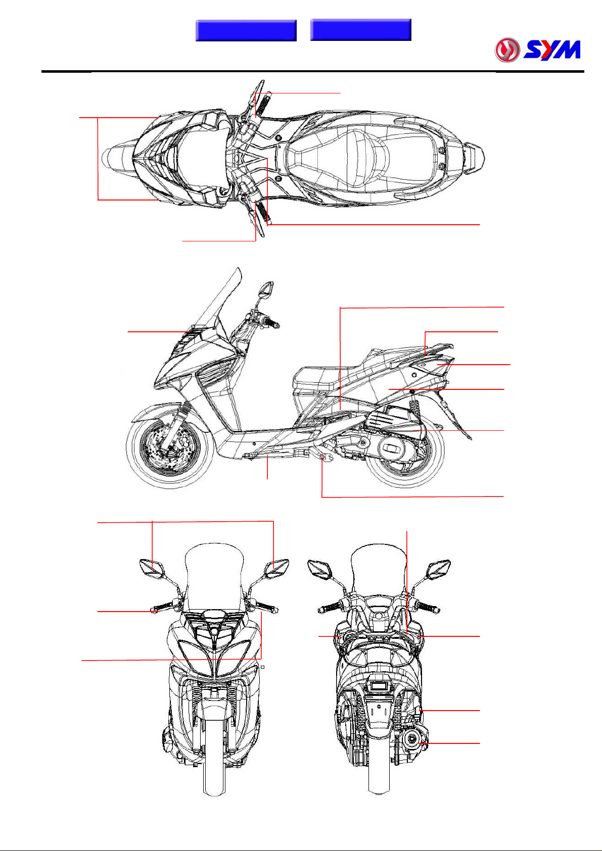
Mechanism Illustration
Light switch / start switch /
engine stop (hazard) switch
Front winker
Fuel tank /
Dimmer switch / winker switch /
horn switch / seat open (passing)
switch
fuel pump
ECU /
throttle body
Coolant filler
cap
Ignition / Seat open
switch
Front brake
lever
Rear brake
lever
Side stand
Fuel tank
cap
Taillight /
rear winker
Luggage box
Air cleaner
Main stand
Main switch
Reserved tank
cap
Battery
Muffler
Page 6
Homepage
Contents
1. GENERAL INFORMATION
Symbols and Marks .............................. 1-1
General Safety....................................... 1-2
Service Precautions.............................. 1-3
Specifications ........................................ 1-5
Cables and Harness Routing..............1-11
Troubleshooting-Carburetor model ...1-12
Troubleshooting-EFi model ................1-16
Lubrication Points ...............................1-20
Torque Values ....................................... 1-9
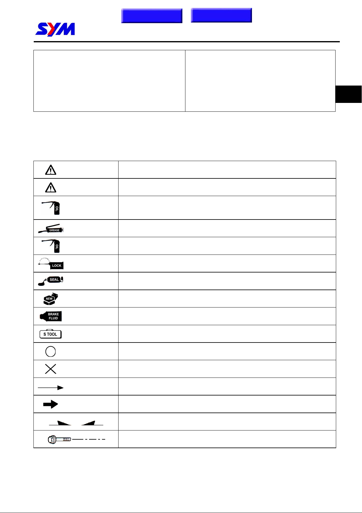
Symbols and Marks
Symbols and marks are used in this manual to indicate what and where the special service are
needed, in case supplemental information is procedures needed for these symbols and marks,
explanations will be added to the text instead of using the symbols or marks.
Warning
Caution
Engine oil
Grease King Mate G-3 is recommended.
Means that serious injury or even death may result if procedures are not
followed.
Means that equipment damages may result if procedures are not
followed.
Limits to use SAE 20 JASO FC class oil. Warranty will not cover the
damage that caused by not apply with the limited engine oil.
(Recommended oil: MAX-2 serial oils)
1
Gear oil
Locking sealant
Oil seal Apply with lubricant.
Renew Replace with a new part before installation.
Brake fluid Use recommended brake fluid DOT3 or WELLRUN brake fluid.
Special tools Special tools.
correct Meaning correct installation.
wrong Meaning wrong installation.
Indication Indication of components.
directions Indicates position and operation directions.
King Mate gear oil serials are recommended. (Bramax HYPOID GEAR
OIL # 140)
Apply sealant, medium strength sealant should be used unless
otherwise specified.
Components assembly directions each other.
Indicates where the bolt installation direction, --- means that bolt cross
through the component (invisibility).
1-1
Page 7
To this chapter contents
1. GENERAL INFORMATION
General Safety
Carbon monoxide
If you must run your engine, ensure the place is
well ventilated. Never run your engine in a
closed area. Run your engine in an open area, if
you have to run your engine in a closed area, be
sure to use an extractor.
Caution
Exhaust contains toxic gas which may cause
one to lose consciousness and even result in
death.
Gasoline
Gasoline is a low ignition point and explosive
material. Work in a well-ventilated place, no
flame or spark should be allowed in the work
place or where gasoline is being stored.
Caution
Gasoline is highly flammable, and may
explode under some conditions, keep it away
from children.
Battery
Caution
‧ Battery emits explosive gases; flame is
strictly prohibited. Keep the place well
ventilated when charging the battery.
‧ Battery contains sulfuric acid (electrolyte)
which can cause serious burns so be
careful do not be spray on your eyes or
skin. If you get battery acid on your skin,
flush it off immediately with water. If you get
battery acid in your eyes, flush it off
immediately with water and then go to
hospital to see an ophthalmologist.
‧ If you swallow it by mistake, drink a lot of
water or milk, and take some laxative such
as castor oil or vegetable oil and then go to
see a doctor.
‧ Keep electrolyte beyond reach of children.
Brake shoe
Do not use an air hose or a dry brush to clean
components of the brake system, use a vacuum
cleaner or the equivalent to avoid dust flying.
Used engine oil
Caution
Prolonged contact with used engine oil (or
transmission oil) may cause skin cancer
although it might not be verified.
We recommend that you wash your hands
with soap and water right after contacting.
Keep the used oil beyond reach of children.
Hot components
Caution
Components of the engine and exhaust
system can become extremely hot after
engine running. They remain very hot even
after the engine has been stopped for some
time. When performing service work on these
parts, wear insulated gloves and wait until
cooling off.
Caution
Inhaling brake shoe or pad ash may cause
disorders and cancer of the breathing system.
Brake fluid
Caution
Spilling brake fluid on painted, plastic, or
rubber parts may cause damage to the parts.
Place a clean towel on the above-mentioned
parts for protection when servicing the brake
system. Keep the brake fluid beyond reach of
children.
1-2
Page 8
1. GENERAL INFORMATION
Service Precautions
To this chapter contents
z Always use with Sanyang genuine parts and
recommended oils. Using non-designed parts
for Sanyang motorcycle may damage the
motorcycle.
z Special tools are designed for remove and
install of components without damaging the
parts being worked on. Using wrong tools
may result in parts damaged.
z When servicing this motorcycle, use only
metric tools. Metric bolts, nuts, and screws
are not interchangeable with the English
system, using wrong tools and fasteners may
damage this vehicle.
z Clean the outside of the parts or the cover
before removing it from the motorcycle.
Otherwise, dirt and deposit accumulated on
the part's surface may fall into the engine,
chassis, or brake system to cause a damage.
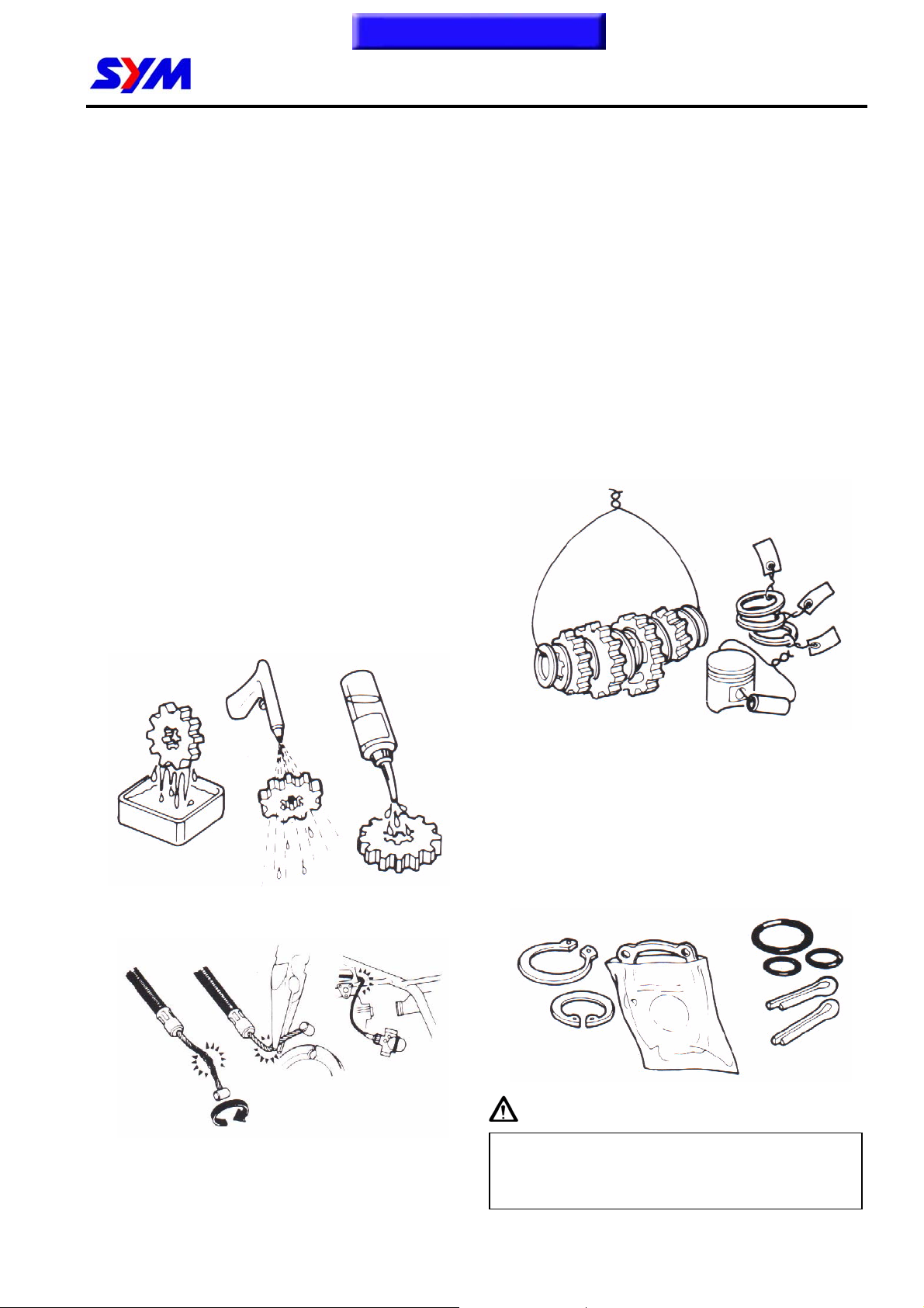
z Wash and clean parts with high ignition point
solvent, and blow dry with compressed air.
Pay special attention to O-rings or oil seals
because most cleaning agents have an
adverse effect on them.
z Never bend or twist a control cable to prevent
unsmooth control and premature worn out.
z Rubber parts may become deteriorated when
old, and prone to be damaged by solvent and
oil. Check these parts before installation to
make sure that they are in good condition,
replace if necessary.
z When loosening a component which has
different sized fasteners, operate with a
diagonal pattern and work from inside out.
Loosen the small fasteners first. If the bigger
ones are loosen first, small fasteners may
receive too much stress.
z Store complex components such as
transmission parts in the proper assemble
order and tie them together with a wire for
ease of installation later.
z Note the reassemble position of the important
components before disassembling them to
ensure they will be reassembled in correct
dimensions (depth, distance or position).
z Components not to be reused should be
replaced when disassembled including
gaskets metal seal rings, O-rings, oil seals,
snap rings, and split pins.
Caution
In addition to damaging paint finish, brake oil
can also damage the structural integration of
plastic or rubber parts.
1-3
Page 9
To this chapter contents
1. GENERAL INFORMATION
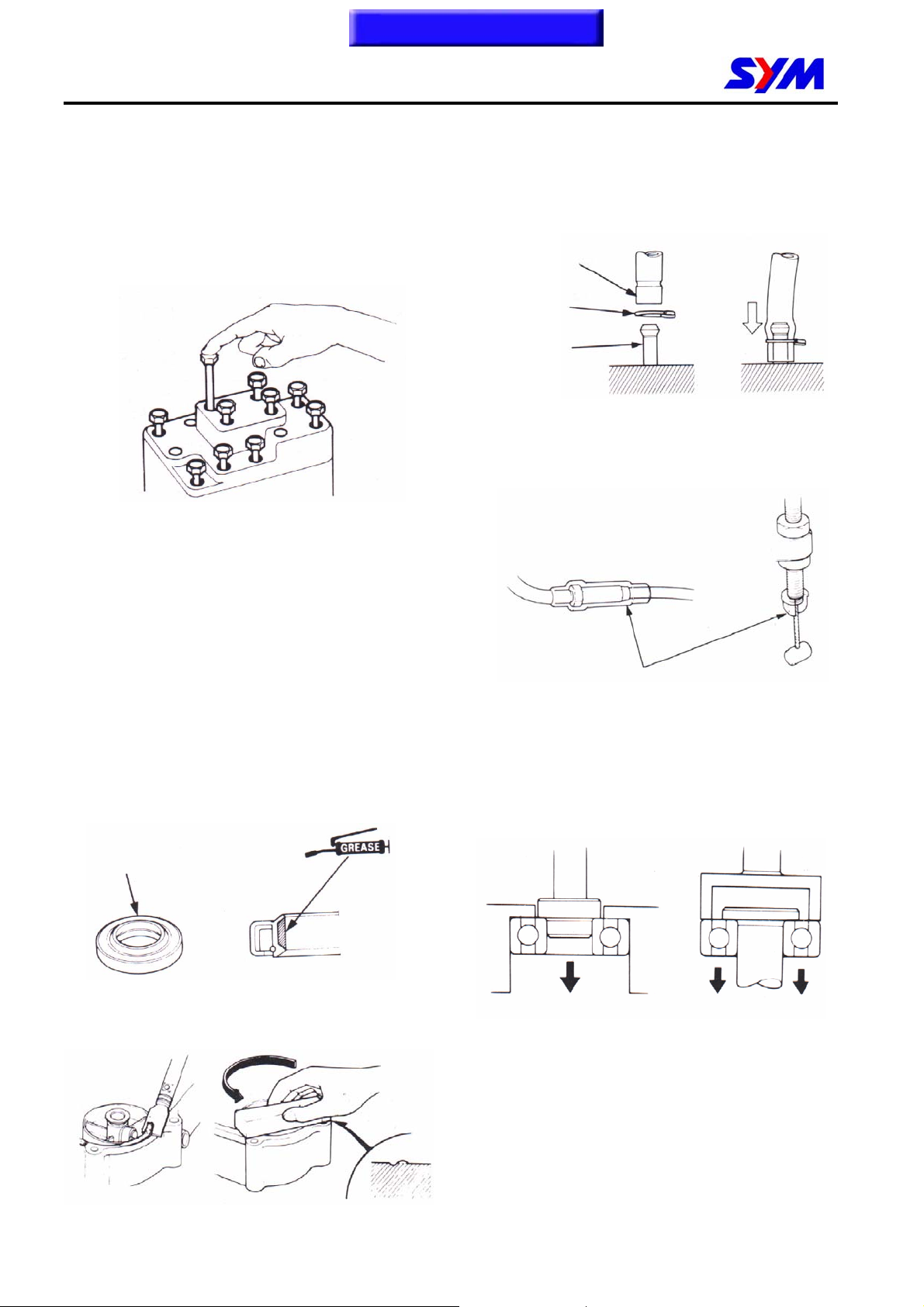
z The length of bolts and screws for assemblies,
cover plates or boxes is different from one
another, be sure they are correctly installed.
In case of confusion, Insert the bolt into the
hole to compare its length with other bolts, if
its length out side the hole is the same with
other bolts, it is a correct bolt. Bolts for the
same assembly should have the same length.
z Tighten assemblies with different dimension
fasteners as follows: Tighten all the fasteners
with fingers, then tighten the big ones with
special tool first diagonally from inside toward
outside, important components should be
tightened 2 to 3 times with appropriate
increments to avoid warp unless otherwise
indicated. Bolts and fasteners should be kept
clean and dry. Do not apply oil to the threads.
z When oil seal is installed, fill the groove with
grease, install the oil seal with the name of
the manufacturer facing outside, check the
shaft on which the oil seal is to be installed for
smoothness and for burrs that may damage
the oil seal.
Manufacturer's
name
z Remove residues of the old gasket or sealant
before reinstallation, grind with a grindstone if
the contact surface has any damage.
z The ends of rubber hoses (for fuel, vacuum,
or coolant) should be pushed as far as they
can go to their connections so that there is
enough room below the enlarged ends for
tightening the clamps.
Groove
Clamp
Connection
z Rubber and plastic boots should be properly
reinstalled to the original correct positions as
designed.
z The tool should be pressed against two (inner
Boots
and outer) bearing races when removing a
ball bearing. Damage may result if the tool is
pressed against only one race (either inner
race or outer race). In this case, the bearing
should be replaced. To avoid damaging the
bearing, use equal force on both races.
Both of these examples can result in bearing damage.
z Lubricate the rotation face as assembling.
Check if positions and operation for installed
parts is in correct and properly.
1-4
Page 10
1. GENERAL INFORMATION
g
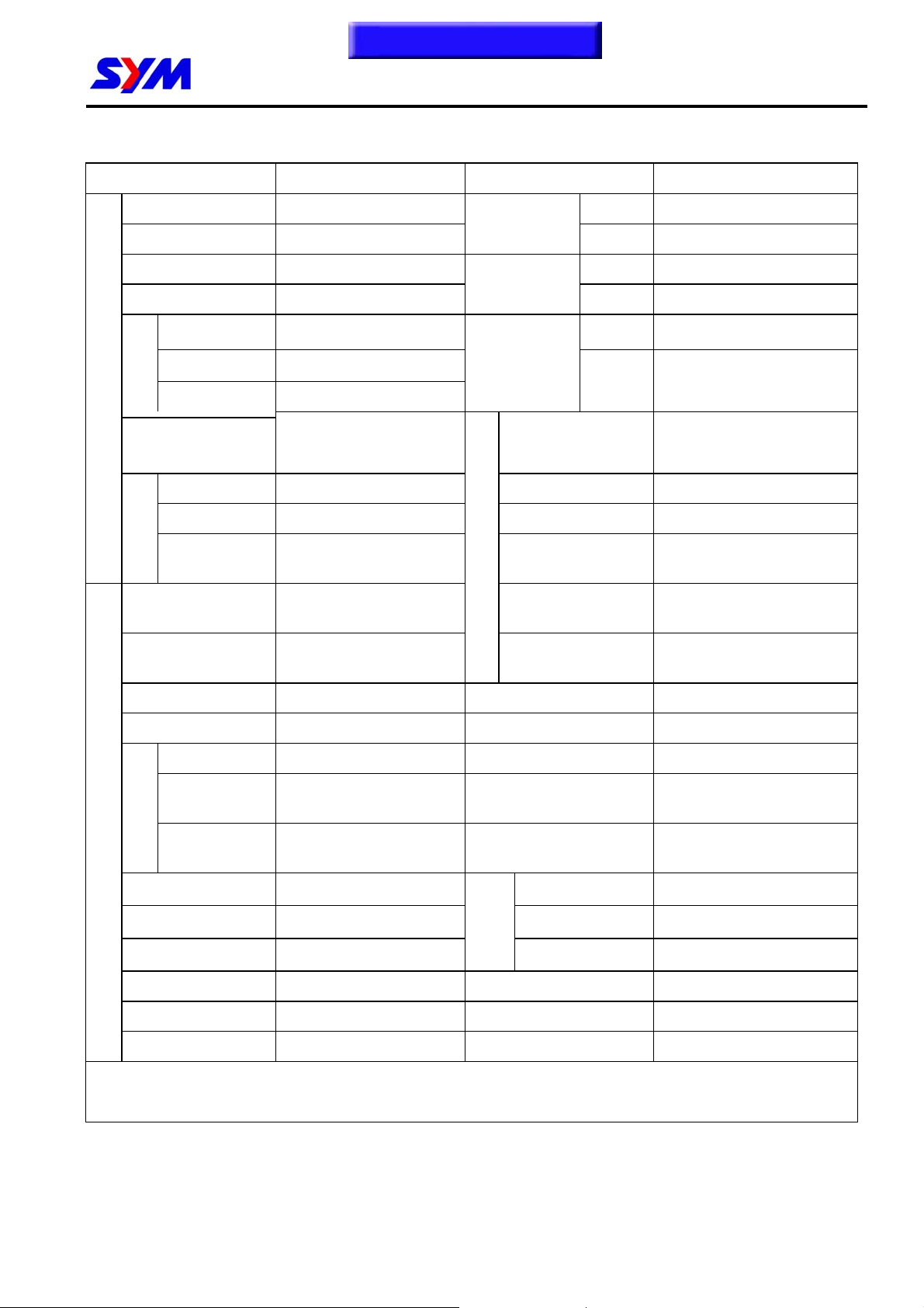
Specifications
Maker SANYANG MODEL LF12W-6/F
To this chapter contents
Overall Length 2100 mm Front Telescopic Fork
Overall Width 760 mm
Overall Height 1390 mm Front 110 / 90-13 56P
Wheel Base 1440 mm
Front 63 kg Front
ht
Curb
Passengers/
WEIGHT DIMENSION
Total Weight
Position and
arrangement
Rear 93 kg
Wei
Total 156 kg
Two /170 kg Max. Speed >100 km/hr
Weight
Front 97 kg Climb Ability 28°
Rear 229 kg Primary Reduction Belt
Total 326 kg
Type Gasoline Clutch
Horizontal, below
center, CYL incline 80°
Suspension
System
Tire
Specifications
Brake System
Secondary
Reduction
PERFORMANCE
Transmission C.V.T.
Rear Unit Swing
Rear 130 / 70-12 64L
Disk (ψ273mm)
Rear
Disk (ψ200mm)
Gear
3-piece centrifugal, dry
type
Fuel Used >92 Unleaded gasoline Speed meter 0 ~ 140 km/hr
Cycle/Cooling 4-stroke/water cooled Horn 93 – 112 dB/A
Bore Ø 57 mm Muffler Expansion & Pulse Type
Stroke 48.8 mm
Cylinder
ENGINE
Number/Arran
gement
Displacement 124.5 cc Co
Compression Ratio 10.5 : 1 HC
Max. HP 13 ps / 8500 rpm
Max. Torque 1.1 kg-m / 6500 pm E.E.C. -
Ignition C.D.I P.C.V. -
Starting System Kick & Electrical Starter Catalytic Converter Equipped
Single Cylinder Lubrication System
Exhaust Pipe Position
and Direction
Exhaust
Concentratio
n
NOx
Right Side & Backward
Forced Circulation &
Splashing
〈 2.0 g/km
〈 0.8 g/km
〈 0.15 g/km
1-5
Page 11
g
To this chapter contents
1. GENERAL INFORMATION
Specifications
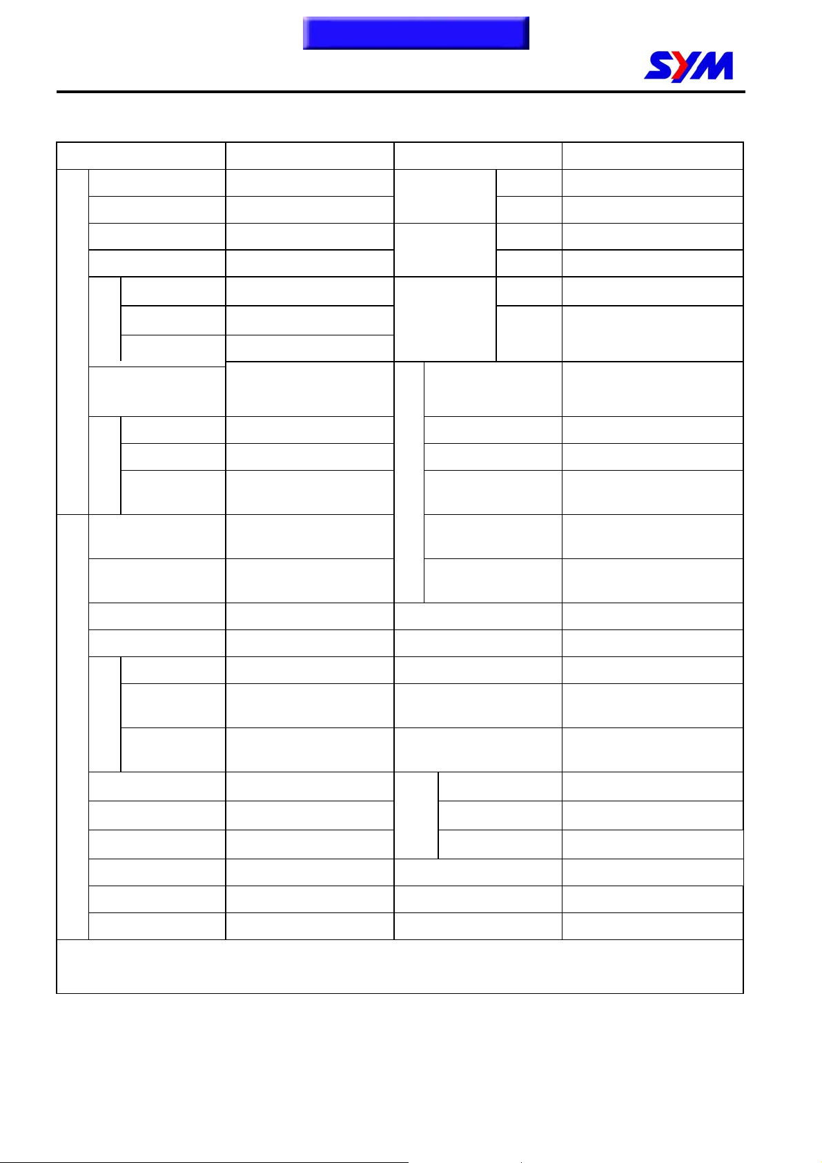
Maker SANYANG MODEL LF12W2-7
Overall Length 2100 mm Front TELESCOPIC FORK
Overall Width 760 mm
Overall Height 1390 mm Front 110 / 90-13 56P
Wheel Base 1440 mm
Front 63 kg Front
ht
Curb
WEIGHT DIMENSION
Total Weight
arrangement
Rear 93 kg
Wei
Total 156 kg
Passengers/
Weight
Front 97 kg Climb Ability 28°
Rear 229 kg Primary Reduction BELT
Total 326 kg
Type Gasoline Clutch
Position and
Two /170 kg Max. Speed >100 km/hr
Horizontal, below
center, CYL incline 80°
Suspension
System
Tire
Specifications
Brake System
Secondary
Reduction
PERFORMANCE
Transmission C.V.T.
Rear Unit SWING
Rear 130 / 70-12 64L
DlSK (ψ273mm)
Rear
DlSK (ψ200mm)
GEAR
3-piece centrifugal, dry
type
Fuel Used >92 Unleaded gasoline Speed meter 0 ~ 140 km/hr
Cycle/Cooling 4-stroke/water cooled Horn 93 – 112 dB/A
Bore Ø 57 mm Muffler Expansion & Pulse Type
Stroke 48.8 mm
Cylinder
ENGINE
Number/Arran
gement
Displacement 124.5 cc Co
Compression Ratio 10.5 : 1 HC
Max. HP 13 ps / 8500 rpm
Max. Torque 1.1 kg-m / 6500 pm E.E.C. -
Ignition Full Transistor Ignition P.C.V. Equipped
Starting System Electrical Starter Catalytic converter Equipped
Single Cylinder Lubrication System
Exhaust Pipe Position
and Direction
Exhaust
Concentratio
n
NOx
Right Side & Backward
Forced pressure and wet
sump
〈 2.0 g/km
〈 0.8 g/km
〈 0.15 g/km
1-6
Page 12
1. GENERAL INFORMATION
Specifications
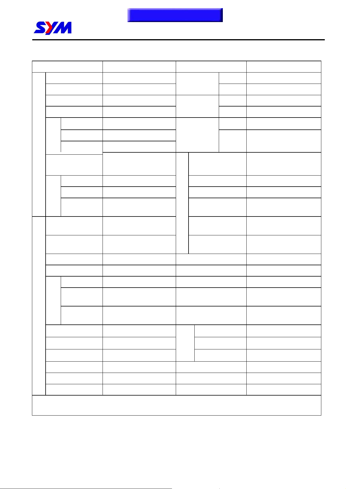
Maker SANYANG MODEL LF18W-A/W3-H/W5-C
To this chapter contents
Overall Length 2100 mm Front TELESCOPIC FORK
Overall Width 760 mm
Overall Height 1390 mm Front 110 / 90-13 56P
Wheel Base 1440 mm
Front 63 kg Front
Net
Passengers/
WEIGHT DIMENSION
Total Weight
Position and
arrangement
Rear 93 kg
Weight
Total 156 kg
Two /170 kg Max. Speed >109 km/hr
Weight
Front 97 kg Climb Ability 28°
Rear 229 kg Primary Reduction BELT
Total 326 kg
Type Gasoline Clutch
Horizontal, below center,
CYL incline 80°
Suspension
System
Tire
Specifications
Brake System
Secondary
Reduction
PERFORMANCE
Transmission C.V.T.
Rear UNlT SWING
Rear 130 / 70-12 64L
DlSK (ψ273mm)
Rear
DlSK (ψ200mm)
GEAR
3-piece centrifugal, dry
type
Fuel Used >92 Unleaded gasoline Speed meter 0 ~ 140 km/hr
Cycle/Cooling 4-stroke/water cooled Horn 93 – 112 dB/A
Bore Ø 61 mm Muffler Expansion & Pulse Type
Stroke 58.6 mm
Cylinder
ENGINE
Number/Arran
gement
Displacement 171.2 cc Co
Compression Ratio 10 : 1 HC
Max. HP 13 / 8000 ps/rpm
Max. Torque 1.2 / 6000 kg-m/rpm E.E.C. -
Ignition C.D.I. P.C.V. Equipped
Starting System Kick & Electrical Starter Catalytic converter Equipped
Single Cylinder Lubrication System
Exhaust Pipe Position
and Direction
Exhaust
Concentratio
n
NOx
Right Side & Backward
Forced pressure and wet
sump
〈 12.0 g/km
〈 1.0 g/km
-
1-7
Page 13
g
To this chapter contents
1. GENERAL INFORMATION
Specifications
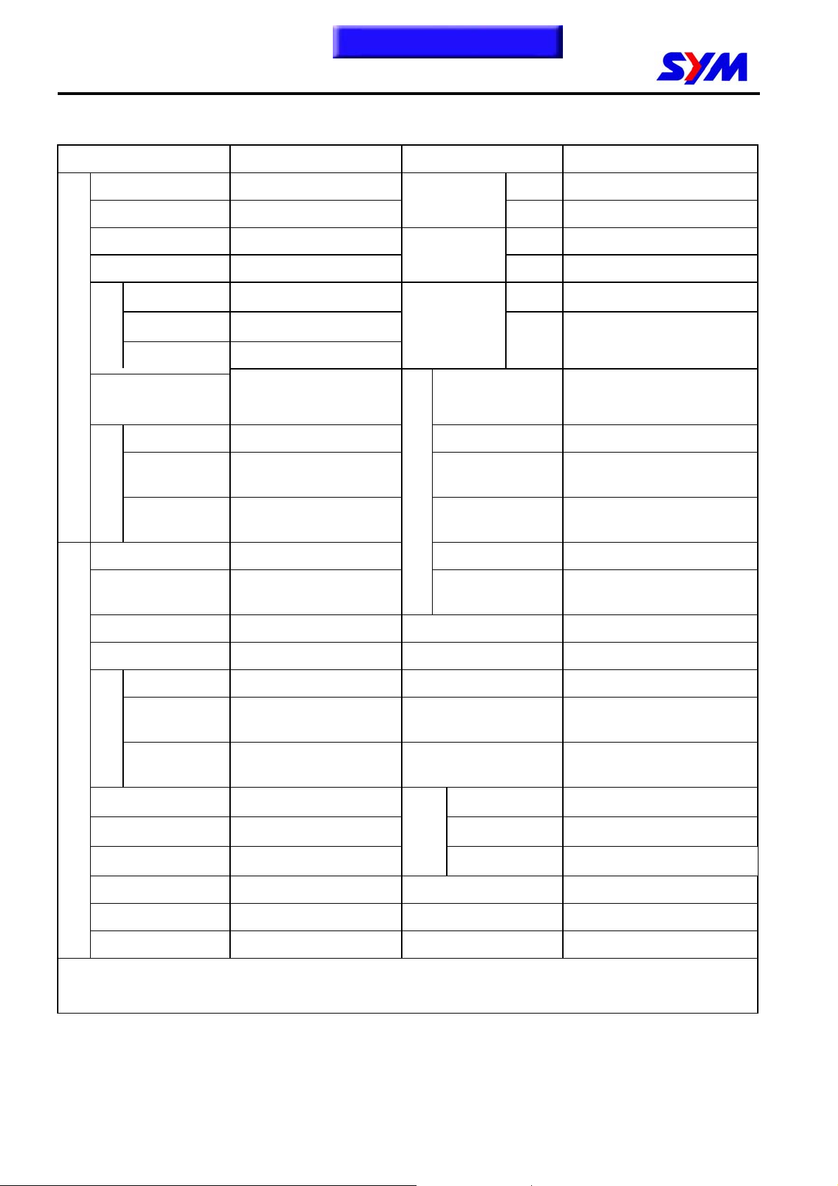
Maker SANYANG MODEL LF18W-6/W1-9/W2-7/W4-8
Overall Length 2100 mm Front TELESCOPIC FORK
Overall Width 760 mm
Overall Height 1390 mm Front 110 / 90-13 56P
Wheel Base 1440 mm
Front 63 kg Front
ht
Curb
Passengers/
WEIGHT DIMENSION
Total Weight
arrangement
Rear 93 kg
Wei
Total 156 kg
Two /170 kg Max. Speed >109 km/hr
Weight
Front 97 kg Climb Ability 28°
Rear 229 kg
Total 326 kg
Type Gasoline Clutch 3-piece centrifugal, dry type
Position and
Horizontal, below
center, CYL incline 80°
Suspension
System
Tire
Specifications
Brake System
Primary
Reduction
Secondary
Reduction
PERFORMANCE
Transmission C.V.T.
Rear UNlT SWING
Rear 130 / 70-12 64L
DlSK (ψ273mm)
Rear
DlSK (ψ200mm)
BELT
GEAR
Fuel Used >92 Unleaded gasoline Speed meter 0 ~ 140 km/hr
Cycle/Cooling 4-stroke/water cooled Horn 93 – 112 dB/A
Bore Ø 61 mm Muffler Expansion & Pulse Type
Stroke 58.6 mm
Cylinder
Number/Arran
ENGINE
Compression Ratio 10 : 1 HC
Starting System Electrical Starter Catalytic converter Equipped
gement
Displacement 171.2 cc Co
Max. HP 15 / 8000 ps/rpm
Max. Torque 1.35 / 6500 kg-m/rpm E.E.C. -
Ignition Full Transistor Ignition P.C.V. - / Equipped
Single Cylinder Lubrication System
Exhaust Pipe Position
and Direction
Exhaust
Concentratio
n
NOx
Right Side & Backward
Forced pressure and wet
sump
〈 2.0 g/km
〈 0.3 g/km
〈 0.15 g/km
1-8
Page 14
1. GENERAL INFORMATION
Torque Values
Item Q’ty
To this chapter contents
Thread Dia.
(mm)
Torque Value
Remarks
(Kgf-m)
Cylinder head bolt
Valve clearance adjust nut
Spark plug
L. Crankcase cover bolts
Crankcase bolts
Oil drain bolt
Oil strainer cap
Gear oil drain bolt
Gear oil inspection bolt
Transmission cover bolt
Flywheel bolt
Clutch driving plate bolt
Driving disc nut
Clutch outer cover nut
Transmission cover bolts
Stopper nut for engine hanger
bracket
Nut for engine hanger bracket
Bolt for engine hanger bracket
Engine mounting bolt
Front wheel shaft nut
Rear wheel shaft nut
Bolt for rear shock absorber (upper)
Bolt for rear shock absorber (under)
Bolt for steering rod
Front shock absorber
Brake arm bolts
Brake hose bolts
Bolt for brake caliper
Bolts for the lining guide pin
Brake disk bolts
Mounting screw for speedometer
cable
Muffler bolts
Mounting bolts for exhaust pipe
connection
The torque values listed in above table are for more important tighten torque values. Please see
standard values for not listed in the table.
4 8 2.0-2.4
4 5 0.7-1.1
1 10 1.0-1.4
7 6 1.1-1.5
7 6 0.8-1.2
1 8 1.1-1.5
1 30 1.3-1.7
1 6 1.0-1.4
1 6 1.0-1.4
7 6 1.0-1.4
1 14 5.0-6.0
1 28 5.0-6.0
1 12 5.0-6.0
1 10 3.5-4.5
7 6 1.0-1.4
1 8 1.8-2.2
1 10 4.0-5.0
1 10 4.0-5.0
1 10 3.5-4.5
1 12 5.0-7.0
1 14 11.0-13.0
2 10 3.5-4.5
2 8 2.4-3.0
1 10 4.0-5.0
4 8 2.4-3.0
2 6 0.8-1.2
4 10 3.3-3.7
4 10 3.0-3.5
4 6 1.6-2.0
7 10 4.0-4.5
1 5 0.15-0.3
4 8 3.2-3.8
2 7 1.0-1.2
Apply oil to thread
1-9
Page 15
To this chapter contents
1. GENERAL INFORMATION
Standard Torque Values for Reference
Type Torque value kgf-m
5 mm Bolt, Nut 0.45 - 0.6
6 mm Bolt, Nut 0.8 - 1.2
8 mm Bolt, Nut 1.8 - 2.5
10 mm Bolt, Nut 3.0 - 4.0
12 mm Bolt, Nut 5.0 - 6.0
5 mm Screw 0.35 - 0.5
6 mm Screw & 6mm bolt with 8mm head 0.7 - 1.1
6 mm Flange bolt, nut 1.0 - 1.4
8 mm Flange bolt, nut 2.4 - 3.0
10 mm Flange bolt, nut 3.5 - 4.5
1-10
Page 16
1. GENERAL INFORMATION
Cables and Harness Routing
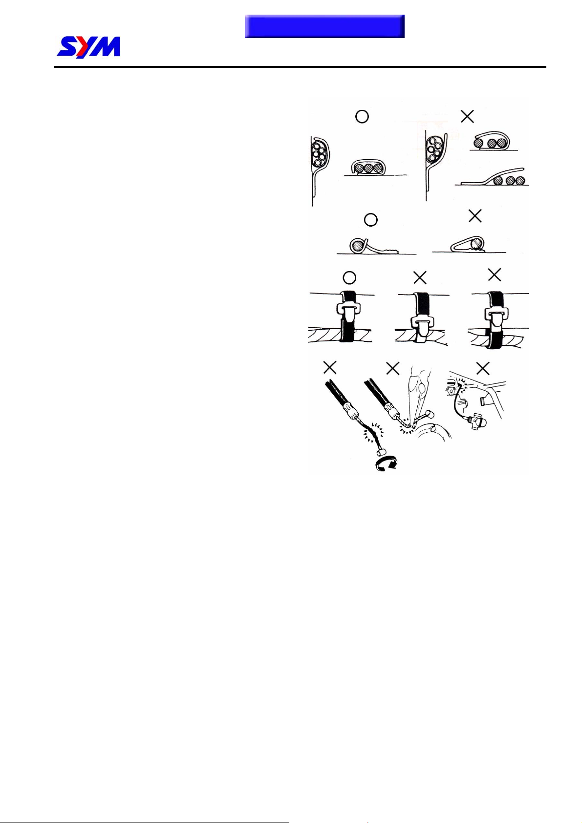
Note the following when routing cables
and wire harnesses:
• A loose wire, cable or harness may cause
safety hazard. After clamping, check each
wire to make sure it is secured.
• Do not squeeze wires against the weld or its
clamp.
• Secure wires and wire harnesses to the
frame with respective wire bands at the
designated locations. Tighten the bands so
that only the insulated surfaces contact the
wires or wire harnesses.
• Route harnesses so that they neither pull too
tight nor have excessive slack.
• Protect wires or wire harnesses with electrical
tape or tube if they contact a sharp edge or
corner.
• Route wire harnesses to avoid sharp edges
or corners.
• Avoid the projected ends of bolts and screws.
• Keep wire harnesses far away from the
exhaust pipes and other hot parts.
• Be sure grommets are seated in their groves
properly.
• After clamping, check each harness to be
certain that it is not interfered with any
moving or sliding parts.
• After routing, check that the wire harnesses
are not twisted or kink.
• Wire harnesses routed along the handlebar
should not be pulled too tight or have
excessive slack, be rubbed against or
interfere with adjacent or surrounding parts in
all steering positions.
• Thoroughly clean the surface where tape is to
be applied.
• Wrap electrical tape around the damaged
parts or replace them.
To this chapter contents
○:correct
╳:wrong
1-11
Page 17
r
p
To this chapter contents
1. GENERAL INFORMATION
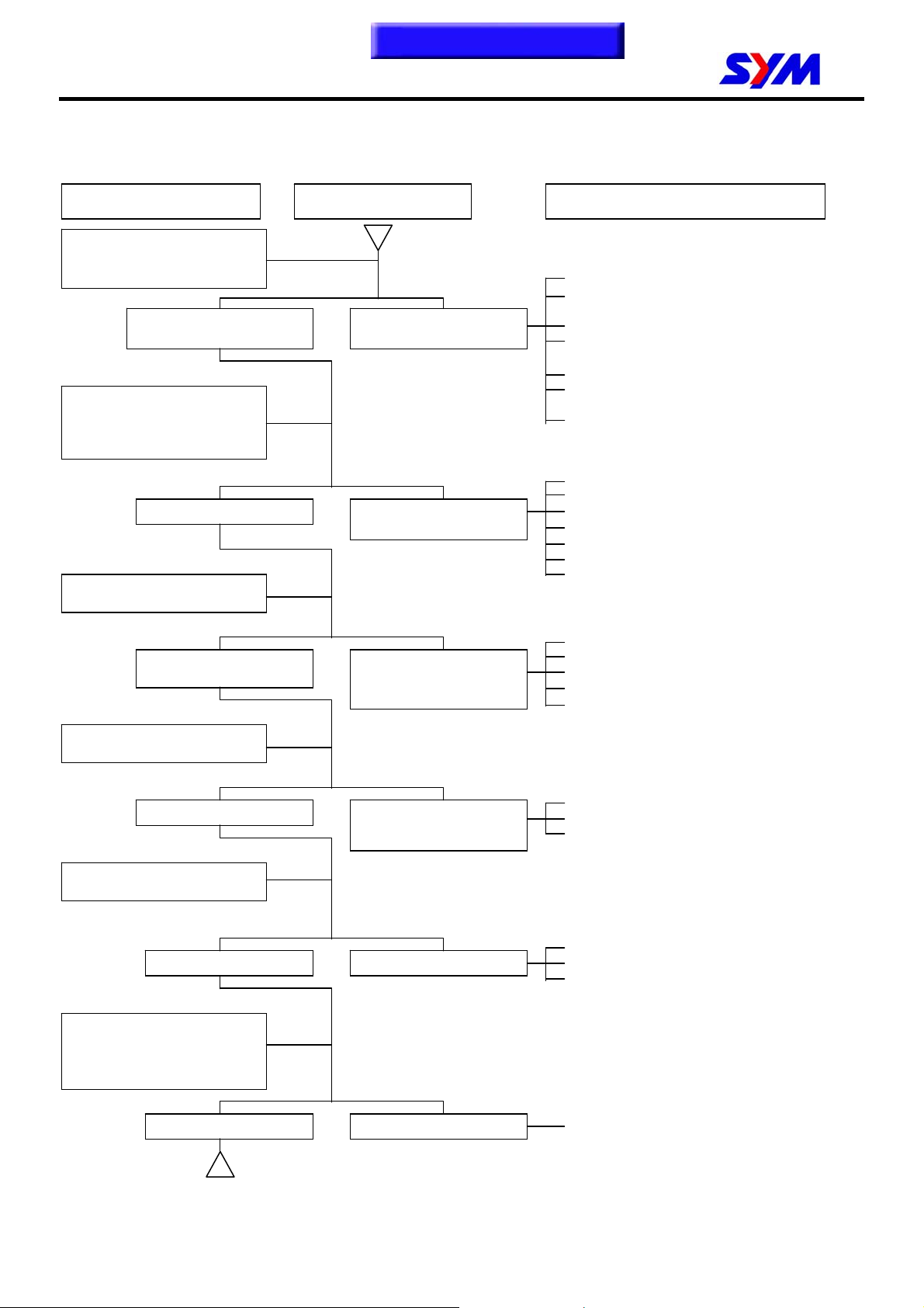
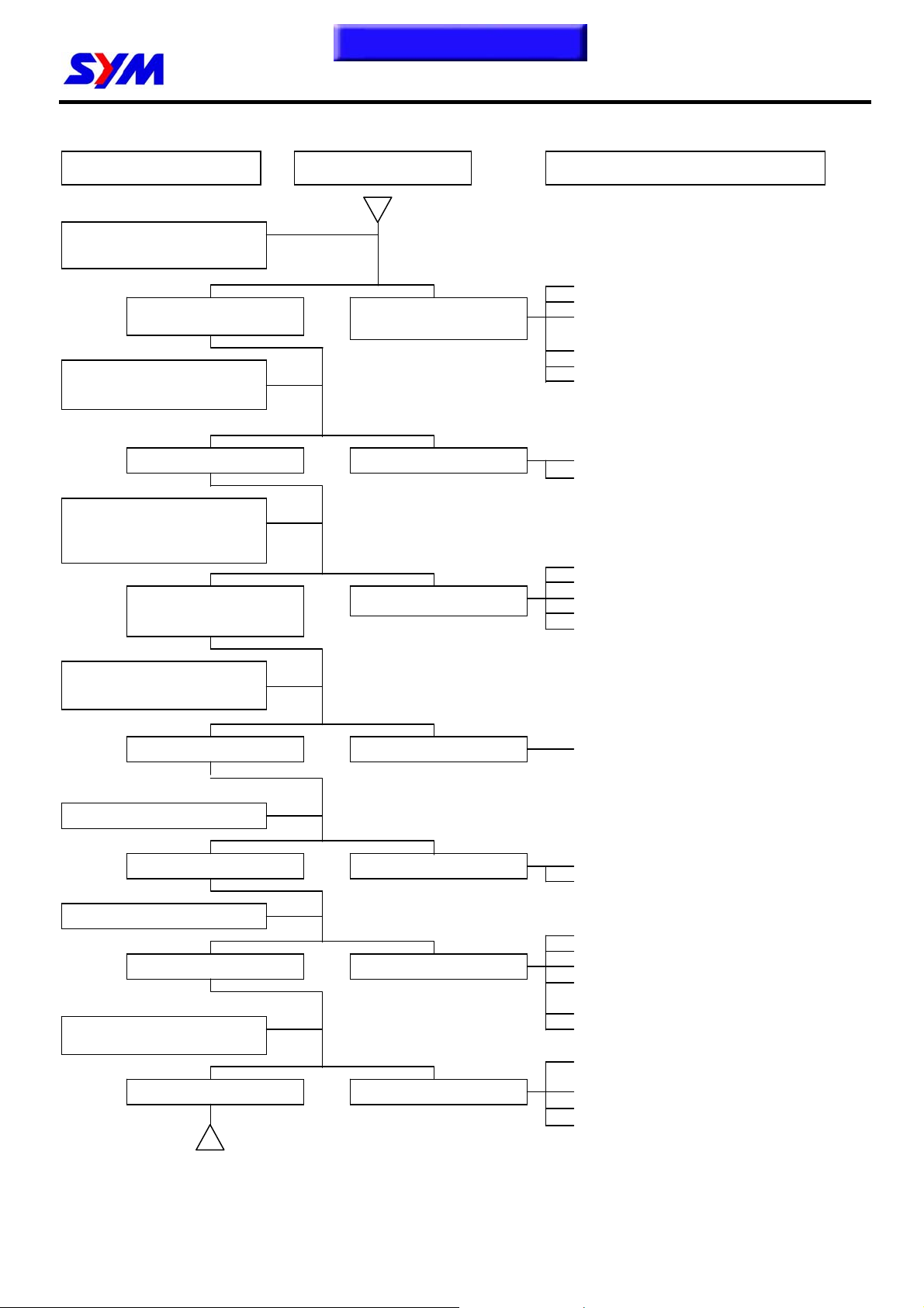
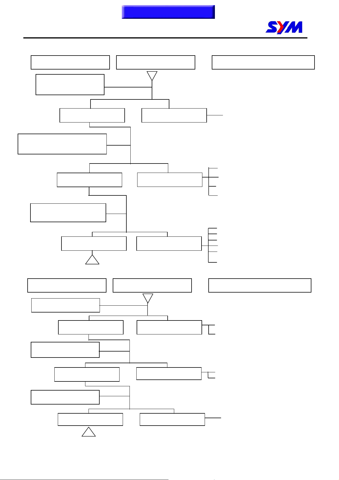
Troubleshooting-Carburetor model
A. Engine hard to start or can not be started
Check and adjustment Failure condition Possible causes
Loosen carburetor drain bolt
to check if there is gasoline
inside the carbureto
.
Fuel supplied to
carburetor sufficient.
Remove spark plug, install it
into spark plug cap, and
perform a spark test against
engine ground.
Check if sparks Weak sparks, no
Perform cylinder compression
pressure test.
No fuel is supplied to
carburetor.
s
ark at all.
1. No fuel in fuel tank
2. Check if the pipes, fuel tank to carburetor
and intake vacuum, are clogged.
3. Float valve clogged
4. Lines in fuel tank evaporation system
clogged
5. Malfunction of fuel pump
6. Loosen or damaged fuel pump vacuum
hose
7. Fuel filter clogged
1. Malfunction of spark plug
2. Spark plug foul
3. Malfunction of CDI set
4. Malfunction of AC generator
5. Ignition coil is in open or short circuit
6. Ignition coil leads open or short circuit
7. Malfunction of main switch
Cylinder compression
pressure normal.
Re-start by following the
starting procedures.
No ignition
Remove the spark plug again
and check it.
Dry spark plug Wet spark plug
Remove carburetor after 30
minutes and connect a hose
onto fuel rich circuit. Then
blow the hose with air.
Low compression
pressure or no
pressure.
There are some signs of
ignition, but engine can
not be started.
1. Piston ring seized
2. Malfunction of cylinder valves
3. Worn cylinder and piston ring
4. Cylinder gasket leak
5. Sand hole in compression parts
1. Malfunction of throttle valve operation
2. Air sucked into intake manifold
3. Incorrect ignition timing
1. Fuel level in carburetor too high
2. Malfunction of throttle valve operation
3. Throttle valve opening too wide
Blowing in normal Blowing clogged
1. Malfunction of automatic by- starter
1-12
Page 18
To this chapter contents
1. GENERAL INFORMATION
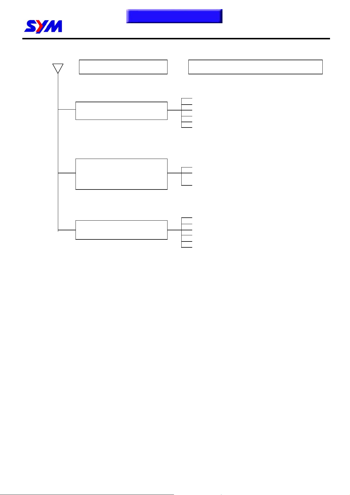
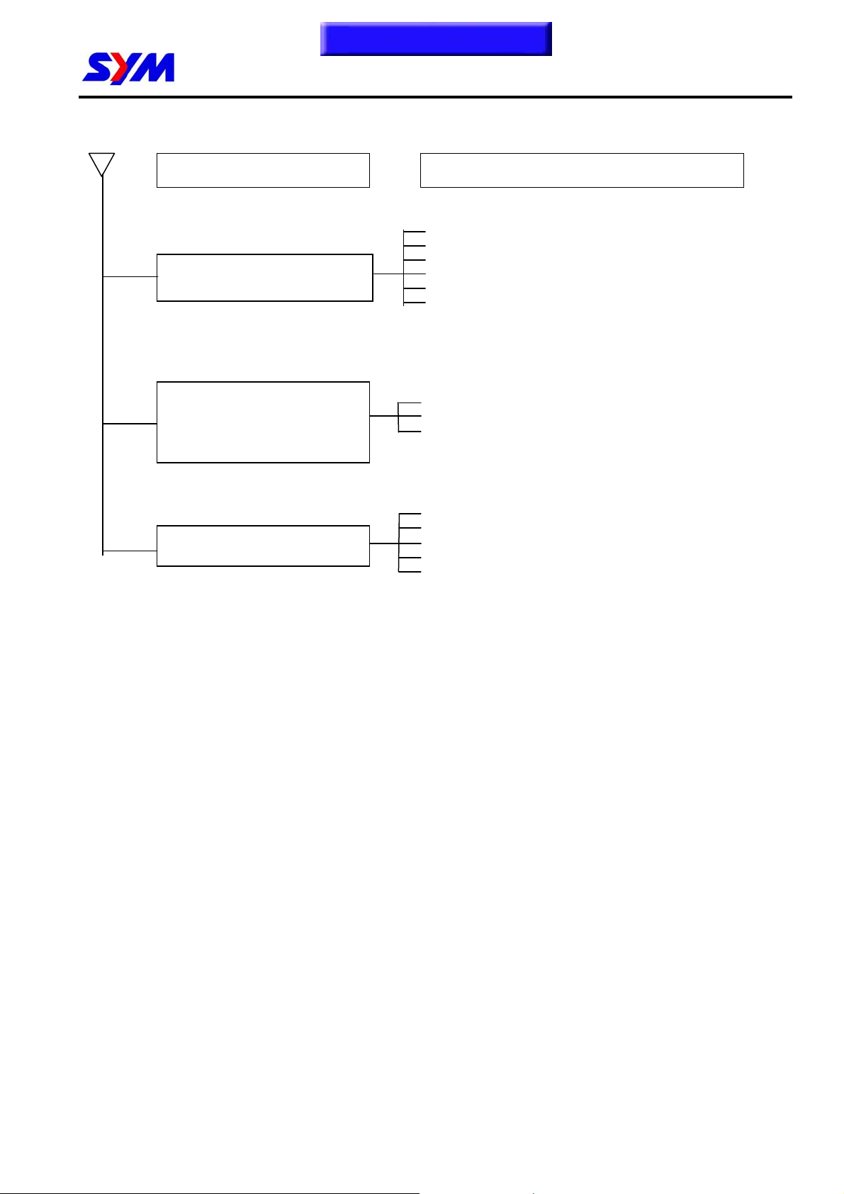
B. Engine run sluggish (Speed does not pick up, lack of power)
Check and adjustment Fault condition Probable causes
Try gradual acceleration and
check engine speed.
Check ignition timing
(Using ignition lamp)
Engine speed can be
increased.
Engine speed can not be
increased.
1. Air cleaner clogged
1. Poor fuel supply
2. Lines in fuel tank evaporation system
clogged
3. Exhaust pipe clogged
4. Fuel level too low in carburetor
5. Fuel nozzle clogged in carburetor.
Ignition timing correct Incorrect ignition timing
Check cylinder compression
pressure (using compression
pressure gauge)
Compression pressure
correct
Check if carburetor jet is
clogged
No clogged Clogged
Remove spark plug
No foul or discoloration Fouled and discoloration
No compression pressure
1. Malfunction of CDI
2. Malfunction of AC alternator
1. Cylinder & piston ring worn out
2. Cylinder gasket leaked
3. Sand hole in compression parts
4. Valve deterioration
5. Seized piston ring
1. Remove foreign
1. Remove dirt
2. Incorrect spark plug heat range
Check if engine over
Normal Engine overheat
Continually drive in
acceleration or high speed.
No knock Knock
1. Piston and cylinder worn out
2. Lean mixture
3. Poor fuel quality
4. Too much carbon deposited in
combustion chamber
5. Ignition timing too advanced
6. Poor circuit on the cooling system
1. Too much carbon deposited in
combustion chamber
2. Lean mixture
3. Poor fuel quality
4. Ignition timing too advanced
1-13
Page 19

To this chapter contents
1. GENERAL INFORMATION
C. Engine runs sluggish (especially in low speed and idling)
Check and adjustment Fault condition Probable causes
Check ignition timing
(Using ignition lamp)
Adjust the air screw of
carburetor
Normal Abnormal
Good Poor
Air sucked through
carburetor gasket
No air sucked Air sucked
Remove spark plug, install
spark plug into spark plug
cap and perform spark test
against engine ground.
Good spark Poor
D. Engine runs sluggish (High speed)
1. Incorrect ignition timing (malfunction
of CDI or AC alternator)
1. Rich mixture (loosen the screw)
2. Lean mixture (tighten the screw)
1. Poor heat insulation gasket
2. Carburetor lock loose
3. Poor intake gasket
4. Poor carburetor O-ring
5. Vacuum hose crack
1. Spark plug fouled
2. Malfunction of CDI
3. Malfunction of AC generator
4. Malfunction of ignition coil
5. Open or short circuit in spark plug
leads
6. Malfunction of main switch
Check and adjustment
Check ignition timing
Check for fuel supplying
system in automatic fuel cup
Normal Abnormal
Good Poor
Check if carburetor clogged
No clogged Clogged
1-14
Fault condition Probable causes
1. Malfunction of CDI
2. Malfunction of AC alternator
1. Insufficient fuel in fuel tank
2. Fuel filter clogged
3. Restricted fuel tank vent
1. Cleaning
Page 20
To this chapter contents
1. GENERAL INFORMATION
E. Clutch, Driving And Driving Pulley
FAULT CONDITIONS
PROBABLE CAUSES
Engine can be started but
motorcycle can not be moved.
1. Driving belt worn out or deformation
2. Driving disk damaged
3. Driving pulley spring broken
4. Clutch ling broken
5. Driving slide-shaft gear groove broken
6. Transmission gear damaged
Engine running and misfire as
motorcycle initial forward moving or
jumping suddenly (rear wheel
rotating as engine in running)
1. Clutch ling spring broken
2. Clutch outer cover stickled with clutch balance
weights
3. Connection parts in clutch and shaft worn out or
burned
1. Driving belt worn out or deformation
Poor initial driving
(Poor climbing performance)
2. Balance weight roller worn out
3. Driving sliding gear shaft worn out
4. Driving disk spring deformation
5. Driving sliding gear shaft worn out
6. Greased in driving belt and sliding gear.
1-15
Page 21
To this chapter contents
p
p
1. GENERAL INFORMATION
Troubleshooting-EFi model
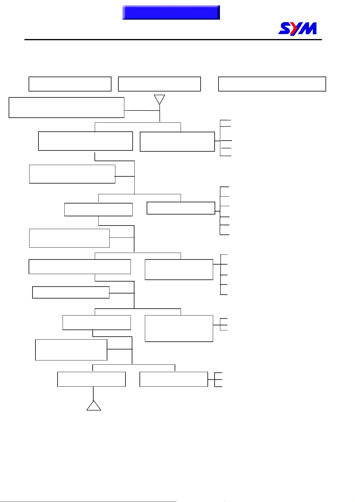
A. Engine cannot be started or difficult to be started
Check and adjustment Fault condition Probable causes
Press the fuel injector feed pipe and confirm
whether there is fuel in the feed pipe
1. Check the fuel amount in the fuel tank
2. Check if the fuel pipe and the vacuum
The fuel supply to the fuel injector is
sufficient
Check the spark plug ignition
condition
The fuel injector is not
supplied with sufficient fuel
tube are blocked or not
3. Malfunction of fuel pump relay or wiring
4. Malfunction of fuel pump
5. The fuel strainer is blocked or not
Sparks
Perform cylinder compression
ressure test
Normal cylinder compression pressure
Restart the engine
No ignition With signs of ignition but
Remove and check the
spark plug
Week sparks or no spark
Low or no compression
pressure
the engine cannot be
started
1. Malfunction of spark plug
2. Spark plug contamination
3. Malfunction of ECU
4. Malfunction of the AC Generator
5. Ignition coil is in open or short circuit
6. Malfunction of main switch
1. Piston ring seized
2. Malfunction of cylinder valves
3. Worn cylinder and piston ring
4. Cylinder gasket leakage
5. Sand hole in the com
1. Malfunction of throttle valve operation
2. Air sucked into intake manifold
3. Incorrect ignition timing
ression parts
1. Contaminated or clogged fuel injector
Dry spark plug Wet spark plug
1-16
2. Malfunction of throttle valve operation
3. Malfunction of fuel pressure regulator
Page 22
f
A
To this chapter contents
1. GENERAL INFORMATION
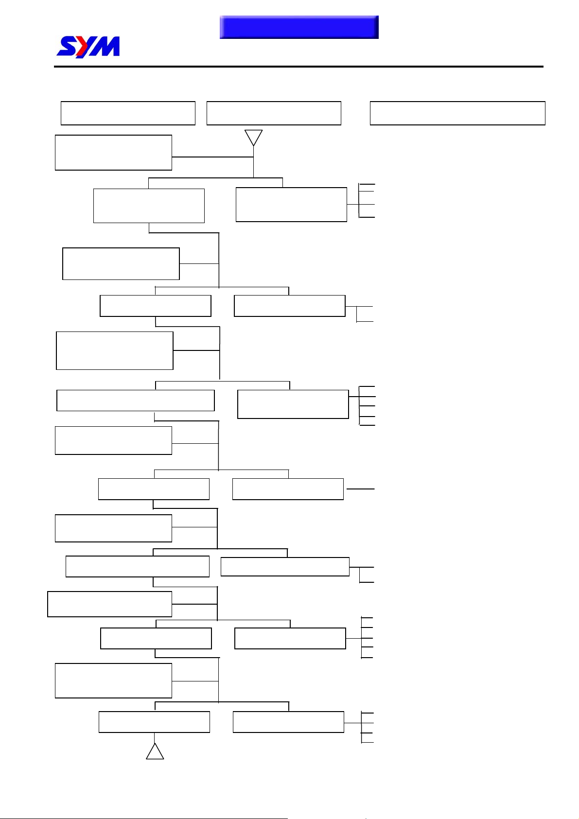
B. Engine runs sluggish (Speed does not pick up, lack of power)
Check and adjustment Fault condition Probable causes
Accelerate gradually and
check engine RPM
Engine RPM can be
increased
Engine RPM cannot be
increased
1. Clogged air cleaner
2. Poor fuel supply
3. Clogged exhaust pipe
4. Clogged
uel injector
Check ignition timing
(Using ignition lamp)
Correct ignition timing Incorrect ignition timing
Check cylinder compression
pressure (using compression
pressure gauge)
Normal compression pressure Abnormal compression
pressure
Check if the fuel injector is
clogged or not
Not clogged Clogged
Remove and check the
spark plug
No contamination or discoloration
Check if the engine is over
Contaminated or discolored
1. Malfunction of ECU
2. Malfunction of AC Generator
1. Worn out cylinder or piston ring
2. Cylinder gasket leakage
3. Sand hole in compression parts
4. Valve deterioration
5. Jammed piston ring
1. Replace the fuel injector
1. Remove the dirt
2. Incorrect spark plug heat range
1. Worn out piston or cylinder
Normal Engine overheated
Continually drive in
acceleration or high speed
No knocking Knocking
2. Abnormal fuel injector
3. Poor fuel quality
4. Carbon deposit in the combustion chamber
5. Abnormal ignition timing
1. Carbon deposit in the combustion chamber
2. Malfunction of fuel injector
3. Poor fuel quality
4.
bnormal ignition timing
1-17
Page 23
pply
gg
To this chapter contents
1. GENERAL INFORMATION
C. Engine runs sluggish (especially in low speed and idling)
Check for any air sucked in through
the throttle body insulator gasket
D. Engine runs sluggish (High speed)
Check and adjustment Fault condition Probable causes
Check ignition timing
(using ignition lamp)
Normal
No air sucked in
Remove the spark plug and
check the spark condition
Good spark Poor spark
Check and adjustment Fault condition Probable causes
Check ignition timing
Abnormal
Air sucked in
1. Incorrect ignition timing (malfunction of
ECU or AC Generator)
1. Abnormal throttle body insulator gasket.
2. Abnormal throttle body installation
3. Abnormal inlet pipe gasket
4. Damaged ABV pipe
1. Contaminated spark plug
2. Malfunction of ECU
3. Malfunction of AC Generator
4. Malfunction of ignition coil
5. Open or short circuit in spark plug
leads
6. Malfunction of main switch
Normal Abnormal
Check the fuel pump
su
condition
Good Poor
Check if fuel injector clogged
Normal Clogged
1. Malfunction of ECU
2. Malfunction of AC Generator
1. Insufficient fuel in the fuel tank
2. Pressed or clo
1. Replace the fuel injector
ed fuel pipe
1-18
Page 24
To this chapter contents
1. GENERAL INFORMATION
E. CLUTCH AND DRIVING PULLEY
FAULT CONDITION PROBABLE CAUSES
Engine can be started but the
vehicle cannot run
Engine shuts down or trembles
when the vehicle is running (rear
wheel rotates during engine idling).
1. Worn out or damaged drive belt
2. Damaged movable drive face
3. Damaged driven face spring
4. Broken clutch weight
5. Broken drive shaft groove
6. Worn out or damaged transmission gear
1. Broken clutch spring
2. Clutch outer stuck with clutch weights
3. Connection parts between clutch and shaft worn out or
burned
Poor initial driving (poor climbing
performance)
1. Worn or deformed drive belt
2. Worn weight roller
3. Worn driven face
4. Deformed driven face spring
5. Grease on drive belt or drive / driven face
1-19
Page 25
To this chapter contents
g
1. GENERAL INFORMATION
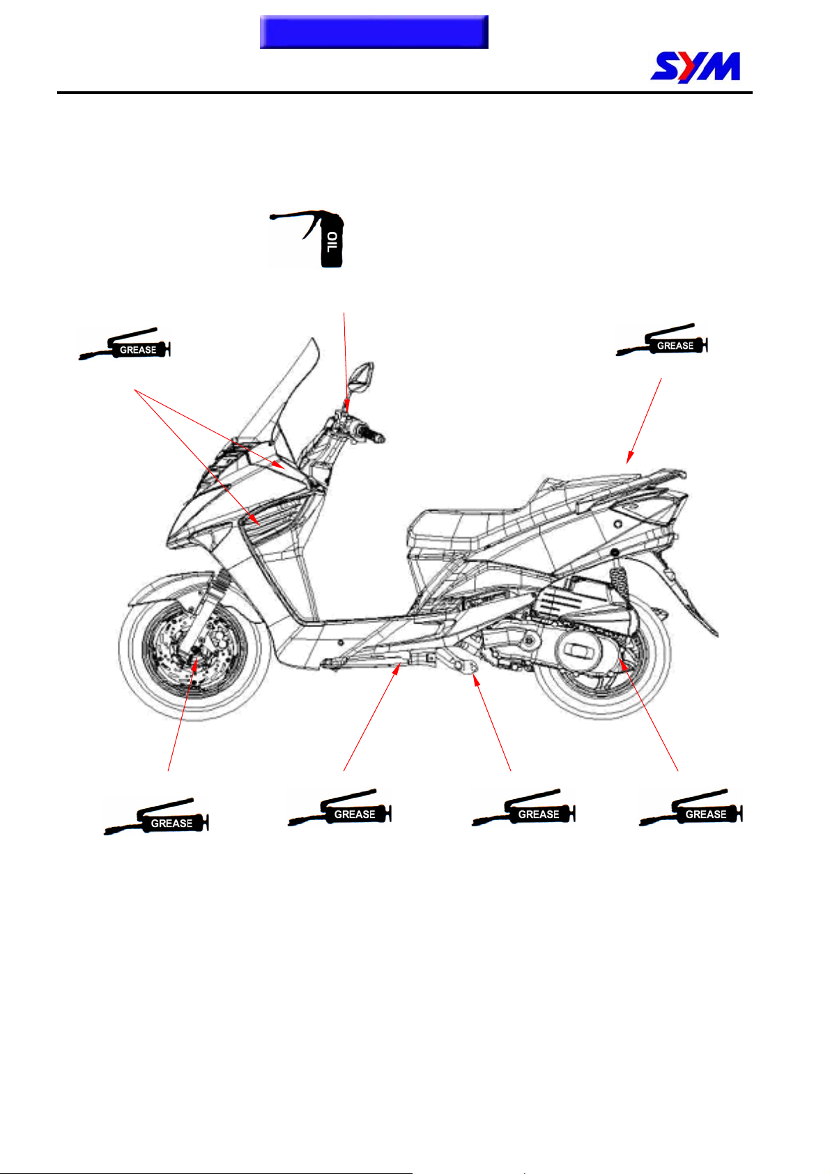
Lubrication Points
Steering stem
bearin
Throttle cable / front &
rear brake lever pivot
Seat catch
1-20
Front wheel bearing
Side stand pivot
Main stand pivot
Rear wheel bearing
Page 26
p
/
/
/
Homepage
Contents
2. Maintenance Information
Precautions in Operation..................2-1
Periodical Maintenance
Schedule ............................................2-2
Fuel Lines ..........................................2-3
Throttle Operation.............................2-3
Air Cleaner.........................................2-4
Spark Plug .........................................2-4
Valve Clearance.................................2-5
Ignition System..................................2-6
Cylinder Compression Pressure......2-7
Drive Belt ...........................................2-7
Brake System (front/rear
disk brake) .........................................2-8
Brake Hose ........................................2-8
Precautions in Operation
Brake Fluid ........................................ 2-8
Filling out brake fluid........................ 2-8
Air bleed operation........................... 2-9
Add brake fluid.................................. 2-9
Brake lining ....................................... 2-9
Brake light switch............................. 2-10
Headlight beam distance.................. 2-10
Clutch weight .................................... 2-10
Side Stand ......................................... 2-11
Front / Rear Cushion ........................ 2-11
Nut, bolts tightness. ......................... 2-11
Wheel / Tire........................................ 2-12
2
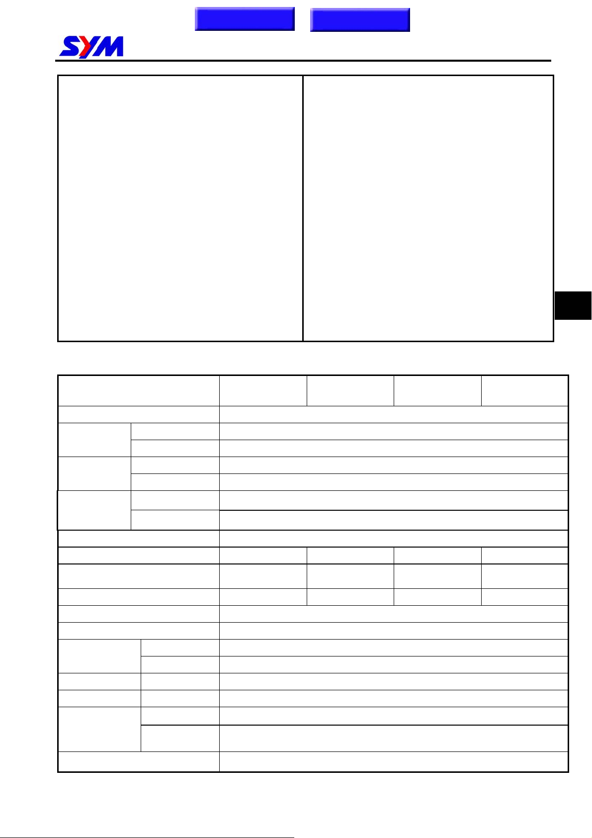
Model
Fuel Tank Capacity 7,600 c.c.
Engine Oil
Transmission
Gear oil
Capacity of
Clearance of throttle valve 2~6 mm
Spark plug CR7E CR7E CR8E CR7E
〝F〞Mark in idling speed
Full timing advanced BTDC 27º BTDC 24º BTDC 27º BTDC 24º
Idling speed 1,800±100 rpm
Cylinder compression pressure 12 ± 2 Kg/cm²
Valve
clearance
coolant
capacity 1,000 c.c.
change 800 c.c.
capacity 110 c.c.
change 100 c.c.
Engine + radiator 780 c.c.
Reservoir upper 420 c.c.
IN 0.12±0.02 mm
EX 0.12±0.02 mm
LF12W-6/F
BTDC 13º /
1800r
LF12W2-7
BTDC 10º
m
1800rpm
LF18W-A/W3-H
/W5-C
BTDC 13º
1800rpm
LF18W-6/W1-9
/W2-7/W4-8
BTDC 10º
1800rpm
Tire dimension Front 110/90-13 56P
Tire dimension Rear 130/70-12 64L
Tire pressure
(cold)
Battery 12V8Ah (MF battery) YTX9-BS / GTX9-BS
single Front: 1.75 Kg/cm² Rear: 2.25 Kg/cm²
Load 90 Kg
(full load)
Front: 1.75 Kg/cm² Rear: 2.5 Kg/cm²
2-1
Page 27
To this chapter contents
2. Maintenance Information
Periodical Maintenance Schedule
Mainte
nance
Code
item
Every
300KM
1 ☆Air cleaner I C C R C
2 ☆Fuel filter I I R
3 ☆Oil filter C C C
4 ☆Engine oil cha nge R Replacement for every 1000 km
5 Tire pressure I I I I I I
6 Battery inspection I I I I I I
7 Brake & free play check I I I I I I
8 Steering handle check I I I
9 Cushion op eration che ck I I I
10 Every screw tightening
I I I I I I
check
11 Gear oil check for leaking I I I I I I
12 ☆Spark plug check or change I I R R R
13 ☆Gear oil change R Replacement for every 5000 km
14 Frame lubrication L L
15 Exhaust pipe I I I I I I
16 ☆Ignition timing I I I I I I
17 ☆emission check in Idling A I I I I I
18 ☆Throttle operation I I I I I
19 ☆Engine bolt tightening I I I I I
20 ☆CVT driving device(belt) I R I
21 ☆CVT driving device(roller) C C C
22 Lights/electrical
I I I I I I
equipment/multi-meters
23 Main/side stands & springs I I I
24 Fuel lines I I I I I
25 Shock absorbers I I I I
26 Cam chain I I I I I
27 ☆Valve clearance I A A A A
28 Lines & connections in
I I I I I I
cooling system
29 Coolant reservoir I I I I I I
30 Coolant I Replacement for every 1 year
Code: I ~ Inspection, cleaning, and adjustment R ~ Replacement C ~ Cleaning (replaced if necessary) L ~
Lubrication
Have your motorcycle checked, adjusted, and recorded maintenance data periodically by your SYM Authorized Dealer to
maintain the motorcycle at the optimum condition
The above maintenance schedule is established by taking the monthly 1000 kilometers as a reference which ever comes
first.
Remarks: 1. These marks “ ☆” in the schedule are emission control items. According to EPA regulations, these items
must be performed normally perio dical ma inte nance foll owing the use r manua l instr ucti ons. They are
prohibited to be adjusted or re paired by una uthorize d pe ople . Otherwise, SYM is no responsible for the
charge.
2. Clean or replace the air cleaner element more often when the motorcycle is operated on dusty roads or in the
Heavily- polluted environment.
3. Maintenance should be performed more often if the motorcycle is frequentl y oper ated in high speed and after
the motorcycle has accumulated a higher mileage.
4. Preventive maintenance
a. Ignition system-Perform maintenance and check when continuous abnormal ignition, misfire, after-burn, overheating
occur.
b. Carbon deposit removal-Remove carbon deposits in cylinder head, piston heads, exhaust system when power is
obvious lower. Than ever
c. Replace worn out pistons, cylinder head.
1 Month
every
1000KM
3 month
every
3000KM
6 month
every
6000KM
1 year
every
12000KM
15 month
every
14500KM
2-2
Page 28
To this chapter contents
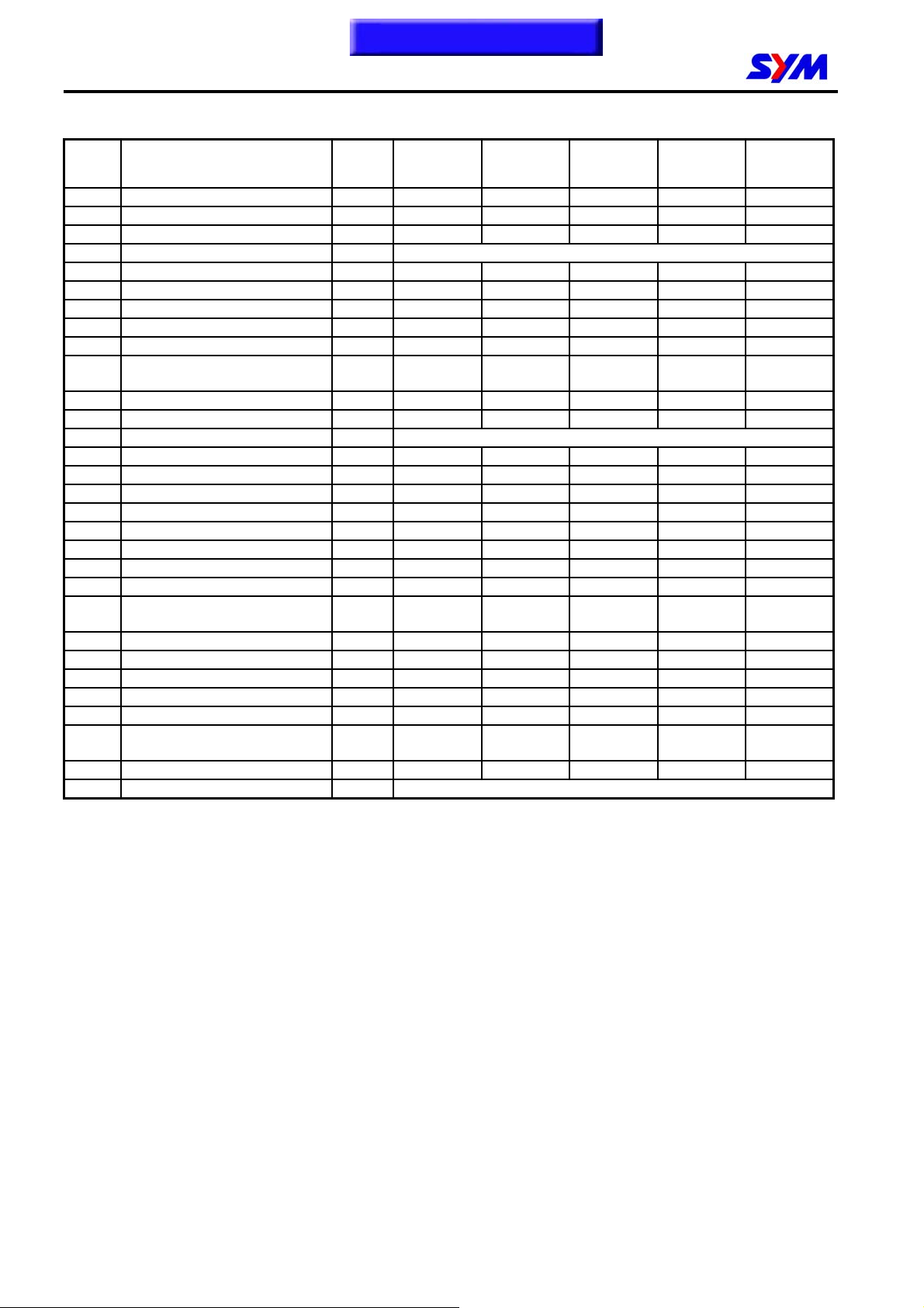
Fuel Lines
Remove trunk
Remove side cover.
Remove central cover.
Remove body frame cover.
Remove pedal.
Remove front glove box.
Check all lines, and replace it when they are
deterioration, damage or leaking.
Warning
Gasoline is a low ignition material so any
kind of fire is strictly prohibited as dealing it.
Throttle Operation
Have a wide open of throttle valve as handle bar
in any position and release it to let back original
(full closed) position.
Check handle bar if its operation is smooth.
Check acceleration cable and replace it if
deteriorated, twisted or damaged.
Lubricate the cable if operation is not smooth
Measure handle bar free play in its flange part.
Free play: 2~6 mm.
Adjustment can be done in either end.
Secondary adjustment is conducted from top
side.
Remove rubber boot, loosen fixing nut, and then
adjust it by turning the adjustment nut.
Primary adjustment is conducted from bottom
side.
Loosen fixing nut, and adjust by turning the
adjustment nut.
Tighten the fixing nut, and check acceleration
operation condition.
2. Maintenance Information
Fuel pump
Filler hole
Fuel tank
2~6 mm
2-3
Page 29
To this chapter contents
2. Maintenance Information
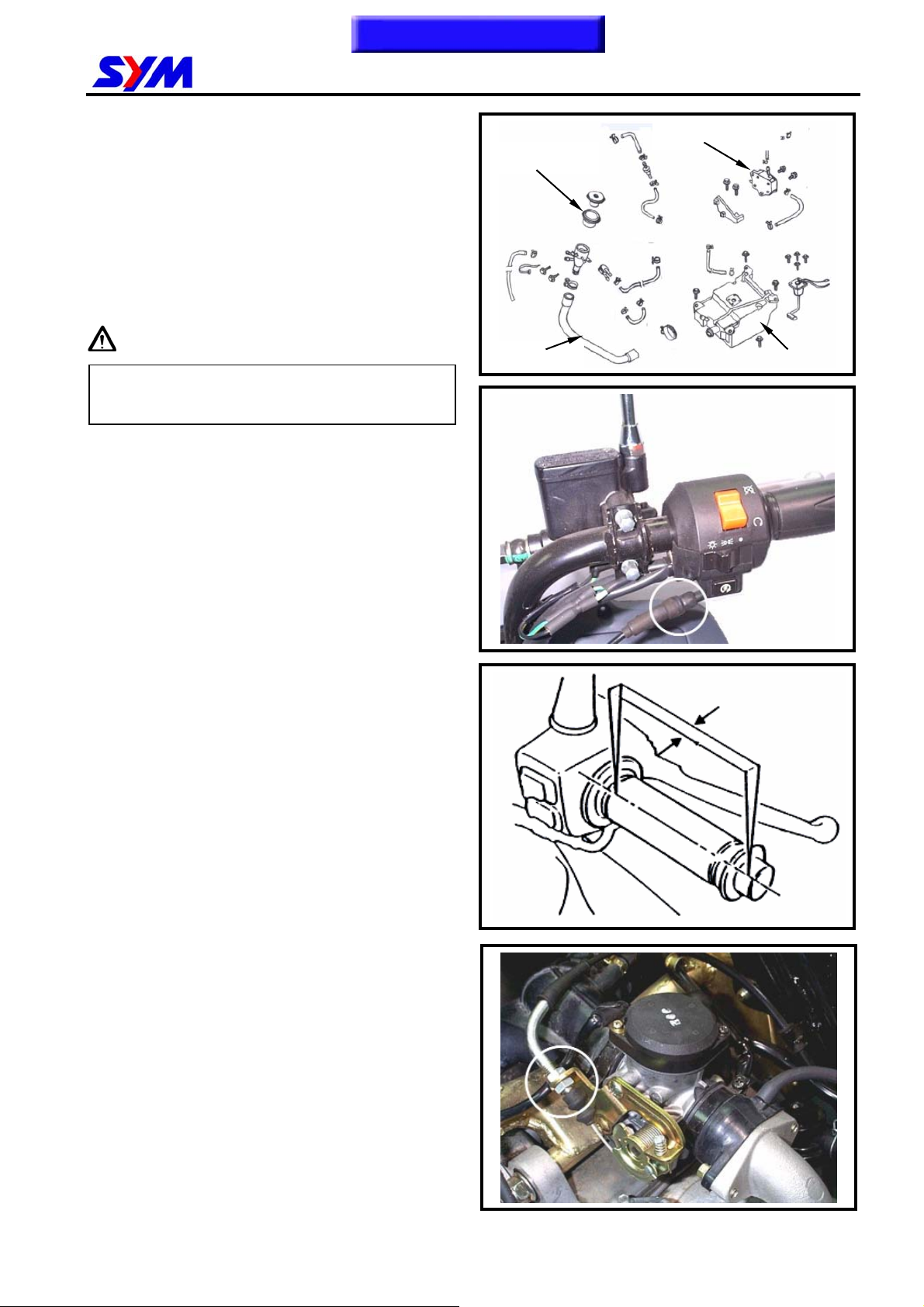
Air Cleaner
Remove trunk.
Remove side cover.
Remove 8 screws from the air cleaner cover and
then remove the cover.
Caution
Air cleaner element contains a paper made
filter so do not try to clean it.
Spark Plug
Recommended spark plug: CR7E / CR8E
Remove trunk.
Remove central cover.
Remove spark plug cap.
Clean dirt around the spark plug hole.
Remove spark plug.
Measure spark plug gap.
Spark plug gap:0.8 mm
Carefully bend ground electrode of the plug to
adjust the gap if necessary.
Hold spark plug washer and install the spark
plug by screwing it.
Tighten the plug by turning 1/2 turn more with
plug socket after installed.
Connect spark plug cap.
Ground electrode
Central electrode
0.8 mm
2-4
Page 30
To this chapter contents
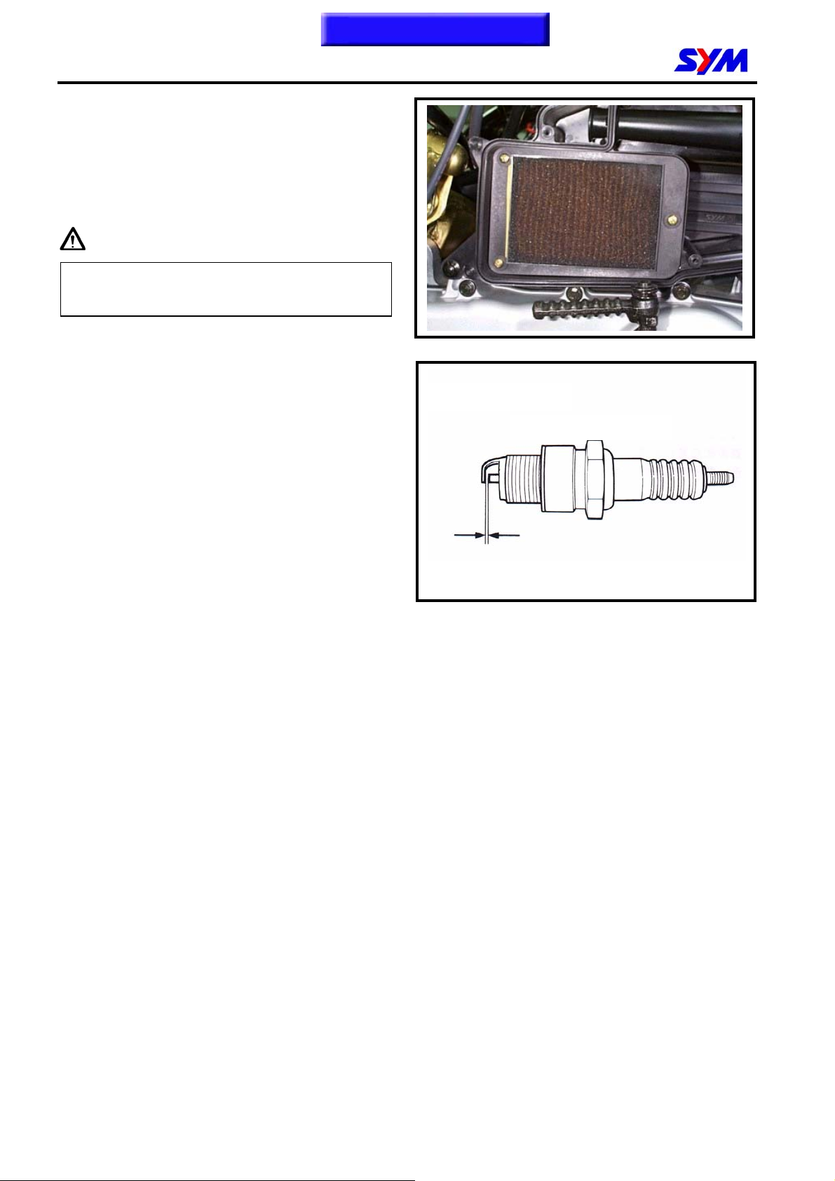
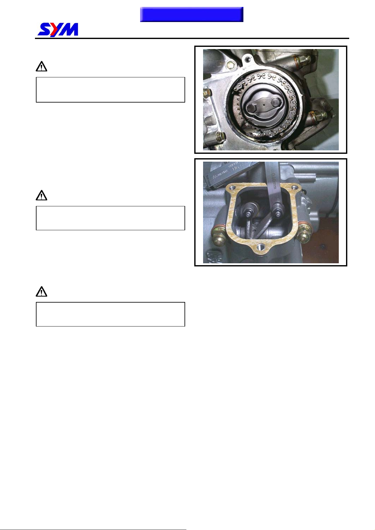
Valve Clearance
Caution
Checks and adjustment must be performed
when the engine temperature is below 35℃.
Remove trunk.
Remove central cover.
Remove valve adjustment cap.
Remove cylinder head side cover.
Turn camshaft bolt in C.W. direction and let the
“T” mark on the camshaft sprocket align with
cylinder head mark so that piston is placed at
TDC position in compression stroke.
2. Maintenance Information
Caution
Do not turn the bolt in C.C.W. direction to
prevent from camshaft bolt looseness.
Check & adjust valve clearance with feeler
gauge.
Valve clearance (IN/EX): 0.12 ± 0.02 mm
Loosen fixing nut and turn the adjustment nut for
adjustment.
Caution
Re-check the valve clearance after tightened
the fixing nut.
2-5
Page 31

To this chapter contents
2. Maintenance Information
Ignition System
Caution
Transistor ignition system is set by
manufacturer so it can not be adjusted.
Ignition timing check procedure is for
checking whether ECU function is in normal
or not.
Remove right side cover.
Remove ignition timing hole cap located in front
upper side of engine right cover.
Connect tachometer and ignition lamp.
Start engine.
As engine in idle speed: 1600 rpm, aim at the
mark “F” with the ignition lamp. Then, it means
that ignition timing is correct.
Increase engine speed to 6000 rpm to check
ignition advance degree. If indent is located
within the ignition advance degrees, it means
that the ignition advance degree is in normal.
If ignition timing is incorrect, check ECU, pulse
rotor and pulse generator. Replace it if
malfunction of these parts is found.
Ignition coil cable
2-6
Page 32

To this chapter contents
Cylinder Compression Pressure
Warm up the engine.
Turn off the engine.
Remove the trunk.
Remove the central cover.
Remove spark plug cap and spark plug.
Install compression gauge.
Full open the throttle valve, and rotate the
engine by means of starter motor.
Caution
Rotate the engine until the reading in the
gauge no more increasing.
Usually, the highest pressure reading will be
obtained in 4~7 seconds.
2. Maintenance Information
Compression pressure: 12 ± 2 Kg/cm²
Check following items if the pressure is too low:
․Incorrect valve clearance.
․Valve leaking.
․Cylinder head leaking, piston, piston ring and
cylinder worn out.
If the pressure is too high, it means carbon
deposits in combustion chamber or piston
head.
Drive Belt
Remove left side cover.
Remove mounting bolt located under air cleaner.
Remove 9 bolts of the engine left side cover and
the cover.
Check if the belt is crack or worn out.
Replace the belt if necessary or in accord with
the periodical maintenance schedule to replace
it.
Teeth
Width
2-7
Page 33

To this chapter contents
2. Maintenance Information
Brake System (FRONT/REAR DISK
BRAKE)
Free play of front/rear brake: 10~20 mm
Brake Hose
Make sure the brake hoses for corrosion or
leaking oil.
Brake Fluid
10~20mm
(3/8~3/4 in)
Brake hose
Check brake fluid level in the brake fluid
reservoir. If the level is lower than the LOWER
limit, add brake fluid to UPPER limit. Also check
brake system for leaking if low brake level found.
Caution
In order to maintain brake fluid in the
reservoir in horizontal position, do not
remove the cap until handle bar stop.
Do not operate the brake lever after the cap
had been removed. Otherwise, the brake
fluid will spread out if operated the lever.
Do not mix non-compatible brake fluid
together.
Filling Out Brake Fluid
Tighten the drain valve, and add brake fluid.
Operate the brake lever so that brake fluid
contents inside the brake system hoses.
LOWER
LOWER
Master cylinder
cap
Plate
diaphragm
Diaphragm
UPPER
2-8
Page 34

To this chapter contents
Air Bleed Operation
Connect a transparent hose to draining valve.
Hold the brake lever and open air bleeding valve.
Perform this operation alternative until there is
no air inside the brake system hoses.
Caution
Before closing the air bleed valve, do not
release the brake lever.
Add Brake Fluid
Add brake fluid to UPPER limit lever.
Recommended brake fluid: DOT3 or DOT4
WELL RUN brake fluid.
2. Maintenance Information
Air bubble
LOWER
Drain valve
Transparent hose
Master cylinder
cap
Plate
diaphragm
Diaphragm
UPPER
Caution
Never mix or use dirty brake fluid to prevent
from damage brake system or reducing
brake performance.
Brake Lining
The indent mark on brake lining is the wear
limitation.
Replace the brake lining if the wear limit mark
closed to the edge of brake disc.
Caution
It is not necessary to remove brake hose
when replacing the brake lining.
Remove the brake clipper bolt, and take out the
clipper.
Caution
Lining
Brake
caliper
Brake disk
Caliper
bolt
Do not operate the brake lever after the
clipper removed to avoid clipping the brake
lining.
Pry out the brake lining with a flat driver if lining
is clipped.
2-9
Page 35

y
Adj
To this chapter contents
2. Maintenance Information
Remove brake lining bolt.
Take out the lining.
Caution
In order to maintain brake power balance,
the brake lining must be replaced with one
set.
Brake Light Switch
The brake lamp switch is to light up brake lamp
as brake applied.
Make sure that electrical starter can be operated
only under brake applying.
Headlight Beam Distance
Lining
Lining bolt
Master
linder
c
Turn on main switch
Turn the headlight adjust screw with driver to
adjust headlight beam high.
Caution
To adjust the headlight beam follows related
regulations.
Warning
Improper headlight beam adjustment will
make in coming driver dazzled or insufficient
lighting.
Clutch Weight
Run the motorcycle and increase throttle valve
opening gradually to check clutch operation.
If the motorcycle is in forward moving and
shaking, check clutch disc condition. Replace it
if necessary.
Brake switch
ust screw
2-10
Page 36

To this chapter contents
Side Stand
Check side stand spring for damage or
looseness.
Press down side stand and pull it with spring
gauge. If gauge reading is over 2 kg, it means
that the spring capacity is in normal.
Check if side stand set is operated smoothly.
Make sure that side stand is no bending or
deformation.
Front / Rear Cushion
Warning
Do not ride the motorcycle with poor shock
absorber.
Looseness, wear or damage shock absorber
will make poor stability and drive-ability.
2. Maintenance Information
Side stand
Front Cushion
Press down the front shock absorber for several
times to check it operation.
Check if it is damage
Replace relative parts if damage found.
Tighten all nuts and bolts.
Rear Cushion
Press down the front shock absorber for several
times to check it operation.
Check if it is damage
Replace relative parts if damage found.
Park the vehicle with main stand.
Turn the rear wheel forcefully and check if
engine bracket bushing worn out
Replace the bushing if looseness found.
Tighten all nuts and bolts.
Nuts / Bolts Tightness
Perform periodical maintenance in accord with
the Periodical Maintenance Schedule
Check if all bolts and nuts on the frame are
tightened securely.
Check all fixing pins, snap rings, hose clamps,
and wire holders for security.
2-11
Page 37

To this chapter contents
2. Maintenance Information
Wheel / Tire
Caution
Tire pressure check should be done as cold
engine.
Check if tire surface is ticked with nails, stones
or other materials.
Appointed tire pressure
Tire size Front tire Rear tire
Tire
pressure as
cold engine
(Kg/cm²)
Check if front and rear tires’ pressure is in
normal.
Measure tire thread depth from tire central
surface.
Replace the tire if the depth is not come with
following specification:
Load for
under 90
Kg
Full
loaded
Front tire: 1.5 mm
Rear tire: 2.0 mm
1.75 2.25
1.75 2.5
2-12
Page 38

Homepage
Contents
3. LUBRICATION SYSTEM
Precautions in Operation..................3-2
Troubleshooting................................3-2
Engine Oil ..........................................3-3
Engine Oil Strainer Clean.................3-3
Oil Pump Removal.............................3-4
Press-In Lubrication
Oil Route
CON-ROD
Spray Lubrication
Press-In Lubrication
OIL STRAINER
Oil Pump Disassembly ..................... 3-4
Oil Pump Inspection......................... 3-5
Oil Pump Reassembly...................... 3-5
Oil Pump Installation........................ 3-6
Gear Oil.............................................. 3-7
VALVE ROCKER ARM
CAM SHAFT
Spray Lubrication
Oil Route
Rotate Direction
OIL PUMP
3
3-1
Page 39

To this chapter contents
3. LUBRICATION SYSTEM
Precautions in Operation
General Information
‧ This chapter contains maintenance operation for the engine oil pump and gear oil replacement.
Specifications
Engine oil quantity Disassembly: 1000 c.c.
Change: 800 c.c.
Gear oil Disassembly: 110 c.c.
Change: 100 c.c.
Oil Oil viscosity SEA 10W-30
(Recommended King serial oils)
Gear oil Gear oil viscosity SEA 85W-140
(Recommended SYM Hypoid
gear oils)
Items Standard (mm) Limit (mm)
Inner rotor clearance 0.15 0.20
SAE
Oil pump
Torque value oil strainer
Engine oil drain bolt
Gear oil drain plug 1.1~1.4 Kgf-m
Gear oil inspection bolt 1.1~1.4 Kgf-m
Oil pump connection bolt 0.8~1.2 Kgf-m
Clearance between outer rotor and body 0.15~0.20 0.25
Clearance between rotor side and body 0.04~0.09 0.12
1.3~1.7 Kgf-m
1.9~2.5kgf-m
Troubleshooting
Low engine oil level
.Oil leaking
.Valve guide or seat worn out
.Piston ring worn out
Low oil pressure
.Low engine oil level
.Clogged in oil strainer, circuits or pipes
.Oil pump damage
Dirty oil
.No oil change in periodical
.Cylinder head gasket damage
.Piston ring worn out
3-2
Page 40

p
To this chapter contents
3. LUBRICATION SYSTEM
Engine Oil
Turn off engine, and park the motorcycle in flat
surface with main stand.
Check oil level with oil dipstick
So not screw the dipstick into engine as
checking.
If oil level is nearly low level, fill out
recommended oil to upper level.
Caution
Drain oil as engine warmed up so that
makes sure oil can be drained smoothly and
com
Place a oil pan under the motorcycle, and
remove oil drain bolt.
After drained, make sure washer can be re-used.
Install oil drain bolt.
Torque value: 1.1~1.5 Kgf-m
Fill out engine oil (oil viscosity SEA 10W-30).
Recommended using King serial oil.
Engine oil capacity: 0.8L when replacing
Install dipstick, start the engine for running
several minutes.
Turn off engine, and check oil level again.
Check if engine oil leaks.
letely.
Engine Oil Strainer Clean
Drain engine oil out.
Remove oil strainer and spring.
Clean oil strainer.
Check if O-ring can be re-used.
Install oil strainer and spring.
Install oil strainer cap.
Torque value: 1.3~1.7 Kgf-m
Add oil to crankcase (oil viscosity SAE 10W-30)
Recommended using King serial oil.
Drain bolt
3-3
Page 41

To this chapter contents
3. LUBRICATION SYSTEM
Oil Pump Removal
Remove generator and starting gear.
Remove snap ring and take out oil pump driving
chain and sprocket.
Torque value: 0.8~1.2 Kg-m
Make sure that pump shaft can be rotated freely.
Remove 2 bolts on the oil pump, and then
remove oil pump.
Oil Pump Disassembly
Remove the screws on oil pump cover and
disassemble the pump as illustration shown.
BOLT×2
3-4
Page 42

To this chapter contents
3. LUBRICATION SYSTEM
Oil Pump Inspection
Check the clearance between oil pump body
and outer rotor.
Limit: 0.25 mm
Check clearance between inner and outer
rotors.
Limit: 0.20 mm
Check clearance between rotor side face and
pump body
Limit: 0.12 mm
Oil Pump Reassembly
Install inner and outer rotors into the pump body
Align the indent on driving shaft with that of inner
rotor. Install the driving shaft
Install fixing pin
PIN
3-5
Page 43

To this chapter contents
3. LUBRICATION SYSTEM
Install the oil pump cover and fixing pin properly
Tighten screw
Make sure that oil pump shaft can be rotated
freely.
Oil Pump Installation
Install the oil pump, and then tighten bolts.
Torque value: 0.8~1.2 Kg-m
Make sure that oil pump shaft can be rotated
freely.
Install oil pump driving chain and sprocket, and
then install snap ring onto oil pump shaft.
Install starting gear and generator.
3-6
SCREW×1
Page 44

plug
To this chapter contents
3. LUBRICATION SYSTEM
Gear Oil
Oil level inspection
Park the motorcycle on flat surface with main
stand.
Turn off engine and remove oil inspection bolt.
Gear lubrication oil quantity has to be measured
with measure device.
If oil level is too low, add gear oil.
Recommended using King serial oils.
Install oil inspection bolt.
Torque value: 1.0~1.4 Kgf-m
Gear Oil Change
Remove oil level inspection bolt.
Remove drain plug and drain oil out.
Install the drain plug after drained.
Torque value: 1.0~1.4 Kgf-m
Make sure that the drain plug washer can be
re-used.
Add oil to specified quantity from the inspection
hole.
Gear Oil Quantity: 100 c.c. when replacing
Make sure that the bolt washer can be re-used,
and install the bolt.
Start engine and run engine for 2-3 minutes.
Turn off engine and make sure that oil level is in
correct level.
Make sure that no oil leaking.
Gear oil Inspection Bolt
Gear oil
drain
3-7
Page 45

To this chapter contents
3. LUBRICATION SYSTEM
NOTES:
3-8
Page 46

Homepage
Contents
Precautions in operation.....................4-2
Trouble diagnosis................................4-3
Air cut-off valve....................................4-4
Auto by-starter .....................................4-5
Carburetor removal..............................4-6
Vacuum chamber.................................4-6
4. FUEL SYSTEM
Float chamber..................................4-8
Installation of carburetor ................4-9
Adjustment of pilot screw...............4-10
Fuel tank .........................................4-11
Air cleaner........................................4-12
Carburetor
4
Fuel tank cap
Fuel pump
Fuel unit
Fuel tank
4-1
Page 47

To this chapter contents
4. FUEL SYSTEM
PRECAUTIONS IN OPERATION
General Information
Warning
Gasoline is a low ignition point and explosive materials, so always work in a well-ventilated place and
strictly prohibit flame when working with gasoline.
Cautions
․Do not bend off throttle cable. Damaged throttle cable will make unstable drive-ability.
․When disassembling fuel system parts, pay attention to O-ring position, replace with new one as
re-assembly
․There is a drain screw in the float chamber for draining residual gasoline.
‧Do not disassemble auto by-starter and air cut valve arbitrarily.
Specification
Item
Carburetor diameter 24 mm 25 mm
I.D. number CVK039 CVK066
Fuel level 20.5 mm 20.5 mm
Main injector #105 #108
Idle injector #35 #35
Idle speed 1600±100 rpm 1600±100 rpm
Throttle handle clearance 2~6 mm 2~6 mm
Pilot screw 2 1/4 turns 1 1/2 turns
LF12W-6/F LF18W-A/W3-H/W5-C
Torque value
Fuel valve tightening nut: 1.5~2.0Kgf-m
Tool
Special service tools
Vacuum/air pressure pump
General service tool
Fuel level gauge
4-2
Page 48

To this chapter contents
TROUBLE DIAGNOSIS
Poor engine start
z No fuel in fuel tank
z Clogged fuel tube
z Too much fuel in cylinder
z No spark from spark plug(malfunction of ignition system)
z Clogged air cleaner
z Malfunction of auto by-starter
z Malfunction of throttle operation
z Malfunction of purge control valve
Stall after started
z Malfunction of auto by-starter
z Incorrect ignition timing
z Malfunction of carburetor
z Dirty engine oil
z Air existing in intake system
z Incorrect idle speed
z Malfunction of purge control valve
Rough idle
z Malfunction of ignition system
z Incorrect idle speed
z Malfunction of carburetor
z Dirty fuel
Intermittently misfire as acceleration
z Malfunction of ignition system
Late ignition timing
z Malfunction of ignition system
z Malfunction of carburetor
Power insufficiency and fuel consuming
z Fuel system clogged
z Malfunction of ignition system
4. FUEL SYSTEM
Mixture too lean
z Clogged fuel injector
z Vacuum piston stick and closed
z Malfunction of float valve
z Fuel level too low in float chamber
z Clogged fuel tank cap vent
z Clogged fuel filter
z Obstructed fuel pipe
z Clogged air vent hose
z Air existing in intake system
Mixture too rich
z Clogged air injector
z Malfunction of float valve
z Fuel level too high in float chamber
z Malfunction of auto by-starter
z Dirty air cleaner
4-3
Page 49

To this chapter contents
4. FUEL SYSTEM
AIR CUT-OFF VALVE
Inspection
Disconnect vacuum hose and air vent hose from
the air cut-off valve.
Connect a hose from vacuum hose connector to
vacuum pump.
Connect air pump to air vent hose.
Apply with specified vacuum to air cut-off valve.
Vacuum value: 420~500 mm-Hg
Pump compressed air from air pump to air vent
hose.
Caution
The vacuum can not be over 600 mm-Hg. Or
the air cut-off will be damaged.
If the valve is in normal, it will restrict air-flow.
f air-flow is no restrict, replace carburetor
assembly.
4-4
Page 50

To this chapter contents
AUTO BY-STARTER
Inspection
Turn off engine and waiting for over 10 minutes
for cooling.
Check resistance across the two terminals of the
auto by-starter.
Resistance value: Max. 10Ω (Measured after
engine stopped for more than 10 minutes)
Replace the auto starter with a new one if
resistance value exceeds standard.
Remove carburetor, allow it to cool off for 30
minutes.
Connect a pressure tester from air pump.
Connect by-starter circuit.
Pump compressed air to the circuit.
Replace the auto by-starter if the circuit clogged.
Connect battery posts (12V) to starter’s
connectors. After 5 minutes, test the by-starter
circuit with compressed air. If air flows through
the circuit, then, replace the starter.
Removal
Remove fixing plate screw, and then remove the
plate and auto by-starter from carburetor.
Valve inspection
Check if auto by-starter and valve needle for
damage or wear out.
Installation
Install auto by-starter to the bottom of carburetor
body.
Install fixing plate to the upper groove of auto
by-starter, and install its flat surface to carburetor.
Install screw and tighten it.
Screw ×1
Screw ×1
Plate
4. FUEL SYSTEM
Auto by– starter
Needle
Vacuum tube
4-5
Page 51

To this chapter contents
4. FUEL SYSTEM
Carburetor removal
Remove the luggage box.
Loosen the adjustment nut and fixing nut of
throttle valve cable, and release the cable from
carburetor.
Remove air cut-off valve hose.
Remove fuel pipe, vacuum hose.
Disconnect automatic by-starter connectors.
Release the clamp strip of carburetor isolation.
Release the clamp strip of air cleaner.
Vacuum chamber
Removal
Loosen drain screw, and drain out residual fuel in
float chamber.
Remove 2 screws of vacuum chamber cover and
the cover.
Remove compress spring and vacuum piston.
Check if the vacuum piston for wear out, crack or
other damage.
Check if the diaphragm for damage or crack.
Auto by-starter
Throttle cable
Air cleaner clamp
Screw ×2 Spring
4-6
Page 52

To this chapter contents
Installation
Install needle, spring and needle seat to vacuum
piston.
Install vacuum piston to carburetor body and
align the indent on the diaphragm.
Install compress spring.
Install vacuum chamber cover and tighten 2
screws.
Piston
Needle
4. FUEL SYSTEM
Needle seat
Spring
Screw ×2
Caution
․Do not damage vacuum diaphragm.
․When tightening the vacuum chamber screw,
hold down vacuum piston.
4-7
Page 53

To this chapter contents
4. FUEL SYSTEM
FLOAT CHAMBER
Disassembly
Remove 4 mounting screws and remove float
chamber cover.
Remove the float pin and float.
Checking
Check float valve and valve seat for damage,
blocking.
Check float valve for wearing, and check valve
seat face for wear, dirt.
Float
Screw ×3
Caution
In case of worn out or dirt, the float valve and
valve seat will not tightly close causing fuel level
to increase and as a result, fuel flooding. A worn
out or dirty float valve must be replaced with a
new a new one.
Remove main jet, fuel needle jet holder, needle
jet, slow jet, pilot screw.
Caution
․Take care not to damage jets and adjust
screw.
․Before removing adjustment screw, turn it all
the way down and note the number of turns.
․Do not turn adjust screw forcefully to avoid
damaging valve seat face.
Clean jets with cleaning fluid. Then use
compressed air to blow the dirt off.
Blow carburetor body passages with compressed
air.
Float
Needle jet
holder
Pin
Needle jet
Screw ×1
Float valve
Caution
Remove vacuum chamber and air cut-off valve
as a set.
4-8
Main jet
Slow jet
Page 54

To this chapter contents
Assembly
Install main jet, fuel needle jet holder, fuel needle
jet slow jet and pilot screw.
Caution
Set the pilot screw in according to number of
turns noted before it was removed.
Install the float valve, float, and float pin.
Checking fuel level
Caution
• Check again to ensure float valve, float for
proper installation.
• To ensure correct measurement, position the
float meter in such a way so that float
chamber face is vertical to the main jet.
4. FUEL SYSTEM
Pilot screw
Fuel level: 20.5 mm
Installation of carburetor
Install carburetor in the reverse order of removal.
Following adjustments must be made after
installation.
․Throttle cable adjustment.
․Idle adjustment
Float gauge
4-9
Page 55

To this chapter contents
4. FUEL SYSTEM
Adjustment of pilot screw
Caution
․Pilot screw was set at factory, so no
adjustment is needed. Note the number of
turns it takes to screw it all the way in for ease
of installation.
․The main stand must be used to support the
motorcycle to perform the adjustments.
Use a tachometer when adjusting engine RPM.
Screw in adjustment screw gently, then back up to
standard turns.
Standard turns:
LA12W : 2 ± 1/4 turns
LA15W : 2 ± 1/2 turns
LA18W : 1 ± 1/2 turns
Throttle cable adjust nut 帽
Idle adjustment screw
Pilot screw
Caution
Do not screw in forceful to avoid damaging
screw seat face.
Warm up engine, adjust the stopper screw of
throttle valve to standard RPM.
Idle speed rpm: 1600 ± 100 rpm
Connect the hose of exhaust analyzer to exhaust
front end. Press test key on the analyzer.
Adjust the pilot screw and read CO reading on the
analyzer
CO standard value: 1.0~1.5 %
Accelerate in gradual increments, make sure rpm
and CO value are in standard value after engine
running in stable. If rpm and CO value fluctuated,
repeat the procedures described above for
adjusting to standard value.
4-10
Page 56

To this chapter contents
FUEL TANK
Fuel unit removal
Open the seat.
Remove the luggage box (6 bolts and 1 screw).
Remove rear carrier (3 bolts).
Remove rear bracket (2 bolts).
Remove the rear central cover (4 screws).
Remove the left and right pedals (1 bolt).
Remove the left and right covers (4 bolts).
Remove the central cover (6 screws).
Remove the left & right body covers and the
central upper cover (4 screws and 2 bolts).
Remove pedal (4 bolts and 4 screws).
Disconnect fuel unit connector.
Remove fuel unit (4 screws).
Caution
․Do not bend the float arm of fuel unit
.
․Do not fill out too much fuel to fuel tank.
4. FUEL SYSTEM
Fuel unit inspection (Refer to electrical equipment
17-15).
Fuel unit installation
Install the gauge in the reverse order of removal.
Caution
Do not forget to install the gasket of fuel unit or
damage it.
Fuel tank removal
Open the seat.
Remove the luggage box (6 bolts and 1 screw).
Remove the rear central cover (4 screws).
Remove the left and right pedals (1 bolt).
Remove the left and right covers (4 bolts).
Remove the central cover (6 screws).
Remove pedal (4 bolts and 4 screws).
Disconnect fuel unit connector.
Remove fuel unit (4 screws).
Remove fuel pump (2 bolts).
Remove fuel tank bracket (4 bolts).
Remove vacuum tube and fuel filter.
Remove fuel tank
Installation
Install the tank in the reverse order of removal.
4-11
Page 57

To this chapter contents
4. FUEL SYSTEM
AIR CLEANER
Open the seat.
Loosen the clamp strip of air cleaner.
Remove left cover (2 screws).
Remove mounting bolts for crankcase and gear
box (2 bolts).
Remove air cleaner cap (8 screws).
Remove air cleaner set (4 screws).
Caution
The air cleaner element is made of paper so do
not soap it into water or wash it with water.
Screw ×8
Element
4-12
Page 58

Homepage
Contents
5
EFi System Diagram······························5-1
EFi System Introduction························5-2
EFi System Components·······················5-3
EFi System Location ····························· 5-4
EFi System Component Description···· 5-5
EFi System Circuit·································5-8
Precautions in Operation······················ 5-9
Troubleshooting ···································· 5-10
Throttle Body & By-pass Valve Clean
Procedure··············································· 5-14
Fuel Lines··············································· 5-15
Ignition System······································5-16
EFi System Diagram
. Fuel Injection System
Crankshaft Position Sensor··················5-17
Engine Temperature Sensor / T-Map Sensor
·································································5-18
Air By-pass Valve···································5-19
Fuel Injector············································5-19
Fuel Pump···············································5-19
Fuel Unit··················································5-20
Fuel Tank················································5-23
Air Cleaner··············································5-24
EFi Troubleshooting & Solution ···········5-25
EFi Components Malfunction Check &
Replacement Procedure························5-53
5
5-1
Page 59

To this chapter contents
5. Fuel Injection System
EFi System Introduction
Based on 4-stroke SOHC engine, displacement 180 c.c. electronically controlled fuel injection.
The O2 sensor enhances the efficiency of the catalytic converter, by dynamically controlling the
Fuel/Air ratio.
Electronic Fuel Injection Device
Fuel supply devices: fuel tank, fuel pump, fuel filter, and fuel pressure regulator.
Fuel control devices: fuel injector, and ECU.
The fuel is pumped from electrical fuel pump in the fuel tank, to the injector on the inlet pipe.
The fuel pressure regulator keeps the pressure around 2.5 Bar. The signals from ECU enable the
injector to spray fuel into the combustion chamber once each two crankshaft-revolutions. The
excessive fuel flows back to the fuel tank through the fuel pressure regulator. Fuel pump is
placed inside the fuel tank to reduce the working noise, and the complicity of fuel pipes.
Electrically controlled ignition and injection system effectively reduce fuel consumption rate and
pollution.
In traditional gasoline engine, carburetor supplies the fuel. The process is done by the engine
vacuum, and the negative pressure in the carburetor mixes fuel with air. Under this condition,
three major processes are done simultaneously in the carburetor: 1. air quantity measurement,
the determination of fuel quantity, the mix of fuel and air.
Electronic fuel injection system separates the three major processes into three different devices:
1. T-MAP sensor measures the air quantity and temperature and sends the signal to ECU as a
reference. 2. ECU determines the amount of fuel to be injected, according to the default A/F rate.
3. ECU enables the injector to spray appropriate fuel amount. The independence of these three
functions will raise the accuracy of the whole process.
EFi engine uses computer-programmed fuel injection, the main features are:
1. The quantity of fuel injected is determined according to the condition of the engine. The engine
RPM, and throttle position determines the fuel quantity and injection time-length.
2. The quantity of fuel injection, and the determination of injection time length, are all controlled
by 16-bit microcomputer.
3. The fuel pressure regulator maintains a 2.5 Bar pressure difference between inlet pipe and fuel
pipe, raising the accuracy of fuel injection.
4. By measuring the air pressure of inlet pipe, this system gives the vehicle better
accommodation to the environment.
5. Air by-pass system supplies fuel and air to stabilize the idle running, and cold starting.
5-2
Page 60

To this chapter contents
5
EFi System Components
ECT Sensor
Battery
5V 12V
ECU
Integrated with T-MAP Sensor,
TPS, ABV, and Throttle Body
Main Switch
. Fuel Injection System
Fuel Pump
Ignition Coil
CPS
Fuel Injector
5-3
Page 61

To this chapter contents
5. Fuel Injection System
EFi System Location
Injector
Ignition Coil
ECU
Fuel Pump
ECT Sensor
CPS
5-4
Fuel Pump Relay
Page 62

To this chapter contents
5
EFi System Component Description
Integrated ECU Module
Engine Control Unit (ECU)
• Powered by DC 8~16V, and has 32 terminals connector on the unit.
• The hardware component consists of an 16-bit computer that is its
control center. It contains the functional circuit interface of engine
condition sensing and the driving actuator for the air by-pass valve,
fuel injector, and fuel pump, as well as transistor ignition coil.
• Its major software is a monitor strategy operation program that
includes with controlling strategy, microarray profile and
self-diagnosis programs.
Air Bypass Valve (ABV)
• Its major component is the solenoid valve of high resistance driven
by electric current.
• By means of signals from all sensors, ECU outputs a signal to
control the opening angle of the valve so that can adjust air flowing
to the inlet manifold through the air by-pass valve, and then correct
the idle speed to have engine in normal operation.
T-MAP Sensor
• The major component of the T-MAP sensor is a variable transistor IC.
Its reference voltage is DC 5V, and output voltage range is DC 0~5V.
• It is a sensor of combination by both sensing pressure and
temperature, and can measure the absolute pressure and
temperature in intake process. It also conducts the fuel injection
quantity correction based on environmental temperature and position
level.
Throttle Position Sensor (TPS)
• Its major component is a highly variable resistor. The input voltage
range: 5V DC.
• Located on the side of throttle body. By means of the throttle valve
rotation to cause voltage change in linear, it provides ECU with
current throttle valve openness information. And also, the ECU
determines the most properly fuel injection and ignition timing.
. Fuel Injection System
5-5
Page 63

To this chapter contents
5. Fuel Injection System
Fuel Injector
• Powered by DC 8~16V, and has 2 terminals connector on the
• Its major component is the solenoid valve of high resistance driven
• The two terminals are connected to power source and ground
Fuel Pump
• Powered by DC 8~16V, and has 2 terminals connector on the pump.
• The two terminals are connected to power source and ground
• Its major component is a driving fan pump that equipped with a low
• The fuel pump is located inside of the fuel tank, and installed a filter
injector.
by electronic current.
respective. It is controlled by ECU to determine the injection timing,
and the injector pulse width. Working with 4-valve engine, the unique
2-hole designed injector can provide each intake valve with suitable
fuel quantity to reduce HC emission.
respective. The ECU is to control and manage the operation of fuel
pump through electrical power.
electrical consuming DC motor. Powered by 12V voltage and keep
fuel pressure inside the fuel pump in 2.5 bars, which can offer 14
liters of fuel per hour.
in front of its inlet so that can prevent from foreign materials sucking
into the fuel pump to damage it and the fuel injector.
Ignition Coil
• Powered by DC 8~16V, and has 2 terminals connector on the coil.
• The two terminals are connected to power source and ground
respective. Its major component is the high transferring rate
transformer.
• Its ignition timing is controlled by computer program. From the
signals of crankshaft position sensor, throttle position sensor, and
engine temperature sensor as well as intake air temperature sensor,
and correspondence with engine speed, then the ECU determines
the ignition timing properly by means of controlling primary current in
ON & OFF operation to create the secondary voltage of
25000~30000V. And then, the voltage triggers the spark plug ignition.
Such kind of ignition system not only can enhance engine
performance to maximum, but also increases fuel consumption
efficiency and improves emission quality.
5-6
Page 64

To this chapter contents
5
ECT Sensor
CPS
. Fuel Injection System
• Powered by 5V DC from ECU, and has 2 terminals connector on the
sensor. One terminal is for voltage output and the other one for
ground.
• Its major component is the thermo-resistance of negative
temperature coefficient (temperature rises up while resistance falls
down).
• Located on the cylinder head. Correspondence with engine coolant
temperature change, it transferred to voltage signal and sent to ECU
to calculate current temperature. Then, the ECU will correct fuel
injection time and ignition timing according to engine warm up
condition.
• It does not need power supply, and has 2-signal terminals connector
on the sensor.
• Its major component is the magnetic pickup coil, and its output
voltage range is ±0.8~100V.
• The air gap between the sensor and flywheel must have .07~1.1mm.
• By cutting the magnetic field, the magnetic sensor sends an
inductive voltage that is created with the rotation gear (24-1 tooth) on
the flywheel, and the pulse will be sent to the ECU. Then, the ECU
calculates current engine speed and crank position based on the
voltage so that controls fuel injection quantity and ignition timing
properly.
O2 Sensor
• Powered by DC 8~16V, and has 4 terminals connector on the sensor.
The first terminal is for power input; the second is for heating coil.
The third is for ground, and the last is for signal output.
• The O2 sensor feeds signal to ECU, and the ECU can control the
air/fuel rate around 14.6. It’s a close –loop control system.
• The catalytic converter reaches the best converting rate when this
14.6 A/F ratio is maintained.
• The heating coil resistance <200kohm (30—45kohm)
5-7
Page 65

To this chapter contents
5. Fuel Injection System
EFi System Circuit
5-8
Page 66

To this chapter contents
5
. Fuel Injection System
Precautions in Operation
General information
Warning
● Gasoline is a low ignition point and explosive materials, so always work in a well-ventilated
place and strictly prohibit flame when working with gasoline.
● Release the fuel pressure before removing the fuel pipe to prevent splashing the fuel.
Caution
● Do not bend or twist throttle cable. Damaged cable will make unstable drive ability.
● When disassembling the fuel system parts, pay attention to O-ring position, replace with new
one as re-assembly.
Fuel pressure release procedure:
Disconnect the fuel pump relay, switch on and press the start switch for a few seconds to crank
the engine.
Specification
Item
Idle speed 1800±100 rpm
Throttle grip free play 2~6 mm
Fuel pressure 2.5 bar
Torque value
Engine temperature sensor:0.74~0.88 kgf-m
O2 sensor:3.6~4.6 kgf-m
Special tools
Injection system diagnostic tool
Fuel pressure gauge SYM-HT07010
5-9
Page 67

To this chapter contents
5. Fuel Injection System
Troubleshooting
EFi circuit inspection
Does the warning lamp goes on for 2 seconds and
then off?
Is battery voltage over 12.5V?
The voltage difference between battery and ECU is
less than 0.2V.
1. Turn off the main switch.
2. Disconnect the ECU connector.
3. Turn on the main switch.
4. With a multi-meter to measure the voltage
between the F4 pin(+) and the H4 pin (-).
Make sure the voltage difference between
battery and ECU is less than 0.2V.
The voltage difference between battery and active
components is less than 0.2V.
1. Turn off the ignition switch.
2. Disconnect the connectors of the fuel injector,
by-pass valve, and ignition coil.
3. Measure the voltage between battery negative
side and the each connector (1).
4. Make sure the voltage difference between
battery and those active components is less
than 0.2V.
The voltage difference between 5V-sensors is less
than 0.2V.
1. Turn off the ignition switch.
2. Disconnect the connectors of throttle valve
position sensor and intake manifold
temperature/pressure sensors.
3. Turn on the ignition switch.
4. Measure the voltage between the pins(1)(4) of
throttle valve position, and the pins of intake
manifold temperature/pressure sensors (1) (3) is
within 5V±0.2V.
The voltage difference between battery and fuel
pump is less than 0.2V.
1. Turn off the ignition switch.
2. Disconnect the fuel pump connector.
3. With the probes of multi-meter to touch the
positive & negative sides of the fuel pump.
4. Turn on the ignition switch.
5. Record the voltage difference of the fuel pump
within 3 seconds.
6. Make sure the voltage difference between
battery and fuel pump is less than 0.2V.
Switch on
OK
OK
OK
OK
OK
OK
END
NG
NG
NG
NG
NG
NG
1. Burnt Bulb?
2. Blown fuse?
3. Battery voltage too low?
4. Poor wire contact on ECU
circuit?
5. Poor contact on the master
switch?
6. Malfunction of ECU?
1. Abnormal charging circuit?
2. Battery cannot be charged?
1. Abnormal wire connection?
1. Abnormal wire connection?
1. Abnormal wire connection?
2. Malfunction of ECU?
1. Abnormal wire connection?
2. Malfunction of relay?
3. Malfunction of ECU?
5-10
Page 68

p
To this chapter contents
5
Engine cannot be started or difficult to start.
Does the warning lamp goes
on for 2 seconds and then off?
Is the warning lamp out of
order?
Is the electrical circuit abnormal?
Is the fuel system abnormal?
Is the engine abnormal?
Cannot be started or difficult to start
NG
OK
NG
OK
NG
OK
NG
OK
NG
OK
END
. Fuel Injection System
1. Check electrical circuit according to
procedure.
1. Connect the diagnostic tool and check
trouble content.
2. Trouble shooting according to the
troubleshooting procedure.
1. No spark on the spark plug?
2. Wet spark plug?
3. Loosen spark plug cap?
4. Short in RPM sensor?
5. Loosen high voltage cable?
6. No connection for the by-pass valve?
7. Abnormal ECU?
8. Clean the throttle valve body and ECU
does not be set-u
1. Low fuel in fuel tank.
2. The fuel pressure of the injector is lower
than 2.5bar.
3. Fuel leaking in pipe?
4. Abnormal regulator?
5. Fuel pump pipe leaking?
6. Abnormal fuel pump?
7. Abnormal fuel injector?
1. No valve clearance?
2. Incorrect ignition timing?
3. Stuck valve?
4. Worn out cylinder and piston ring?
5. Improperly adjustment of the air
adjustment screw onto the throttle valve
body?
?
5-11
Page 69

To this chapter contents
5. Fuel Injection System
Diagnosis of Idle Speed Misfire
Idle speed misfire
1. Connect the Data Scan
and check trouble content
2. Troubleshooting
according to the
troubleshooting
procedure.
Is fuel enough?
Are the battery wires
loose?
Is the vacuum pipe
leaking?
Does the throttle cable
stuck so could not be
set-up?
Connect the Data Scan
and enter into CO
adjustment at idle menu.
Positive value is for
enrichment, and negative
value is for lean.
Is the CO value in idle
speed out of set up range?
(0.5%~3.0%)
Does the carbon
deposited onto the throttle
body?
Does the by-pass valve
operate or out of order?
If the idle speed misfire
problem still can not be solved
after check above related EFI
components item by item,
then check if the other
traditional components on the
engine is in abnormal.
Replace with
new one for
confirmation
5-12
Page 70

A
g
p
To this chapter contents
5
. Fuel Injection System
Abnormal CO value
If the system has O2 sensor, the CO value doesn’t have to be adjusted. If the CO value still goes
abnormal, please check O2 sensor first, to see if any malfunction occurred.
Idle speed misfire.
Connect the Data Scan
and check trouble content
if there is an abnormal
CO correct value in idle
speed.
Is fuel enough?
re the battery wires
loose?
Is the voltage enough?
Is the vacuum pipe
leakin
?
Does the throttle valve cable
stuck so could not be set-up?
Connect the Data Scan
and enter into the data
analysis menu.
Start the engine and warm it
up to 115℃~125℃. Make
sure whether the engine
RPM, the openness (75
of the by-pass valve, and the
fuel injection time are in
normal.
Is the CO value in idle speed
out of set up range?
(0.5%~3.0%)
Keep the engine run for 3~5
minutes and then turn off the
engine after confirmed
engine operation in normal.
Conduct Error code erasing
o
eration.
If the abnormal co correct
value problem still cannot be
solved after check above
related EFI components item
by item, then check if the
other traditional components
on the engine are in
abnormal.
º~90º)
Switch the Data Scan to
CO adjustment at idle
menu. Positive value is for
enrichment, and negative
value is for lean.
5-13
Page 71

To this chapter contents
5. Fuel Injection System
Throttle Body & By-pass Valve Clean Procedure
● It’s suggested that clean the air by-pass valve before cleaning the throttle body.
● Recommended cleaning frequency: every 6000 km.
Clean procedure:
1. Air by-pass valve:
1. Switch off; disconnect the air tube between the air by-pass valve and connecting pipe.
2. Turn on the engine and keep the idle speed.
3. Spray a little carburetor cleaner into the air by-pass vale for 3~5 minutes. Do not shut
down the engine during cleaning.
4. Connect the air tube.
2. Throttle body:
1. Switch off; remove the throttle body.
2. Spray a little carburetor cleaner into the throttle body.
3. Wipe off the dirty oil with clean cloth or tissue.
4. Dry the throttle body with compressed air and install the throttle body. Connect the
diagnostic tool and switch on.
Idle speed learning:
After performing air by-pass valve or throttle body cleaning, idle speed learning should be carried
out to let ECU know the engine condition well.
When performing the idle speed learning, run the engine at idle speed over 10 minutes after the
engine temperature reaches the working temperature (around 70℃~95℃), and then ECU will get
the parameters from sensors.
5-14
Page 72

To this chapter contents
Fuel Lines
5
Injector
. Fuel Injection System
Regulator
Fuel filter
Fuel
tank
Fuel
Vacuum
pipe
ECU
Battery
System description:
1. After key-on, all sensors’ signals sent to the ECU first. The electrical fuel pump will be
activated by ECU signal. If the engine did not start for 2~3 seconds, then the fuel pump will
be turned off to save electricity. The pressure regulator maintains the fuel pressure around
2.5 Bar, and the fuel injector spray proper fuel quantity according to the conditions and
environmental coefficient. When key-off or engine stopped, the fuel pumps stop operating.
2. The fuel filter is to filter alien materials so it has to be replaced regularly.
3. Do not let the starting motor keep running when the engine cannot start. It will cause battery
voltage to decrease. If the voltage drops under 8V, the pump will not operate. The
countermeasure will be starting the engine by connecting a new battery or with kick-starter.
5-15
Page 73

To this chapter contents
5. Fuel Injection System
Ignition System
TPS
T-MAP
AC Generator
Flywheel (24-1 teeth)
ET Sensor
CPS
Regulator
rectifier
Transistor
ignition coil
ECU
Spark
plug
Battery
Principle of operation
The engine is equipped with a computerized ignition control system that collects signals from
CPS, TPS, ET Sensor, and T-MAP Sensor. Then, correspondence with engine RPM, this
8-bit microcomputer in the system controls ignition timing properly. The secondary coil
creates 25000~30000V high voltage to ignite the spark plug by means of the transistor
operation of the primary current entry from the ECU. This can maximize engine performance
and also decrease fuel consumption.
Specification
1. Ignition timing: BTDC 10°/ 1800RPM
2. Spark plug: NGK CR8E
Gap: 0.8mm
3. CPS pulse generator coil: 80~160Ω / 20ºC (G/W-LY)
4. Ignition coil
Primary circuit:0.63±0.03Ω(23ºC)
5. Battery:
Type: YTX9-BS / GTX9-BS
Capacity: 12V 8Ah
5-16
Page 74

g
To this chapter contents
5
Crankshaft Position Sensor
. Fuel Injection System
No tooth
ECU signal
Secondary
voltage
Sensor si
Description:
The magnetic field type sensor generates a
voltage signal to calculate engine speed with
ACG gear ring (24-1 tooth).
There is one tooth every 15 degree on the gear
ring. But, one of the teeth is blank for the TDC
calculating base.
nal
TDC TDC
Closed
Ignition
Time
5-17
Page 75

To this chapter contents
5. Fuel Injection System
Engine Temperature Sensor / T-Map Sensor
ECU
Engine temperature sensor:
According to the semiconductor’s characteristic, the sensor detects the temperature of engine oil
and metal parts and then sends a voltage signal to the ECU. On this base, the ECU can correct
fuel injection and ignition timing.
T-MAP Sensor:
Sensor combined both pressure and NTC can detect the absolute pressure and temperature in
the intake manifold, and then provides the ECU with signal for adjustment fuel injection quantity
based on environmental temperature and air pressure difference from elevation level change.
NTC- Negative Temperature
Coefficient Resistor
5-18
mv
-40ºC
140ºC
Page 76

To this chapter contents
5
Air By-pass Valve
. Fuel Injection System
Description:
ECU receives all sensors’ signals to control the throttle valve openness with PWM, and adjust
airflow through the by-pass valve of the intake manifold. It can adjust idle speed for a stably
running engine.
1. When engine cold starting---the by-pass valve open for a while to increase airflow and to
stabilize engine idle speed within initial starting
2. Warm-up---when engine oil is in low temperature condition, the by-pass valve adjusts airflow
according to engine temperature (engine oil temperature), and raises idle speed.
3. Speed decreasing--- ECU controls the by-pass valve in correspondence with throttle
operation, to provide inlet pipe with proper airflow quantity. Such operation will smooth the
engine rpm reduction process, preventing the engine from stalling, excessive negative
pressure, and also reduce HC emission.
Fuel Injector
The double-hole injector provides each intake valve a fuel jet. This can reduce the pollution of
HC. The shortened version of fuel pump plate makes its size more compact, and sturdier against
shocks. ECU signal controls the regulator to maintain 2.5 bars between the fuel pressure and
the air pressure of inlet pipe. Through controlling the time length of injection under steady fuel
pressure, the system can optimize the fuel injection quantity according to different engine
workloads.
Fuel Pump
Electrical fuel pump is mounted inside the fuel tank. The power source is DC current provided
and controlled by ECU; the pump can provide 14L/hour under the pressure of 2.5 bars.
5-19
Page 77

To this chapter contents
5. Fuel Injection System
Fuel Pump / Fuel Unit
Removal
Remove the front cover and right/ left side
covers.
Remove the luggage box.
Remove the right/ left body covers.
Remove the central cover and footrest.
Remove the front inner cover.
Remove the fuel tank fixing bracket (2 lock
bolts).
Disconnect the fuel pump and fuel unit
Coupler
2 bolts
Fuel output pipe
couplers.
Remove the fuel pipes.
Remove the fuel pump lock bolts.
Fuel backflow pipe
5 bolts
5-20
Page 78

To this chapter contents
5
Remove the fuel pump and fuel unit.
Caution
● Check if the oil seal is deformed or
damaged. Replace it with new one if
necessary.
Check if the fuel filter is contaminated or
clogged. Replace it with new one if necessary.
. Fuel Injection System
Oil seal
Fuel filter
Installation
Install in the reverse order of
removal.
Caution
● Do not bend the fuel unit float arm
● Do not fill out too much fuel in the tank.
● Align the assembly mark when installing
the fuel pump.
5-21
Page 79

To this chapter contents
5. Fuel Injection System
Check the oil seal of fuel pressure regulator
for any damage or deformation.
Caution
● Replace the oil seal if any damage or
deformation is found.
Installation
Install in the reverse order of removal.
Inspection:
Disconnect the fuel pipe from the fuel injector.
Connect the fuel pressure gauge to check the
fuel pressure.
Fuel pressure regulator
O-ring
Fuel pressure regulator
Fuel pressure gauge
Fuel inlet pipe
Caution
● Make sure the fuel pressure is normal
(2.5 bar).
● Always release the fuel pressure before
removing the fuel pipe to prevent the fuel
from splashing.
Special tool:
Fuel pressure gauge SYM-HT07010
Replace the fuel pressure regulator with new
one if malfunction is confirmed.
5-22
Fuel outlet pipe
Page 80

To this chapter contents
5
Fuel Tank
Removal
Caution
● Make sure the fuel in the tank is not too
much before removing the fuel tank.
Remove the fuel tank fixing brackets (4 bolts).
Disconnect the fuel pump/ unit coupler, fuel
output/ backflow pipes and fuel tank
ventilation pipe.
Remove the fill-in pipe and overflow pipe.
Remove the fuel tank (4 lock bolts).
Coupler
Fuel backflow pipe
Ventilation pipe
. Fuel Injection System
4 bolts
Fuel output pipe
Overflow pipe
Fill-in pipe
Caution
● Replace the fuel tank if there is any
damage or leakage.
Installation
Install in the reverse order of removal.
5-23
Page 81

To this chapter contents
5. Fuel Injection System
Air Cleaner
Remove the air cleaner cover (8 screws).
Remove the air cleaner element (4 screws).
Caution
8 screws
4 screws
Element
● The air cleaner is paper-base; please
blow it clean with compressed air. Don’t
use water or other solvent
● Replace it with new one if the dirt cannot
be removed.
Installation
Install in the reverse order of removal.
5-24
Page 82

To this chapter contents
5
. Fuel Injection System
EFi Troubleshooting and Solution
Readings of Trouble Code through Check Lamp
When the engine might have problem and there is no diagnostic tool to determine, the problem
can be judged by reading the flash times of Check Lamp on the speedometer. And then, you can
know the service priority level, or the FLASH CODE. Then you can try to fix the problem.
Here are the descriptions for the two ways:
To show “Service Priority”
Once the error in the EFi system is detected during driving (or anytime when the engine is
running).The Check Lamp on the speedometer will start to light in two ways.
Service Priority 1:Check Lamp keeps blinking: to warn the driver that the vehicle should be
checked immediately.
Service Priority 2:Check Lamp keeps lighting up: to warn the driver that the vehicle should be
checked as soon as possible, yet the vehicle has no immediate problem.
Service Priority Light up types
ON
0.3 sec
1
OFF
0.3 sec
ON
2
OFF
To show “FLASH CODE”
Turn the key on without starting the engine; Check Lamp will start to show Flash Code for four
times and then stop. If you turn the key off before Check Lamp shows Flash Code for four times,
it will show another four times after you turn the key on again.
Check Lamp lights on for 1 second to show tens digit, and lights on for half a second to show
units digit.
=light on
Key on
First Flash Code
2 3 1
Light on for 2
seconds:
regular check
Check Lamp shuts
for 3seconds
Check Lamp lights
on for one second,
shuts for half a
second and lights on
for half a second;
this means Flash
Code 11
0.5 0.5
Check Lamp shuts for
3 seconds, which
means there is a
second Flash Code
If the engine is started during Check Lamp is showing the Flash Code, Check Lamp will start to
show the service priority by blinking or lighting up.
=light off
3 1
Second Flash Code
0.5 0.5 0.5 0.5
Check Lamp lights
on for one second,
shuts and lights on
for half a second for
two rounds; this
means Flash Code
12
6
Check Lamp shuts
for 6 seconds and
the second Flash
Code blinking
section will start.
5-25
Page 83

p
To this chapter contents
5. Fuel Injection System
Error Code Message and Solution Operation
DTC
code
P0217 1 1
P0335 2 2
P0120 3 2
P0121 4 2
Flash
code
Service
priority
Message Solution operation
Stop the vehicle immediately, and solve it with priority.
Engine
temperature
overheat
Abnormal
crankshaft
position sensor
Abnormal
throttle position
sensor learning
value
Abnormal
throttle position
sensor output
voltage
Check the lubricant system for malfunction.
Check if the ignition or fuel supply system is in normal.
Check if the engine is burnt.
Make sure if the engine temperature sensor is in normal.
Make sure if the connector is in normal.
Check if the connection of the crank position sensor is
open-circuit.
Check if the gap between the sensor and gear tooth is within
specification.
Check if the crank rotation is run-out.
Check if the sensor is in normal according to the new component
re
lacement procedure.
Connect the diagnostic and reset the throttle valve position. Make
sure if the idle speed position is within standard range.
Make sure if the wire circuit of the throttle valve position sensor is
loosen or short.
Check if the openness of idle speed by-pass valve is within
specification. (40~100%)
Adjust the idle speed CO value to specified range. (0.5%~2.0%)
If this problem symptom still existing, check if the throttle position
sensor (TPS) is in normal according to the new component
replacement procedure.
Make sure if the wire circuit of the throttle valve position sensor is
loosen or short.
If this problem symptom still existing, check if the throttle position
sensor (TPS) is in normal according to the new component
replacement procedure.
P0124 5 2
P0560 6 1
P0110
7 2
Abnormal
throttle position
sensor turning
speed
Abnormal
battery voltage
Abnormal intake
air temperature
sensor
Make sure if the wire circuit of the throttle valve position sensor is
loosen or short.
If this problem still existing, check if the throttle position sensor
(TPS) is in normal according to the new component replacement
procedure.
Make sure if the battery voltage is too low or high (below 10V or
exceed 16V)
Make sure if the ACG generator charging system circuit is short
or abnormal.
Check if the G4 terminal on the ECU to battery positive post is
short.
Make sure if the battery is in normal. Replace it with new if the
battery is out or order.
Make sure if the sensor’s wire is in open-circuit.
Make sure if the sensor is normal according to the new
component replacement procedure.
5-26
Page 84

To this chapter contents
5
DTC
code
P0505 9 2
P0200 10 2
P0350 11 2
P0230 12 2
Flash
code
Service
priority
. Fuel Injection System
Message Solution operation
Abnormal air
bypass valve
learning value
Abnormal fuel
injector
Abnormal
ignition circuit
Abnormal fuel
pump relay
Check if the air bypass valve openness is in normal.
Check if the intake manifold is leaking.
Make sure if the fuel injector resistance is within specification. (12
Ω, 20℃)
Check if the connector or wire is in open-circuit. (The G1 terminal
of ECU)
Make sure if the fuel injector power supplied is normal. (12~15V)
Make sure if the ignition coil resistor is within specification. (0.63
Ω, 23℃)
Make sure if the connector or wire is in open-circuit. (The 12th
terminal of ECU)
Make sure if the ignition coil’s power supplied is in normal.
(12~15V)
Make sure if the connector or wire is in open-circuit.
Replace with new relay to make sure if this abnormal is
disappeared.
P0219 13 2
P0700 15 2
P0115 16 2
P0650 18 2
P0136 19 2
P0141 20 2
Engine
over-RPM
Too high RPM
when starting
engine
Abnormal
engine
temperature
sensor
Abnormal check
lamp
Abnormal O2
sensor wiring
Abnormal O2
sensor heater
wiring
Engine speed exceed safety limit. Decrease the speed and then
the DTC code disappeared.
Check if the CVT belt is broken.
If the engine RPM exceeds 3000rpm as starting, in order to
prevent run-away accident, the ECU will decrease engine speed
or stop the engine.
Rider should avoid to starting engine with WOT suddenly.
Check if acceleration cable is stuck. Re-set the idle speed
adjustment position.
Make sure if the sensor’s resistor is within specification. (60℃,
703.8±40.9Ω)
Make sure if the sensor’s wire is in open-circuit. (9th terminal of
ECU)
Check if the check lamp is burnt.
Check if the check lamp circuit is open. (C2 terminal of ECU)
Check O2 sensor coupler.
Check O2 sensor wiring (D2, D1 terminal of ECU).
Check O2 sensor coupler.
Check O2 sensor wiring (H1 terminal of ECU).
Check O2 sensor white cable voltage (12V).
P0105 21 2
Abnormal MAP
sensor
Clean the sensor.
Replace the ECU.
5-27
Page 85

To this chapter contents
5. Fuel Injection System
DTC
code
P0170 23 2
P1001 25 2
ECU coupler terminal layout:
Flash
code
Service
priority
A
Message Solution operation
Fuel supply too
thick or too thin
Abnormal reset
coupler
B
C D
Check the fuel tank.
Check and clean the air cleaner.
Check the fuel injector, O2 sensor and fuel pump.
Check the coupler wiring.
E
F
G H
ECU coupler
4
3
2
1
5-28
Page 86

To this chapter contents
5
Injection System for Use diagnosis - V70
LCD
monitor
Function
set Button
Leave
button
Cable connector
. Fuel Injection System
Information
transmission indicator
Button to turn the
pages, and numerical
adjustment
Executive
Function button
Link cable
Digital
button
Soft cartridge slots
Software cartridge
Note:
● When problems arise, can be used for diagnosis tool of the fault is detected, and exclusion.
● In addition to testing, troubleshooting, another of the operation can be carried out data
analysis-type monitor.
Method of Use:
1. Maintain engine flameout state, do not open main switch.
2. Opened the luggage box lighting light cover (screw x2), connected to the diagnostic
connector for diagnosis tool.
3. Then open the main switch and the diagnosis tool power switch after diagnosis display screen
appeared the words connection.
4. Press the "ENTER" button into the main screen (there are 6 major functions: ECU ID, DATA
STREAM, FREEZED DATA, TROUBLE CODE, ERASE TB CODE and CO ADAPTION)
5. Use ▲, ▼ select button under the function, press the "ENTER" button access into various
functions.
Example: select "DATA STREAM," by the "ENTER" button, the screen showed that the
existing fault codes; indicates no fault "system is OK."
6. Press "EXIT" buttom to leave of the various functions.
7. Must to close the main switch or power switch of the diagnosis tool after, and then can
removal of diagnosis tool coupler.
5-29
Page 87

To this chapter contents
5. Fuel Injection System
Diagnostic tool illustration
Connect the diagnostic tool wire connector
and turn on the main switch.
Press <Enter> button to proceed.
Press <Enter> button to enter function-options
page.
Press <Enter> button to enter ECU ID version
page.
System Information
Press <Enter> button to get back to the
function-options page.
5-30
Page 88

To this chapter contents
5
DATA STREAM
Press <Enter> button to enter Data Stream
page.
Press <UP> or <DOWN> button to choose
Fault No. item.
Press <F1> button to enter description page.
Press any key to get back to Data Stream
page.
. Fuel Injection System
5-31
Page 89

To this chapter contents
5. Fuel Injection System
Press <UP> or <DOWN> button to choose
Intake Air item.
Press <F1> button to enter description page.
Press any key to get back to Data Stream
page.
Press <F4> button to enter waveform page.
Press <EXIT> button to get back to Data
Stream page.
5-32
Page 90

To this chapter contents
5
Press <UP> or <DOWN> button to choose
Engine Temp item.
Press <F1> button to enter description page.
Press any key to get back to Data Stream
page.
Press <F4> button to enter waveform page.
Press <EXIT> button to get back to Data
Stream page.
. Fuel Injection System
5-33
Page 91

To this chapter contents
5. Fuel Injection System
Press <UP> or <DOWN> button to choose
BARO item.
Press <F1> button to enter description page.
Press any key to get back to Data Stream
page.
Press <F4> button to enter waveform page.
Press <EXIT> button to get back to Data
Stream page.
5-34
Page 92

To this chapter contents
5
Press <UP> or <DOWN> button to choose
BATT. VOLT item.
Press <F1> button to enter description page.
Press any key to get back to Data Stream
page.
Press <F4> button to enter waveform page.
Press <EXIT> button to get back to Data
Stream page.
. Fuel Injection System
5-35
Page 93

To this chapter contents
5. Fuel Injection System
Press <UP> or <DOWN> button to choose
Engine SPD item.
Press <F1> button to enter description page.
Press any key to get back to Data Stream
page.
Press <F4> button to enter waveform page.
Press <EXIT> button to get back to Data
Stream page.
5-36
Page 94

To this chapter contents
5
Press <UP> or <DOWN> button to choose
TPS position item.
Press <F1> button to enter description page.
Press any key to get back to Data Stream
page.
Press <F4> button to enter waveform page.
Press <EXIT> button to get back to Data
Stream page.
. Fuel Injection System
5-37
Page 95

To this chapter contents
5. Fuel Injection System
Press <UP> or <DOWN> button to choose
IDLE LEARN item.
Press <F1> button to enter description page.
Press any key to get back to Data Stream
page.
Press <F4> button to enter waveform page.
Press <EXIT> button to get back to Data
Stream page.
5-38
Page 96

To this chapter contents
5
Press <UP> or <DOWN> button to choose
IDLE SET item.
Press <F1> button to enter description page.
Press any key to get back to Data Stream
page.
Press <F4> button to enter waveform page.
Press <EXIT> button to get back to Data
Stream page.
. Fuel Injection System
5-39
Page 97

To this chapter contents
5. Fuel Injection System
Press <RIGHT> button to get to next page to
choose MAP item.
Press <F1> button to enter description page.
Press any key to get back to Data Stream
page.
Press <F4> button to enter waveform page.
Press <EXIT> button to get back to Data
Stream page.
5-40
Page 98

To this chapter contents
5
Press <UP> or <DOWN> button to choose
INJECT TIME item.
Press <F1> button to enter description page.
Press any key to get back to Data Stream
page.
Press <F4> button to enter waveform page.
Press <EXIT> button to get back to Data
Stream page.
. Fuel Injection System
5-41
Page 99

To this chapter contents
5. Fuel Injection System
Press <UP> or <DOWN> button to choose
IGN. ANGLE item.
Press <F1> button to enter description page.
Press any key to get back to Data Stream
page.
Press <F4> button to enter waveform page.
Press <EXIT> button to get back to Data
Stream page.
5-42
Page 100

To this chapter contents
5
Press <UP> or <DOWN> button to choose
IGN. CHARGE item.
Press <F1> button to enter description page.
Press any key to get back to Data Stream
page.
Press <F4> button to enter waveform page.
Press <EXIT> button to get back to Data
Stream page.
. Fuel Injection System
5-43
 Loading...