

Sylvania ValueLED UFO High Bay Installation Manual
SYLVANIA Luminaires
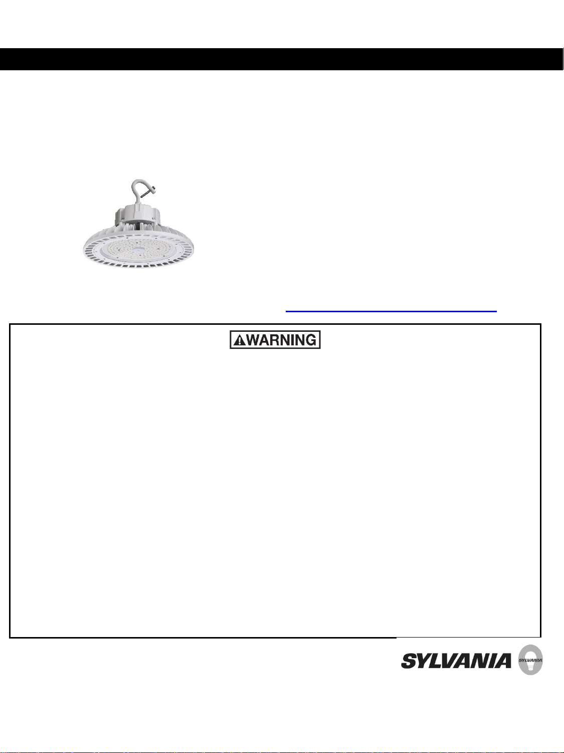
Installation Guide –ValueLED™ UFO High Bay
The UFO High Bay luminaires are
environmentally preferable LED alternatives to
traditional HID luminaires, offering up to 78%
in energy savings. Ideal in place of traditional
luminaires, or as new installations, the UFO
High Bay series is offered use in warehouses,
manufacturing facilities, big-box retail,
gymnasiums, and loading docks.
For warranty coverage, please register at www.sylvania.com/warrantyregistration.
PLEASE READ ALL INSTRUCTIONS BEFORE ATTEMPTING INSTALLATION
•
TO PREVENT PERSONAL INJURY OR PRODUCT DAMAGE ONLY LICENSED ELECTRICIANS SHOULD
PROVIDE ALL INSTALLATION SERVICES.
•
TO AVOID ELECTRIC SHOCK OR COMPONENT DAMAGE DISCONNECT POWER BEFORE ATTEMPTING
INSTALLATION OR SERVICING.
•
THIS PRODUCT MUST BE INSTALLED IN ACCORDANCE WITH THE NATIONAL ELECTRIC CODE (NEC) AND
ALL APPLICABLE FEDERAL, STATE AND LOCAL ELECTRIC CODES AND SAFETY STANDARDS.
•
USE CAUTION WHEN HANDLING THIS PRODUCT DURING OR AFTER OPERATION AS IT MAY BECOME HOT
AND CAUSE BURNS. DISCONNECT PRODUCT AND ALLOW COOLING PRIOR TO SERVICING.
•
ANY ALTERATION OR MODIFICATION OF THIS PRODUCT IS EXPRESSLY FORBIDDEN AS IT MAY CAUSE
SERIOUS PERSONAL INJURY, DEATH, PROPERTY DAMAGE AND/OR PRODUCT MALFUNCTION.
•
TO PREVENT PRODUCT MALFUNCTION AND / OR ELECTRICAL SHOCK THIS PRODUCT MUST BE
PROPERLY GROUNDED.
•
THIS LUMINAIRE IS DESIGNED TO OPERATE IN AMBIENT TEMPERATURES
•
100/150/200W MODELS RANGING FROM -40°F TO +122°F (-40°C TO +50°C).
•
240W MODELS RANGING FROM -40°F TO +113°F (-40°C TO +45°C).
3597711
3597711
SAFETY PRECAUTIONS:
IMPORTANT: READ CAREFULLY BEFORE INSTALLING THE FIXTURE. RETAIN FOR FUTURE REFERENCE.
GENERAL: Upon receipt of the fixture, thoroughly inspect for any freight damage which should be brought to the attention of the delivery carrier.
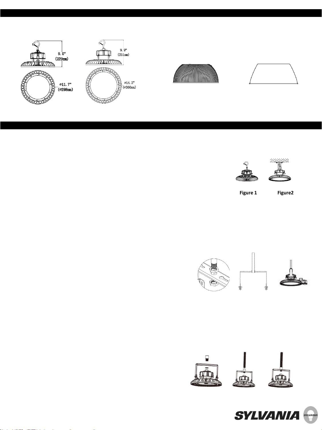
100/150W 200/240W
Refractor Reflector
INSTALLATION:
Hook Mount
•Screw the hook into the ValueLED™ UFO High bay light fixture, then tighten securely (Figure 1).
•Hang the fixture from the hook and secure to protect the fixture from falling (Figure 2).
•After completion, please wire in accordance with all local regulations.
•You have successfully completed the installation.
½” NPT Mount
•Attach U-bracket using four supplied screws into pre-tapped holes in the top of the
housing
•Place the ½” NPT with nut through center hole in bracket and attach second nut to the
end of the NPT (Figure 3 and 4).
•After completion, please wire in accordance all local regulations. Once the installation and
wiring are complete, the luminaire can be adjusted up to 50 degrees by adjusting the
screws connected to the bracket accessory.
•Installation is now complete (Figure 5).
¾” NPT Mount
Figure 3 Figure 4 Figure 5
•Attach U-bracket using four supplied screws into pre-tapped holes in the top of the housing
•Unscrew the nut on a ¾” to ½” adaptor (supplied by others)
•Place the ½” end of the NPT adaptor through center hole in bracket and attach a nut to the
½” end of the NPT adaptor (Figure 6).
•Insert the incoming piece of ¾” NPT to the adaptor (Figure 7).
•After completion, please wire in accordance all local regulations. Once the installation and
wiring are complete, the luminaire can be adjusted up to 50 degrees by adjusting the screws
connected to the bracket accessory.
•Installation is now complete (Figure 8).
Figure 6 Figure 7 Figure 8
 Loading...