

Page 1
OPERATING THE SYLVANIA FOUR CHANNEL SYSTEM
RQ3748
Page 2
TABLE
Introduction
Accessory
Initial
Connecting
Sound
Sound
Sound
Warranty
OF CONTENTS
Page
2
Components
Hook-Up
Phono Jacks
Aux Jacks
Tape One Jacks
Tape Two Jacks
Pre-Amp to Amp Jacks
Two Channel Bridge Operation 5
Antenna Connections
Unswitched Outlets 6
Switched Outlet 6
Protective Circuits
System
System
System
Speaker System Selection
AM Tuning
FM Tuning
Phono
9
Aux
Two Channel Tape Play
Four Channel Tape Play
Recording Two Channel Source
Recording Four Channel Source
Record Source One/Playback
Source Two
Record Tape "A" onto Tape "B"
10
4
Accessory
4
4
Indicators
Controls
Operation
8
8
9
9
3
Components
4
4
4
5
b
7
7
8
9
9
9
9
9
INTRODUCTION
You are the owner of one of the most
sophisticated and versatile audio instruments on the market. Your Sylvania Four
Channel Receiver will reproduce discrete
tape and disc sources and decode two
channel sources into four channel matrix.
Separate tuning and signal strength
meters make possible outstanding tuning
accuracy.
The easy-to-read control panel has push
button controls and lighted function
indicators.
Your receiver features a switched main
and remote speaker system so you can
operate all your speakers from the control
panel.
Separate bass and treble controls
for the front and rear speakers enable
you to tailor the sound output to suit
many seating arrangements.
You can change the position of your
speakers electronically using the Image
Orientation Control. You will find this
especially useful when playing special
effects recordings or when the seating
arrangement in a room precludes the most
desirable speaker positioning.
The possibility of attaching a number of
accessory components is a feature you
will certainly want to take advantage of.
We have mentioned just a few of the many
exciting features. As you read these
instructions, you will discover that you
have chosen a receiver capable of being
the heart of a truly professional audio
system.
Read carefully so you can enjoy the full
potential of your Sylvania Four Channel
Receiver.
2
Page 3
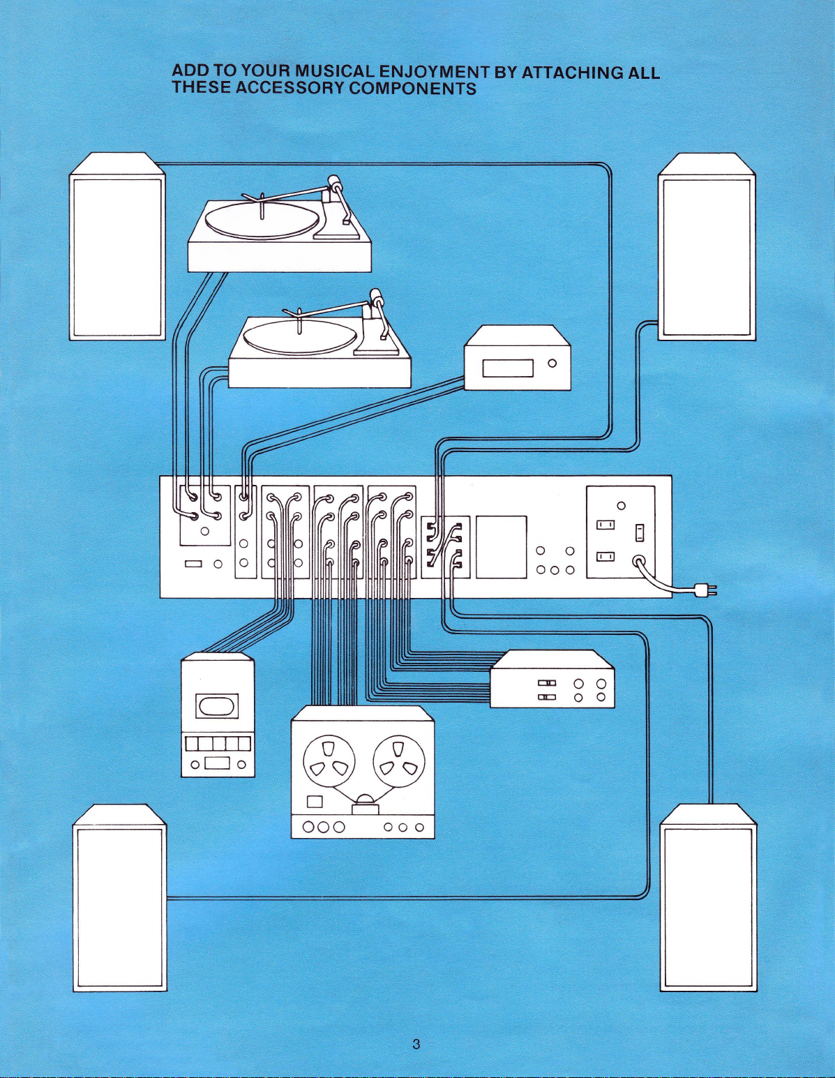
ADD
TO YOUR MUSICAL ENJOYMENT BY ATTACHING ALL
THESE ACCESSORY COMPONENTS
3
Page 4

INITIAL
1.
Connect speakers to appropriate main (PP)
2.
Slide high sensitivity ferrite rod AM antenna
3. Connect the leads from the 300 ohm FM di-
4.
Place the bridge switch (KK) in the 4 channel
5. Plug in AC line cord (UU) to a 120 volt, 60 Hz
HOOK-UP
and/or remote (QQ) terminals on rear of
receiver. Always be sure positive and negative
speaker leads are connected to the corresponding positive and negative speaker
terminals.
assembly (contained in separate bag) into
holder (LL) and plug in connector.
pole antenna under the 300 ohm terminals
(RR).
position.
outlet.
CONNECTING ACCESSORY
COMPONENTS
Phono
Jacks
(FF)
There are two phono inputs on the jackplate to provide for the possible use of two turntables.
1.
Select either phono one or two jacks and plug
turntable cables into the appropriate left and
right jacks. Connect ground wire under phono
ground terminal.
2.
Move phono selection switch (NN) to corre-
sponding position one or two.
NOTE:
must be used.
Aux
Jacks
Plug the output of any accessory equipment with
a preamplifier into the appropriate left, right, front
and rear jacks. Typical accessories are:
1.
4 ch. CD4 turntable or separate disc
demodulator.
2.
4 ch. 8-track discrete tape play deck.
A turntable with a magnetic cartridge
(GG)
3. Microphone or musical instruments with preamplifier, up to a combined total of four
sources.
4.
2 ch. tape player (front jacks preferred).
Tape
One
Jacks
(HH)
There are two types of jacks, record and play.
When you record on accessory tape unit use
"record"
jacks.
and rear jacks, for two channel operation it is best
to use the "front" jacks. Connect the accessory to
the appropriate L, R, front and rear jacks. Typical
accessories are:
1.
A two channel reel-to-reel or cassette tape
2.
A four channel eight track discrete tape play/
3. A four channel reel-to-reel discrete tape play/
4.
A four channel discrete FM decoding unit can
Tape
These jacks may be used with the same accessory
units as the tape one jacks. However, it is recommended that they be used for a four channel
to-reel record/playback deck to enable you to
record from another accessory unit that has been
plugged into the tape one or aux jacks.
Pre-Amp
The pre-amplifier signals are relayed from the
output jacks through jumpers back into the main
4
jacks. When playing tapes use the "play"
For four channel operation use both front
play/record deck can be plugged into the
front play and record jacks.
record deck can be plugged into the front and
rear play and record jacks.
record deck can be plugged into the front and
rear play and record jacks.
be plugged into the tape play jacks and into
the FM composite signal jack (OO). This will
enable you to receive 4 channel FM discrete
programming when it is available.
Two
Jacks
(II)
reel-
to Amp
Jacks
(JJ)
Page 5

amplifier input jacks. The signal path can be interrupted to insert accessory equipment such as an
environmental equalizer, to shape frequency
response to suit room acoustics, or high and low
pass electronic crossover filters for connecting
the amplifier to operate in a bi-amp configuration.
The pre-amplifier output can also be used to drive
separate slave power amplifiers. In all
power
off
before removing jumpers.
environmental equalizer; or slave power amplifiers
with-or-without its own pre-amplifier outputs:
1.
Turn power off.
2.
Remove the jumpers.
3. Plug cables from the receiver pre-amplifier
output jacks to the input jacks on the accessory
unit.
4.
Plug the cables from the output of the acces-
sory to the "amp-in" jacks of the receiver.
NOTE:
level output jacks for this use. DO NOT use the
main high level output, rather use a commercially available "Y" connector at the preampout jacks of the receiver. One side of the "Y"
goes to the accessory input, the other goes to
the amp-in jacks of the receiver.
5. Be sure right, left, front and rear cables are
connected to appropriate jacks.
When using electronic crossover filters for bi-amp
operation,
for four channel reproduction. Two of the amplifiers
will be used for high frequency information and
two for low frequency.
1.
Turn power off.
2.
Remove the jumpers.
3. Plug cable from the left front pre-amplifier output to the electronic crossover filter input.
4.
Plug cable from the low pass section of the
ter to the left front amplifier input.
Some slave amplifiers do not have low
you will not be able to utilize the unit
cases, turn
To attach an
fil-
5. Plug cable from the high pass section of the
filter to the left rear amplifier input.
6. Repeat the same procedure for the right channel output and input.
7. Connect the left low frequency speaker leads
to the left front positive and negative speaker
terminals on the jackplate.
8. Connect the left high frequency speaker
leads to the left rear positive and negative
speaker terminals.
9. Repeat the same procedure to connect the
right low and high frequency speaker leads
to the right speaker terminals.
10.
Push the stereo button (X) on your receiver in.
Two
Channel
This procedure will enable you to convert from four
channel operation at 50 watts per channel to two
channel operation at 125 watts per channel.
1.
Turn power off and refer to diagram on the
jackplate.
2.
Connect positive lead from left speaker to left
front positive speaker terminal.
3. Connect negative lead from left speaker to left
rear positive speaker terminal.
4.
Connect negative lead from right speaker to
right rear positive terminal.
5. Connect positive lead from right speaker to
right front positive terminal.
6. Move switch (KK) to 2 channel bridge position.
7. Push the stereo button (X) on your receiver in.
NOTE:
Antenna Connections
The jackplate has provisions for attaching high
gain external antennas for reception of distant
stations.
5
Bridge Operation
Be sure your speakers have a high enough
rating to dissipate the increased power.
(RR)
(KK)
Page 6

External
1.
2.
NOTE:
for proper operation.
External
1.
2.
External
1.
2.
3. Attach the outer shield of 75 ohm lead-in to
Unswitched
Plug accessory components such as turntables or
tape decks into these outlets. The outlets remain
live when the receiver power switch is turned off.
Switched
Plug associated electronic components such as an
environmental equalizer into this outlet. The outlet
will go dead when the receiver power is turned off.
NOTE:
tape decks.
Protective
Your receiver incorporates four protective systems
against abnormal operating conditions that could
cause damage to the receiver or accessory
equipment.
Long
Line
AM
Antenna
Connect the lead in wire from antenna to AM
terminal.
Connect the ground terminal (RR) to a good
earth ground, such as a water pipe.
The AM ferrite rod must remain attached
FM
Antenna
Disconnect all FM antennas attached to
receiver.
Connect the leads from a 300 ohm external
FM antenna, or less efficient TV antenna,
under the two 300 ohm FM antenna terminals.
FM
Antenna
Disconnect all FM antennas attached to
receiver.
Attach the center conductor of coaxial lead-in
to the 75 ohm FM antenna terminal.
the ground terminal.
Outlets
Outlet
Do not use this outlet for turntables or
Circuits
300 Ohm
75 Ohm
(SS)
(TT)
Electronic
Protects the output devices from improperly
applied external loads. There is no visual or audio
indication of this in operation.
Thermal
Will shut the entire unit off automatically if the
internal temperature becomes excessive. The unit
will automatically come back on when it has cooled.
Check for obstructions over the vent screen area.
Circuit
Provides protection against certain electrical
overloads. If your unit suddenly goes off, wait for
a short period of time to determine whether the
thermal switch or the main circuit breaker has
activated.
back on, push the button (MM) in to re-set the
breaker. Do not hold the button depressed for an
extended length of time. If frequent resetting is
required consult your authorized Sylvania service
dealer.
Circuit
There are four temperature compensated circuit
breakers inside the unit, one for each major
speaker circuit (left, right, front and rear). These
breakers will turn your speakers off automatically
if they are receiving too much current. After a
short interval of time the speakers will auto-
matically reset. If they continue to cycle off, check
speaker wiring for shorts, damaged speakers or
overload due to improper speaker load impedance.
6
Current
Switch
Breaker-Main
If the unit does not automatically come
Breaker-Speakers
Limiting
Page 7

SOUND SYSTEM INDICATORS
A—FM Center Tune Meter —indicates best FM
reception when needle is centered.
B—Signal Strength Meter—AM signal is strongest
and FM signal has highest signal to noise ratio
when needle is as far to right as possible.
C—AM Dial —indicates AM stations. 540 to 1600
kHz.
D—FM
E—Log
F—Function Indicators —indicates the program
Dial-indicates FM stations. 88 to 108
MHz.
Scale — quick reference tuning guide, in
addition to the frequency dials, log scale
erence numbers can be used to relocate
favorite stations.
source i.e., AM, FM, FM stereo, etc.
ref-
SOUND SYSTEM CONTROLS
G—Tuning—to select AM & FM stations.
H —Image Orientation—to electronically change
speaker position.
I
—Dial Light —to adjust dial light intensity. Push
button in to dim light.
J—Power —to turn unit on and off.
K—4 Channel Stereophone Jacks —receptacles
into which stereo or 4 channel headphones
are plugged.
L—Main
M —Remote Speaker Switches—to control
N —FM Mute— eliminates interstation noise and
O—High and Low Filters —High filter reduces
Speaker Switches —to control main
speaker system.
remote speaker system.
weak signal stations with excessive noise
when tuning.
high frequency noise. Low filter reduces sub-
sonic noise and rumble.
P—Left
Q—Master Volume—to adjust audio volume on
R—Right
S—Bass—to adjust low frequency sounds. Front
T—Treble—to adjust high frequency sounds.
U—AM—to
V—Mono—to engage system to convert two or
W—FM—to select FM Band.
X—Stereo—to engage system to receive FM
Y—Phono —to engage system for record play.
Z—4 Channel Discrete —to engage system to
AA—CD4 Aux—to engage system for CD4 de-
BB—SQ Matrix—to decode four channel matrix
CC—SQ Blend—to provide more front to rear
DD—Tape Monitor—to engage system for accesEE—Loudness—to boost low frequencies for
Front and Rear Level—to adjust audio
output levels on left front and rear speakers.
all speakers simultaneously.
Front and Rear Level—to adjust audio
output levels on right front and rear speakers.
knob controls front speakers. Rear knob
trols rear speakers.
Front knob controls front speakers. Rear
knob controls rear speakers.
select AM Band.
four channel sources to monaural to balance
the system and to reproduce a monaural
source on all four speakers.
stereo broadcasts and to play stereo records
and tapes.
receive four channel discrete programming.
modulator system or additional components
and musical instruments equipped with preamplifiers.
FM broadcast or records or, to derive four
channel ambient sound from any two channel
stereo source.
separation when listening to solo performances with the SQ matrix button depressed.
sory tape play and tape record monitoring.
proper tonal balance at low listening levels.
con-
7
Page 8

SOUND SYSTEM OPERATION
Speaker
Each of the four main or remote speaker switches
(L or M) controls two speakers. You may at any
time use all eight speakers in any combination of
two at a time.
The image orientation control (H) enables you to
electronically change the positions of your
speakers. Assume that in the diagram:
speakers 1 and 2 are your main front speakers and
3 and 4 your main rear speakers. If you move the
image orientation control 1/4 turn to the "RIGHT"
position,
speakers; 1 and 3 your main rear speakers. A full
1
/4 turn to the "REAR" position makes 3 and 4 your
main front speakers; 1 and 2 your main rear
speakers. By continuing the
rotate your speakers. The volume and tone
trols will operate on whatever speakers are designated front, rear, left, right. The main and remote
speaker switches will however control the
speakers originally connected in the "FRONT"
position.
The placement of furniture in your room will determine the desired position.
System
Selection
2 and 4 become your main front
turn,
you continue to
con-
AM
Tuning
1.
Set individual level controls (P) and (R) to "5"
position and master volume control (Q) to "4"
position.
2.
Push power button (J) in.
3. Push AM button (U) in.
4.
Rotate tuning control (G) to select desired
station as indicated on AM dial (C). Reception
is optimum when needle on signal strength
meter (B) is as far to right as possible.
5. Select desired speaker systems.
6. To operate all four speakers, depress mono
button (V).
FM
Tuning
1.
Push power button (J) in.
2.
Push FM button (W) in.
3. Rotate tuning control (G) to select desired
station as indicated on FM dial (D). Reception
is optimum when needle on FM tuning meter
(A)
4.
is centered.
If you have an external antenna, rotate until
needle on signal strength meter (B) is as far
right as possible.
5. If program is being broadcast in monaural,
push mono button (V) in.
6. If program is being broadcast in 2 channel
stereo, push stereo button (X) in or to obtain
a four channel effect, push SQ matrix button
(BB) in. Some stations broadcast matrix programming.
In that case, push SQ matrix
button in.
7. To listen to a distant station with a weak signal
or listen in stereo to a station with a poor
quality stereo signal it will be necessary to
switch the FM mute switch (N) to the out
position.
8. Select desired speaker system.
8
Page 9

Phono
1.
Push power button (J) in.
2.
Push phono button (Y) and select phono one
or two with switch (NN) on jackplate.
3. When playing monaural records, push mono
button (V) in.
4. When playing stereo records, push stereo button (X) in or, to obtain a four channel effect,
push SQ matrix button (BB) in. Some record-
ings have been matrixed for four channel.
Push SQ matrix button in.
5. Select desired speaker system.
6. Additional instructions under "Connecting
Accessory Components" section. Also refer to
instructions contained with your turntable.
CD4 Aux
1.
Connect accessory to aux input jacks on jack-
plate.
Typical examples are described under
"Connecting Accessory Components" section.
2.
Push power button (J) in.
3. Push aux button (AA) in.
4.
Push in appropriate mode button; mono, stereo,
4 ch. discrete or SQ matrix for source selected.
5. Select desired speaker system.
Two
Channel
1.
Connect accessory tape equipment to rear of
unit. See "Connecting Accessory Components"
section for preferred jacks for type of equip-
ment being used.
2.
Push power button (J) in.
3. Push in aux (AA) or tape monitor button (DD)
one or two depending on which jacks on rear
of unit you have plugged into.
4.
Push in stereo button (X), or to obtain a 4
channel effect, push in SQ matrix button (BB).
5. Select desired speaker system and adjust all
tone and volume controls as previously
described.
6. For additional information consult the instructions contained with your accessory equipment.
Four
Channel
1.
Repeat all steps under two channel tape play
except step number 4.
2.
Push 4 ch. discrete button (Z) in.
Recording
1.
Connect accessory tape equipment to rear of
unit. See "Connecting Accessory Components"
section preferred jacks for type of equipment being used.
2.
Push power button (J) in.
3. Push 2 ch. stereo program source (FM, phono
or aux) button in. If equipment being used:
A. Has a tape monitor head
B. Does not have a tape monitor head
4.
Select desired speaker system and adjust
tone and volume controls as previously
described.
5. For additional information consult the instructions contained with your accessory equipment.
Tape
Play
Discrete
Two
Channel
1.
Push in tape monitor button (DD) one
or two depending on which jacks are
being used.
2.
Push stereo button (X) in, or to obtain
a 4 ch. effect, push SQ matrix button
(BB)in.
1.
Push stereo button (X) in.
Tape
Play
Source
Recording
1.
Connect accessory four channel discrete
2.
Push power button (J) in.
3. Push in aux button (AA) or tape monitor one
4.
Push4ch.discretebutton(Z)in.
5. If tape unit recording the program has a tape
6. Select desired speaker system and adjust tone
7. For additional information consult the instruc-
NOTE:
discrete and SQ matrix buttons will affect the
record signal unless the tape monitor button is
depressed,
tape play to tape record jacks (internal on some
machines with a tape out that is not a true monitor).
Record
1.
Follow previous instructions on recording two
2.
Remove any connections to the "Tape Play"
3. Push in mono, stereo, 4 ch. discrete or SQ
4.
Select desired speaker system and adjust all
NOTE:
able program material (i.e. copy a "one of a
recording on to tape) while playing something of an
urgent nature (educational tape for study).
Record
1.
Connect "Tape A" unit to the aux jacks (GG)
2.
Push power button (J) in.
3. Push in aux button (AA) or tape monitor one
4.
Connect "Tape B" unit to tape one jacks (HH)
5. If the unit recording the program has a tape
6. If the unit recording the program does not
7. Select desired speaker system and adjust tone
8. For additional information consult the instruc-
Four
Channel
source and tape equipment to rear of unit. See
"Connecting Accessory Components" section
for preferred jacks for type of equipment being
used.
button (DD) for selecting 4 channel discrete
source.
monitor head, push in tape monitor button (DD)
one or two depending on which jacks are being
used by this unit.
and volume controls as previously described.
tions contained with your accessory equipment.
When recording, the mono, stereo, 4 ch.
and there is no external short from the
Source
or four channel source up to and including the
step for "Tape Monitor Head" equipment
(depress tape monitor button (DD).
jacks controlled by button (DD) just depressed,
and plug "Source Two" into those jacks.
matrix button depending on what has been
added as "Source Two".
tone and volume controls as previously
described.
This hookup allows you to record pleasur-
"Tape A"
or tape one jacks (HH) on rear of receiver.
See "Connecting Accessory Components"
section for preferred jacks for type of equip-
ment being used.
button (DD) depending upon which jacks the
"Tape A" unit was plugged into.
or tape two jacks (II) on the rear of the receiver
(whichever is not in use by "Tape A" unit).
monitor head push the tape monitor button
(DD) in, one or two depending upon what jacks
it is plugged into.
have a tape monitor head you must push in
the appropriate mono, stereo or 4 ch. discrete
button corresponding to the original program
source of "Tape A".
and volume controls as previously described.
tions contained with your accessory equipment.
One/Playback
onto
Source
Source
"Tape B"
Two
kind"
9
Page 10

WARRANTY
Receivers
GTE Sylvania presents
answer form
you
are
WHO
IS
The original retail purchaser.
purchaser mail
to facilitate service should
WHAT
The receiver
from date
HOW
ARE YOU
The Sylvania dealer from whom
receiver,
repair
within
You must deliver your receiver
or
his
service...and pick
performed.
to
protected.
PROTECTED?
IS
or
the
authorized Service Contractor's place
give
the
PROTECTED
and its
of
purchase.
or his
authorized Sylvania Service Contractor, will
replace
warranty period.
its
warranty
you a
warranty registration card
PROTECTED?
any
it up
clear understanding
We
suggest
it be
required.
AND FOR HOW
parts
are
covered
part which fails under normal
to
from
him
to you in
you
your Sylvania dealer
when service
question-and-
of
just
how
the
original retail
to GTE
LONG?
for two (2)
purchased your
THIS
We
recommend
SPECIFICATIONS SUBJECT
Sylvania
years
use
of
business
has
been
IS THE GTE
Sylvania
WITHOUT NOTICE
for
WHO PAYS
For two
Dealer from whom
authorized Sylvania Service Contractor, will honor this
warranty without
the
two (2)
or service charges.
ARE
REPLACEMENT PARTS PROTECTED?
Yes,
replacement parts
original warranty period.
WHAT
The Sylvania dealer
Contractor located
will honor this warranty
iod.
Service will
slip
to the
you move since
your purchase.
SYLVANIA WARRANTY
Replacement
THE
(2)
IF YOU
dealer
TO
LABOR
years after
year warranty period,
MOVE?
CHANGE
the
you
any
labor
are
or an
in the
be
he
Parts
for the
expedited
or
service contractor
will
CHARGE?
date
of
purchased your receiver,
protected
not,
purchase,
or
service charges. After
you pay for
for the
authorized Sylvania Service
area
to
balance
if you
initially, have
which
of the
will present your sales
in the
the
balance
you
warranty per-
area
any
record
Sylvania
or his
move
to
labor
of the
which
of
Printed
in
U.S.A.
Entertainment
Products
Group,
700
Ellicott
Street,
Batavia,
fHTB SyiVAINIA
^^"^•^
INCORPORATED
New
York
14020
W-15
05-36029-1
 Loading...