

Sylvania OPTOTRONIC OT240W/3X24V/120-240V/JBX Installation Manual
OT240W/3X24V/120-240V/JBX
www.sylvania.com
Power Supply Specifications:
Safety Warnings:
System Life/Warranty:
Mounting Instructions:
Tools Required:
before use
Installation Guide
1. Estimate the maximum allowed wiring distance between the power supply and the LED
modules. Both a) and b) have to be taken into account.
a. Refer to document ECS126 for wiring distance limitations based on the LED load
2. Select the location to install the OPTOTRONIC OT240W/3X24V/120-240V/JBX power supply
within the estimated remote mounting distance range.
3. Securely mount the OT240W/3X24V/120-240V/JBX power supply to a flat surface using four
screws (not supplied). Mounting holes are located at the both ends of the power supply.
and wire gauge used.
b. Recommended, the wiring distance in any installation should not exceed 32 ft due
to a possible EMI effects.
Note: Although, it is possible to exceed the 32 ft EMI related remote mounting
distance, if the LED load and wire gauge used allows, the installer must take
precautions and test the effects of EMI on the system.
Note: The power supply should be installed in an environment with a maximum
ambient temperature not exceeding 158⁰F (70⁰C), away from heat-producing
components or devices. Air should be allowed to move freely around an individual
unit.
a. Use #10 size screws, appropriate for the material it is installed onto.
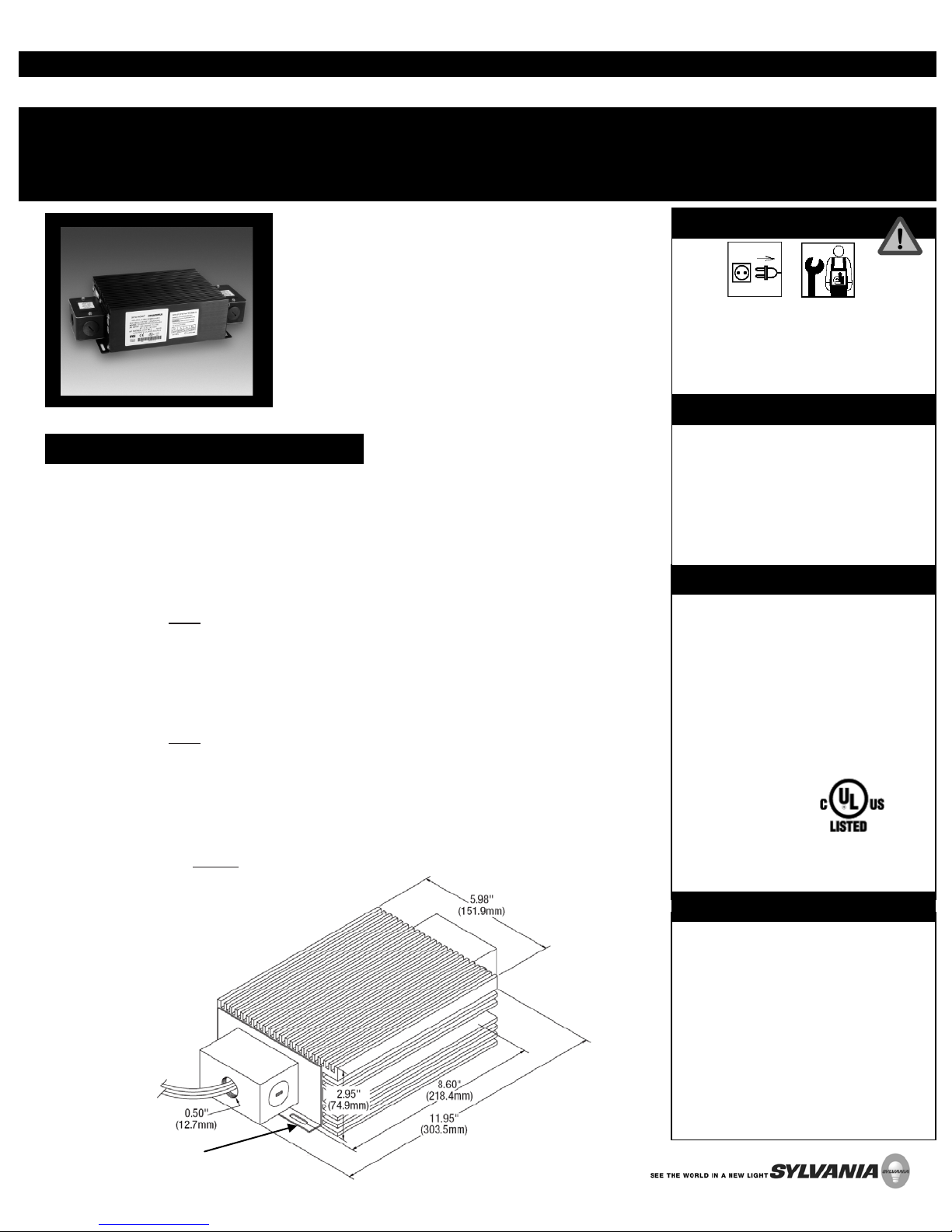
The OPTOTRONIC® power supply OT240W/3X24V/120240V/JBX from SYLVANIA is a compact and electronically
stabilized 24V DC constant voltage power supply. It works
on a wide range of input voltages, from 120 to 240 VAC
enabling worldwide use on single-phase AC power lines.
The OT240W/3X24V/120-240V/JBX power supply has three
independent Class II 80W outputs for a total of 240W.
OPTOTRONIC power supplies are protected against open
circuit, short circuit, overload and overheating conditions.
They meet the highest industry standards.
Disconnect
All electrical installations should be made
according to the National, State and Local
codes and regulations.
• Phillips screwdriver
• Wrench
• Wire cutters (or means to cut wires)
• Wire nuts (or means to connect wires)
• Eye protection
• ESD protection equipment
• Input Voltage: 120-240V AC
• Input Frequency: 50/60Hz
• Input Power: 287W
• Power Factor: 0.99
• Output Voltage: 24V DC
• Output Power: 240W (3 x 80W)
• Efficiency: 85% Typical
• Ambient Temperature Range: -22⁰F to
158⁰F (-30⁰C to 70⁰C)
• Classification: Class II
Install by a
qualified electric ian
IP66
UL File # E320395
Mounting Holes
LED128
• OPTOTRONIC LED Power Supply
Products are covered by our LED
system warranty, a comprehensive LED
module and power supply warranty.
For additional details, refer to the
latest version of the LED warranty
available in the Literature section of
www.sylvania.com/led.
Gray (+)
Black (-)
Gray (+)
Black (-)
Gray (+)
Black (-)
80W (max)
80W (max)
80W (max)
PRIMARY
(AC) Side
SECONDARY
(DC) Side
Black (L)
White (N)
Green (GND)
INPUT
Line AC
120-240V AC
OUTPUT
24V DC
3 x 80W
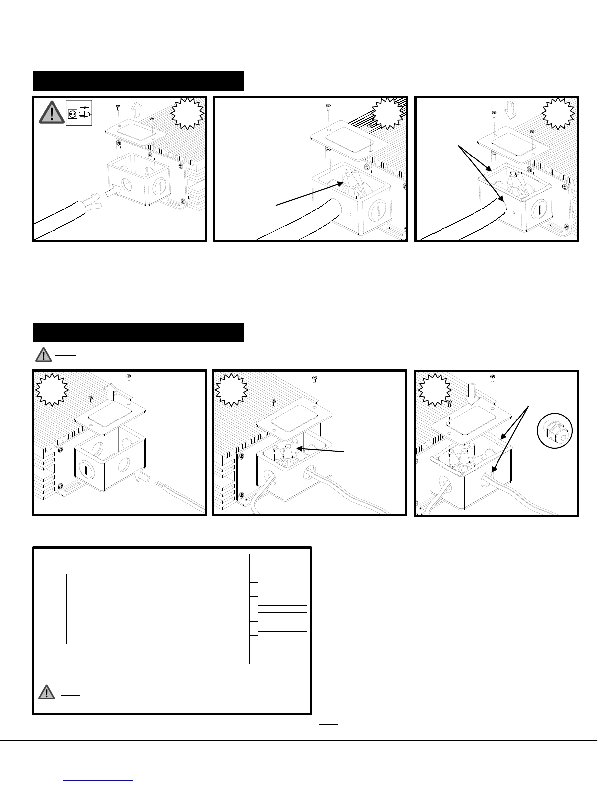
Wiring Instructions – Primary Side:
AC Wires/Cable
sealant
Wiring Instructions – Secondary Side:
sealant
4
5
6
AC INPUT: 120-240V AC
L - Black
N – White
GND – Green/Yellow
Wire Nuts
Water-tight
1. Remove the cover of the connection box on the AC side. Insert the AC Line supply cable through one of the access holes
2. Connect the AC Line supply cable to the wires of the power supply. Observe polarity.
3. Tighten conduit and reinstall the cover. Apply sealant for water-proof sealing on the conduit and the cover (for outdoor
Note: Refer to the respected LED module Product Information Bulletin and Installation Guide to verify compatibility and particular electrical
requirements and limitations that may apply.
provided - Use conduit, appropriate for the application and the installation.
installations).
DC OUTPUT: 3x 24V DC
Class II
Water-tight
+24V – Gray
GRN – Black
MAX: 80W/chnl
Wire Nuts
4. Remove the cover of the connection box on the DC side.
Insert the LED module leader cable through one of the
access holes provided
− Use conduit, appropriate for the application and the installation,
if required.
5. Connect the LED Leader cable/wires to one set of output
wires (channel) of the power supply. Observe polarity.
− Repeat steps 4 and 5 for adding output connections. Use the
Note: The OT240W/3X24V/120-240V/JBX has three independent 24V
output channels, each rated for a maximum LED load of 80W.
6. Seal connection holes and reinstall the cover.
additional access holes for wire access.
− Appropriate wet-rated grommets may be used to seal the
connection holes (not provided).
− For outdoor installations: Apply sealant for water-proof sealing
on the conduit(s)/grommet and the cover.
Optional Wet
rated grommet
(Not-provided)
OSRAM and OPTOTRONIC are registered trademarks of OSRAM GmbH.
Specifications subject to change without notice
1-800-LIGHTBULB (1-800-544-4828) © 2010 OSRAM SYLVANIA Inc. 08/10
Note: For outdoor installations, the cable/cord connecting the LED module to the
power supply must be rated and marked W, PLTC, CL3R and “Sun Resistant”.
 Loading...