

Page 1
SUPPLEMENT
SERVICE MANUAL
This service manual shows only the differences between
the model FDR-90E and the original model DVR90DE.
All other information is described in the service manual
of the model DVR90DE.
DVD RECORDER
FDR-90E
Page 2

IMPORTANT SAFETY NOTICE
Proper service and repair is important to the safe, reliable operation of all
Funai Equipment. The service procedures recommended by Funai and
described in this service manual are effective methods of performing
service operations. Some of these service special tools should be used
when and as recommended.
It is important to note that this service manual contains various CAUTIONS
and NOTICES which should be carefully read in order to minimize the risk
of personal injury to service personnel. The possibility exists that improper
service methods may damage the equipment. It also is important to
understand that these CAUTIONS and NOTICES ARE NOT EXHAUSTIVE.
Funai could not possibly know, evaluate and advice the service trade of all
conceivable ways in which service might be done or of the possible
hazardous consequences of each way. Consequently, Funai has not
undertaken any such broad evaluation. Accordingly, a servicer who uses a
service procedure or tool which is not recommended by Funai must first
use all precautions thoroughly so that neither his safety nor the safe
operation of the equipment will be jeopardized by the service method
selected.
TABLE OF CONTENTS
Block Diagrams . . . . . . . . . . . . . . . . . . . . . . . . . . . . . . . . . . . . . . . . . . . . . . . . . . . . . . . . . . . . . . . . . . . . . . . . 1-1-1
Schematic Diagrams / CBA’s and Test Points. . . . . . . . . . . . . . . . . . . . . . . . . . . . . . . . . . . . . . . . . . . . . . . . . 1-2-1
Different parts from original model (DVR90DE) . . . . . . . . . . . . . . . . . . . . . . . . . . . . . . . . . . . . . . . . . . . . . . . 1-3-1
Manufactured under license from Dolby Laboratories. "Dolby" and
the double-D symbol are trademarks of Dolby Laboratories.
Page 3
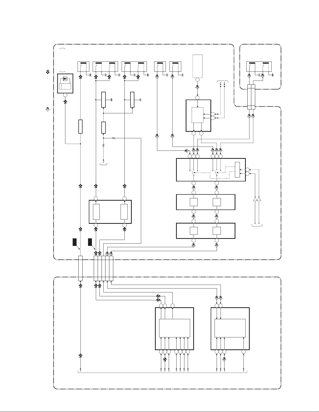
Audio Block Diagram
)
DIGITAL
AUDIO OUT
AUDIO-L
OUT1
JK4104
OPTICAL
FIBER OPTIC
TRANS MODULE
IC4301
COAXIAL
(
AUDIO OUT
JK4301
BLOCK DIAGRAM
AUDIO-L
OUT2
JK4105
AUDIO-R
OUT1
AUDIO-R
OUT2
JK4104
AUDIO-L
IN1
AUDIO-R
JK4105
IN1
TU4001
SIF OUT
14
TO SYSTEM CONTROL
BLOCK DIAGRAM
JK4602
AUDIO-L
IN2
AUDIO-R
IN2
1
REC AUDIO SIGNAL PB AUDIO SIGNAL
Q4301
WF7
BUFFER
)
OP AMP
(
IC4421
WF6
Q4425 Q4424
TO
1
OP AMP
2
MUTE-ONDRIVE
A-MUTE
SYSTEM CONTROL
BLOCK DIAGRAM
Q4426
7
OP AMP
6
MUTE-ON
)
L-CH
MTS/SAP AUDIO
(
SIGNAL PROCESS
IC4041
425
IN1TUIN2
(L-CH)
(AUDIO INPUT SELECT)
IC4164
)
OP AMP
(
IC4166
)
OP AMP
(
IC4165
OP
OP
21
MTS/SAP
AUDIO
SIGNAL
PROCESS
R-CH
30
29
3
2
AMP
1
2
AMP
1
(R-CH)
SUB-SCL
24 27
111514
IN1TUIN2
13
6
OP
AMP
7
6
OP
AMP
7
SUB-SDA
AUDIO(L)-IN2
AUDIO(R)-IN2
88
10 10
CN4104 CN4601
9 10
SW CTL
AV CBA JACK CBA
Q4161
Q4162
AUDIO-SW2
AUDIO-SW1
18 18SPDIF
CN6 CN4502
SPDIF
AUDIO-OUT(L)
AUDIO-OUT(R)
25 25
27 27
CN7 CN4401
DVD-AUDIO-MUTE
DVD-AUDIO-IN(L)
DVD-AUDIO-IN(R)
19 19
23 23
21 21
L-CH
IC13 (AUDIO D/A CONVERTER)
BCK
1-1-1
7
8
R-CH
123
DATA
LRCKMDMC
TO DIGITAL
SIGNAL
11
MUTE
PROCESS
BLOCK
AUDIO D/A
CONVERTER
131416
DIAGRAM
TO SYSTEM CONTROL
BLOCK DIAGRAM
1
5
R-CH
L-CH
AUDIO A/D
CONVERTER
IC12 (AUDIO A/D CONVERTER)
131415
SCK15ML
LRCK
BCK
DATA
16
SYSCLK
DVD BE MAIN CBA
E6550BLA
Page 4

SCHEMATIC DIAGRAMS / CBA’S AND TEST POINTS
Standard Notes
WARNING
Many electrical and mechanical parts in this chassis
have special characteristics. These characteristics
often pass unnoticed and the protection afforded by
them cannot necessarily be obtained by using replacement components rated for higher voltage, wattage,
etc. Replacement parts that have these special safety
characteristics are identified in this manual and its
supplements; electrical components having such features are identified by the mark " # " in the schematic
diagram and the parts list. Before replacing any of
these components, read the parts list in this manual
carefully. The use of substitute replacement parts that
do not have the same safety characteristics as specified in the parts list may create shock, fire, or other
hazards.
Notes:
1. Do not use the part number shown on these drawings for ordering. The correct part number is
shown in the parts list, and may be slightly different
or amended since these drawings were prepared.
2. All resistance values are indicated in ohms
3
(K=10
3. Resistor wattages are 1/4W or 1/6W unless otherwise specified.
4. All capacitance values are indicated in µF
(P=10
5. All voltages are DC voltages unless otherwise
specified.
, M=106).
-6
µF).
1-2-1 SC_FN1
Page 5

LIST OF CAUTION, NOTES, AND SYMBOLS USED IN THE SCHEMATIC DIAGRAMS ON THE FOLLOWING
PAG ES :
1. CAUTION:
FOR CONTINUED PROTECTION AGAINST FIRE HAZARD, REPLACE ONLY WITH THE
SAME TYPE FUSE.
F
A V
ATTENTION: POUR UNE PROTECTION CONTINUE LES RISQES D'INCELE N'UTILISER QUE
DES FUSIBLE DE MÊME TYPE.
RISK OF FIRE-REPLACE FUSE AS MARKED.
This symbol means fast operating fuse.
Ce symbole represente un fusible a fusion rapide.
2. CAUTION:
Fixed Voltage (or Auto voltage selectable) power supply circuit is used in this unit.
If Main Fuse (F2101) is blown, first check to see that all components in the power supply circuit are not defective
before you connect the AC plug to the AC power supply. Otherwise it may cause some components in the
power supply circuit to fail.
3. Note:
(1) Do not use the part number shown on the drawings for ordering. The correct part number is shown in the parts
list, and may be slightly different or amended since the drawings were prepared.
(2) To maintain original function and reliability of repaired units, use only original replacement parts which are
listed with their part numbers in the parts list section of the service manual.
4. Wire Connectors
(1) Prefix symbol "CN" means "connector" (can disconnect and reconnect).
(2) Prefix symbol "CL" means "wire-solder holes of the PCB" (wire is soldered directly).
5. Voltage indications for PLAY and REC mode on the schematics are as shown below:
2
1
(Unit: Volt)
The same voltage for
both PLAY & REC modes
5.0
3
5.0
(2.5)
Indicates that the voltage
is not consistent here.
PLAY mode
REC mode
6. How to read converged lines
1-D3
Distinction Area
3
AREA D3
Line Number
(1 to 3 digits)
2
Examples:
1. "1-D3" means that line number "1" goes to area "D3".
1
1-D3
2. "1-B1" means that line number "1" goes to area "B1".
ABCD
7. Test Point Information
: Indicates a test point with a jumper wire across a hole in the PCB.
: Used to indicate a test point with a component lead on foil side.
1-B1
AREA B1
: Used to indicate a test point with no test pin.
: Used to indicate a test point with a test pin.
1-2-2 E6500SC
Page 6

AV 3/4 Schematic Diagram
AV 3/4
Ref No. Position
IC4301
Q-1
IC4401
O-4
IC4421
N-2
Q4301
P-1
Q4424
P-2
Q4425
O-2
Q4426
P-2
Q4451 M-3
ICS
TRANSISTORS
REC Video Signal (Analog)
REC Audio Signal (Analog)
PB Video Signal
PB Audio Signal
M4
M3
N4 O4
N3
O3
REC Audio Signal (Digital)
P4 Q4 R4
P3
PB Audio Signal (Digital)
Q3
R3
M2
M1
N2
N1
1-2-3 1-2-4
O2
O1
P2
P1
Q2
Q1
R2
R1
E6550SCAV3
Page 7

Different parts from original model (DVR90DE)
Ref. No. Description Parts No.
MECHANICAL PARTS
A1X FRONT ASSEMBLY E6550UD 1VM220240
A2 TOP COVER E6550UD 1VM320548
A3 REAR PANEL E6550UD 1VM220228
A6 TRAY PANEL E6550UD 1VM220146
A11 LABEL,TELEPHONE NO.(SYMPHE9411UD ---------A13 LABEL, BAR CODE HB400UD or ----------
BAR CODE LABEL E6550UD ---------A14 CAUTION LABEL E6550UD ---------2L021 S-TIGHT SCREW 3X6 BIND + BLACK GBKS3060
S1 GIFT BOX, CARTON E6550UD 1VM320496
X1 REMOTE CONTROL UNIT DVD REMOCON NA816UD
X6 QUICK USE GUIDE E6550UD 1VMN20269
X10# OWNER'S MANUAL E6550UD 1VMN20268
ELECTRICAL PARTS
DVD BE MAIN CBA UNIT N78F4AUP
AV CBA ASSEMBLY 1VSA10711
AV CBA ---------C4303 ELECTROLYTIC CAP. 22µF/10V M H7 CE1AMASSL220
C4304 CHIP CERAMIC CAP.(1608) F Z 0.1µF/50V or CHD1JZ30F104
CHIP CERAMIC CAP.(1608) F Z 0.1µF/25V CHD1EZ30F104
IC4201 IC(CPU) M38039MC-209HP QSZAA0RHT054
IC4301 FIBER OPTIC TRANS.MODULE 0C-0805T*002 JWHHA00JD002
R4306 CHIP RES.(1608) 1/10W J 120 Ω RRXAJR5Z0121
20040914 1-3-1 E6550PL
Page 8

FDR-90E
E6550UD
2004-09-17
 Loading...