

Page 1
OPERATING INSTRUCTIONS
OPERATING INSTRUCTIONS
06/01/2008
06/01/2 008
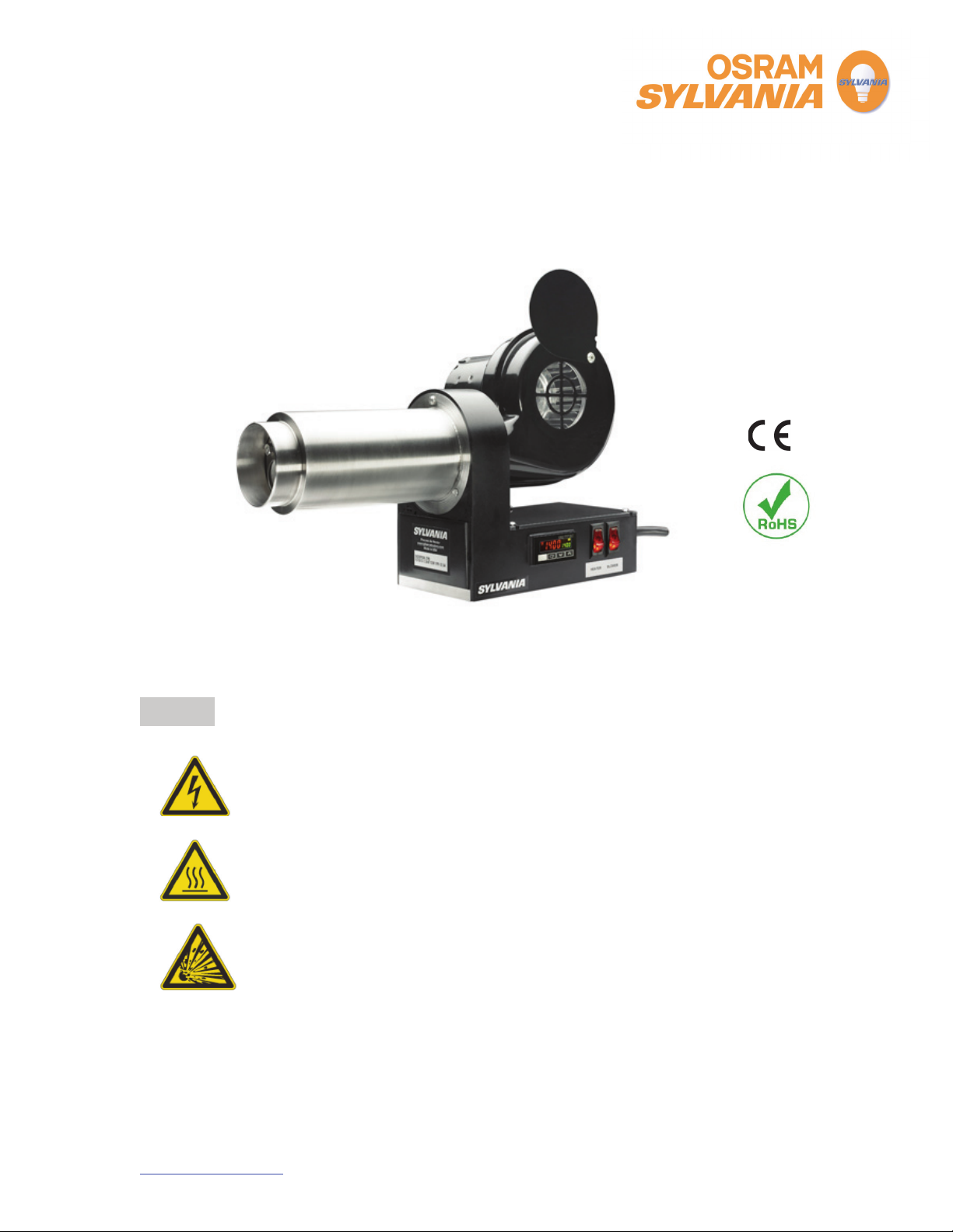
SKORPION™ Process Air Heater
SKORPION™ Process Air Heater
Safety
SHOCK HAZARD!
Only qualified individuals should install this heater and related controls.
Follow all applicable electrical codes and use proper wiring.
BURN HAZARD!
Avoid contact with the heater nozzle during or soon after operation.
EXPLOSION HAZARD!
Heater produces extremely high temperatures. Do not use in
hazardous environments, and/or near explosive or reactive gases,
or combustible materials.
OSRAM SYLVANIA
OSRAM SYLVANIA
OSRAM SYLVANIA
131 Portsmouth Avenue
131 Portsmouth Avenue
131 Portsmouth Avenue
Exeter, NH 03833 USA
Exeter, NH 03833 USA
Exeter, NH 03833 USA
+ 800-258-8290
+ 800-258-8290
800-258-8290
603-772-4331
603-772-4331
+
+
603-772-4331
603-772-1072
603-772-1072
,:
,:
: 603-772-1072
www.sylvaniaheaters.com
www.sylvaniaheaters.com
Page 2

OPERATING INSTRUCTIONS
06/01/2008
Description
The SKORPION™ Process Air Heater from OSRAM SYLVANIA represents the perfect
combination of power, size, reliability and control in Air Heating technology.
The SKORPION™ Process Air Heater produces air temperatures from 1200°F (650°C) (120V
version) to 1400°F (760°C) (230V version). A closed-loop PID temperature control system
ensures precise control of your process.
If used correctly, an element life of 5000 hours or greater can be expected.
Limited Warranty
OSRAM SYLVANIA Products Inc. (“OSPI”) warrants that this Product will be free of defects in material and
workmanship for a period of two (2) years from date of purchase. Buyer’s sole remedy, and OSPI’s sole
obligation, under this warranty is limited to (at OSPI’s option) repairing or replacing any non-conforming
Product or granting a credit to Buyer for the Product. A replacement Product assumes the remaining
warranty of the original Product. This warranty shall not apply to any Product that has been repaired or
altered, except by OSPI, or that has been subjected to abuse or mishandling. OSPI’s express warranty
applies only when the Product is properly operated in accordance with OSPI specifications and instructions.
THE FOREGOING CONSTITUTES THE SOLE AND EXCLUSIVE REMEDY OF BUYER. OSPI
DISCLAIMS ALL OTHER REPRESENTATIONS AND WARRANTIES, EXPRESS OR IMPLIED, WITH
RESPECT TO THE PRODUCT, INCLUDING THE IMPLIED WARRANTIES OF MERCHANTABILITY AND
FITNESS FOR A PARTICULAR PURPOSE. IN NO EVENT SHALL OSPI BE LIABLE FOR ANY SPECIAL,
INCIDENTAL OR CONSEQUENTIAL DAMAGES, INCLUDING LOST PROFITS OR REVENUES OR ANY
OTHER COSTS OR DAMAGES. SOME STATES DO NOT ALLOW LIMITATIONS ON HOW LONG AN
IMPLIED WARRANTY LASTS AND/OR DO NOT ALLOW THE EXCLUSION OF INCIDENTAL OR
CONSEQUENTIAL DAMAGES, SO THE ABOVE LIMITATIONS AND EXCLUSIONS MAY NOT APPLY.
To obtain service under this warranty, contact the place of purchase within two (2) years following date of
purchase. The following information must be provided in writing:
(i) Order number under which the Product was shipped;
(ii) Model/Serial Number; and
(iii) Reason for rejection.
Failure to follow this procedure shall void the warranty.
OSPI reserves the right (i) to examine the failed Product to determine the cause of failure and patterns of
usage and (ii) to be the sole judge as to whether the Product is defective and covered under this warranty.
The information contained in this manual is based on data considered to be true and accurate. Reasonable
precautions for accuracy has been taken in the preparation of this manual, however OSRAM SYLVANIA
assumes no responsibility for any omissions or errors, nor assumes any liability for damages that may result
from the use of the product in accordance with the information contained in this manual.
OSRAM SYLVANIA
131 Portsmouth Avenue
Exeter, NH 03833 USA
+ 800-258-8290
603-772-4331
+
603-772-1072
,:
www.sylvaniaheaters.com
1
Page 3
OPERATING INSTRUCTIONS
06/01/2008
Heater Models and Parts List
SKORPION™ AIR HEATERS REPLACEMENT PARTS
Complete Unit with Blower
F075615 1.5kW 120V~ 1 Ø 12.5A
F075616 3.0kW 230V~ 1 Ø 13A
F076008 4.5kW 230V~ 1 Ø 20A
Complete Unit without Blower*
F075869 1.5kW 120V~ 1 Ø 12.5A
F075835 3.0kW 230V~ 1 Ø 13A
F076029 4.5kW 230V ~ 1 Ø 20A
*SKORPION Models without Blower are supplied with a 1” NPT adaptor plate for separate
air source connection (<5 PSI).
Heating
Element
F205526 F205499 F205486 F205513 N/A F205494
F205502 F205499 F205486 F205512 N/A F205494
F205614 F205499 F205486 F205604 N/A F205494
F205526 F205499 F205486 N/A F205549 F205494
F205526 F205499 F205486 N/A F205549 F205494
F205614 F205499 F205486 N/A F205549 F205494
Temp
Control
SSR Power
Control
Blower
1” NPT
adaptor
plate
Nozzle
Tube
F075744 High Flow Nozzle 21mm (1”) diameter
F075745 Standard Flare 150mm x 12mm (6”x0.5”)
F075746 Wide Flare 300mm x 4mm (12”x 0.16”)
OSRAM SYLVANIA
131 Portsmouth Avenue
Exeter, NH 03833 USA
+ 800-258-8290
603-772-4331
+
603-772-1072
,:
www.sylvaniaheaters.com
ACCESSORIES
2
Page 4
OPERATING INSTRUCTIONS
06/01/2008
General Information
Environmental Conditions
Ambient Temperature 0°C to 38°C (32°F to 100°F)
Humidity 0% to 90% R.H.
Ambient Pressure 0.8 to 1.2 Bar (11.8 psia to 17.6 psia)
Ventilation
Use in a well-ventilated area away from excess dust, dirt, and moisture.
Cleaning
With unit OFF and unplugged, exterior surfaces
may be wiped clean using a damp cloth.
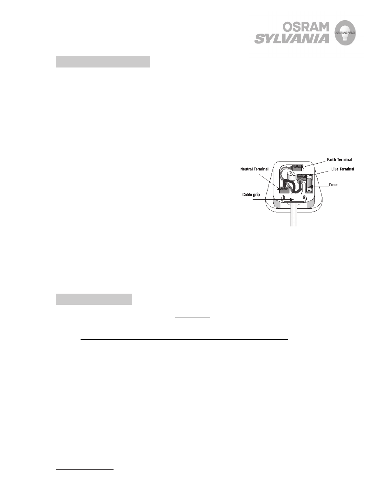
Attaching 230V (European style) plugs
(see diagram):
NOTE: Use plug appropriate for local area and codes.
Only qualified personnel should perform wiring.
Overcurrent protection should be provided external
to the heater unit within plug type shown or similar fusing.
Protective Earthing
The yellow and green ground wire in the power cable is attached directly to the aluminum
base plate inside the heater via a dedicated screw terminal. Additional protective earthing
can be attached to the aluminum base plate if desired.
Basic Operation
1. Turn SKORPION air heater ON using two switches:
1.1. Switch S1 (blower) sends power to the blower and to heater switch S2.
1.2. Switch S2 (heater) sends power to the heater control circuit.
1.3. Note, for heater safety, S2 (heater) cannot turn ON without S1 (blower) ON.
2. Adjust airflow via a rotational air damper at the blower inlet.
3. Adjust temperature set point with the UP/DOWN arrows on the temperature controller.
Heater will ramp to temperature.
3.1. The process temperature is measured with an internal type “K” thermocouple located at
the end of an element inside the stainless housing.
4. When turning the heater off the heater power (S2) may be turned off and the blower (S1)
left on to cool the heater housing assembly. This is suggested to prevent burn injury of
personnel around the heater but is not necessary for safety of the heater element.
OSRAM SYLVANIA
131 Portsmouth Avenue
Exeter, NH 03833 USA
+ 800-258-8290
603-772-4331
+
603-772-1072
,:
www.sylvaniaheaters.com
3
Page 5

OPERATING INSTRUCTIONS
06/01/2008
Detailed Operation
• Heater Voltage is regulated by a Solid State Relay (SSR), which is turned ON and OFF
rapidly according to the temperature controller DC OUT signal. A “zero cross” type SSR
is used to minimize electrical noise.
• Heater Element is protected with a resistive photo detector and a thermal resistor
(thermistor) mounted at the heater inlet. These sensors are connected in parallel with the
DC input signal going to the SSR.
o If the element overheats
(bright orange color) the photo detector resistance
decreases which reduces the control signal which, in turn, limits power to the
heater.
o If the air temperature in the housing reaches an unsafe level, the thermistor
resistance decreases which reduces the control signal, which in turn, limits power
to the heater.
o A small fixed resistor in series with the control signal sets element and air
temperature limits.
• The large black dots on the wiring diagram represent connections that are made on the
internal terminal strip. The terminal strip allows the customer easy access to remove and
replace the heater element and blower if necessary.
OSRAM SYLVANIA
131 Portsmouth Avenue
Exeter, NH 03833 USA
+ 800-258-8290
603-772-4331
+
603-772-1072
,:
www.sylvaniaheaters.com
4
Page 6

OPERATING INSTRUCTIONS
06/01/2008
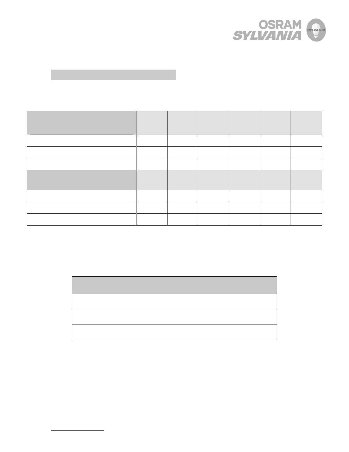
Performance
Heater Model 1.5kW 120V 3.0kW 230V 4.5kW 230V
MAXIMUM AIR TEMP
with exit restriction
Open ended/flare
High flow nozzle
At 20°C (68°F)
At 750°C (1400°F)
1000°F
(540°C)
1300°F
(730°C)
MAXIMUM FLOW RATE
no restriction, 60Hz power.
25 SCFM
(708 SLPM)
12 SCFM
(340 SLPM)
1400°F
(760°C)
1400°F
(760°C)
25 SCFM
(708 SLPM)
12 SCFM
(340 SLPM)
* FOR SKORPION models without Blower (external air source):
1400°F
(760°C)
1400°F
(760°C)
45 SCFM
(1274 SLPM)
22 SCFM
(623 SLPM)
Without
blower*
*see note
*see note
*see note
*see note
A) The maximum temperature capability of heater will depend entirely on the airflow rate
produced by external air source. Higher airflow rates than those produced by the standard
SKORPION blower will yield lower maximum temperatures.
B) External air supply must be turned ON prior to turning heater ON
C) For best flow conditions, use min. ” NPT size incoming air line.
D) Do not exceed 5 psi (.34 BAR) or air leaks will be noticeable in the heater.
OSRAM SYLVANIA
131 Portsmouth Avenue
Exeter, NH 03833 USA
+ 800-258-8290
603-772-4331
+
603-772-1072
,:
www.sylvaniaheaters.com
5
Page 7

OPERATING INSTRUCTIONS
06/01/2008
Replacement Procedures
I. Replacing the Heating Element
1. Turn heater/blower switches OFF, and disconnect from power source.
2. Use a flat screwdriver to remove (pry open) the wiring cover under the stainless nozzle
tube.
3. Remove the stainless nozzle by removing the two mounting screws, and the thru-bolt
which passes through the plastic support tower and threads into the nozzle flange.
4. Disconnect the KTC+ (Yellow), KTC- (Red), HTR1, HTR2 connections from the wiring
terminal as shown. Total of four wires.
5. Remove the old element, pulling the KTC and HTR wires through the plastic support
tower.
6. Install new element by reversing steps 2-5.
II. Replacing the Temperature Controller
1. Turn heater/blower switches OFF, and disconnect from power source.
2. Remove the four screws which secure the black plastic top cover plate.
3. Remove the four screws which attach the aluminum base plate to the main heater plastic
structure.
4. With the top cover plate and the aluminum plate removed, you now have access to the
top and bottom mounting tabs on the temperature controller.
5. While lifting the top and bottom white plastic mounting tabs, gently push the temperature
controller halfway out of the faceplate.
6. Using masking tape or other method, mark each wire going to the back of the controller
with a number 1-9, corresponding to its terminal location. This is CRITICAL to ensure
proper wiring to the new controller.
7. Using a small screwdriver, loosen and remove the wires from the terminals at the rear of
the temperature controller.
8. Remove temperature controller completely from the faceplate.
9. Install new temperature controller halfway into faceplate.
10. Reconnect the wires according to the terminal number and ID marking from step #4.
11. Press controller into faceplate while engaging the white mounting tab securely.
12. Replace the black plastic top cover plate and reattach mounting screws.
OSRAM SYLVANIA
131 Portsmouth Avenue
Exeter, NH 03833 USA
+ 800-258-8290
603-772-4331
+
603-772-1072
,:
www.sylvaniaheaters.com
6
Page 8

OPERATING INSTRUCTIONS
06/01/2008
III. Replacing the Power Controller
NOTE: Thermally conductive compound (“heat sink grease”) is required to mount new SSR.
1. Turn heater/blower switches OFF, and disconnect from power source.
2. Remove the four screws which secure the black plastic top cover plate.
3. Remove the four wires connecting to the four terminals on the solid state relay. Be sure
to mark the wires clearly for re-installation.
4. Remove the two screws holding the Solid State Relay from the aluminum base plate and
remove the SSR.
5. Carefully wipe off the old white heat sink putty from the base plate and apply new heat
sink putty on the back of the new SSR.
6. Mount SSR onto aluminum base plate with the mounting screws and reconnect wires.
7. Replace the black plastic top cover plate and reattach mounting screws.
IV. Replacing the Blower
1. Turn heater/blower switches OFF, and disconnect from power source.
2. Use a flat screwdriver to remove (pry open) the wiring cover under the stainless nozzle
tube.
3. Remove the blower by removing the three mounting bolts. One of these bolts passes
through the plastic support tower and threads into the nozzle flange.
4. Disconnect the GND, FAN1, and FAN2 connections from the wiring terminal as shown.
Total of three wires.
5. Remove the blower, GND, FAN1, FAN2 wires through the plastic support tower.
6. Install new blower by reversing steps 2-5.
OSRAM SYLVANIA
131 Portsmouth Avenue
Exeter, NH 03833 USA
+ 800-258-8290
603-772-4331
+
603-772-1072
,:
www.sylvaniaheaters.com
7
Page 9

OPERATING INSTRUCTIONS
06/01/2008
SKORPION™ (1.5kW/3.0kW)
OSRAM SYLVANIA
131 Portsmouth Avenue
Exeter, NH 03833 USA
+ 800-258-8290
603-772-4331
+
603-772-1072
,:
www.sylvaniaheaters.com
8
Page 10

OPERATING INSTRUCTIONS
06/01/2008
SKORPION™ (4.5kW)
OSRAM SYLVANIA
131 Portsmouth Avenue
Exeter, NH 03833 USA
+ 800-258-8290
603-772-4331
+
603-772-1072
,:
www.sylvaniaheaters.com
9
Page 11

OPERATING INSTRUCTIONS
06/01/2008
SKORPION™ Without Blower (1.5kW/3.0kW/4.5kW)
OSRAM SYLVANIA
131 Portsmouth Avenue
Exeter, NH 03833 USA
+ 800-258-8290
603-772-4331
+
603-772-1072
,:
www.sylvaniaheaters.com
10
Page 12

OPERATING INSTRUCTIONS
OPERATING INSTRUCTIONS
06/01/2 008
06/01/2 008
OSRAM SYLVANIA
OSRAM SYLVANIA
OSRAM SYLVANIA
131 Portsmouth Avenue
131 Portsmouth Avenue
131 Portsmouth Avenue
Exeter, NH 03833 USA
Exeter, NH 03833 USA
Exeter, NH 03833 USA
+ 800-258-8290
+ 800-258-8290
800-258-8290
603-772-4331
603-772-4331
+
+
603-772-4331
603-772-1072
603-772-1072
,:
,:
: 603-772-1072
www.sylvaniaheaters.com
www.sylvaniaheaters.com
 Loading...