

Sylvania DVL300D Service Manual

SERVICE MANUAL
This service manu al supplement (DVL300D) co ntains only
the difference from the original mode l.
For all other data, see the original service manual for
DVL100D.
DVD PLAYER
DVL300D

IMPORTANT SAFETY NOTICE
Proper service and repair is important to the safe, reliable operation of all
Funai Equipment. The service procedures recommended by Funai and
described in this service manual are effective methods of performing
service operations. Some of these service special tools should be used
when and as recommended.
It is important to note that this service manual contains vario us CAUTIONS
and NOTICES which should be carefully read in order to minimize the risk of
personal injury to service personnel. The possibility exists that improper
service methods may damage the equipment. It also is important to
understand that these CAUTIONS and NOTICES ARE NOT EXHAUSTIVE.
Funai could not possibly know, evaluate and advice the service trade of all
conceivable ways in which service might be done or of the possible
hazardous consequences of each way. Consequently, Funai has not
undertaken any such broad evaluation. Accordingly, a servicer who uses a
service procedure or tool which is not recommended by Funai must first
use all precautions thoroughly so that neither his safety nor the safe
operation of the equipment will be jeopardized by the service method
selected.
TABLE OF CONTENTS
OPERATING CONTROLS AND FUNCTIONS . . . . . . . . . . . . . . . . . . . . . . . . . . . . . . . . . . . . . . . . . . . . . . . . 1-1-1
CABINET DISASSEMBLY INSTRUCTIONS . . . . . . . . . . . . . . . . . . . . . . . . . . . . . . . . . . . . . . . . . . . . . . . . . .1-2-1
BLOCK DIAGRAMS. . . . . . . . . . . . . . . . . . . . . . . . . . . . . . . . . . . . . . . . . . . . . . . . . . . . . . . . . . . . . . . . . . . . . 1-3-1
SCHEMATIC DIAGRAMS / CBA’S AND TEST POINTS . . . . . . . . . . . . . . . . . . . . . . . . . . . . . . . . . . . . . . . . .1-4-1
LEAD IDENTIFICATIONS . . . . . . . . . . . . . . . . . . . . . . . . . . . . . . . . . . . . . . . . . . . . . . . . . . . . . . . . . . . . . . . . 1-5-1
EXPLODED VIEWS. . . . . . . . . . . . . . . . . . . . . . . . . . . . . . . . . . . . . . . . . . . . . . . . . . . . . . . . . . . . . . . . . . . . . 1-6-1
DIFFERENT PARTS FROM ORIGINAL MODEL (DVL100) . . . . . . . . . . . . . . . . . . . . . . . . . . . . . . . . . . . . . .1-7-1
Manufactured under license from Dolby Laboratories. "Dolby"
and the double-D symbol are trademarks of Dolby Laboratories.
y
g
h
nt
h
KLL
g
pause playback temporarily / frame-by-frame playback
]
]
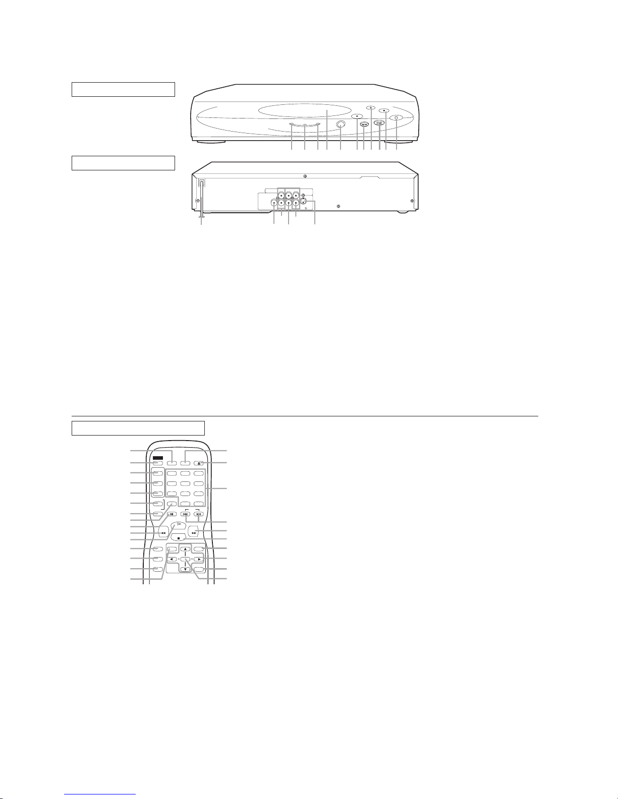
OPERATING CONTROLS AND FUNCTIONS
FRONT PANEL
POWER D ISC IN
PLAY
OPEN/CLOSE
PLAY
STOP
POWER
SKIP/SEARCH
REAR VIEW
1. POWER
to switch the player to ON or OFF
2. STOP
to stop playback
3. SKIP G / SEARCH
goes to next chapter or track during playback; press and
hold for 1.5 seconds for a forward search
4. PLAY
to start or resume disc playback
5. SKIP H / SEARCH
goes to previous chapter or track during playback; press
and hold for 1.5 seconds for a reverse search
6. OPEN/CLOSE
to open/close the disc tray
7. Remote Sensor window
8. Disc tray
9. DISC IN indicator
light appears when a disc is in the DVD player
10. PLAY indicator
y
REMOTE CONTROL
1
2
3
4
5
6
7
8
9
10
11
12
13
14
15
1. DISPLAY
to access or remove the display screen during DVD or
Audio CD playback
2. POWER
switch DVD player ON or OFF
3. AUDIO
to choose audio languages or sound modes
4. SUBTITLE
subtitle language DVD selector
5. ANGLE
select DVD camera angle
6. REPEAT
repeat chapter, track, title, all.
7. REPEAT A-B
repeat a specific segment
8. CLEAR
to reset the setting
9. PAUSE
POWER
AUDIO
TITLE
ANGLE
REPEAT
SETUP
MODE
ZOOM
DISPLAY
SUB
CLEAR
TITLE
12
g
h
OPEN/
SEARCH
CLOSE
MODE
123
456
789
0 +10
SKIPPAUSEA-B
PLAY
FWDREV
STOP
MENU
ENTER
RETURN
[Fig. 1
[Fig. 2
AUDIO OUT
DIGITAL AUDIO OUT
PCM / BITSTREAM
VIDEO
OUT
131415 17
YCr
16
16 357891011 4 2
COMPONENT
VIDEO OUT
S-VIDEO OUT
CbLRCOAXIAL
11. POWER indicator
lights when the power is on
12. MAIN (AC Power Cord)
connect to a standard AC outlet
13. COAXIAL (Digital audio out)
connect to AUDIO inputs of a digital (coaxial) audio
equipment
14. AUDIO OUT (Left/Right)
connect to AUDIO inputs of an amplifier, receiver or
stereo system
15. VIDEO OUT
connect to the Video Input of a TV.
16. COMPONENT VIDEO OUT
connect to a TV with Component video in jacks.
17. S-VIDEO OUT
connect to a TV with S-Video inputs
Caution: Do not touch the inner pins of the jacks on the
rear panel. Electrostatic discharge may cause permane
damage to the player.
10. REV
25
24
11. PLAY
12. SETUP
h
to view DVD picture in fast reverse motion
to start a DVD disc playback
to access or remove the DVD setup menu
13. MODE
23
to set up programmed or random playback (Audio CD)
to set the black level and virtual surround during DVD
playback
22
21
20
19
18
17
16
[Fig. 3]
14. ZOOM
enlarge DVD video image
15. TITLE
to display title menu of a disc
16. ENTER
acknowledge menu selection
17. RETURN
to return previous or remove setup menu
18. Arrow (sB
K
)
select an item in the menu
19. MENU
to display the menu of the DVD disc
20. STOP
to stop a DVD disc playback
21. FWD
g
to view DVD picture in fast forward motion
22. SKIP H,G
to skip chapter/tracks
23. 0-9 Number buttons
select numbered items in a menu
+10
use this button to enter number 10 and above
24. OPEN/CLOSE
to open/close the disc tray
25. SEARCH MODE
to locate a desired point
1-1-1 E5760IB
CABINET DISASSEMBLY INSTRUCTIONS
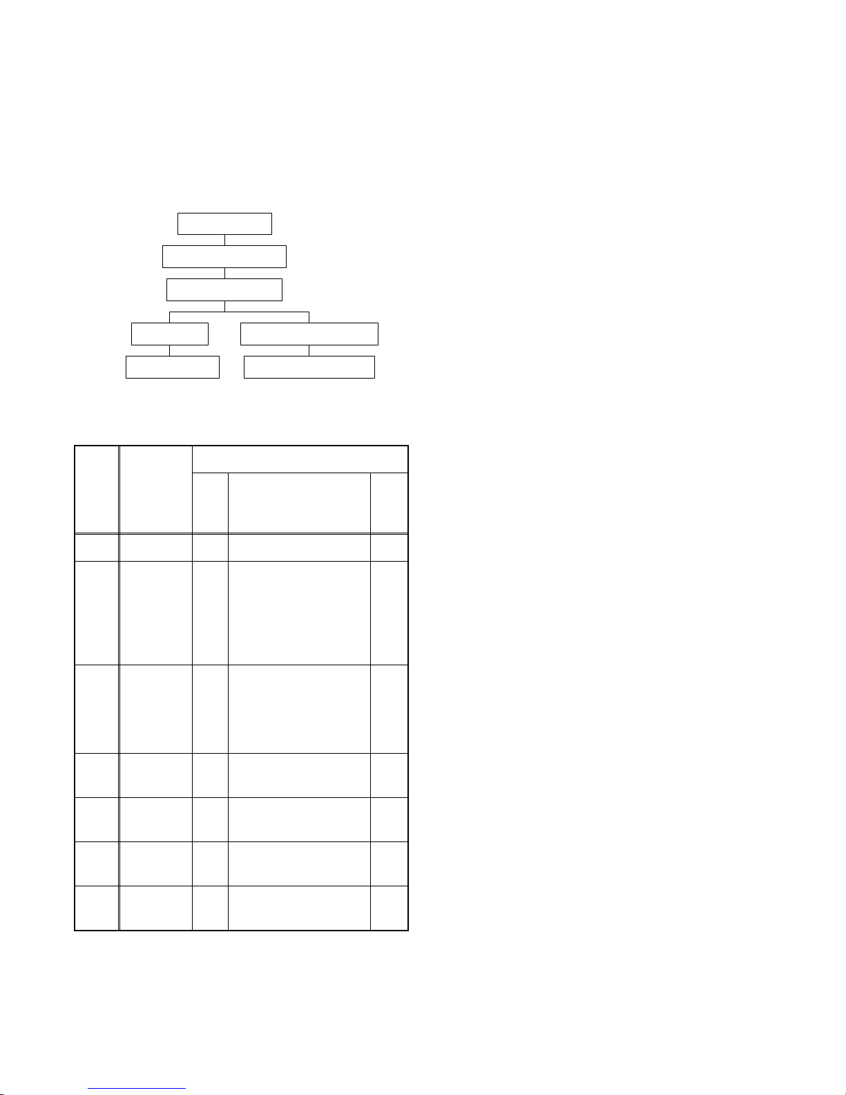
1. Disassembly Flowchart
This flowchart indicates the disassem bly steps to gain
access to item(s) to be serviced. When reassembling,
follow the steps in reverse order. Bend, route, and
dress the cables as they were originally.
[1] Top Cover
[2] Front Assembly
[3] DVD Mecha
[5] DVD Main CBA Unit[4] AV CBA
[7] Main CBA Holder[6] Rear Panel
2. Disassembly Method
REMOVAL
ID/
LOC.
No.
[1] Top Cover D1 5(S-1) -
[2]
[3]
[4] AV CBA D5
[5]
[6]
[7]
PART
Front
Assembly
DVD
Mecha
DVD Main
CBA Unit
Rear
Panel
Main CBA
Holder
REMOVE/*UNHOOK/
Fig.
UNLOCK/RELEASE/
No.
UNPLUG/DESOLDER
*2(L-1), Tray Panel,
D2
*2(L-2), *5(L-3)
D3,D43(S-2), *CN201,
*CN301
4(S-3), 3(S-4),
*CN1001, *CN1601
D5 2(S-5) -
D6 3(S-6) -
D6 (S-7) -
Note
1-1
1-2
1-3
1-4
1-5
1-6
2
2-1
2-2
2-3
3
-
(1): Identification (location) No. of parts in the figures
(2):Name of the part
(3):Figure Number for reference
(4): Identification of parts to be removed, unhooked,
unlocked, released, unplugged, unclamped, or
desoldered.
P=Spring, L=Locking Tab, S=Screw,
CN=Connector
*=Unhook, Unlock, Release, Unplug, or Desolder
e.g. 2(S-2) = two Screws (S-2),
2(L-2) = two Locking Tabs (L-2)
(5):Refer to “Reference Notes.”
Reference Notes
CAUTION 1: Locking Tabs (L-1), (L-2) and (L-3) are
fragile. Be careful not to break them.
1-1. Connect the wall plug to an AC outlet and pres s
the OPEN/CLOSE button to open the Tray.
1-2. Remove the Tray Panel by releasing two Locking
Tabs (L-1).
1-3. Press the OPEN/CLOSE button again to close
the Tray.
1-4. Press the POWER button to turn the power off.
1-5. Unplug an AC cord.
1-6. Release two Locking Tabs (L-2). Then, release
five Locking Tabs (L-3) (to do this, first release
two Locking Tabs (A) at the side, and then three
Locking Tabs (B) at the bottom.)
CAUTION 2: Electrostatic breakdown of the laser
diode in the optical system block may occur as a
potential difference caused by electrostatic charge
accumulated on cloth, human body etc, during
unpacking or repair work.
To avoid damage of pickup follow next procedures.
2-1. Slide out the pickup unit as shown in Fig. D4.
2-2. Short the three short lands of FPC cable with sol-
der before removing the FFC cable (CN201) from
it. If you discon nect the FFC cable (CN201), the
laser diode of pickup will be destroyed. (Fig. D4)
2-3. Disconnect Connector (CN301). Remove three
Screws (S-2) and lift the DVD Mecha. (Fig. D3)
CAUTION 3: When reassembling, confirm the FFC
cable (CN201) is connec ted completely. Then remove
the solder from the three short lands of FPC cable.
(Fig. D4)
↓
(1)
↓
(2)
↓
(3)
↓
(4)
↓
(5)
1-2-1 E5760DC
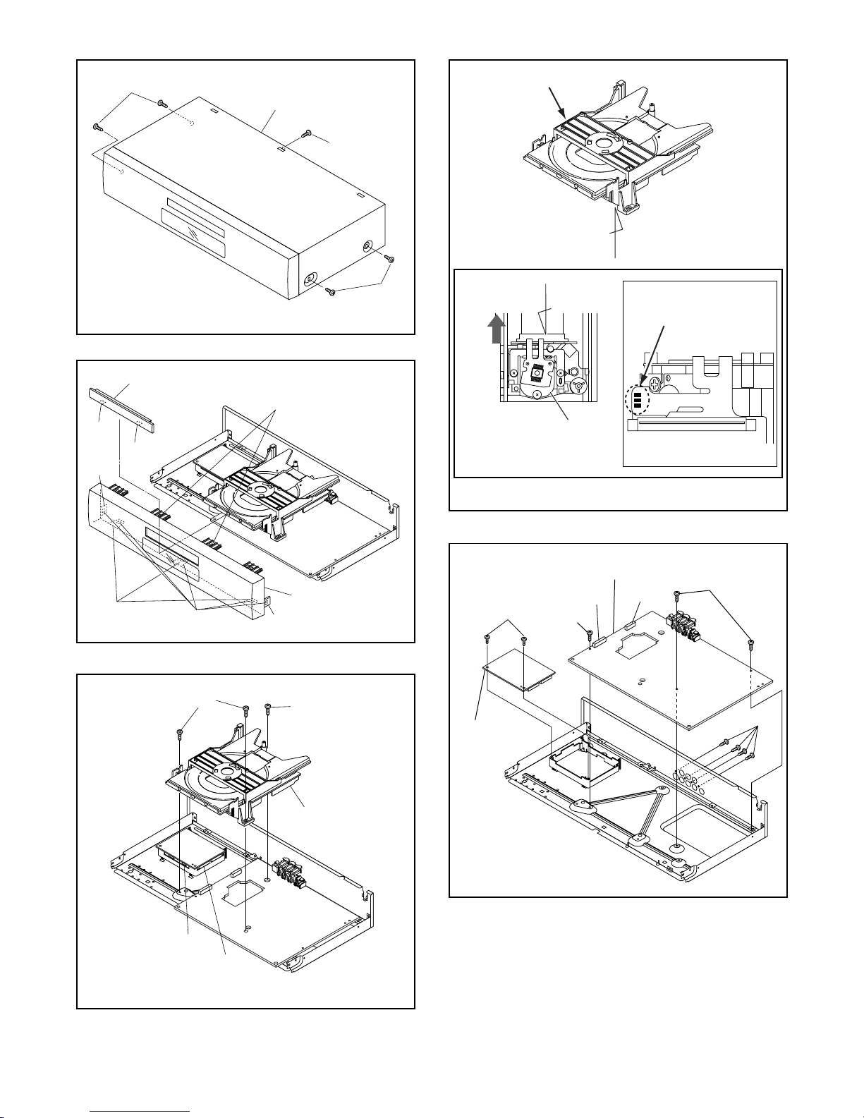
)
(S-1)
4
DVD Mecha
[1] Top Cover
(S-1)
A
(L-1)
(A)
(B)
Tray Panel
(L-1)
(L-3)
(L-2)
[2] Front Assembly
(A)
(S-1
Fig. D1
Fig. D2
Slide
B
Pickup Unit
View for A
(S-5)
[4] AV CBA
CN1001
(S-4)
Short the three short
lands by soldering
View for B
CN1601
Fig. D
(S-4)
(S-2)
[3] DVD Mecha
CN301
CN201
(S-2)
[5] DVD Main
CBA Unit
(S-3)
Fig. D5
Fig. D3
1-2-2 E5760DC
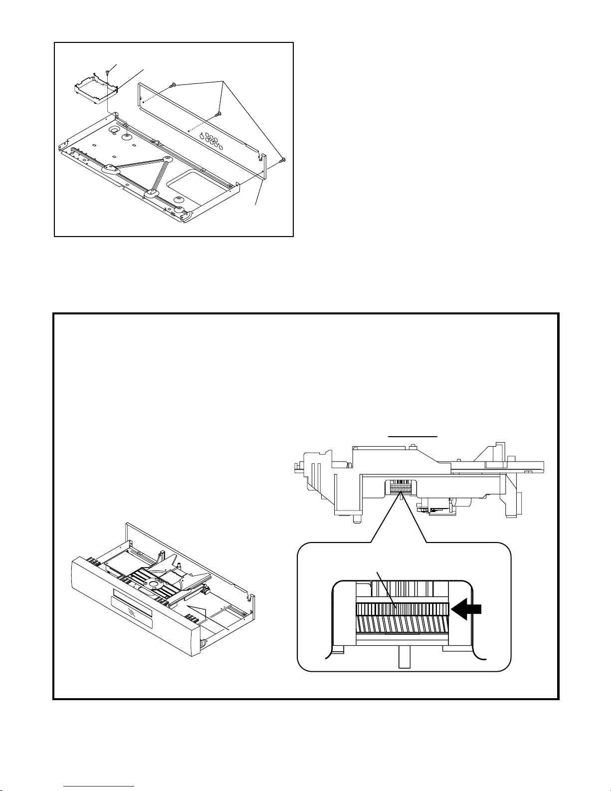
(S-8)
[7] Holder
(S-7)
[6] Rear Panel
Fig. D6
HOW TO MANUAL EJECT
1. Remove the Top Case.
2. Rotate the roulette in the direction of the arrow as
shown below.
View for A
Rotate this roulette in
the direction of the arrow
A
1-2-3 E5760DC
 Loading...