

Sylvania D6 Installation Manual
WARNING
!
NOTICE
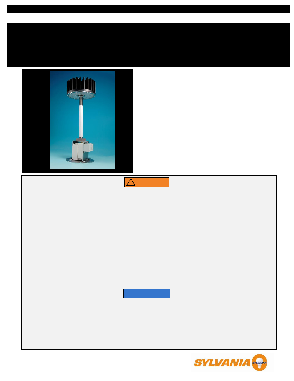
The D6 Area Light LED Retrofit Kit from SYLVANIA is an
alternative to high-intensity discharge (HID) lamps up to 175W
at pole heights up to 30 feet. The directional light distribution of
high power LEDs allows the delivery of light only where
needed, reducing wasted light and minimizing light trespass
and upward emissions. The D6 is an environmentally friendly
lighting solution as it contains no mercury or lead. It is an
excellent solution for communities that wish to convert their
existing lighting systems as it offers substantial energy and
maintenance cost savings as well as minimizes waste in
landfills.
RETRO0018 07/10
www.sylvania.com
D6 Area Light LED Retrofit Kit
INSTALLATION GUIDE
TO PREVENT PERSONAL INJURY OR PRODUCT DAMAGE ONLY LICENSED ELECTRICIANS SHOULD PROVIDE ALL INSTALLATION
SERVICES.
FAILURE TO INSTALL THIS PRODUCT IN ACCORDANCE WITH THE NATIONAL ELECTRIC CODE (NEC), OR THE CANADIAN
ELECTRICAL CODE (CSA 22.1), ALL APPLICABLE FEDERAL, STATE AND LOCAL ELECTRIC CODES AS WELL AS THE SPECIFIC
UNDERWRITERS LABORATORIES (UL) SAFETY STANDARDS FOR THE INSTALLATION, LOCATION AND APPLICATION MAY CAUSE
UNSAFE SITUATIONS LEADING TO SERIOUS PERSONAL INJURY, DEATH, PROPERTY DAMAGE AND/OR PRODUCT MALFUNCTION.
TO AVOID ELECTRIC SHOCK OR COMPONENT DAMAGE DISCONNECT POWER BEFORE ATTEMPTING INSTALLATION OR
SERVICING.
INSTALLATION MUST BE STRUCTURALLY SOUND AS TO PREVENT DAMAGE OR PERSONAL INJURY DUE TO FIXTURE COLLAPSE.
USE CAUTION WHEN HANDLING THIS PRODUCT DURING OR AFTER OPERATION AS IT MAY BECOME HOT AND CAUSE BURNS.
DISCONNECT PRODUCT AND ALLOW COOLING PRIOR TO SERVICING.
ANY ALTERATION OR MODIFICATION OF THIS PRODUCT IS EXPRESSLY FORBIDDEN AS IT MAY CAUSE SERIOUS PERSONAL
INJURY, DEATH, PROPERTY DAMAGE AND/OR PRODUCT MALFUNCTION.
TO PREVENT PRODUCT MALFUNCTION AND / OR ELECTRICAL SHOCK THIS PRODUCT MUST BE PROPERLY GROUNDED.
DO NOT MAKE OR ALTER ANY OPEN HOLES IN AN ENCLOSURE OF WIRING OR ELECTRICAL COMPONENTS DURING KIT
INSTALLATION.
TO PREVENT WIRING DAMAGE OR ABRASION, DO NOT EXPOSE WIRING TO EDGES OF SHEET METAL OR OTHER SHARP
OBJECTS.
TO PREVENT RISK OF FIRE OR ELECTRIC SHOCK. INSTALL THIS KIT ONLY IN THE LUMINARIES THAT HAVE THE CONSTRUCTION
FEATURES AND DIMENSIONS SHOWN IN THE PHOTOGRAPHS AND/OR DRAWINGS.
Above image of 55W model.
PLEASE READ ALL INSTRUCTIONS BEFORE ATTEMPTING INSTALLATION
This device complies with part 15 of the FCC Rules. Operation is subject to the following two conditions: (1) This device may not cause
harmful interference, and (2) this device must accept any interference received, including interference that may cause undesired operation.
Even though this product may continue to light after the lens is cracked or broken, or after the specified lifetime has passed, it must be
replaced in order to maintain appropriate light levels.
Failure of fixture to provide sufficient weather protection voids warranty.
To prevent early product failure, this product should be installed in operating environments with maximum mean ambient operating
temperature for LED Retrofit Module: 104°F (40C); maximum ambient operating temperature cannot exceed 140°F (60°C).
Installation requirements may vary depending on the luminaire retrofitted.
Incorrect electrical polarity may damage the module.
If installed in fixture other than acorn or shoebox, contact UL customer service department at (877) 854-3577 to certify retrofitted fixture.
Item
Number
Ordering
Abbreviation
Wattage (W)
Input Voltage
(VAC)
Light
Distribution
78628
LED55RETROFIT/750/T5M/D6
55
120-277
Type-V Medium
78629
LED55RETROFIT/756/T5S/D6
55
120-277
Type-V Short
78630
LED55RETROFIT/750/T3M/D6
55
120-277
Type-III Medium
78631
LED55RETROFIT/756/T3S/D6
55
120-277
Type-III Short
78645
LED55RETROFIT/741/T5M/D6
55
120-277
Type-V Medium
78646
LED35RETROFIT/750/T5M/D6
35
120-277
Type-V Medium
78647
LED35RETROFIT/741/T5M/D6
35
120-277
Type-V Medium
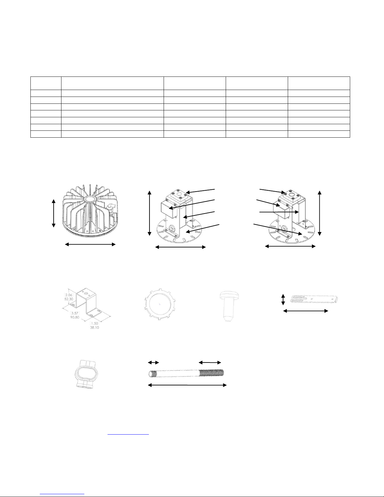
PART-C (1x)*
Top Bracket
PART-E (8x)
#8 Screws (extra 4x
supplied)
PART-F (4x)
Side Bracket
5.8”
[148 mm]
1.1”
[29mm]
PART-G (2x)
3M Connectors
PART-H (1x)
Mounting Pole
12”
[165 mm]
½” NPT
½” NPSM 4” long
PART-D (1x)
½” Locknut
PART-B: 35W Model (1x)
Power Supply Assembly
6.2”
[157mm]
Insulation Block
Surge Protector
Adapter Disk
6.5”
[165 mm]
Power Supply (s)
PART-B: 55W Model (1x)
Power Supply Assembly
6.5”
[165 mm]
6.2”
[157mm]
Required Tools and Hardware (Not
provided)
Flat and Phillips Head Screwdriver;
Pliers; Wire strippers; Wire connectors
(wire Nuts)
PART-A (1x)
LED Light Engine
6.8”
[172 mm]
3.7”
[95 mm]
1. PRODUCT OVERVIEW
1.1. Products Covered
1.2. D6 LED Retrofit Kit Product Description
Notes:
Product has been properly packed to protect during transit. Unpack, inspect, and notify the distributor or shipping agent of any damage found.
For additional information visit www.sylvania.com or call 1-800-LIGHTBULB (1-800-544-4828)
* PART-B (Power Supply Assembly) displayed is for the 55W model. 35W model contains only one power supply.
* PART-C (Top Bracket) may be used to mount unit from top, if desired. Reference designs can be found at mySylvania.com.
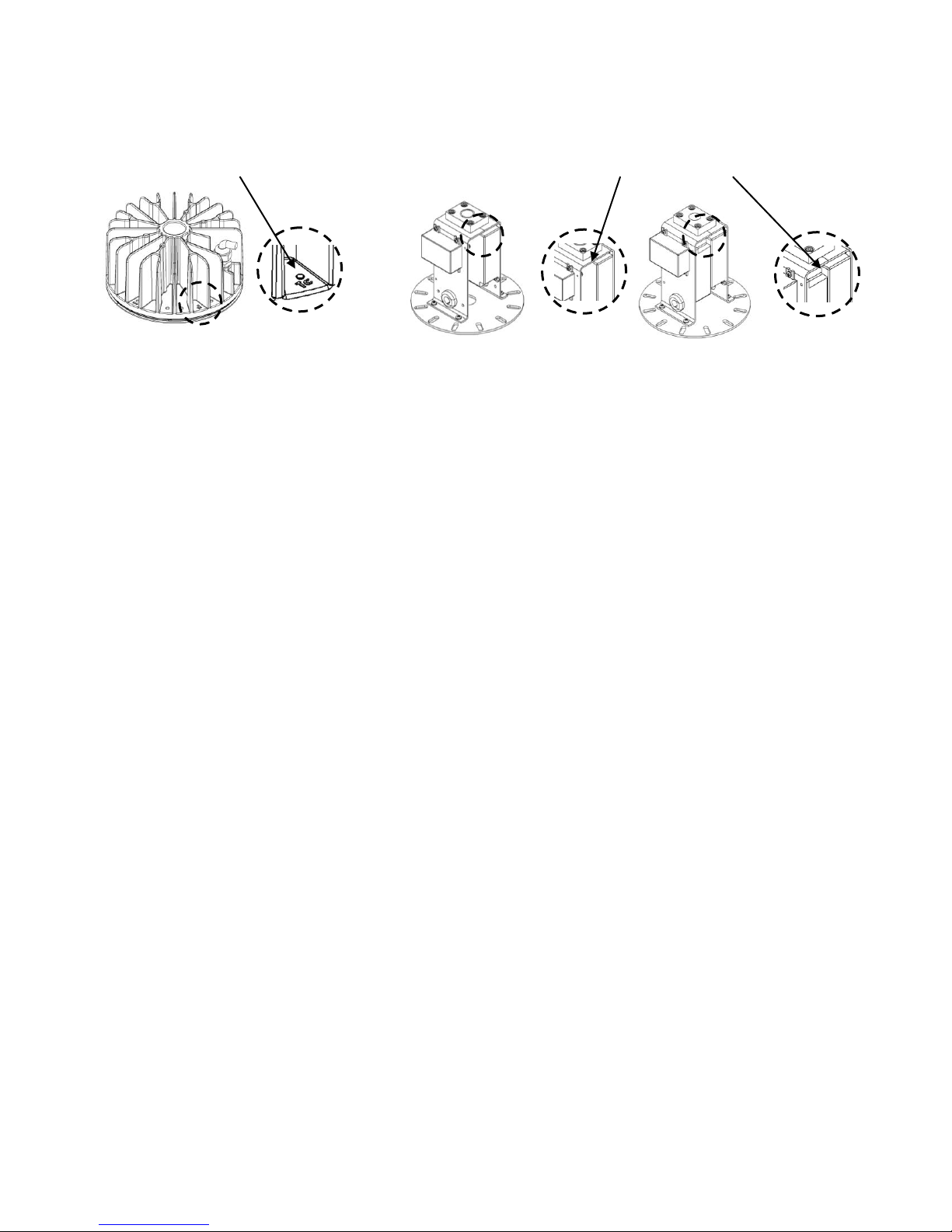
1.3. Fixture Considerations
LED Light Engine
Tc Point < 75C
Power Supply Assembly
Tc Point < 80C
35W Models
55W Models
Note:
Please contact your Sylvania representative for reference design of the mounting hardware.
1.4. Maintenance and Cleaning
Periodic cleaning of fixture will ensure operation at maximum optical efficiency
Refer to fixture installation instructions for maintenance and cleaning guidelines
Even though LED Retrofit Kit may continue to light after the specified lifetime has passed, it must be replaced in order to maintain
appropriate light levels
2. INSTALLATION INSTRUCTIONS
Note: Minimum total fixture dimensions
Height
Width at Largest Diameter
Bottom Opening
20”
9”
7.5”
Note: Minimum total fixture dimensions
Width
Depth
Height
12”
17 1/8”
6”
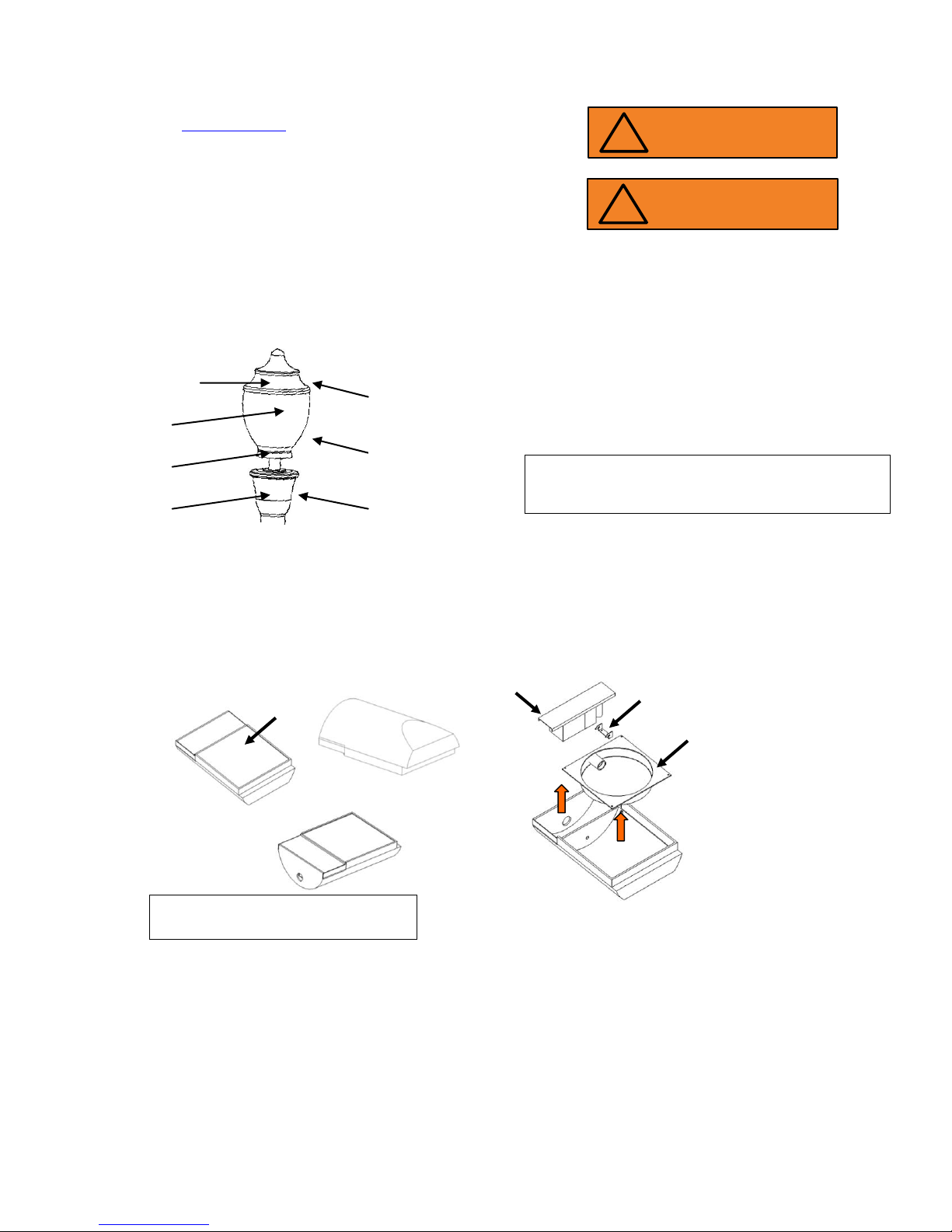
SHOEBOX
Original Ballast
Reflector Housing
Ballast Hinge
Bracket
Fixture Cover
Remove:
Fixture cover
Original ballast
Reflector housing
Ballast hinge bracket*
*Save all mounting screws
Original optical
components
(reflectors)
Fixture Dome Top
Ballast
Socket
Lamp
Fixture Base
Fixture Globe
WARNING
!
Risk of electric shock
Disconnect power before servicing
WARNING
!
Risk of burn
Allow unit to cool fully before servicing
POST-TOP
Note: Failure to remove original components
including ballast will void product warranty.
* Refer to fixture installation manual for fixture mounting procedures
** Please refer to www.Sylvania.com for additional installation instructions
2.1. STEP 1: Prepare fixture for installation
Turn power off before attempting installation
Remove lamp, original optical components, socket, and ballast
If photocell-controlled, connect unit after external control
 Loading...