

Page 1
ATSC STB
As an ENERGY STAR
®
Partner, our company has
determined that this product
meets the E
NERGY STAR
®
guidelines for energy efficiency.
E
NERGY STAR
®
is a U.S. registered mark.
OWNER’S
MANUAL
If you need additional assistance for set-up or operating
after reading owner’s manual, please call
TOLL FREE : 1-800-968-3429.
Or visit our WEB SITE at http://www.funai-corp.com
Please read before using this equipment.
6900DTE
INSTRUCCIONES EN ESPAÑOL INCLUIDAS.
Page 2

Table of Contents
1 Before Using . . . . . . . . . . . . . . . . . 3
Important Safeguards. . . . . . . . . . . . . . . 3
Precautions . . . . . . . . . . . . . . . . . . . . . . 5
Information on digital broadcasting . . . . 6
Major features of STB . . . . . . . . . . . . . . 7
Location of controls. . . . . . . . . . . . . . . . 8
Accessories . . . . . . . . . . . . . . . . . . . . . . 10
Installing batteries . . . . . . . . . . . . . . . . . 10
2 Antenna Connections . . . . . . . . . . 11
Connecting the Smart Antenna. . . . . . . . 11
Connecting a different antenna. . . . . . . . 12
CHANNEL
Adding/Deleting channels . . . . . . . . . . . 35
Adjusting antenna . . . . . . . . . . . . . . . . . 38
Receiving channels . . . . . . . . . . . . . . . . 39
DISPLAY
Selecting screen formats
(Screen ratio and Display mode) . . . . . . 41
CLOCK
Setting the clock . . . . . . . . . . . . . . . . . . 44
DETAIL
V-CHIP options . . . . . . . . . . . . . . . . . . . 47
Closed caption options. . . . . . . . . . . . . . 56
Choosing the screen language . . . . . . . . 60
Choosing sound effects . . . . . . . . . . . . . 61
3 TV/Monitor Connections . . . . . . . . 14
STB connection using DVI-D HDCP OUT
jack to HDTV . . . . . . . . . . . . . . . . . . . . 14
STB connection using COMP. OUT jacks
to HDTV
. . . . . . . . . . . . . . . . . . . . . . . . 16
STB connection using S-VIDEO OUT or
CVBS OUT (Composite) jack to SDTV. . 18
4Other Connections. . . . . . . . . . . . . 19
STB connection to a decoder with
Dolby Digital. . . . . . . . . . . . . . . . . . . . . 19
STB connection to a standard stereo
system . . . . . . . . . . . . . . . . . . . . . . . . . . 20
STB connection to TV and Video device
(VCR, DVD recorder, etc.) . . . . . . . . . . 21
5Initial Setups (Setup Wizard) . . . . . 22
Initial setup . . . . . . . . . . . . . . . . . . . . . . 22
6Basic Operation . . . . . . . . . . . . . . . 25
Watching TV . . . . . . . . . . . . . . . . . . . . . 25
Channel banner . . . . . . . . . . . . . . . . . . . 27
Choosing audio and language . . . . . . . . 29
Picture Still . . . . . . . . . . . . . . . . . . . . . . 30
On screen messages. . . . . . . . . . . . . . . . 31
8 Others . . . . . . . . . . . . . . . . . . . . . . 62
Troubleshooting. . . . . . . . . . . . . . . . . . . 62
Specifications . . . . . . . . . . . . . . . . . . . . 64
Glossary and Acronyms. . . . . . . . . . . . . 64
Indice
9Guía rápida en español . . . . . . . . . 66
Antes de utilizar . . . . . . . . . . . . . . . . . . 66
Conexiones de antena . . . . . . . . . . . . . . 67
Conexiones de TV/Monitor . . . . . . . . . . 67
Otras conexiones . . . . . . . . . . . . . . . . . . 68
Ajustes iniciales (Asistente de ajuste) . . 69
Warr anty . . . . . . . . . . . . . . . . . . . . .
Back Cover
7Advanced Operation . . . . . . . . . . . 32
Electronic Program Guide (EPG). . . . . . 32
Setup menu options . . . . . . . . . . . . . . . . 34
2
EN
1A23
Page 3
WARNING: TO REDUCE THE RISK OF FIRE OR ELECTRIC SHOCK, DO NOT EXPOSE THIS APPLIANCE
TO RAIN OR MOISTURE.
CAUTION
RISK OF ELECTRIC SHOCK
DO NOT OPEN
THIS SYMBOL INDICATES THAT DANGEROUS VOLTAGE CONSTITUTING A
RISK OF ELECTRIC SHOCK IS PRESENT
WITHIN THIS UNIT.
1 Before
Using
CAUTION:
TO REDUCE THE RISK OF ELECTRIC SHOCK,
DO NOT REMOVE COVER (OR BACK). NO USER
SERVICEABLE PARTS INSIDE. REFER SERVICING
TO QUALIFIED SERVICE PERSONNEL.
The caution marking is located on the rear of the cabinet.
IMPORTANT SAFEGUARDS
1.Read instructions-All the safety and operating instructions
should be read before the appliance is operated.
2.Retain Instructions-The safety and operating instructions
should be retained for future reference.
3.Heed Warnings-All warnings on the appliance and in the
operating instructions should be adhered to.
4.Follow Instructions-All operating and use instructions
should be followed.
5.Cleaning-Unplug this product from the wall outlet before
cleaning. Do not use liquid cleaners or aerosol cleaners. Use
a damp cloth for cleaning.
EXCEPTION: A product that is meant for uninterrupted
service and, that for some specific reason, such as the possibility of the loss of an authorization code for a CATV converter, is not intended to be unplugged by the user for cleaning or any other purpose, may exclude the reference to
unplugging the appliance in the cleaning description otherwise required in item 5.
6.Attachments-Do not use attachments not recommended by
this product manufacturer as they may cause hazards.
7.Water and Moisture-Do not use this product near water-for
example, near a bath tub, wash bowl, kitchen sink, or laundry tub, in a wet basement, or near a swimming pool, and
the like.
8.Accessories-Do not place this product on an unstable cart,
stand, tripod, bracket, or table. This product may fall, causing serious injury to someone, and serious damage to the
appliance. Use only with a cart, stand, tripod, bracket, or
table recommended by the manufacturer, or sold with this
product. Any mounting of the appliance should follow the manufacturer’s instructions and should use a
mounting accessory recommended
by the manufacturer. An appliance
and cart combination should be
moved with care.
Quick stops, excessive force, and
uneven surfaces may cause the
appliance and cart combination to
overturn.
THIS SYMBOL INDICATES THAT THERE
ARE IMPORTANT OPERATING AND
MAINTENANCE INSTRUCTIONS IN THE
LITERATURE ACCOMPANYING THE
APPLIANCE.
AMEUBLES- Cet appareil ne doit être
placé que sur un meuble (avec ou sans
roulettes) recommandé par le fabricant.
Si vous l’installez sur un meuble à
roulettes, déplacez les deux ensembles
avec précaution. Un arrêt brusque, l’utilisation d’une force excessive et des surfaces irrégulières
risquent de déstabiliser l’ensemble et de le renverser.
9. Ventilation-Slots and openings in the cabinet and the back
or bottom are provided for ventilation and to ensure reliable
operation of this product and to protect it from overheating,
and these openings must not be blocked or covered. The
openings should never be blocked by placing this product
on a bed, sofa, rug, or other similar surface. This product
should never be placed near or over a radiator or heat register. This product should not be placed in a built-in installation such as a bookcase or rack unless proper ventilation is
provided or the manufacturer’s instructions have been
adhered to.
10.Power Sources-This product should be operated only from
the type of power source indicated on the marking label. If
you are not sure of the type of power supply to your home,
consult your appliance dealer or local power company. For
this products intended to operate from battery power, or
other sources, refer to the operating instructions.
11.Grounding or Polarization-This product is equipped with
a polarized alternating-current line plug(a plug having one
blade wider than the other). This plug will fit into the
power outlet only one way. This is a safety feature. If you
are unable to insert the plug fully into the outlet, try reversing the plug. If the plug should still fail to fit, contact your
electrician to replace your obsolete outlet. Do not defeat the
safety purpose of the polarized plug.
12.Power-Cord Protection-Power-supply cords should be
routed so that they are not likely to be walked on or
pinched by items placed upon or against them, paying particular attention to cords at plugs, convenience receptacles,
and the point where they exit from the appliance.
EN
1A23
3
Page 4
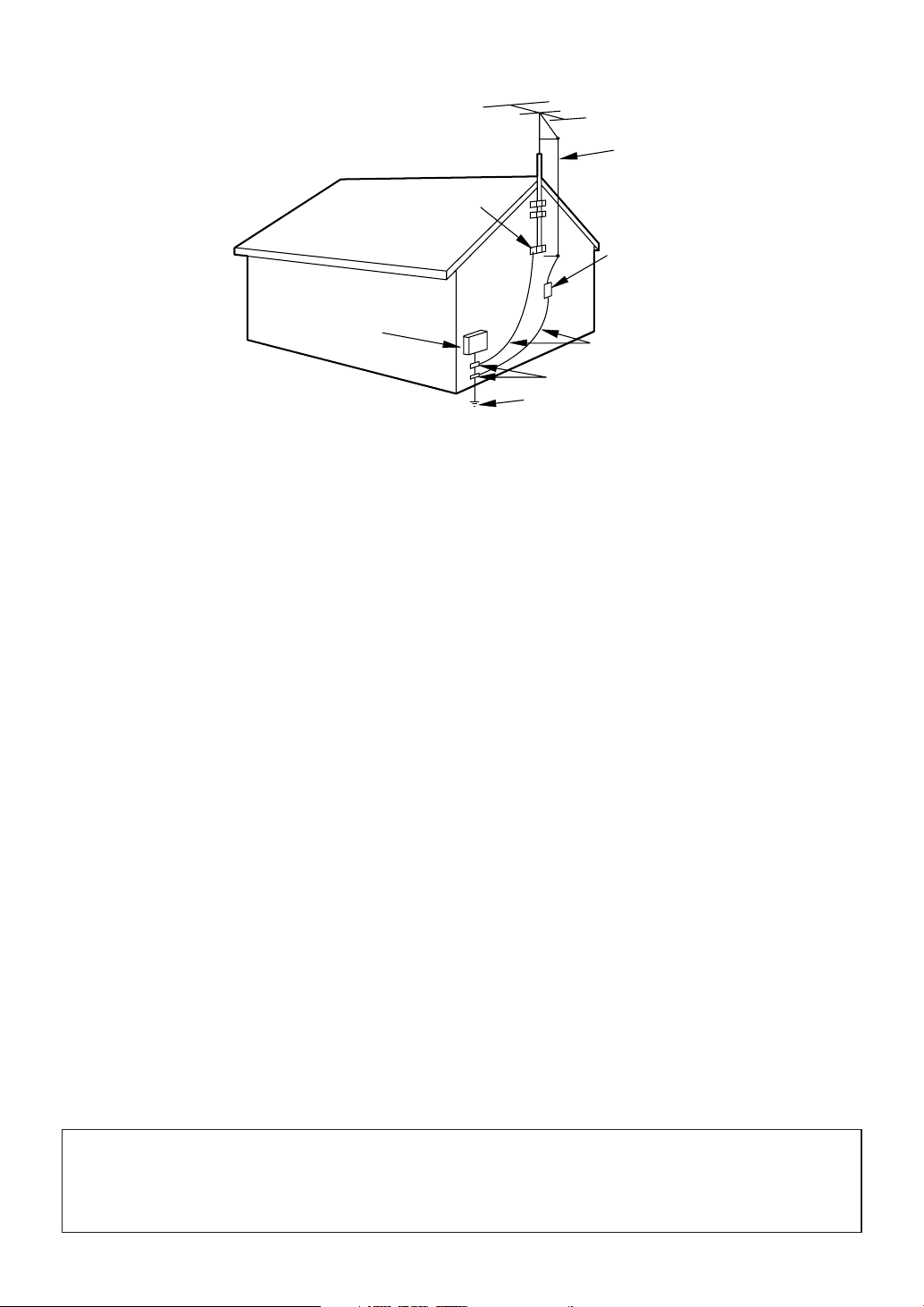
EXAMPLE OF ANTENNA GROUNDING AS PER
NATIONAL ELECTRICAL CODE
S2898A
FIGURE A
ELECTRIC
SERVICE
EQUIPMENT
NEC - NATIONAL ELECTRICAL CODE
GROUND
CLAMP
ANTENNA
LEAD IN
WIRE
ANTENNA
DISCHARGE UNI T
(NEC SECTION 810-20)
GROUNDING CONDUCTORS
(NEC SECTION 810-21)
GROUND CLAMPS
POWER SERVICE GROUNDI NG
ELECTRODE SYSTEM
(NEC ART 250, PART H)
13.Outdoor Antenna grounding-If an outside antenna or
cable system is connected to this product, be sure the
antenna or cable system is grounded so as to provide some
protection against voltage surges and built-up static
charges. Article 810 of the National Electrical Code,
ANSI/NFPA No. 70, provides information with respect to
proper grounding of the mast and supporting structure,
grounding of the lead-in wire to an antenna discharge unit,
size of grounding conductors, location of antenna-discharge
unit, connection to grounding electrodes, and requirements
for the grounding electrode. (Fig. A)
14.Lightning-For added protection for this product receiver
during a lightning storm, or when it is left unattended and
unused for long periods of time, unplug it from the wall
outlet and disconnect the antenna or cable system. This will
prevent damage to this product due to lightning and powerline surges.
15.Power Lines-An outside antenna system should not be
located in the vicinity of overhead power lines or other
electric light or power circuits, or where it can fall into
such power lines or circuits. When installing an outside
antenna system, extreme care should be taken to keep from
touching such power lines or circuits as contact with them
might be fatal.
16.Overloading-Do not overload wall outlets and extension
cords as this can result in a risk of fire or electric shock.
17.Object and Liquid Entry-Never push objects of any kind
into this product through openings as they may touch dangerous voltage points or short out parts that could result in
a fire or electric shock. Never spill liquid of any kind on
this product.
18.Servicing-Do not attempt to service this product yourself
as opening or removing covers may expose you to dangerous voltage or other hazards. Refer all servicing to qualified service personnel.
19.Damage Requiring Service-Unplug this product from the
wall outlet and refer servicing to qualified service personnel under the following conditions:
a. When the power-supply cord or plug is damaged or frayed.
b. If liquid has been spilled, or objects have fallen into this
product.
c. If this product has been exposed to rain or water.
d. If this product does not operate normally by following the
operating instructions. Adjust only those controls that are
covered by the operating instructions, as improper adjustment of other controls may result in damage and will often
require extensive work by a qualified technician to restore
this product to its normal operation.
e. If this product has been dropped or damaged in any way.
f. When this product exhibits a distinct change in perfor-
mance-this indicates a need for service.
20.Replacement Parts-When replacement parts are required,
be sure the service technician has used replacement parts
specified by the manufacturer that have the same characteristics as the original part. Unauthorized substitutions may
result in fire, electric shock, injury to persons or other hazards.
21.Safety Check-Upon completion of any service or repairs to
this product, ask the service technician to perform routine
safety checks to determine that this product is in proper
operating condition.
22.Heat-This product should be situated away from heat
sources such as radiators, heat registers, stoves, or other
products (including amplifiers) that produce heat.
CAUTION:TO PREVENT ELECTRIC SHOCK, MATCH WIDE BLADE OF PLUG TO WIDE SLOT, FULLY
INSERT.
ATTENTION: POUR ÉVITER LES CHOC ÉLECTRIQUES, INTRODUIRE LA LAME LA PLUS LARGE DE
LA FICHE DANS LA BORNE CORRESPONDANTE DE LA PRISE ET POUSSER JUSQU’AU FOND.
4
EN
1A23
Page 5

Before Using
Precautions
Location
For safe operation and satisfactory performance of
this product, keep the following in mind when selecting a place for its installation:
Shield it from direct sunlight and keep it away
•
from sources of intense heat.
Avoid dusty or humid places.
•
Avoid places with insufficient ventilation for proper
•
heat dissipation. Do not block the ventilation holes
at the top and bottom of the unit. Do not place the
unit on a carpet because this will block the ventilation holes.
Install unit in a horizontal position.
•
Avoid locations subject to strong vibration.
•
Do not place this product near strong magnetic fields.
•
Avoid moving this product to locations where tem-
•
perature differences are extreme.
Avoid the Hazards of Electrical Shock
and Fire
Do not handle the power cord with wet hands.
•
Do not pull on the power cord when disconnecting
•
it from an AC wall outlet. Grasp it by the plug.
If by accident, water is spilled on your unit, unplug
•
the power cord immediately and take the unit to our
Authorized Service Center for servicing.
Do not put your fingers or objects into this product
•
cassette holder.
Do not place anything directly on top of the unit.
•
IMPORTANT COPYRIGHT INFORMATION
Unauthorized recording or use of broadcast television programming, video tape, film or other copyrighted material may violate applicable copyright
laws. We assume no responsibility for the unauthorized duplication, use or other acts which infringe
upon the rights of copyright owners.
FCC WARNING- This equipment may generate or use radio frequency energy. Changes or
modifications to this equipment may cause
harmful interference unless the modifications
are expressly approved in the instruction manual. The user could lose the authority to operate this equipment if an unauthorized change
or modification is made.
This equipment has been tested and found to comply with the limits for a Class B digital device, pursuant to Part 15 of the FCC Rules. These limits are
designed to provide reasonable protection against
harmful interference in a residential installation.
This equipment generates, uses, and can radiate
radio frequency energy and, if not installed and
used in accordance with the instructions, may cause
harmful interference to radio communications.
However, there is no guarantee that interference
will not occur in a particular installation. If this
equipment does cause harmful interference to
radio or television reception, which can be determined by turning the equipment off and on, the
user is encouraged to try to correct the interference by one or more of the following measures:
1) Reorient or relocate the receiving antenna.
2) Increase the separation between the equipment
and receiver.
3) Connect the equipment into an outlet on a circuit different from that to which the receiver is
connected.
4) Consult the dealer or an experienced radio/TV
technician for help.
1 Before
Using
The serial number of this product may be found on the back of the unit. No others has the same serial number
as yours. You should record the number and other vital information here and retain this book as a permanent
record of your purchase to aid identification in case of theft. Serial numbers are not kept on file.
Date of Purchase
Dealer Purchase from
Dealer Address
Dealer Phone No.
Model No.
Serial No.
EN
1A23
5
Page 6
Before Using
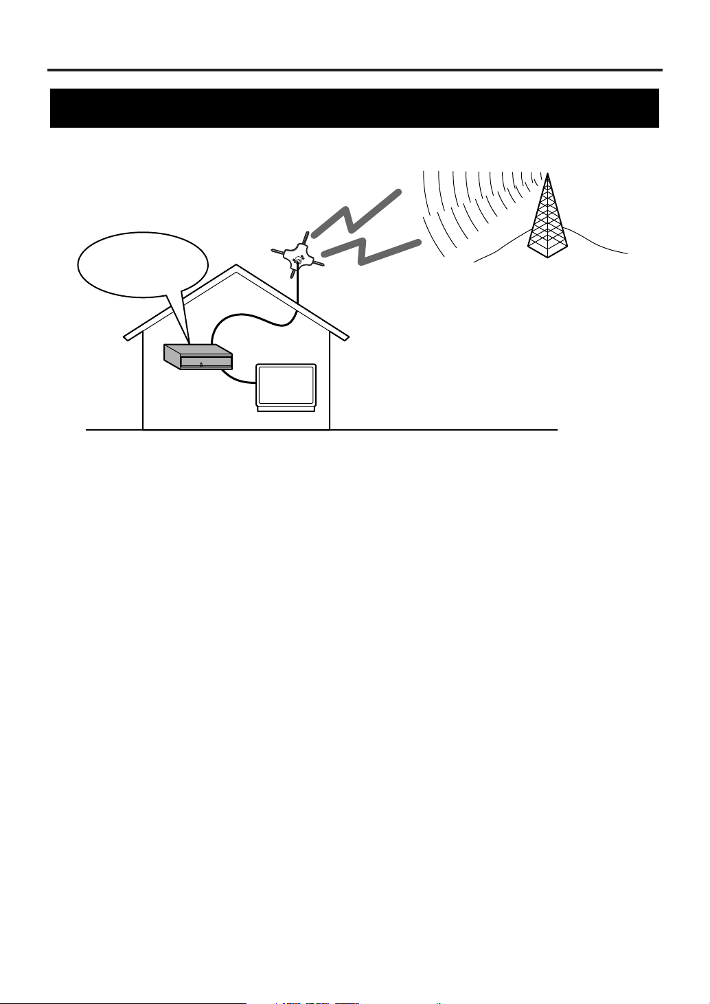
Smart Antenna*
(Digital terrestrial antenna)
Digital
terrestrial signals
ATSC
STB
(Set Top Box)
Receives ATSC
TV
Information on digital broadcasting
Digital broadcasting is the most advanced format of broadcasting, employing a new technology for
compression of audio and video signals which allows broadcasters to transmit digital signals using existing
terrestrial systems.
Due to this dramatic progress, new features of broadcasting service such as widescreen formats and higher
definition provide ways to experience the full benefits of digital transmission.
High Definition Television (HDTV*) broadcasts can provide pictures twice as sharp as a conventional
broadcast and features sound encoded with Dolby Digital* 5.1 surround sound. Connection to a receiver (sold
separately) with Dolby Digital decoding provides a true theater experience in the home.
Digital broadcasting overcomes problems experienced with analog television such as ghosting, "snowy"
pictures and interference. Digital television has a dramatic effect on these problems by its very nature.
In addition, the number of channels available has dramatically increased, so that you can make the best choice
among the variety of programs anytime with a clear picture.
The benefits extend not only to HDTV. It is also possible to transmit multiple Standard Definition Television
(SDTV*) programs within the same bandwidth. Some data capacity can also be allocated to provide more
effective closed captioning or multiple language soundtracks.
Your current TV should be used for its entire service life.
STB (Set Top Box) will make this possible.
6
EN
1A23
Page 7

Before Using
Major features of STB
• Capable of receiving digital (ATSC*) broadcasts
• Capable of receiving High Definition TV (HDTV*) or Standard Definition TV (SDTV*) broadcasts
• Capable of receiving Dolby Digital* 5.1 audio
• Digital audio output through optical or coaxial jack
• Alternative languages for OSD (English, Spanish and French)
• DVI-D* HDCP* output jack
• Component video output jacks (Y/ Pb/ Pr)
• Sub-channels* through a single digital channel
• Smart Antenna* control
ATSC - Advanced Television Systems Committee:
This group is working to establish the standards for
digital television broadcasting and digital television
equipment for both SDTV and HDTV.
HDTV - High Definition Television:
HDTV signal formats are 1080i (interlaced scan) and
720p (progressive scan). HDTV provides the highest
resolution picture and audio in either stereo or 5.1
channel surround sound.
SDTV - Standard Definition Television:
SDTV signal formats are 480p and 480i. SDTV
provides lower resolution, yet presents a very sharp,
clear picture. Lower resolution allows broadcasters to
transmit multiple programs per channel.
Dolby Digital:
Dolby Digital can provide 6 independent soundtrack
channels through the DIGITAL AUDIO OUT (OPT.
or COAX.) jack. Connect to an external Digital
Audio receiver/decoder to enjoy more dynamic and
realistic sound at home.
DVI - Digital Visual Interface:
This interface transmits the video signal digitally, so
there is less deterioration, which results in a higher
quality picture. When connected to a HDCPcompliant television you can also watch copyprotected movies and television programs.
HDCP - High-bandwidth Digital Content Protection:
Digital broadcasting allows you to view highresolution movies and television programs in your
own home. HDCP technology prevents these highquality images from copyright infringement.
Sub-Channel:
The compression of audio and video signals enables
each digital channel to carry different programs on
sub-channels. Select them by simply pressing CH o /
p buttons on your remote control when available.
Smart Antenna:
The Smart Antenna conforms to the CEA-909
standard. The STB controls the Smart Antenna,
automatically tuning to strong signals, so you do not
have to worry about the antenna once you have
completed initial installation and setup.
1 Before
Using
EN
1A23
7
Page 8
Before Using
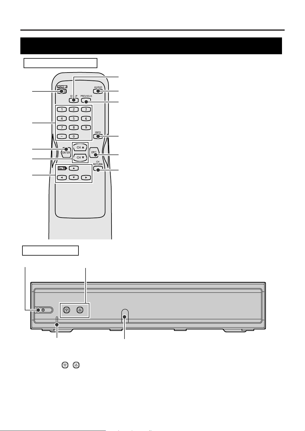
Location of controls
REMOTE CONTROL
1
2
3
4
5
6
7
8
9
10
11
1POWER button: Turns STB on and off.
2 Number buttons: Input channel numbers, passwords
and to set time.
3 ENTER button: In SETUP menu, press to enter your
selection.
4CH oo/ ppbuttons: Change the channels up or down.
5Navigation buttons oo/ pp/ ss/ BB: Moves the
highlight up, down, left or right.
Press STILL
listen to the audio.
6 SETUP button: Enters or quits SETUP menu.
7AUDIO button: Selects alternative audio languages (if
available).
8 PREVIOUS button: Returns to the previous screen in
SETUP menu or exits from the menu.
9 INFO button: Displays information on the channel
banner or clears the banner.
10 EPG button: Displays or exits the Electronic Program
Guide.
11 CH RETURN button: Returns to the channel you
were last watching.
oo
to still the video while you continue to
FRONT PANEL
12
POWER CHANNEL
43
1POWER button: Turns STB on and off.
2 CHANNEL buttons: Change the chan-
nels up or down.
3Remote control sensor: Receives signals from
your remote control so you can control the STB from a
distance.
8
EN
1A23
/
4POWER indicator : Lights up while STB is on.
When you turn the STB on, it blinks first and then
lights up.
When you turn the STB off, it blinks first and then
goes off.
Page 9
Before Using
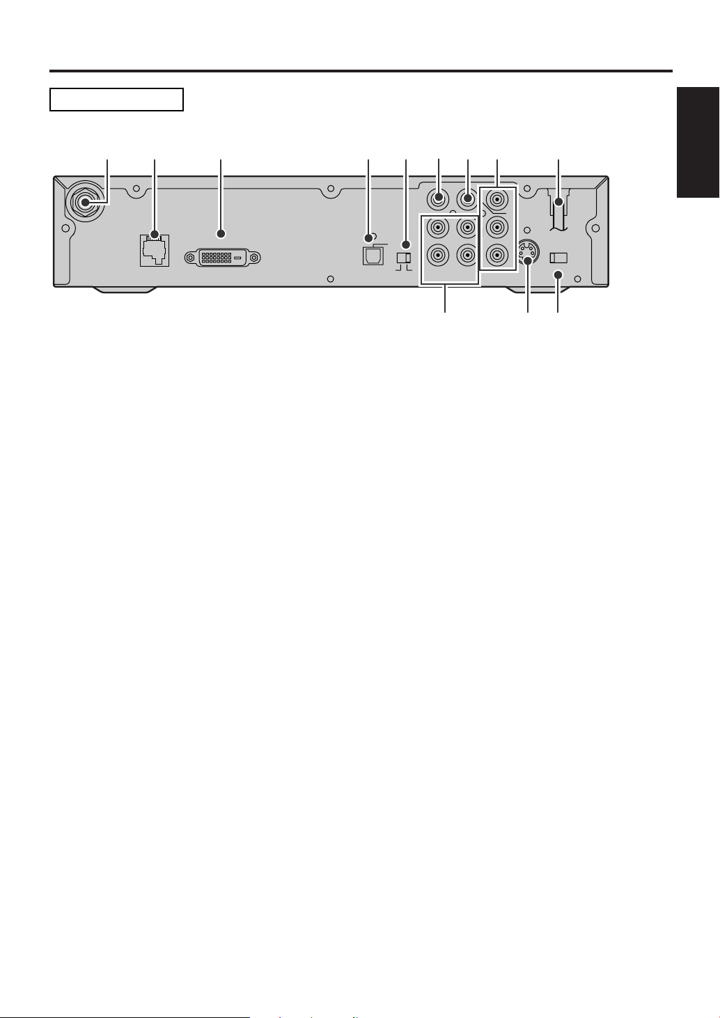
REAR PANEL
15
ANT.IN
263 4 7 8 9
D. AUDIO OUT
ANT.
CTL
DVI-D HDCP OUT
D.AUDIO
OUT
OPT
DVI COMP.
CVBS
OUT
L
L
R
12
AUDIO OUT
COMP.
OUT
Y
COAX.
Pb
Pr
S-VIDEO
RESOLUTION
SELECT
1080i/720p/480p
OUT
101112
1 ANT. IN jack: Connect an antenna.
2 ANT. CTL jack: Connect the control cord of the smart antenna. Not for phone jack.
3DVI-D HDCP OUT jack: Use this connection or the COMP.OUT jacks to enjoy HDTV. Connect a television
that conforms to EIA-861 and HDCP. Some HD Monitors designed for PC applications using the DVI-D jack may
not work with this connection.
4 DIGITAL AUDIO OUT (OPT.) jack: Connect a decoder or an amplifier with a digital optical cable. Use this
jack or the coaxial jack to connect to a receiver with Dolby Digital for Dolby Digital 5.1 playback.
5DVI, COMP. switch: When you have connected to the DVI-D HDCP OUT jack, switch this to DVI. For the
COMP. OUT jacks connections, switch to COMP..
1 Before
Using
6 CVBS OUT jack (Composite): Connect your TV or VCR with a standard video cable.
7 DIGITAL AUDIO OUT (COAX.) jack: Connect a decoder or an amplifier with a digital coaxial cable. Use
this jack or the optical jack to connect to a receiver with Dolby Digital for Dolby Digital 5.1 playback.
8 COMP. OUT jacks (Y/ Pb/ Pr): Use this connection or the DVI-D HDCP OUT jack to enjoy HDTV. Connect
your TV with component video cables.
Y (green), Pb (blue), Pr (red)
9AC power cord: Connect to AC outlet.
10 RESOLUTION SELECT switch (1080i/ 720p/ 480p): Select the STB video output resolution - 1080i,
720p or 480p. The default setting is 1080i. Change this setting to suit your television when you have connected
through either the DVI-D HDCP OUT jack or the COMP. OUT jacks.
11 S-VIDEO OUT jack: Connect your TV with an S-Video cable.
12 AUDIO OUT jacks (2 pairs): Connect your TV, stereo system or VCR to with standard audio cables.
NOTE for audio output: Both digital and analog audio are output during digital broadcasts. When you want
digital audio output, connect a digital decoder to the digital audio (coaxial or optical) jack. Refer to the page
describing connection to a decoder with Dolby Digita
l.
EN
1A23
9
Page 10
Before Using
R
NE144UD
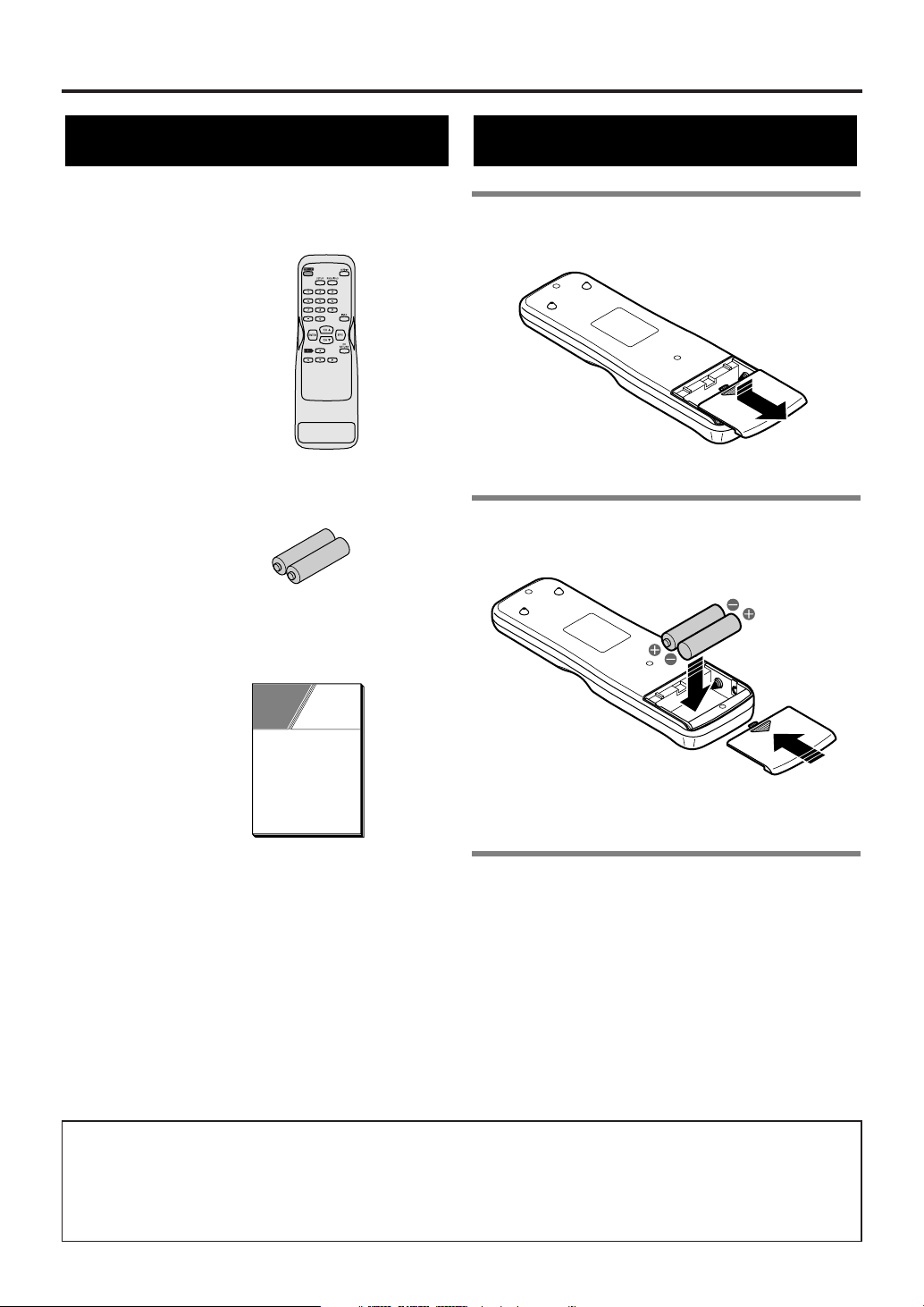
Accessories
Check the following accessories when unpacking the STB:
emote control:
2 AA batteries
Owner’s manual: 0EMN02517
Installing batteries
1 Unsnap the battery cover from the back
of the remote control.
2Install two AA batteries making sure
the polarity (+ / -) is correct.
OWNER’S
MANUAL
NOTE:
When replacing batteries, replace them in pairs.
3 Snap the battery cover back.
CAUTION:
• Do not mix battery types (alkaline and manganese).
• Do not recharge, short-circuit, heat, burn or
disassemble batteries.
A NOTE ABOUT RECYCLING
This product’s packaging materials are recyclable and can be reused. Please dispose of any materials in
accordance with your local recycling regulations.
Batteries should never be thrown away or incinerated but disposed of in accordance with your local regulations concerning chemical wastes.
10
EN
1A23
Page 11
Antenna Connections
D. AUDIO OUT
COAX.
L
Pb
Pr
L
R
12
Y
CVBS
OUT
COMP.
OUT
ANT.
CTL
D.AUDIO
OUT
DVI COMP.
DVI-D HDCP OUT
OPT
S-VIDEO
OUT
RESOLUTION
SELECT
1080i/720p/480p
ANT.IN
AUDIO OUT
Rear panel of STB
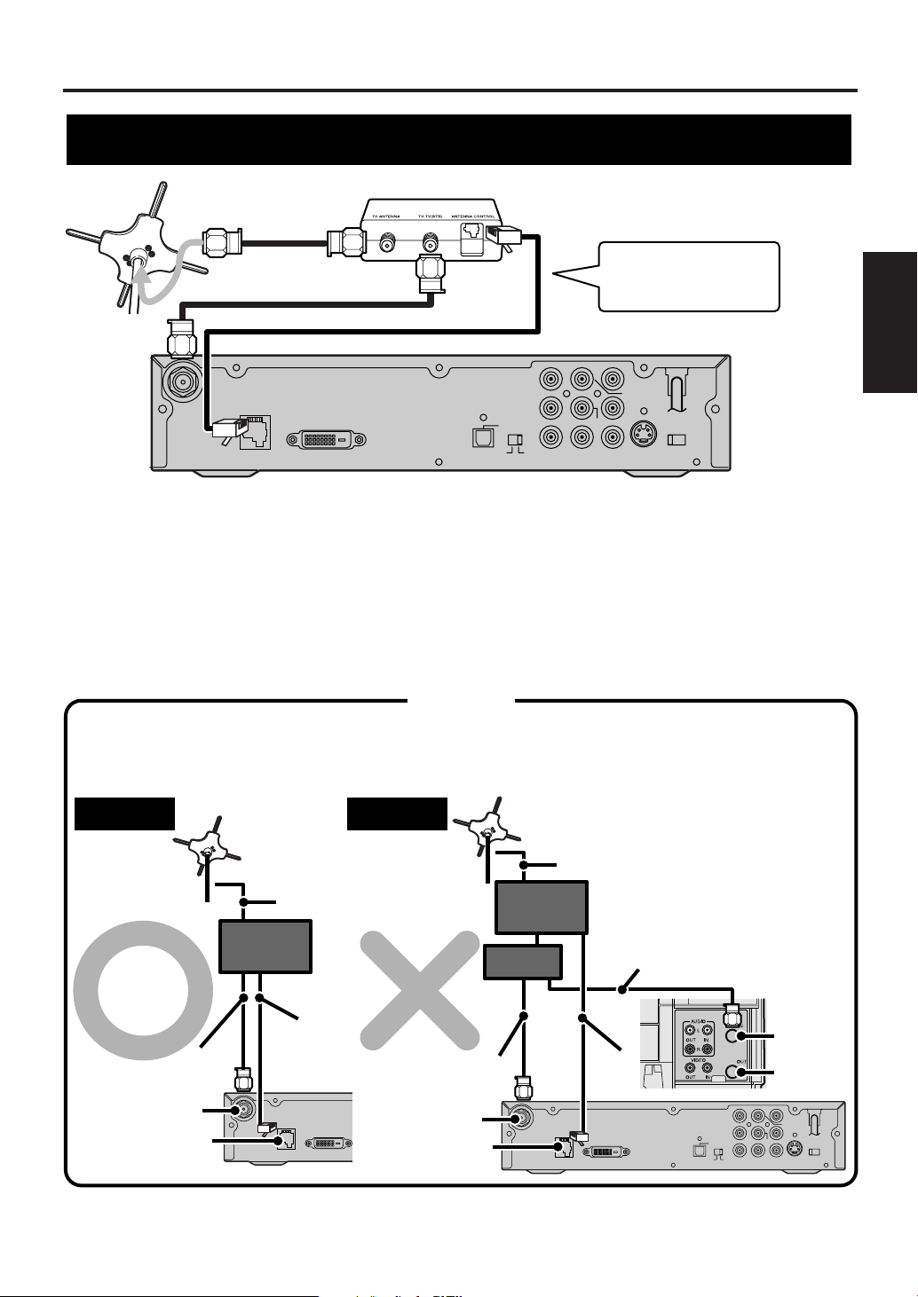
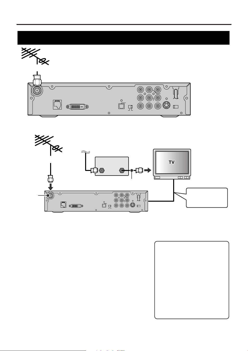
NOTE:
Antenna cable is not included.
Control box
Smart Antenna
Refer to your Smart
Antenna’s manual
for details.
CAUTION
The charactoristics of the Smart Antenna mean it is only suitable for connection to one STB.
Connect one STB to one Smart Antenna.
Do not connect other equipment between the control box, the Smart Antenna and STB.
NOTE:
Antenna and Antenna cable
are not included.
Right
ANT. IN
ANT. CTL
Antenna
cable
Smart Antenna
Antenna
cable
Antenna
control
cable
STB
Control
box
D. AUDIO OUT
COAX.
L
Pb
Pr
L
R
12
Y
CVBS
OUT
COMP.
OUT
ANT.
CTL
D.AUDIO
OUT
DVI COMP.
DVI-D HDCP OUT
OPT
S-VIDEO
OUT
RESOLUTION
SELECT
1080i/720p/480p
ANT.IN
AUDIO OUT
ANT. CTL
Wrong
e.g.: Connection to VCR
ANT. IN
RF-IN
RF-OUT
Antenna cable
Smart Antenna
Antenna
cable
Antenna
cable
STB
Control
box
Splitter
Antenna
control
cable
Connecting the Smart Antenna
Before connecting, ensure the AC power cord is NOT connected to the AC outlet.
To connect the Smart Antenna, refer to your Smart Antenna’s manual for details.
1 Use a 75 ohm coaxial antenna cable to connect the Smart Antenna to the TO ANTENNA jack on the
control box.
2 Use another 75 ohm coaxial antenna cable to connect the TO TV (STB) jack on the control box to the
ANT. IN jack on the STB.
3 Use the Smart Antenna control cable to connect the ANTENNA CONTROL jack on the control box to the
ANT. CTL jack on the STB.
4 Refer to pages 14-21 to connect to your audiovisual equipment.
Connections
2 Antenna
ANT.IN
NOTE:
If unit is not connected properly according to diagram unit may experience power failure.
DVI-D HDCP OUT
ANT.
CTL
11
EN
1A23
Page 12
Antenna Connections
D. AUDIO OUT
COAX.
L
Pb
Pr
L
R
12
Y
CVBS
OUT
COMP.
OUT
ANT.
CTL
D.AUDIO
OUT
DVI COMP.
DVI-D HDCP OUT
OPT
S-VIDEO
OUT
RESOLUTION
SELECT
1080i/720p/480p
ANT.IN
AUDIO OUT
D. AUDIO OUT
COAX.
L
Pb
Pr
L
R
12
Y
CVBS
OUT
COMP.
OUT
ANT.
CTL
D.AUDIO
OUT
DVI COMP.
DVI-D HDCP OUT
OPT
S-VIDEO
OUT
RESOLUTION
SELECT
1080i/720p/480p
ANT.IN
AUDIO OUT
Rear panel of STB
To the antenna
To the antenna
WHEN CONNECTING TO CABLE BOX ALSO:
NOTE:
Antenna and Antenna cable are not included.
ANT. IN
Incoming cable
signals
NOTE:
Antenna, Antenna cable and Cable box are not included.
STB
CABLE BOX
TV
ANT-IN
Jack
Refer to following
pages for the
connection to TV.
ANT
IN
ANT
OUT
Antenna cable
Connecting a different antenna
Before connecting, ensure the AC power cord is NOT connected
to the AC outlet.
1 Connect the Smart Antenna (or a different one if you wish).
Signal is best when using Smart Antenna.
2 Connect the incoming cable to the antenna input jack on the
cable box.
3 Connect the antenna output jack on the cable box to the
antenna input jack on the TV.
4 Plug the AC power cord of the TV into the AC outlet, then turn
the TV on.
5 Select the output channel from the cable box e.g., ch3 or ch 4.
NOTE:
Refer to your television’s manual for details.
6 Plug the AC power cord of STB into the AC outlet, then turn
STB on.
7 Refer to pages 14-21 to connect to your audiovisual
equipment.
12
EN
1A23
Note to the Cable TV System
Installer :
This reminder is provided to call
the Cable TV system installer’s
attention to Article 820-40 of the
National Electrical Code, which
provides guidelines for proper
grounding - in particular,
specifying that the cable ground
shall be connected to the grounding
system of the building, as close to
the point of cable entry as possible.
Page 13
Antenna Connections
D. AUDIO OUT
COAX.
L
Pb
Pr
L
R
12
Y
CVBS
OUT
COMP.
OUT
ANT.
CTL
D.AUDIO
OUT
DVI COMP.
DVI-D HDCP OUT
OPT
S-VIDEO
OUT
RESOLUTION
SELECT
1080i/720p/480p
ANT.IN
AUDIO OUT
D. AUDIO OUT
COAX.
L
Pb
Pr
L
R
12
Y
CVBS
OUT
COMP.
OUT
ANT.
CTL
D.AUDIO
OUT
DVI COMP.
DVI-D HDCP OUT
OPT
S-VIDEO
OUT
RESOLUTION
SELECT
1080i/720p/480p
ANT.IN
AUDIO OUT
e.g.: Connection to VCR
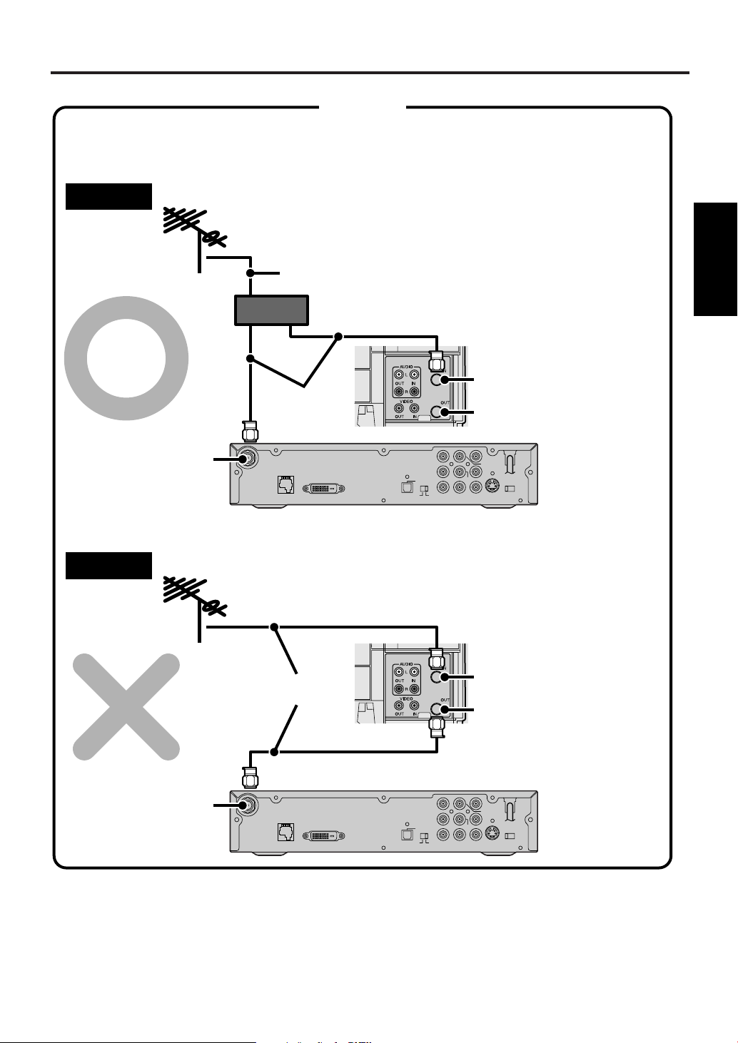
When you connect the antenna cable to another device, be sure to use a splitter as shown below.
CAUTION
Right
Splitter
ANT. IN
ANT. IN
RF-IN
RF-OUT
e.g.: Connection to VCR
STB
Wrong
RF-IN
RF-OUT
Antenna cable
Antenna
cables
Antenna
cables
NOTE:
Antenna and Antenna cable are not included.
STB
Connections
2 Antenna
13
EN
1A23
Page 14
TV/Monitor Connections
D. AUDIO OUT
COAX.
L
Pb
Pr
L
R
12
Y
CVBS
OUT
COMP.
OUT
ANT.
CTL
D.AUDIO
OUT
DVI COMP.
DVI-D HDCP OUT
OPT
S-VIDEO
OUT
RESOLUTION
SELECT
1080i/720p/480p
ANT.IN
AUDIO OUT
Rear panel of STB
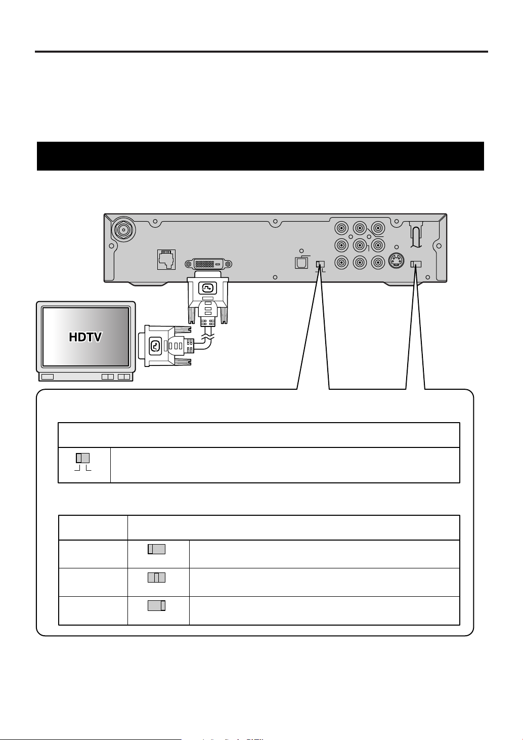
DVI video cable
To the DVI input jack
NOTE:
DVI video cable is not included.
RESOLUTION SELECT switch (1080i/720p/480p)
See your television’s manual for details on the resolutions it can handle.
Position of RESOLUTION SELECT switch
Select 1080i if your television can show 1080i resolution video.
Select 720p if your television can show 720p resolution video.
Select 480p if your television can show 480p resolution video.
1080i
720p
480p
TV resolution
Output selection switch (DVI, COMP.)
See your television’s manual for details on the types of jacks it has.
Position of output selection switch
Switch to DVI. The STB outputs video through the DVI-D HDCP OUT jack,
at the resolution you select with the RESOLUTION SELECT switch.
e.g.: Connection to HDTV
1080i/720p/480p
1080i/720p/480p
1080i/720p/480p
DVI COMP.
There are various ways of connecting the STB to a TV or monitor. Connect according to your equipment and
screen format. The following pages show some sample connections.
• Choose one type of video connection (unless you also want to connect a recording device).
• When changing connections, turn all devices off.
• Refer to each owner’s manual for further information on other devices.
• After connecting the TV or monitor, choose the type of audio connection you want.
STB connection using DVI-D HDCP OUT jack to HDTV
14
EN
1A23
Page 15

TV/Monitor Connections
1 Refer to "Antenna Connections" to connect the STB to the Smart Antenna (or a different one if you wish).
2 Use a DVI (DVI-D) video cable to connect the DVI-D HDCP OUT jack on the STB to the DVI input jack
on your television.
NOTE:
Connect to a DVI input jack that conforms to EIA-861 and HDCP. Some HD Monitors designed for PC applications
using the DVI-D jack may not work with this connection. Refer to your television’s manual for details.
3 Switch the Output selection switch (DVI, COMP.) to "DVI".
4 Switch the RESOLUTION SELECT switch (1080i/720p/480p) to suit your television.
Refer to your television’s manual for details.
5 Plug the AC power cord of the television into the AC outlet and turn the television on.
6 Switch the input mode of the television to that corresponding to the DVI input jack.
Refer to your television’s manual for details.
7 Plug the AC power cord of the STB into the AC outlet and turn it on.
Connection to a TV or monitor
Connections
3 TV/Monitor
15
EN
1A23
Page 16
TV/Monitor Connections
D. AUDIO OUT
COAX.
L
Pb
Pr
L
R
12
Y
CVBS
OUT
COMP.
OUT
ANT.
CTL
D.AUDIO
OUT
DVI COMP.
DVI-D HDCP OUT
OPT
S-VIDEO
OUT
RESOLUTION
SELECT
1080i/720p/480p
ANT.IN
AUDIO OUT
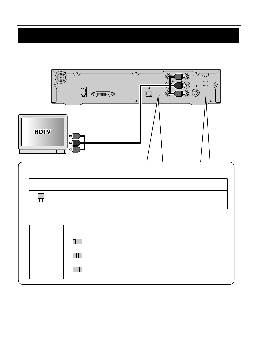
RESOLUTION SELECT switch (1080i/720p/480p)
See your television’s manual for details on the resolutions it can handle.
Position of RESOLUTION SELECT switch
Select 1080i if your television can show 1080i resolution video.
Select 720p if your television can show 720p resolution video.
Select 480p if your television can show 480p resolution video.
1080i
720p
480p
TV resolution
Output selection switch (DVI, COMP.)
See your television’s manual for details on the types of jacks it has.
Position of output selection switch
Switch to COMP. The STB outputs video through the COMP. OUT (Y, Pb, Pr)
jacks, at the resolution you select with the RESOLUTION SELECT switch.
e.g.: Connection to HDTV
Rear panel of STB
Component
video cable
To component video
input jacks (Y/ Pb/ Pr)
NOTE:
Component video cable is not included.
1080i/720p/480p
1080i/720p/480p
1080i/720p/480p
DVI COMP.
STB connection using COMP. OUT jacks to HDTV
16
EN
1A23
Page 17

TV/Monitor Connections
1 Refer to "Antenna Connections" to connect the STB to the Smart Antenna (or a different one if you wish).
2 Use Component video cables to connect the COMP. OUT (Y/ Pb/ Pr) jacks on the STB to the component
video input jacks on your television.
3 Switch the Output selection switch (DVI, COMP.) to "COMP.".
4 Switch the RESOLUTION SELECT switch (1080i/720p/480p) to suit your television.
Refer to your television’s manual for details.
5 Plug the AC power cord of the television into the AC outlet and turn the television on.
6 Switch the input mode of the television to that corresponding to the component video input jacks.
Refer to your television’s manual for details.
7 Plug the AC power cord of the STB into the AC outlet and turn it on.
Connections
3 TV/Monitor
17
EN
1A23
Page 18
TV/Monitor Connections
D. AUDIO OUT
COAX.
L
Pb
Pr
L
R
12
Y
CVBS
OUT
COMP.
OUT
ANT.
CTL
D.AUDIO
OUT
DVI COMP.
DVI-D HDCP OUT
OPT
S-VIDEO
OUT
RESOLUTION
SELECT
1080i/720p/480p
ANT.IN
AUDIO OUT
Rear panel of STB
To S-video input jack
S-video cable
Or
NOTE:
S-video cable and Video cable are not included.
Video cable
To video input jack
e.g.: Connection to SDTV
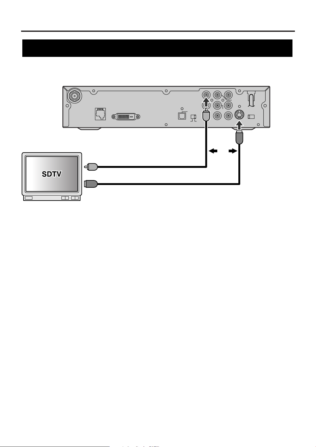
STB connection using S-VIDEO OUT or CVBS OUT (Composite) jack to SDTV
1 Refer to "Antenna Connections" to connect the STB to the Smart Antenna (or a different one if you wish).
2 Use an S-video cable to connect the S-VIDEO OUT jack on STB to an S-video input jack on the TV.
OR
Use a standard video cable to connect the CVBS OUT jack (Composite) on STB to a video input jack on your
TV.
3 Plug the AC power cord of the television into the AC outlet and turn the television on.
4 Switch the input mode of the television to that corresponding to the jack you connected to.
Refer to your television’s manual for details.
5 Plug the AC power cord of the STB into the AC outlet and turn it on.
NOTE:
When using either of these connections, the resolution of the video signal output will always be 480i.
18
EN
1A23
Page 19
Other Connections
D. AUDIO OUT
COAX.
L
Pb
Pr
L
R
12
Y
CVBS
OUT
COMP.
OUT
ANT.
CTL
D.AUDIO
OUT
DVI COMP.
DVI-D HDCP OUT
OPT
S-VIDEO
OUT
RESOLUTION
SELECT
1080i/720p/480p
ANT.IN
AUDIO OUT
Digital Decoder
Coaxial digital
audio cable
Optical digital
audio cable
To Coaxial digital
audio input jack
To Optical digital
audio input jack
Rear panel of STB
NOTE:
Optical and Coaxial digital audio cables are not included.
Or
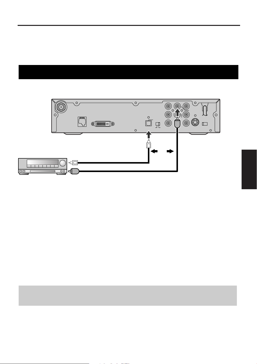
e.g.: Connection to Digital Decoder
There are various ways of connecting the STB to an audio device or video device. Connect according to your
equipment. The following pages show some sample connections.
• Choose one type of audio connection (unless you also want to connect a recording device).
• When changing connections, turn all devices off.
• Refer to each owner’s manual for further information on other devices.
STB connection to a decoder with Dolby Digital
Connections
4 Other
1 Refer to "Antenna Connections" to connect the STB to the Smart Antenna (or a different one if you wish).
2 Refer to “TV/Monitor Connections” to connect STB and the TV with a video cable.
3 Connect an Optical or Coaxial digital audio cable from the DIGITAL AUDIO OUT (OPT. or COAX.) jack
on STB to an Optical or Coaxial digital audio input jack on the digital decoder.
4 Plug the AC power cord of the decoder into an AC outlet, then turn the decoder on.
5 Set the decoder to the input mode.
Refer to your decoder’s manual for details.
6 Plug the AC power cord of STB into an AC outlet and turn it on.
Dolby information:
Manufactured under license from Dolby Laboratories. "Dolby" and the double-D symbol are trademarks
of Dolby Laboratories.
19
EN
1A23
Page 20
Other Connections
D. AUDIO OUT
COAX.
L
Pb
Pr
L
R
12
Y
CVBS
OUT
COMP.
OUT
ANT.
CTL
D.AUDIO
OUT
DVI COMP.
DVI-D HDCP OUT
OPT
S-VIDEO
OUT
RESOLUTION
SELECT
1080i/720p/480p
ANT.IN
AUDIO OUT
STEREO COMPONENT
Rear panel of STB
Audio cable
To audio input jacks
(L, R)
NOTE:
Audio cable is not included.
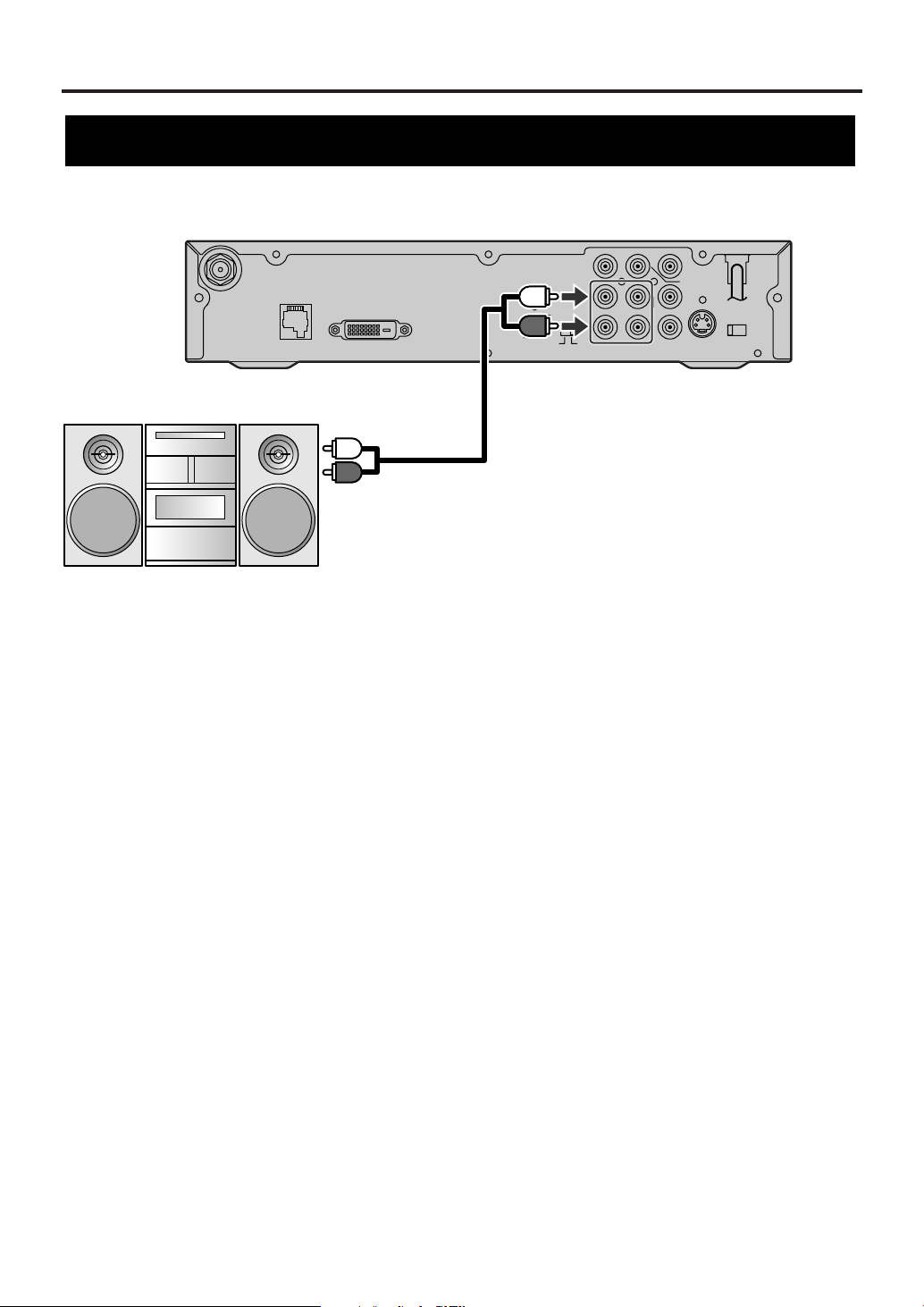
e.g.: Connection to STEREO COMPONENT
STB connection to a standard stereo system
1 Refer to "Antenna Connections" to connect the STB to the Smart Antenna (or a different one if you wish).
2 Refer to “TV/Monitor Connections” to connect STB and the TV with a video cable.
3 Use a standard audio cable to connect the AUDIO OUT jacks (L, R) on the STB to the audio input jacks
(L, R) on the stereo.
4 Plug the AC power cord of the stereo into the AC outlet, then turn the stereo on.
5 Set the stereo to the input mode to which you connected the audio from the STB.
Refer to your stereo’s manual for details.
6 Plug the AC power cord of STB into the AC outlet and turn it on.
20
EN
1A23
Page 21
Other Connections
D. AUDIO OUT
COAX.
L
Pb
Pr
L
R
12
Y
CVBS
OUT
COMP.
OUT
ANT.
CTL
D.AUDIO
OUT
DVI COMP.
DVI-D HDCP OUT
OPT
S-VIDEO
OUT
RESOLUTION
SELECT
1080i/720p/480p
ANT.IN
AUDIO OUT
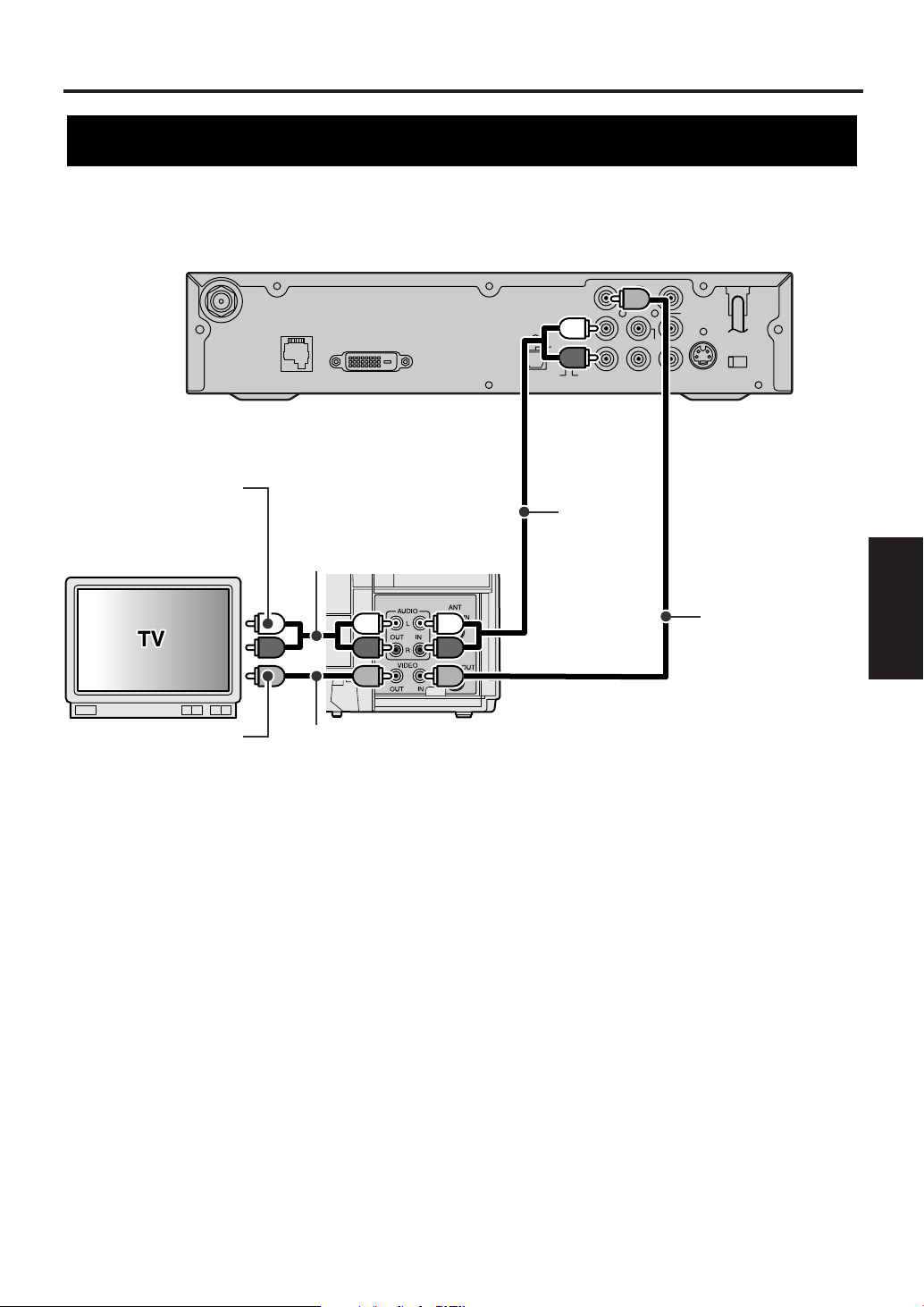
e.g.: Connection to VCR
Rear panel of STB
VCR
Video cable
Video
cable
Audio
cable
To video input
jack
To audio input
jacks (L, R)
NOTE:
Audio and Video cables are not included.
Audio cable
STB connection to TV and Video devices (VCR, DVD recorder, etc)
Connections
4 Other
1 Refer to "Antenna Connections" to connect the STB to the Smart Antenna (or a different one if you wish).
2 Use a standard audio cable to connect the AUDIO OUT jacks (L, R) on the STB to the audio input jacks (L,
R) on the VCR.
NOTE:
If your VCR is monaural (MONO) and has only one audio jack, use a standard audio cable (white) to connect the
AUDIO OUT jack (white) on STB to the audio input jack (white) on the VCR. The red cable and jack will not be
used.
3 Use a standard video cable to connect the CVBS OUT jack (Composite) on the STB to the video input
jack on the VCR.
4 Use a standard video cable to connect the video output jack on the VCR to the video input jack on the TV.
5 Use a standard audio cable to connect the set of audio output jacks (L, R) on the VCR to the audio input
jacks (L, R) on the TV.
6 Plug all AC power cords into AC outlets, then turn all devices on.
7 Set the TV and VCR to input mode.
Refer to your television’s or VCR’s manual for details.
NOTE:
When using this connection, the resolution of the video signal output will always be 480i.
21
EN
1A23
Page 22
Initial Setups (Setup Wizard)
Initial setup
SETUP WIZARD
The SETUP WIZARD is a convenient way for you to
customize the settings of STB.
When STB is turned on for the first time after
connecting the AC power cord, SETUP WIZARD is
displayed on the screen automatically. You can
complete the following items for the Initial Setups
through this menu.
• Language for screen
• Channel Scanning
• Daylight savings time (DST)
• Time zone
• Year/ date/ time
• Clock
• Screen ratio and display mode
POWER
Number buttons
ENTER
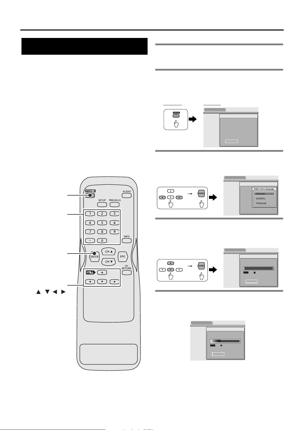
1Turn the TV on and select the input to
which the STB is connected to.
2Turn the STB on using POWER. SETUP
WIZARD appears.
• It takes about 8 seconds to display the SETUP
WIZARD after turning the power ON.
Remote: Screen:
SETUP WIZARD
SETUP WIZARD guides you
through initial setup.
:
"Create new setup"
"SETUP"
:
"Keep old setup"
"QUIT"
QUIT SETUP
3 Select SETUP using navigation buttons
ss/ BB
, then press ENTER.
• SETUP WIZARD 1/8 appears.
SETUP WIZARD 1/8
4 Select the language using navigation
oo/ pp
buttons
• The selected language is activated.
• SETUP WIZARD 2/8 appears.
, then press ENTER.
SETUP WIZARD 2/8
Now the system is scanning for channels.
22
EN
1A23
Navigation
buttons
/ / /
0%
Channel Found
SKIP
5 STB starts scanning channels.
• Wait until scanning is completed.
• When scanning is completed, “100%” is indicated in
the box, then the next screen appears.
SETUP WIZARD 2/8
Now the system is scanning for channels.
34%
Channel Found
SKIP
To skip scanning:
Press ENTER.
NOTE:
• STB receives available digital channels and stores
them in a channel map. These channels can then be
selected using CH oo/ ppbuttons after Initial Setup.
• If you skip step [5], digital channels may not be
received correctly.
Page 23

SETUP WIZARD 6/8
Select a channel for auto clock setting.
4
26
Searching.
5
4
3
2
OFF
Time info on 4CH.
Searching.
SET
CANCEL
SETUP WIZARD 6/8
Select a channel for auto clock setting.
4
Channel search
completed.
5
4
3
2
OFF
SETUP WIZARD 6/8
Select a channel for auto clock setting.
4 7
Searching.
5
4
3
2
OFF
SETUP WIZARD 5/8
Enter current time.
2004YEAR
1
DATE
31
10 30 PM
TIME
SET
Sat
or
SETUP WIZARD 5/8
Enter current time.
2001YEAR
--
DATE
-- ---
-- -- --
TIME
SET
SETUP WIZARD 4/8
Select your time zone.
CENTRAL
SETUP WIZARD 3/8
Do you observe daylight saving time
(DST)?
OFF
ON
Initial Setups (Setup Wizard)
• To get many more digital channels from your Smart
Antenna, do the EXTENDED SCAN when you
have completed the SETUP WIZARD.
See “Receiving channels” on page 39 for details.
6 SETUP WIZARD 3/8 appears.
7 Select ON or OFF for Daylight Saving
Time (DST) using navigation buttons
BB
, then press ENTER.
• SETUP WIZARD 4/8 appears.
ss
8 Select your time zone using navigation
buttons
oo/ pp/ ss/ BB
• SETUP WIZARD 5/8 appears.
, then press ENTER.
NOTE:
After all information is entered, the cursor moves to
SET.
TIP:
To enter the YEAR, enter the last 2 digits of the year.
(e.g., enter “04” and 2004 will be shown.)
10 Press ENTER when the cursor is on
SET.
• Your settings are activated.
• SETUP WIZARD 6/8 appears, then STB starts
searching for channels with Automatic Clock
Adjustment to keep the time correct.
/
• Channels with clock data are listed and turn black in
the channel map.
• “Channel search completed.” appears when the search
is completed.
• “No channels found.” appears if the STB could not find
any channels with clock data.
5 Initial Setups
(Setup Wizard)
NOTE :
See “INFORMATION on Time Zones ” on pages 44-45.
9 Enter YEAR, DATE and TIME using
navigation buttons
oo/ pp/ ss/ BB
number buttons.
• Every time you enter a number, press ENTER to move
the cursor.
• When going back and forth, press navigation buttons
/B to move the cursor.
or
11 Use the navigation buttons
oo/ pp
select the channel you want to gather
clock data from in the channel map,
then press ENTER.
• If you do not want to use AUTO to set the time, select
OFF and press ENTER.
• Five channels appear in the map at a time. Keep
oo/ pp
pressing the navigation buttons
channels.
• The time info window appears and the STB starts
s
searching for the time info on channel you selected.
to show other
to
23
EN
1A23
Page 24

26-1
World News 25
WWOR
ENGLISH
SETUP WIZARD 8/8
Select display mode.
SIDEBAR
ZOOM
FULL
SETUP WIZARD 7/8
Select screen ratio.
16:9
4:3
SETUP WIZARD 6/8
Select a channel for auto clock setting.
4
26
Searching.
5
4
3
2
OFF
Time info on 4CH.
Thu, Dec 13, 2001
10:30 PM
SET
CANCEL
Initial Setups (Setup Wizard)
• When the STB has finished gathering the time
information, the current date and time according to the
channel appears.
• “No time info.”appears if the STB could not find time
information from the channel you selected.
12 If this information shown is
satisfactory, use the navigation buttons
oo/ pp
to select SET and press ENTER.
• SETUP WIZARD 7/8 appears.
• If the time shown is incorrect or the time isn’t shown,
select CANCEL, press ENTER. Then, repeat steps [11]
and [12] using another channel.
NOTE:
Unit should not be left on for a long period of time, it
may cause over heating.
13 Select the screen ratio using navigation
buttons
• SETUP WIZARD 8/8 appears.
See “Selecting screen formats” on page 41 for
details.
oo/ pp
, then press ENTER.
14 Select the desired display mode using
navigation buttons
o / p,then press
ENTER.
• SETUP WIZARD is completed.
STB starts receiving broadcasts.
See “Selecting screen formats” on page 41 for details.
24
EN
1A23
Page 25

Basic Operation
26-1
Puffy the Vampire Slayer
WWOR
TV-Y
2:00PM- 3:00PM
Doublement Palace: Puffy takes a new job at a fast food restaurant
to make ends meet. Sarah Michelle Gellar, Nicholas Brendon, Alyson
Hannigan, Elizabeth Anne Allen, Kari Rocha.
ENGLISH
26-1
Main channel
Sub-channel
POWER
Number buttons
CH RETURN
ENTER
CH /
Watching TV
STB can receive digital (ATSC format) broadcasts.
Tune to the available digital channels with the CH
o/p buttons and number buttons on the remote
control.
Each channel number consists of a main channel
number and a sub-channel number.
1Turn the TV on and select the input to
which the STB is connected to.
2Turn the STB on using POWER.
• The power indicator on the front panel blinks then
lights up.
Remote:
3 Selecting channels.
When using CH oo/ppbuttons:
• Press CH o button to tune a higher channel number.
• Press CH p button to tune a lower channel number.
Complete AUTOSCAN (limited digital channels) in
SETUP WIZARD or EXTENDED SCAN in the
SETUP menu so that STB receives all available
digital channels.
When using number buttons (E.g., entering
26-1):
1. Enter the main channel number, press the “–” button,
then enter the sub-channel number.
NOTE:
Every channel number consists of a main channel
and a sub-channel.
Screen:
TIP:
Press the “–” button before entering the subchannel number.
25
EN
1A23
Operation
6 Basic
Page 26

: changes automatically
: change manually by pressing CH
/
button
on your remote control.
CH4-1
18:00
18:30
19:00
19:30
20:00
CH4-2
CH4-1
CH4-1
CH4-1 CH4-2
CH4-3
ATSC
Basic Operation
2. Press ENTER.
• STB tunes in channel 26-1 and the program being
broadcast appears.
To select only with a main channel number
(E.g., 55 ):
• X appears momentarily as an alternate sub-
channel, then STB receives the sub-channel with
the smallest sub-channel number.
An alternate Sub-channel
55-X
SCANNING
About sub-channel broadcasting:
There may be different programs being broadcast on
sub-channels through a single channel.
You can watch each sub-channel program by
selecting one of the sub-channels.
NOTE:
NO SIGNAL appears after the sub-channel broadcast
is over.
Change the channel to continue watching.
The School
OTHER
55-1
To return to the channel you were last
watching:
• The STB returns to the channel you were last watching.
26
EN
1A23
Page 27

Basic Operation
Channel banner
The channel banner provides you with information
on the channel you have selected.
INFO
1 Press INFO to display the channel
banner.
• Channel information appears in the channel banner.
Screen:
Remote:
Puffy the Vampire Slayer
TV-Y
2:00PM- 3:00PM
Doublement Palace: Puffy takes a new job at a fast food restaurant
to make ends meet. Sarah Michelle Gellar, Nicholas Brendon, Alyson
Hannigan, Elizabeth Anne Allen, Kari Rocha.
WWOR
ENGLISH
26-1
2 Press INFO to clear.
27
EN
1A23
Operation
6 Basic
Page 28

Basic Operation
Information icons
DTV:
Indicates that you are tuning in a digital channel.
HD (High Definition):
Indicates that the program being broadcast has a high definition signal with screen ratio
16:9.
SD (Standard Definition):
Indicates that the program being broadcast has standard definition signal with screen ratio
16:9.
SD (Standard Definition):
Indicates that the program being broadcast has standard definition signal with screen ratio
4:3.
LOCK:
Indicates that the current program is blocked according to your V-CHIP setting.
CC (Closed Caption):
Indicates that the program being broadcast is available with closed captioning.
V-CHIP/CC:
Indicates that V-CHIP/CC has been set to TV.
Refer to "Setting for V-CHIP/CC" on page 49 for further information.
Program title
Program rating
Program description
Channel number :
Indicates the current channel number.
Logo for broadcast source
Audio language
Location bar :
Indicates the start and end times,
and the current status of progress.
26-1
Puffy the Vampire Slayer
WWOR
TV-Y
2:00PM- 3:00PM
Doublement Palace: Puffy takes a new job at a fast food restaurant
to make ends meet. Sarah Michelle Gellar, Nicholas Brendon, Alyson
Hannigan, Elizabeth Anne Allen, Kari Rocha.
ENGLISH
Information icons
(See below for detail.)
Components of Channel Banner
28
EN
1A23
Page 29

Basic Operation
77-1
No description provided.
ENGLISH 1/3
CAT0001
ENGLISH 1/3
OTHER 3/3
SPANISH 2/3
First Language
Third Language
Second Language
Choosing audio and language
You can change languages through an audio-map
when the channel provides alternate languages.
Audio map:
Languages from a station are stored in an audio-map.
For example, when three languages are available, the
sequence below repeats and the desired language can
be set.
AUDIO
1 Press AUDIO.
Remote:
The sequence repeats according to the audio-map.
Screen:
NOTE:
OTHER is indicated when the language is not
English, Spanish or French.
* For international stations audio language will still
be displayed as English.
29
EN
1A23
Operation
6 Basic
Page 30

Basic Operation
Picture Still
You can stop the picture on the screen anytime by
pressing STILL
STILL
o button.
1 Press STILL oobutton while watching
TV.
• STILL is indicated on the lower left while the picture is
displayed.
Screen:
Remote:
STILL
The program’s audio continues.
2 Press any button to quit.
• The picture currently being broadcast appears.
NOTE:
If the TV is left on STILL for a long period of
time, the still image may cause a burn-in effect
damaging the TV screen.
30
EN
1A23
Page 31

On screen messages
Some messages are displayed on the screen during
channel changing or during programs.
NO SIGNAL
When STB cannot receive a channel signal, the
whole screen becomes gray, then NO SIGNAL
appears in the center.
This may occur when:
• the signal is too weak
(when using the Smart Antenna, it automatically
searches for the strongest signal.)
• the channel is not broadcasting
• the antenna cable is not connected
SCANNING
Basic Operation
This program is protected and cannot be viewed on TV without
HDCP-compliant DVI.
To watch this program, select “COMP.” by DVI/COMP. Select Switch and use
video output other than DVI.
The STB receives digital broadcasts with embedded
“broadcast flag” and enciphers them with the HDCP
system and outputs them from the DVI-D HDCP
jack.
Your television must also be HDCP-compliant to
view them via DVI jack. This message appears if
your television is not compliant with HDCP.
You can still view the program, by using another type
of video connection. See “TV/Monitor Connections”
for the alternatives and switch the output selection
switch (DVI/COMP.) on back of STB to COMP.
“Broadcast flags” are digital codes embedded in
digital broadcasting streams that signal the STB to
limit indiscriminate redistribution of content.
When STB is trying to receive a signal, the whole
screen becomes gray, then SCANNING appears in
the center.
RESTRICTED PROGRAM
When you have set V-CHIP and you receive a
program that meets any setting of yours, the whole
screen becomes gray, then RESTRICTED
PROGRAM appears in the center.
See “Setting MPAA rating” on page 51 or “Setting TV
rating” on page 53 for further information.
Press INFO to verify the rating of a program
currently being received.
Screen:
Remote:
No description provided.
TV-14 D
No description provided.
The rating of this program
Cowboy
RESTRICTED PROGRAM
ENGLISH
51-1
Operation
6 Basic
31
EN
1A23
Page 32

Advanced Operation
Electronic Program Guide (EPG)
Electronic Program Guide (EPG) is an application for
digital channels that lists current and scheduled
programs that are or will be available on each
channel and a short summary or commentary for
each program.
EPG is the electronic equivalent of a printed
television program guide.
You can view a list of programs scheduled for the
next few hours up to the next seven days.
NOTE:
For displaying EPG, you will need to set TIME
ZONE, DST and MANUAL CLOCK in SETUP
WIZARD or in SETUP menu.
PREVIOUS
ENTER
EPG
1 Press EPG button while watching TV.
• EPG appears on the screen.
Remote:
Screen:
EPG
)
TODAY (Sat
26- 1
WWOR
WPIX
26- 2
26- 3
WCBSDT
27- 1
WCBR
71- 1
NWOC
NSDT
84- 1
26-2
CURRENT TIME:
Sat, Jan 31 2:55 PM
2:00PM 3:00PM
Buffy the Vampire Sl...
Gilmore Girls
JAG
Ster Trek:Voyager Spin City... The 5th ...
Frasier
Late Show Wi...
Gilmore Girls
2:00PM-3:00PM
Richard in Stars Hollow: Lorelao's retired father visits
and drivers her and Rory crazy critizing all aspests of
their lives. Lauren Graham, Alexis Bledel, Edward
State of the Union
Smallville
Cheers Taxi Suddenl...
The Late Show W... Rend...
See “Components of Electronic Program Guide
(EPG)” on page 33 for details.
2 Select the desired program using
navigation buttons
• The cursor moves as you press any navigation button.
To view EPG for the next two hours up to the
next seven days:
Press navigation button B.
• EPG for the next two hours appears.
• Keep pressing navigation button B to move the EPG
ahead.
oo/ pp/ ss/ BB
EPG
2:00PM 3:00PM
)
TODAY (Sat
26- 1
WWOR
Buffy the Vampire Sl...
WPIX
26- 2
Gilmore Girls
26- 3
WCBSDT
JAG
27- 1
WCBR
Ster Trek:Voyager Spin City... The 5th ...
71- 1
NWOC
Frasier
NSDT
84- 1
Late Show Wi...
26-3
JAG
2:00PM-3:00PM
.
CURRENT TIME:
Sat, Jan 31 2:55 PM
State of the Union
Smallville
Cheers Taxi Suddenl...
The Late Show W... Rend...
Navigation
buttons
/ / /
32
EN
1A23
To go back to the previous page:
Press navigation button s.
• EPG for the previous page appears.
• Keep pressing navigation button s to move the EPG
ahead.
3Press ENTER.
When you select a program being broadcast:
• The selected program appears.
JAG
WCBSDT
ENGLISH
26-3
Page 33

To clear the EPG:
Press EPG or PREVIOUS.
The previous program appears.
Screen:
Remote:
or
Components of Electronic Program Guide (EPG)
Day of broadcasting
Channel numbers and digital
broadcasting station
Program viewing :
Shows the program being
broadcast on the channel you are
choosing.
TODAY (Sat
Gilmore Girls
26- 1
26- 2
26- 3
27- 1
71- 1
84- 1
WPIX
EPG
)
WWOR
WPIX
WCBSDT
WCBR
NWOC
26-2
Advanced Operation
26-2
ENGLISH
Current bar :
Indicates the current time
(so you can see how close you are to the start or end time of the program).
CURRENT TIME:
Sat, Jan 31 2:07 PM
2:00PM 3:00PM
Buffy the Vampire Slay...
Gilmore Girls
JAG
Ster Trek:Voyager Spin City... The 5th ...
Frasier
Cheers Taxi Suddenly...
State of the Union
Smallville
Gilmore Girls
2:00PM-3:00PM TV-Y
Richard in Stars Hollow: Lorelao's retired father visits
and drives her and Rory crazy criticizing all aspests of
their lives. Lauren Graham, Alexis Bledel, Edward
Current time
Program list
Cursor :
Highlights the program currently
selected.
Program information :
Indicates the Information of the
program currently highlighted.
NOTE:
For channel numbers with blank description, the broadcasting
station may not provide signals for EPG.
Information icons
LOCK:
Indicates that the current program is blocked according to your V-CHIP setting.
CC (Closed Caption):
Indicates that the program being broadcast is available with closed captioning.
33
EN
1A23
7 Advanced
Operation
Page 34

Advanced Operation
Setup menu options
includes:
• ADD / DELETE:
Add or delete channels in the channel map.
• ANTENNA:
Verify and adjust the signal strength of each channel to get a clearer picture.
• AUTOSCAN:
Get available digital channels automatically into the channel map by completing AUTOSCAN or EXTENDED SCAN.
includes:
• SCREEN RATIO:
Fit the screen ratio to your TV screen.
• DISPLAY MODE:
Choose the display mode you prefer.
includes:
• Daylight Saving Time (DST):
Set the Daylight Savings Time (DST).
• TIME ZONE:
Set the time zone.
• MANUAL:
Set the clock manually.
• AUTO:
Adjust the clock automatically using the channel clock data included in the signal from digital broadcast sources.
includes:
• V-CHIP/ CC:
Make some settings for V-CHIP and closed caption including your own password.
• MENU LANGUAGE:
Choose English, French or Spanish for the screen menu.
• SOUND EFFECTS:
Choose whether to have sounds on or off when using on screen menus.
34
EN
1A23
Page 35

ADD/DELETE
QUIT
CHANNEL
DISPLAY
CLOCK
DETAIL
13-1
ADD
DELETE
55
23
22
13
CHANNEL
QUIT
CHANNEL
DISPLAY
CLOCK
DETAIL
ADD/DELETE
ANTENNA
AUTOSCAN
SETUP
QUIT
CHANNEL
DISPLAY
CLOCK
DETAIL
Advanced Operation
Adding/Deleting channels
Add or delete desired channels in the channel map.
NOTE :
Once you add (or delete) channels in a channel map,
you can select (or skip) the channels in order using
CH o / p buttons.
SETUP
Number
buttons
ENTER
Navigation
buttons /
1 Press SETUP to display SETUP menu.
Screen:
Remote:
2 Select CHANNEL using navigation
buttons
• CHANNEL menu appears.
oo/ pp
, then press ENTER.
3 Select ADD/ DELETE using navigation
buttons
• ADD/ DELETE menu appears.
oo/ pp
, then press ENTER.
35
EN
1A23
7 Advanced
Operation
Page 36

Advanced Operation
Adding channels
E.g., deleting channel 26.
4 Enter channel number 26.
ADD/DELETE
QUIT
ADD
DELETE
CHANNEL
DISPLAY
CLOCK
DETAIL
5 Select ADD using navigation buttons
pp
/
, then press ENTER.
• 26 is added to the channel map.
ADD/DELETE
QUIT
ADD
DELETE
CHANNEL
DISPLAY
CLOCK
DETAIL
NOTE:
Channels can be added only with main channel
numbers. When the channel has sub-channels,
however, you can select the sub-channels with CH o
/ p buttons.
To continue adding:
Repeat steps [4] and [5].
Added
26-1
13
22
23
55
26-1
13
22
23
26
oo
6 Press SETUP to exit SETUP menu.
Deleting channels
E.g., deleting channel 26.
4 Select DELETE using navigation
buttons
• The cursor moves to the channel map.
oo/ pp
, then press ENTER.
ADD/DELETE
CHANNEL
DISPLAY
CLOCK
DETAIL
QUIT
ADD
DELETE
13-1
13
22
25
26
5 Select the digital channel number 26
oo/ pp
using navigation buttons
.
• 26-1 is indicated in the box at the top of the screen.
ADD
DELETE
Indicated
26-1
13
22
23
26
ADD/DELETE
QUIT
CHANNEL
DISPLAY
CLOCK
DETAIL
TIP:
To add a channel number you deleted, add it by
following the steps in the ADD menu or renew the
whole channel map with the AUTOSCAN menu.
6 Press ENTER when the cursor is on the
digital channel 26.
• The digital channel number 26 will be deleted.
ADD/DELETE
QUIT
CHANNEL
DISPLAY
CLOCK
DETAIL
ADD
DELETE
55-1
13
22
23
55
36
EN
1A23
To continue deleting:
Repeat steps [5] and [6].
NOTE:
: Indicates that there are more channels above
/
or below.
7 Press SETUP to exit SETUP menu.
Page 37

ADD/DELETE
QUIT
CHANNEL
DISPLAY
CLOCK
DETAIL
26-1
ADD
DELETE
26
23
22
13
Channel map
: Indicates a digital channel.
Information on channel map
Advanced Operation
37
EN
1A23
7 Advanced
Operation
Page 38

ANTENNA
QUIT
CHANNEL
DISPLAY
CLOCK
DETAIL
26-1
WEAK STRONG
PREVIOUS
NOW
56
PEAK
75
CHANNEL
QUIT
CHANNEL
DISPLAY
CLOCK
DETAIL
ADD/DELETE
ANTENNA
AUTOSCAN
SETUP
QUIT
CHANNEL
DISPLAY
CLOCK
DETAIL
26-1
Carrie and the News Today
WWOR
ENGLISH
Advanced Operation
Adjusting antenna
ANTENNA
You can verify the signal strength of each channel to
get a clearer picture.
SETUP
E.g., to adjust channel 26-1.
1 Select channel 26-1 to adjust using
number buttons or CH
Remote:
oo/ pp
buttons.
or
Screen:
Number
buttons
ENTER
CH /
Navigation
buttons /
2 Press SETUP to display SETUP menu.
3 Select CHANNEL using navigation
buttons
• CHANNEL menu appears.
oo/ pp
, then press ENTER.
4 Select ANTENNA using navigation
buttons
• ANTENNA menu appears, then STB starts receiving
the signal strength of the channel.
oo/ pp
, then press ENTER.
38
EN
1A23
Page 39

ANTENNA
QUIT
CHANNEL
DISPLAY
CLOCK
DETAIL
26-1
WEAK STRONG
PREVIOUS
NOW
75
PEAK
75
Current value
Peak value
Advanced Operation
5 Adjust the Smart Antenna’s height (or
direction if you are using an ordinary
antenna) to get the best reception.
• A status bar stretches to the right according to the
signal strength.
• The value will be indicated on the left of the status bar
so that you can adjust the antenna.
NOTE :
Once you have correctly installed the Smart
Antenna, you do not have to adjust its height or
position again.
To adjust other channels:
Select the channel with CH o / p buttons, then adjust it.
To cancel during adjustment:
Press SETUP or ENTER.
Receiving channels
AUTOSCAN
STB can get available digital channels automatically.
AUTOSCAN receives available digital channels and
stores them in a channel map. These channels can
then be selected using CH o / p buttons.
CAUTION:
If AUTOSCAN is skipped, digital channels may not
be received correctly.
NOTE:
To get many more digital channels from your Smart
Antenna, do the EXTENDED SCAN. This enables
you to receive many more digital channels than
AUTOSCAN. It takes about 20 minutes.
SETUP
6 Press SETUP to exit SETUP menu.
ENTER
CH /
Navigation
buttons /
39
EN
1A23
7 Advanced
Operation
Page 40

2-1
NO SIGNAL
7-1
State of the union
MONAURAL
AUTOSCAN COMPLETED
AUTOSCAN
QUIT
Now the system is scanning for channels.
100%
Channel Found
2-1
AUTOSCAN CANCELLED
or
AUTOSCAN
QUIT
Now the system is scanning for channels.
Autoscan Extended scan
Takes about 3 minutes. Takes about 20 minutes.
11%
Channel Found
EXTENDED SCAN
QUIT
Now the system is scanning for channels.
Remaining Time:
11%
18
min
Channel Found
AUTOSCAN
QUIT
CHANNEL
DISPLAY
CLOCK
DETAIL
(approx 20min)
AUTOSCAN
EXTENDED SCAN
CHANNEL
QUIT
CHANNEL
DISPLAY
CLOCK
DETAIL
ADD/DELETE
ANTENNA
AUTOSCAN
SETUP
QUIT
CHANNEL
DISPLAY
CLOCK
DETAIL
Advanced Operation
1 Press SETUP to display SETUP menu.
Screen:
Remote:
2 Select CHANNEL using navigation
oo/ pp
buttons
, then press ENTER.
• CHANNEL menu appears.
3 Select AUTOSCAN using navigation
oo/ pp
buttons
• AUTOSCAN menu appears.
, then press ENTER.
To cancel during scanning:
Press SETUP or ENTER.
• AUTOSCAN CANCELLED appears on the screen.
NOTE:
If cancelled, some channels not yet scanned may not
be received. We recommend completing
AUTOSCAN or EXTENDED SCAN.
5 Scan is completed.
• SETUP menu goes off automatically and STB starts
receiving broadcasts.
4 Select AUTOSCAN or EXTENDED
SCAN using navigation buttons
then press ENTER.
• The Scanning screen appears while the STB scans for
available digital channels and adds them to the channel
map.
TIP:
When you want to completely reflesh the channel
map, use ADD/DELETE to delete all the channels,
then do the AUTOSCAN again.
See “Deleting channels” on page 36 for details.
40
EN
1A23
oo/ pp
,
Press CH o / p buttons to verify whether STB is
receiving channels being broadcast.
When NO SIGNAL appears on the screen:
Verify the antenna connection, then scan again.
The STB tunes in channel 2-1 and NO SIGNAL
appears if the STB could not receive any channels.
Page 41

DISPLAY
QUIT
CHANNEL
DISPLAY
CLOCK
DETAIL
SCREEN RATIO
4:3
DISPLAY MODE
LETTERBOX
DISPLAY
QUIT
CHANNEL
DISPLAY
CLOCK
DETAIL
SCREEN
DISPLAY
Select screen ratio.
16:9
4:3
DISPLAY
QUIT
CHANNEL
DISPLAY
CLOCK
DETAIL
SCREEN RATIO
16:9
DISPLAY MODE
SIDEBAR
SETUP
QUIT
CHANNEL
DISPLAY
CLOCK
DETAIL
Advanced Operation
Selecting screen formats
(Screen ratio and Display mode)
STB allows you to select a screen ratio and a display
mode (aspect ratio) to match the formats of the
program being broadcast on your TV screen.
You can also change to aspect ratios you prefer to
watch.
SCREEN RATIO
There are two screen ratios used in manufacturing
TVs. These are standard TV format (4:3) and
widescreen format (16:9).
Aspect ratio is the ratio of the screen width to height.
SETUP
1 Press SETUP to display SETUP menu.
Screen:
Remote:
2 Select DISPLAY using navigation
oo/ pp
buttons
, then press ENTER.
• DISPLAY menu appears.
3 Select SCREEN RATIO using navigation
oo/ pp
buttons
• Screen ratio options appear.
, then press ENTER.
Navigation
buttons /
ENTER
4 Select the desired screen ratio using
oo/ pp
navigation buttons
, then press
ENTER.
• The screen ratio is set.
5 Press SETUP to exit SETUP menu.
NOTE:
Select the screen ratio to fit your TV screen.
See your television’s manual for details.
41
EN
1A23
7 Advanced
Operation
Page 42

Advanced Operation
DISPLAY MODE
1 Press SETUP to display SETUP menu.
Screen:
Remote:
SETUP
QUIT
CHANNEL
DISPLAY
CLOCK
DETAIL
2 Select DISPLAY using navigation
buttons
• DISPLAY menu appears.
oo/ pp
, then press ENTER.
CHANNEL
DISPLAY
DISPLAY
QUIT
CLOCK
DETAIL
SCREEN RATIO
DISPLAY MODE
16:9
SIDEBAR
3 Select DISPLAY MODE using navigation
buttons
• Display mode options appear.
oo/ pp
, then press ENTER.
CHANNEL
DISPLAY
DISPLAY
QUIT
CLOCK
DETAIL
SCREEN
Select display mode.
DISPLAY
SIDEBAR
ZOOM
FULL
4 Select the desired display mode using
oo/ pp
navigation buttons
, then press
ENTER.
• The display mode is set.
DISPLAY
QUIT
CHANNEL
DISPLAY
CLOCK
DETAIL
SCREEN RATIO
DISPLAY MODE
16:9
SIDEBAR
NOTE:
Choose the display mode as you prefer.
See “INFORMATION on Screen Ratio and Display
Mode” on page 43 for further information.
5 Press SETUP to exit SETUP menu.
CAUTION:
If the TV is left in LETTERBOX or SIDEBAR for
a long period of time, the still image may cause a
burn-ing effect, damaging the TV screen.
Important information about
screen ratio and display mode
Depending on the type of TV you have, you
may encounter one of the following problems.
4:3 TV
If you have a 4:3 aspect HDTV, bars may appear
at the top and bottom of the picture when you
input 1080i signals. If you have set the STB to
SCREEN RATIO 16:9 and SIDEBAR, the
screen may appear as shown here.
appears because of TV settings.
STB
1080i video
output signal
4:3 TV
appears because of STB settings.
We recommend setting the STB’s screen ratio to
4:3 and the display mode to suit your preference.
Alternatively, set the resolution selection switch
on the rear panel to “480p”. See your TV
owner’s manual for details.
16:9 TV
A double set of sidebars may appear on the left
and right of the picture, squeezing it into the
center of the screen. This can occur if you have
set the resolution selection switch on the rear
panel to “480p”, because the television may
recognize the signal as 4:3, regardless of the
screen ratio setting you have made on the STB.
appears because of TV settings.
16:9 TV
480p video
STB
output signal
appears because of STB settings.
If your television can handle 1080i or 720p
signals, set the resolution selection switch on the
rear panel to the resolution for your television. If
it cannot handle either of these, then change the
display mode on your television.
42
EN
1A23
Page 43

Advanced Operation
Letter Box
Displays the entire picture image while fitting the picture
to the screen by applying gray
bars to
the top and bottom of the screen.
No information will be lost.
Zoom
Expands the picture image to fill the screen while cropping some images on the left and right.
Picture information on the left and right side will be lost.
Full
Displays the entire picture image while fitting the picture to the screen by stretching the
image
vertically, so that it fills the screen.
No information will be lost, but there may be a slight distortion of the picture.
Sidebar
Displays the entire picture centering the image b
y applying gray
bars to the left and right sides of
the screen.
No information will be lost.
Zoom
Expands the picture image to fill the screen while cropping some images on the top and bottom.
Picture information on the top and bottom will be lost.
Full
Displays the entire picture image while fitting the picture to the screen by stretching the
image
horizontally, so that it fills the screen.
No information will be lost, but there may be a slight distortion of the picture.
For standard 4:3 TVs displaying widescreen 16:9 broadcasts, your choices are:
For widescreen 16:9 TVs displaying standard 4:3 broadcasts, your choices are:
4:3 TV screen 16:9 broadcast
16:9 TV screen 4:3 broadcast
INFORMATION on Screen Ratio and Display Mode
7 Advanced
Operation
43
EN
1A23
Page 44

CLOCK
QUIT
CHANNEL
DISPLAY
CLOCK
DETAIL
DST
ON
TIME ZONE
CENTRAL
MANUAL
AUTO
OFF
Sat, Jan 31, 2004 2 50PM
CLOCK
QUIT
CHANNEL
DISPLAY
CLOCK
DETAIL
ON
Do you observe daylight saving time
(DST)?
OFF
CLOCK
QUIT
CHANNEL
DISPLAY
CLOCK
DETAIL
DST
ON
TIME ZONE
CENTRAL
MANUAL
AUTO
OFF
Sat, Jan 31, 2004 2 50PM
SETUP
QUIT
CHANNEL
DISPLAY
CLOCK
DETAIL
Advanced Operation
Setting the clock
To get the EPG (Electronic Program Guide) and
Channel banner, you will need to set the CLOCK
correctly.
NOTE:
The clock function is necessary to display the EPG
so there may be 10 seconds-time lag a day at the
maximum. Therefore we recommend setting
AUTO to ON.
Set Daylight Saving Time (DST) and TIME ZONE
before setting the clock. These will be influential
when setting the current time.
SETUP
Number buttons
1 Press SETUP to display SETUP menu.
Screen:
Remote:
2 Select CLOCK using navigation buttons
oo/ pp
, then press ENTER.
• CLOCK menu appears.
3 Select DST using navigation buttons
pp
, then press ENTER.
• Daylight saving time setting menu appears.
oo
/
44
EN
1A23
Navigation
buttons
/ / /
ENTER
4 Select ON or OFF using navigation
buttons
• Daylight savings time is set, then CLOCK menu
appears.
ss/ BB
, then press ENTER.
Page 45

5 Select TIME ZONE using navigation
CLOCK
QUIT
CHANNEL
DISPLAY
CLOCK
DETAIL
DST
ON
TIME ZONE
CENTRAL
MANUAL
AUTO
OFF
Wed, Mar 31, 2004 1 52PM
Activated
CLOCK
QUIT
CHANNEL
DISPLAY
CLOCK
DETAIL
Enter current time.
TIME 52 PM1
DATE 313 Wed
YEAR 2004
SET
or
CLOCK
QUIT
CHANNEL
DISPLAY
CLOCK
DETAIL
Enter current time.
TIME 50 PM
DATE 3121 Sat
YEAR 2004
SET
CLOCK
QUIT
CHANNEL
DISPLAY
CLOCK
DETAIL
DST
ON
TIME ZONE
CENTRAL
MANUAL
AUTO
OFF
Sat, Jan 31, 2004 2 50PM
ALASKA
ALASKA:
HAWAII
HAWAII:
PACIFIC
PACIFIC:
CENTRAL
CENTRAL:
EASTERN
EASTERN:
ATLANTIC
ATLANTIC:
MOUNTAIN
MOUNTAIN:
Time Zones
CLOCK
QUIT
CHANNEL
DISPLAY
CLOCK
DETAIL
Select your time zone.
CENTRAL
buttons
• TIME ZONE setting menu appears.
oo/ pp
, then press ENTER.
Advanced Operation
• To go back and forth, press navigation buttons s / B.
After you enter all information, the cursor moves to SET.
TIP:
To enter the YEAR, enter the last 2 digits (e.g., enter
“04” using number buttons; 2004 will be shown.)
9 Press ENTER when the cursor is on
SET.
• Your settings are activated.
6 Select your time zone using navigation
buttons
oo/ pp/ ss/ BB
• The TIME ZONE is set, then CLOCK menu appears.
, then press ENTER.
7 Select MANUAL using navigation
buttons oo/ pp, then press ENTER.
• The current time setting menu appears.
8 Enter YEAR, DATE and TIME using
navigation buttons
number buttons.
• Press ENTER to set each value and the cursor moves to
the next.
oo/ pp/ ss/ BB
or
10 Press SETUP to exit SETUP menu.
45
EN
1A23
7 Advanced
Operation
Page 46

CLOCK
QUIT
CHANNEL
DISPLAY
CLOCK
DETAIL
Select a channel for auto clock setting.
5
3
2
4
Channel search
completed.
4
OFF
CLOCK
QUIT
CHANNEL
DISPLAY
CLOCK
DETAIL
Select a channel for auto clock setting.
2
Searching.
5
4
3
2
OFF
CLOCK
QUIT
CHANNEL
DISPLAY
CLOCK
DETAIL
DST
ON
TIME ZONE
CENTRAL
MANUAL
AUTO
OFF
Sat, Jan 31, 2004 2 50PM
SETUP
QUIT
CHANNEL
DISPLAY
CLOCK
DETAIL
Advanced Operation
Adjusting the clock
automatically
STB can adjust the clock automatically using clock
data included in digital broadcasts.
In this menu, STB searches for channels with clock
data, then adjusts the clock using the channel you
select.
SETUP
ENTER
Navigation
buttons /
1 Press SETUP to display SETUP menu.
Screen:
Remote:
2 Select CLOCK using navigation buttons
oo/ pp
, then press ENTER.
• CLOCK menu appears.
3 Select AUTO using navigation buttons
oo/ pp
, then press ENTER.
• Auto clock setting menu appears, then STB starts
searching for channels with clock data.
46
EN
1A23
When not using the auto-clock setting:
Select OFF from the channel-map, then press ENTER.
In this case, continue with step [7].
• OFF is at the top of the channel map. Keep
pressing navigation button o to find it.
4 After scanning
• Channels with clock data are listed and turn black in
the channel map.
• “Channel search completed.” appears when the search
is completed.
• “No channels found.” appears if the STB could not find
any channels with clock data.
Page 47

SETUP
Number
buttons
ENTER
Navigation
buttons /
CLOCK
QUIT
CHANNEL
DISPLAY
CLOCK
DETAIL
DST
ON
TIME ZONE
CENTRAL
MANUAL
AUTO
4CH
Sat, Jan 31, 2004 3:00PM
CLOCK
QUIT
CHANNEL
DISPLAY
CLOCK
DETAIL
Select a channel for auto clock setting.
4
26
Searching.
5
4
3
2
OFF
Time info on 4CH.
Sat, Jan 31, 2004
3:00 PM
SET
CANCEL
CLOCK
QUIT
CHANNEL
DISPLAY
CLOCK
DETAIL
Select a channel for auto clock setting.
4
26
Searching.
5
4
3
2
OFF
Time info on 4CH.
Searching.
SET
CANCEL
Advanced Operation
5 Use the navigation buttons oo/ ppto
select the channel you want to gather
clock data from in the channel map,
then press ENTER.
• The time info window appears and the STB starts
searching for the time info on the channel you selected.
TIP:
• You can select a channel that has been found even if
the STB is still searching.
• When the STB has finished gathering the time
information, the current date and time according to the
channel appears.
• “No time info.” appears if the STB could not find time
information from the channel you selected.
V-CHIP options
Setting a new password
You will need to change the 4-digit password to
protect your V-CHIP/CC setting.
“0000” is the default password.
NOTE:
If the power supply is stopped due to a power failure
or unplugging AC power cord for approx. 5 seconds,
the password goes back to “0000.”
DO NOT forget your password.
You need it to set the V-CHIP/CC.
6 Use the navigation buttons oo/ ppto
select SET and press ENTER.
• The CLOCK menu appears.
• The selected channel is set, then the clock is activated.
• If the time shown is incorrect or the time isn’t shown,
select CANCEL, press ENTER. Then, repeat steps [5]
and [6] using another channel.
7 Press SETUP to exit SETUP menu.
7 Advanced
Operation
47
EN
1A23
Page 48

V-CHIP / CC
QUIT
CHANNEL
DISPLAY
CLOCK
DETAIL
V-CHIP / CC
STB
MPAA RATING
TV RATING
CLOSED CAPTION
NEW PASSWORD
V-CHIP / CC
QUIT
CHANNEL
DISPLAY
CLOCK
DETAIL
Enter password.
Confirm password.
V-CHIP / CC
QUIT
CHANNEL
DISPLAY
CLOCK
DETAIL
Enter password.
Confirm password.
V-CHIP / CC
QUIT
CHANNEL
DISPLAY
CLOCK
DETAIL
V-CHIP / CC
STB
MPAA RATING
TV RATING
CLOSED CAPTION
NEW PASSWORD
V-CHIP / CC
QUIT
CHANNEL
DISPLAY
CLOCK
DETAIL
Enter password.
Advanced Operation
1 Press SETUP to display SETUP menu.
Screen:
Remote:
SETUP
QUIT
CHANNEL
DISPLAY
CLOCK
DETAIL
2 Select DETAIL using navigation button
oo/ pp
, then press ENTER.
• DETAIL menu appears.
DETAIL
QUIT
V-CHIP / CC
CHANNEL
MENU LANGUAGE ENGLISH
DISPLAY
CLOCK
DETAIL
SOUND EFFECTS
OFF
3 Select V-CHIP/CC using navigation
oo/ pp
button
• V-CHIP/CC password window appears.
, then press ENTER.
V-CHIP / CC
QUIT
Enter password.
CHANNEL
DISPLAY
CLOCK
DETAIL
5 Select NEW PASSWORD using
navigation buttons
oo/ pp
, then press
ENTER.
• Password setting menu appears.
6 Enter a new 4-digit password in the
upper space, then enter again in the
lower space to confirm.
7V-CHIP/CC menu appears.
• Your new password is stored.
4 Enter the default password “0000.”
• “ ” appears for each digit.
After you enter the default password, V-CHIP/CC
menu appears.
48
EN
1A23
8 Press SETUP to exit SETUP menu.
Page 49

V-CHIP / CC
QUIT
CHANNEL
DISPLAY
CLOCK
DETAIL
V-CHIP / CC
STB
MPAA RATING
TV RATING
CLOSED CAPTION
NEW PASSWORD
V-CHIP / CC
QUIT
CHANNEL
DISPLAY
CLOCK
DETAIL
Enter password.
Advanced Operation
Setting for V-CHIP/CC
V-CHIP/CC
In this menu, you will make some important settings
for the viewing programs you select.
First, set your 4-digit password for your V-CHIP,
then proceed with the settings. Refer to “Setting a
new password” on page 47.
V- CHIP technology blocks movies and television
programs according to their ratings.
When V-CHIP and Closed Caption (CC) systems are
built into your TV, choose STB or TV as your
standard to transmit V-CHIP/CC information.
When V-CHIP/CC is set to STB, the settings you
make here are valid. Set the rating level on the STB.
When set to TV, the settings are not valid. Set the
rating level on the TV.
STB is the default.
SETUP
1 Press SETUP to display SETUP menu.
Screen:
Remote:
SETUP
QUIT
CHANNEL
DISPLAY
CLOCK
DETAIL
2 Select DETAIL using navigation buttons
oo/ pp
, then press ENTER.
• DETAIL menu appears.
DETAIL
QUIT
V-CHIP / CC
CHANNEL
MENU LANGUAGE ENGLISH
DISPLAY
CLOCK
DETAIL
SOUND EFFECTS
OFF
3 Select V-CHIP/CC using navigation
oo/ pp
buttons
• V-CHIP/CC password window appears.
, then press ENTER.
V-CHIP / CC
QUIT
Enter password.
CHANNEL
DISPLAY
CLOCK
DETAIL
Number buttons
ENTER
Navigation
buttons
/ / /
4 Enter your 4-digit password.
• “ ” appears for each digit.
After you enter the correct password, V-CHIP/CC
menu appears.
7 Advanced
Operation
49
EN
1A23
Page 50

Advanced Operation
V-CHIP / CC
QUIT
CHANNEL
DISPLAY
CLOCK
DETAIL
V-CHIP / CC
STB
MPAA RATING
TV RATING
CLOSED CAPTION
NEW PASSWORD
V-CHIP / CC
QUIT
CHANNEL
DISPLAY
CLOCK
DETAIL
STB
Choose either STB or TV for
V-CHIP/CC setting.
If you choose "TV",
V-CHIP/CC functions are processed
in TV, not in STB.
TV
5 Select V-CHIP/CC using navigation
buttons
• V-CHIP/CC setting menu appears.
6 Select STB or TV using navigation
buttons
NOTE:
To set V-CHIP/CC settings, choose STB.
oo/ pp
, then press ENTER.
ss/ BB
, then press ENTER.
If you choose “STB” to control V-CHIP Ratings:
• The STB V-CHIP/CC settings are effective.
• Make the V-CHIP/CC settings with STB.
• You can watch programs according to the
STB V-CHIP/CC settings.
If you choose “TV” to control V-CHIP Ratings:
• The STB V-CHIP/CC settings are not effective.
• You can watch programs according to the
TV V-CHIP/CC settings.
• Make the V-CHIP/CC settings with the TV. For TV
settings, refer to your television’s manual.
7 Press SETUP to exit SETUP menu.
50
EN
1A23
Page 51

Advanced Operation
Number buttons
ENTER
Navigation
buttons /
SETUP
Age Label
NR
Not Rated by MPAA
Description
G
General Audience
PG
Parental Guidance Suggested.
Some material may not be suitable for
children.
NC-17
No one 17 and under admitted.
Some material is intended to be viewed
by adults only.
X
No one 17 and under admitted.
Some material is explicitly sexual and is
intended to be viewed by adults only.
PG-13
Parents Strongly Cautioned.
Some material may be inappropriate for
children under 13.
R
Restricted.
Under 17 requires accompanying parent
or guardian.
V- CHIP is built into TVs and other video devices to work in conjunction with the TV Parental
Guidelines. It electronically reads television-programming ratings and allows parents to block programs
they believe are inappropriate for their children.
There are two rating categories in use, TV ratings (pages 53-55) for TV programs and MPAA ratings
(pages 51-52) for theatrical movies being broadcast.
Setting MPAA rating
MPAA RATING
The MPAA (Motion Picture Association of America)
uses the standard movie ratings.
51
EN
1A23
7 Advanced
Operation
Page 52

V-CHIP / CC
QUIT
CHANNEL
DISPLAY
CLOCK
DETAIL
Select MPAA rating
X
NC-17
R
PG
G
NR
PG-13
V-CHIP / CC
QUIT
CHANNEL
DISPLAY
CLOCK
DETAIL
Select MPAA rating
X
NC-17
R
PG-13
PG
G
NR
V-CHIP / CC
QUIT
CHANNEL
DISPLAY
CLOCK
DETAIL
V-CHIP / CC
STB
MPAA RATING
TV RATING
CLOSED CAPTION
NEW PASSWORD
V-CHIP / CC
QUIT
CHANNEL
DISPLAY
CLOCK
DETAIL
Enter password.
Advanced Operation
1 Press SETUP to display SETUP menu.
Screen:
Remote:
SETUP
QUIT
CHANNEL
DISPLAY
CLOCK
DETAIL
2 Select DETAIL using navigation buttons
oo/ pp
, then press ENTER.
• DETAIL menu appears.
DETAIL
QUIT
V-CHIP / CC
CHANNEL
MENU LANGUAGE ENGLISH
DISPLAY
CLOCK
DETAIL
SOUND EFFECTS
OFF
3 Select V-CHIP/CC using navigation
oo/ pp
buttons
, then press ENTER.
• V-CHIP/CC password window appears.
V-CHIP / CC
QUIT
Enter password.
CHANNEL
DISPLAY
CLOCK
DETAIL
4 Enter your 4-digit password.
• “ ” appears for each digit.
5 Select MPAA RATING using navigation
buttons
• MPAA rating setting menu appears.
oo/ pp
, then press ENTER.
6 Select your desired rating level using
oo/ pp
navigation buttons
, then press
ENTER.
E.g., to block all PG-13 movies:
• Lock indicators are added to programs rated PG-13 and
above.
NOTE:
All movie programs rated PG-13 and above are
blocked. When STB receives these programs, it
blocks video and audio output and RESTRICTED
PROGRAM appears on the screen.
After you enter the correct password, V-CHIP/CC
menu appears.
52
EN
1A23
TIP:
Press ENTER to unblock a previously blocked rating
so you can select it.
7 Press SETUP to exit SETUP menu.
Page 53

Number buttons
ENTER
Navigation
buttons
/ / /
SETUP
Age Label
TV-MA
Mature Audience Only :
Specifically designed to be viewed by
adults and therefore may be unsuitable
for children under 17.
Possible content label : L, S, V
TV-14
Parents Strongly Cautioned:
Contains some material that many
parents would find unsuitable for children
under 14 years of age.
Possible content label : D, L, S, V
TV-G
General Audience :
Most parents would find this program
appropriate for all ages.
TV-Y7
Directed to Older Children :
Designed for children age 7 and above.
Possible content label : FV
TV-Y
All Children :
Designed to be appropriate for all children.
TV-PG
Parental Guidance Suggested :
Contains material that parents may find
suitable for younger children.
Possible content label : D, L, S, V
Description
Content Label
D suggestive dialogue
Description
L coarse language
S sexual situations
V violence
FV fantasy violence
Setting TV rating
TV RATING
(TV Parental Guidelines)
TV rating allows parents to block out programs they
don’t want their children to see.
TV rating consists of age labels and content labels.
The following are the descriptions for each label:
Advanced Operation
NOTE:
When you block a particular rating or content label,
all categories above that are also blocked.
7 Advanced
Operation
53
EN
1A23
Page 54

V-CHIP / CC
QUIT
CHANNEL
DISPLAY
CLOCK
DETAIL
Set TV rating
TV-MA
TV-14
TV-PG
TV-G
TV-Y7
TV-Y
FV V S L D
Content labels
Age-based category
Possible content labels
INFORMATION on TV ratings
V-CHIP / CC
QUIT
CHANNEL
DISPLAY
CLOCK
DETAIL
Set TV rating
TV-MA
TV-14
TV-PG
TV-G
TV-Y7
TV-Y
FV V S L D
V-CHIP / CC
QUIT
CHANNEL
DISPLAY
CLOCK
DETAIL
V-CHIP / CC
STB
MPAA RATING
TV RATING
CLOSED CAPTION
NEW PASSWORD
V-CHIP / CC
QUIT
CHANNEL
DISPLAY
CLOCK
DETAIL
Enter password.
Advanced Operation
1 Press SETUP to display SETUP menu.
Screen:
Remote:
SETUP
QUIT
CHANNEL
DISPLAY
CLOCK
DETAIL
2 Select DETAIL using navigation buttons
oo/ pp
, then press ENTER.
• DETAIL menu appears.
DETAIL
QUIT
V-CHIP / CC
CHANNEL
MENU LANGUAGE ENGLISH
DISPLAY
CLOCK
DETAIL
SOUND EFFECTS
OFF
3 Select V-CHIP/CC using navigation
oo/ pp
buttons
• V-CHIP/CC password window appears.
, then press ENTER.
V-CHIP / CC
QUIT
Enter password.
CHANNEL
DISPLAY
CLOCK
DETAIL
5 Select TV RATING using navigation
buttons
• TV rating setting menu appears.
oo/ pp
, then press ENTER.
4 Enter your 4-digit password.
• “ ” appears for each digit.
After you enter the correct password, V-CHIP/CC
menu appears.
54
EN
1A23
Page 55

To set age-based ratings:
V-CHIP / CC
QUIT
CHANNEL
DISPLAY
CLOCK
DETAIL
Set TV rating
TV-MA
TV-14
TV-PG
TV-G
TV-Y7
TV-Y
FV V S L D
V-CHIP / CC
QUIT
CHANNEL
DISPLAY
CLOCK
DETAIL
Set TV rating
TV-MA
TV-14
TV-PG
TV-G
TV-Y7
TV-Y
FV V S L D
E.g., to block all TV-14 programs
1. Select TV-14 using navigation buttons o / p, then
press ENTER.
• Lock indicators are added to TV-14 and above.
Screen:
Remote:
NOTE:
All TV-14 and higher programs are blocked, along
with all the labels of their possible contents.
When STB receives these programs, it blocks video
and audio output then RESTRICTED PROGRAM
appears on the screen.
2. Press SETUP to exit SETUP menu.
Advanced Operation
To set content-based ratings:
E.g., to block only TV-14 programs that
contain higher levels of violence
1. Select TV-14-V using navigation buttons o / p / s /
B, then press ENTER.
• Lock indicators are added to TV-14-V and above.
Screen:
Remote:
NOTE:
All TV-14-V and higher programs are blocked.
When STB receives these programs, it blocks video
and audio output then RESTRICTED PROGRAM
appears on the screen.
2. Press SETUP to exit SETUP menu.
7 Advanced
Operation
55
EN
1A23
Page 56

CC1 and TEXT1:
are the primary caption and text services.
The captioning or text is displayed in the same
language as the program’s dialog.
(up to 4 lines of script on the screen, where it does
not obstruct relevant parts of the picture)
CC3 and TEXT3:
serve as the preferred data channels.
The captioning or text is often a secondary
language translation, simplified English or
displayed at a slower rate.
CC2, CC4, TEXT2 and TEXT4:
are rarely available and broadcasters use them
only in special conditions, such as when CC1 and
CC3 are not available or TEXT1 and TEXT3 are
not available.
Information on closed captions
SETUP
Number
buttons
ENTER
Navigation
buttons /
Advanced Operation
Closed caption options
CLOSED CAPTION
Closed captions are text versions of the audio content
or may provide other information while you are
watching a program. Actual content is decided by the
broadcaster.
This menu contains the following items.
CLOSED CAPTION:
OFF: Select if you do not want closed captions.
This is the default.
CC1 to CC4 and TEXT 1 to 4: Select if you want
closed captions. Select one of these before changing
any other item in the CLOSED CAPTION menu.
DTV CC:
Apart from closed captions, DTV has its own closed
captions called DTV CC. Use this menu to change
the settings for DTV CC.
OFF: Select if you do not want DTV CC. This is
the default.
SERVICE 1 to SERVICE 6: Select one of these
before changing any other item in the CLOSED
CAPTION menu. Choose SERVICE 1 under normal
circumstances.
CC STYLE:
ORIGINAL: Closed captions are displayed using
the broadcast’s original setting.
MANUAL: Closed captions are displayed using
your manual setting. Change the font, color, edge
and opacity of the closed captions.
56
EN
1A23
Page 57

CLOSED CAPTION
QUIT
CHANNEL
DISPLAY
CLOCK
DETAIL
CLOSED CAPTION
OFF
DTV CC
CC STYLE
ORIGINAL
OFF
Select service.
OFF
SERVICE1
SERVICE2
SERVICE3
SERVICE4
SERVICE5
SERVICE6
Advanced Operation
1 Press SETUP to display SETUP menu.
Screen:
Remote:
SETUP
QUIT
CHANNEL
DISPLAY
CLOCK
DETAIL
2 Select DETAIL using navigation buttons
oo/ pp
, then press ENTER.
• DETAIL menu appears.
DETAIL
QUIT
V-CHIP / CC
CHANNEL
MENU LANGUAGE ENGLISH
DISPLAY
CLOCK
DETAIL
SOUND EFFECTS
OFF
3 Select V-CHIP/CC using navigation
oo/ pp
buttons
, then press ENTER.
• V-CHIP/CC password window appears.
V-CHIP / CC
QUIT
Enter password.
CHANNEL
DISPLAY
CLOCK
DETAIL
4 Enter your 4-digit password.
• “ ” appears for each digit.
V-CHIP / CC
QUIT
Enter password.
CHANNEL
DISPLAY
CLOCK
DETAIL
After you enter the correct password, V-CHIP/CC
menu appears.
V-CHIP / CC
QUIT
CHANNEL
DISPLAY
CLOCK
DETAIL
V-CHIP / CC
MPAA RATING
TV RATING
CLOSED CAPTION
NEW PASSWORD
STB
5 Select CLOSED CAPTION using
navigation buttons
oo/ pp
, then press
ENTER.
• CLOSED CAPTION menu appears.
CLOSED CAPTION
QUIT
CHANNEL
DISPLAY
CLOCK
DETAIL
CLOSED CAPTION
DTV CC
CC STYLE
OFF
OFF
ORIGINAL
6 Select CLOSED CAPTION using
oo/ pp
navigation buttons
, then press
ENTER.
• The CLOSED CAPTION selection screen appears.
CLOSED CAPTION
QUIT
CHANNEL
DISPLAY
CLOCK
DETAIL
CLOSED CAPTION
DTV CC
CC STYLE
Select CC or text.
OFF
OFF
OFF
CC1
CC2
ORIGINAL
CC3
CC4
TEXT1
TEXT2
TEXT3
TEXT4
7 Select the setting you want for closed
captions using navigation buttons
pp
, then press ENTER.
• CLOSED CAPTION menu appears.
• Your selection is activated.
CLOSED CAPTION
QUIT
CLOSED CAPTION
DTV CC
CHANNEL
CC STYLE
DISPLAY
CLOCK
DETAIL
oo
CC1
OFF
ORIGINAL
8 Select DTV CC using navigation
oo/ pp
buttons
• The DTV CC selection screen appears.
, then press ENTER.
/
Operation
7 Advanced
57
EN
1A23
Page 58

CLOSED CAPTION
QUIT
CHANNEL
DISPLAY
CLOCK
DETAIL
Select edge.
Advanced Operation
9 Select the setting you want for DTV CC
oo/ pp
using navigation buttons
, then
press ENTER.
• CLOSED CAPTION menu appears.
• Your selection is activated.
CLOSED CAPTION
QUIT
CLOSED CAPTION
DTV CC
CHANNEL
CC STYLE
DISPLAY
CLOCK
DETAIL
NOTE:
DTV CC:
Apart from closed captions, DTV has its own closed
captions called DTV CC. Use this menu to change
the settings for DTV CC.
OFF: Select if you do not want DTV CC. This is
the default.
SERVICE 1 to SERVICE 6: Select one of these
before changing any other item in the CLOSED
CAPTION menu. Choose SERVICE 1 under normal
circumstances.
CC1
SERVICE1
ORIGINAL
11 Select the setting you want for CC
STYLE using navigation buttons
then press ENTER.
If you selected ORIGINAL
• CLOSED CAPTION menu appears.
• The CC STYLE is original.
CLOSED CAPTION
QUIT
CLOSED CAPTION
DTV CC
CHANNEL
CC STYLE
DISPLAY
CLOCK
DETAIL
Go to step [17].
If you selected MANUAL
• The Font selection screen appears.
CLOSED CAPTION
Select font.
QUIT
CHANNEL
DISPLAY
CLOCK
DETAIL
ss/ BB
CC1
SERVICE1
ORIGINAL
,
10 Select CC STYLE using navigation
oo/ pp
buttons
• The CC STYLE selection screen appears.
58
EN
1A23
, then press ENTER.
CLOSED CAPTION
QUIT
CHANNEL
DISPLAY
CLOCK
DETAIL
CC style will be displayed using
broadcast's original setting.
ORIGINAL MANUAL
12 Select the font you want using
navigation buttons
oo/ pp/ ss/ BB
, then
press ENTER.
• The Color selection screen appears.
CLOSED CAPTION
Select color.
QUIT
CHANNEL
DISPLAY
CLOCK
DETAIL
13 Select the color you want using
navigation buttons
oo/ pp/ ss/ BB
, then
press ENTER.
• The Edge selection screen appears.
NOTE:
This page is skipped if you selected a transparent
color for the foreground.
Page 59

14 Select the edge you want using
CLOSED CAPTION
QUIT
CHANNEL
DISPLAY
CLOCK
DETAIL
CLOSED CAPTION
CC1
DTV CC
CC STYLE
MANUAL
SERVICE1
navigation buttons
oo/ pp/ ss/ BB
, then
press ENTER.
• The Opacity selection screen appears.
CLOSED CAPTION
Select opacity.
QUIT
CHANNEL
DISPLAY
CLOCK
DETAIL
NOTE:
Three types are shown if you selected a transparent
color for the foreground or background.
15 Select the opacity you want using
navigation buttons
oo/ pp/ ss/ BB
, then
press ENTER.
• The CC Style preview screen appears.
CLOSED CAPTION
Preview.
QUIT
CC style you selected is shown below.
CHANNEL
DISPLAY
CLOCK
DETAIL
Closed Caption Sample
RETRY SET
Advanced Operation
16 Select SET using navigation buttons
/ BB, then press ENTER.
• CLOSED CAPTION menu appears.
• Your selection is activated.
• To do the CC STYLE settings again from Font, select
RETRY and press ENTER.
17 Press SETUP to exit SETUP menu.
ss
59
EN
1A23
7 Advanced
Operation
Page 60

SOR
TIR
CHA
NE
AFFICHAGEGE
HORLOGE
AIL
Advanced Operation
Choosing the screen language
MENU LANGUAGE
Choose English, French or Spanish for the screen
menu.
NOTE:
ENGLISH is the default.
SETUP
ENTER
Navigation
buttons /
1 Press SETUP to display SETUP menu.
Screen:
Remote:
SETUP
QUIT
CHANNEL
DISPLAY
CLOCK
DETAIL
2 Select DETAIL using navigation buttons
oo/ pp
, then press ENTER.
• DETAIL menu appears.
DETAIL
QUIT
V-CHIP / CC
CHANNEL
MENU LANGUAGE ENGLISH
DISPLAY
CLOCK
DETAIL
SOUND EFFECTS
OFF
3 Select MENU LANGUAGE using
oo/ pp
navigation buttons
, then press
ENTER.
• Language menu appears.
DETAIL
QUIT
V-CHIP / CC
MENU LANGUAGE
SOUND EFFECTS
Select menu language.
ENGLISH
OFF
ESPAÑOL
FRANÇAIS
CHANNEL
DISPLAY
CLOCK
DETAIL
4 Select the language using navigation
buttons
oo/ pp
(e.g., French), then press
ENTER.
• The language you select is now used for on-screen
displays.
DÉTAIL
SOR
TIR
SORTIR
PUCE EN V / S-T
CHA
ÎNE
CHAÎNE
LANGUE DU MENU FRANÇAIS
AFFICHA
AFFICHAGE
HORLOGE
HORLOGE
DÉTAIL
DÉTAIL
EFFETS SONORES
ARRÊT
5 Press SETUP to exit SETUP menu.
60
EN
1A23
Page 61

DETAIL
QUIT
CHANNEL
DISPLAY
CLOCK
DETAIL
V-CHIP / CC
MENU LANGUAGE ENGLISH
ON
SOUND EFFECTS
DETAIL
QUIT
CHANNEL
DISPLAY
CLOCK
DETAIL
V-CHIP / CC
MENU LANGUAGE ENGLISH
OFF
SOUND EFFECTS
SETUP
QUIT
CHANNEL
DISPLAY
CLOCK
DETAIL
SETUP
ENTER
Navigation
buttons /
Advanced Operation
Choosing sound effects
SOUND EFFECTS
Choose whether to have sounds on or off when using
on screen menus.
1 Press SETUP to display SETUP menu.
Screen:
Remote:
2 Select DETAIL using navigation buttons
oo/ pp
, then press ENTER.
• DETAIL menu appears.
3 Select SOUND EFFECTS using
oo/ pp
navigation buttons
, then press
ENTER to switch between ON and OFF.
4 Press SETUP to exit SETUP menu.
NOTE:
Sound effects are only when using on screen menu.
7 Advanced
Operation
61
EN
1A23
Page 62

Others
Troubleshooting
Before requesting service for this unit, check the table below for a possible cause of the problem you are
experiencing. Some simple checks or a minor adjustment on your part may eliminate the problem and restore
proper operation.
Symptom Remedy
No power
The STB is not
responding to the remote
control unit
No picture
• Make sure that the AC power cord is securely plugged into the power outlet.
• Make sure that STB is turned on.
• Make sure to point the remote control unit at the remote control sensor.
•You may be too far from STB. Try moving closer.
• Remove any obstacles between the remote control and the remote control
sensor.
• Make sure that the batteries are installed in the correct direction (+ and –).
• The batteries may be depleted. Replace them with new ones.
• Before using the remote control unit to operate, press buttons on the front
panel of STB instead.
• Make sure that the video cable is correctly connected.
• Make sure that video devices (TV or monitor) are turned on.
• Make sure that video devices (TV or monitor) are correctly set to STB video
output channel. Refer to your television’s manual for further information.
• Check the video cable. Either an S-video cable or a standard video cable is
required. Do not connect them at the same time.
• Check the antenna and the antenna cable. There may be damage or
interfering sources.
•Make sure that the output selection switch (DVI, COMP.) is set to
"COMP." if the STB is connected to a video device (TV or monitor) via
the COMP. jacks.
• Make sure that the output selection switch (DVI, COMP.) is set to "DVI" if
the STB is connected to a video device (TV or monitor) via the DVI jack.
• Make sure that the RESOLUTION SELECT switch (1080i/720p/480p) is set
to resolution suited the video device (TV or monitor) if the STB is connected
to a video device via the COMP. or the DVI jacks. Refer to your television’s
manual for further information.
Blocked noise on picture
No EPG or the provided
information is wrong
No sound
62
EN
1A23
• There may be interfering sources.
• Make sure that the clock had been correctly set.
In CLOCK of SETUP menu, you need to set correctly DST, TIME ZONE
and MANUAL.
• Make sure that the audio cable is correctly connected.
• Make sure that audio devices (stereo, TV or decoder) are turned on.
• Make sure that audio devices (stereo or decoder) are correctly set to STB
audio output channel.
• Check the audio cable. Either a standard audio cable, coaxial digital audio
cable or optical digital audio cable is required. Do not connect them at the
same time.
• When TV has only one audio input jack, use a standard audio cable (white)
to connect the audio output jack (white) on STB to the audio input jack on
the TV. The standard audio cable (red) and the audio output jack (red) are
not required.
Page 63

Symptom Remedy
No reception
Others
• Make sure to complete AUTOSCAN in SETUP WIZARD or EXTENDED
SCAN in SETUP menu. It will be required when you setup STB for the first
time or when STB is moved to a location where other channels are
broadcast.
• The selected channel does not exist at that time. There are not always subchannels being broadcast.
• When AUTOSCAN is interrupted and not completed, some channels will
not be received. Make sure to complete AUTOSCAN or EXTENDED
SCAN in SETUP menu.
The entered channel
number changes
automatically
No reception of channels
with weak signal
(AUTOSCAN)
When you forget the
password for V-CHIP
Closed captioning
display (TEXT mode)
does not go off even
after changing channels
through STB.
The screen goes blank
just after turning the
STB on.
Channels without a signal
remain after scanning
with AUTOSCAN or
EXTENDED SCAN.
• Many digital channels have alternate channel numbers. STB changes the
numbers automatically to the ones signifying the broadcasting stations.
• Some channels are not received with AUTOSCAN in SETUP menu. Use
EXTENDED SCAN for better results.
• Unplug the AC power cord and wait for approx. 5 seconds, then enter the
default number "0000."
• Change the TV setting to a mode other than VIDEO.
• Change channels through the TV.
•Turn off the power of the TV, then turn on the power again.
• This is a normal part of the start-up process and is not a malfunction.
• Scanning finds new channels, but it does not delete old ones. Delete
unwanted channels in ADD/DELETE in the SETUP menu.
63
EN
1A23
8 Others
Page 64

Others
Glossary and AcronymsSpecifications
Product
STB for ATSC
Connecting Jacks
ANT IN
F connector (75 ohm)
Smart ANT. Control
1-ANT Control jack
Video Output (component)
3-pin jacks (Y, Pb, Pr)
S-Video Output
Mini DIN 4-pin jack (75 ohm)
Video Output
1-pin jack, 1Vpp
Digital Video Output
1-DVI-D HDCP jack
Analog Audio Output
2-pin jacks (L, R)
450 mVrms (100k ohm)
Digital Audio Output
1-pin jack coaxial (Dolby Digital)
1-jack optical (Dolby Digital)
Power Source
120 VAC+/-10 %, 60 Hz+/-0.5 %
ATSC - Advanced Television Systems Committee:
This group is working to establish the standards for
digital television broadcasting and digital television
equipment for both SDTV and HDTV.
Audio map:
Audio languages from a broadcasting station are
stored in an audiomap.
Audio output jack:
Audio output jack is located on the rear panel of STB
and send audio signals to other devices.
Autoscan:
AUTOSCAN can receive available digital channels
and store these in a channel map.
Component video output jacks (Y/ Pb/ Pr):
The component video output jacks on the rear panel
of STB provide better picture than VIDEO and SVIDEO. You can select the video resolution by using
the RESOLUTION SELECT switch.
Power Consumption
20 W (Power on), Less than 1 W (Power off)
ENERGY STAR adopted.
Operating Condition
41 F° (5 C°) - 104 F° (40 C°)
Dimensions (W x H x D)
11-1/16" x 2-5/16" x 10-1/8"
(281 mm x 59 mm x 257 mm)
Weight
4.0 lbs. (1.8 Kg)
Designs and Specifications are subject to change
without notice.
64
EN
1A23
Page 65

Others
DIGITAL AUDIO OUT (OPT. or COAX.) jack:
DIGITAL AUDIO OUT (OPT. or COAX.) jack send
digital audio data to audio devices equipped with a
digital audio input (coaxial or optical) jack.
Dolby Digital:
Dolby Digital can provide 6 independent soundtrack
channels through the DIGITAL AUDIO OUT (OPT.
or COAX.) jack. Connect to an external Digital
Audio receiver/decoder to enjoy more dynamic and
realistic sound at home.
DST - Daylight Savings Time
DVI - Digital Visual Interface:
This interface transmits the video signal digitally, so
there is less deterioration, which results in a higher
quality picture. When connected to a HDCPcompliant television you can also watch copyprotected movies and television programs.
Electronic Program Guide (EPG):
EPG is the electronic equivalent of a printed
television program guide.
You can view a list of programs scheduled for from
the next few hours up to the next seven days.
SD - Standard Definition
SDTV - Standard Definition Television:
SDTV signal formats are 480p and 480i. SDTV
provides lower resolution, yet presents a very sharp,
clear picture. Lower resolution allows broadcasters to
transmit multiple programs per channel.
Smart Antenna:
The Smart Antenna conforms to the CEA-909
standard. The STB controls the Smart Antenna,
automatically tuning to strong signals, so you do not
have to worry about the antenna once you have
completed initial installation and setup.
Sub-Channel:
The compression of audio and video signals enables
each digital channel to carry different programs on
sub-channels. Select them by simply pressing CH o /
p buttons on your remote control when available.
S-Video output jack:
S-Video output jack on the rear panel of STB
provides a high-quality picture to video devices with
S-Video input jacks.
HD - High Definition
HDCP - High-bandwidth Digital Content Protection:
Digital broadcasting allows you to view highresolution movies and television programs in your
own home. HDCP technology prevents these highquality images from copyright infringement.
HDTV - High Definition Television:
HDTV signal formats are 1080i (interlaced scan) and
720p (progressive scan). HDTV provides the highest
resolution picture and audio in either stereo or 5.1
channel surround sound.
MPAA - Motion Picture Association of America:
A guild governing rating assignments to movies.
Password:
A stored 4-digit number that you must provide in
order to make settings for V-CHIP/CC.
Video output jack:
The video output jack on the rear panel of STB sends
video signals to other devices connected by video
cable.
8 Others
65
EN
1A23
Page 66

Guía rápida en español
Antes de utilizar
Ubicación del control
MANDO A DISTANCIA
6
1
2
3
4
5
1 Botón POWER: Conecta y desconecta el STB.
2 Botones numéricos: Entre los números de canal, con-
traseñas y para ajustar la hora.
3 Botón ENTER: En el menú SETUP, presione para entrar su
selección.
4 Botones CH oo/ pp: Cambie los canales hacia arriba o abajo.
5 Botones de navegación oo/ pp/ ss/ BB: Mueve la línea
resaltada hacia arriba, abajo, izquierda o derecha.
Presione STILLoopara una imagen fija del video mientras
continúa escuchando el audio.
6 Botón SETUP: Entra o sale del menú SETUP.
7 Botón AUDIO: Selecciona idiomas de audio alternativos (si
existen).
8 Botón PREVIOUS: Vuelve a la pantalla anterior en el menú
SETUP o salga del menú.
9 Botón INFO: Muestra información sobre el símbolo del canal
o borra el símbolo.
10 Botón EPG: Muestra o sale de la Guía de Programa
Electrónico.
11 Botón CH RETURN: Vuelve al canal que estaba viendo por
último.
Instalación de pilas
1 Abra la cubierta de pilas de la parte trasera del
mando a distancia.
2 Instale dos pilas AA asegurándose que la polaridad
(+ / -) sea la correcta.
NOTA:
Cuando cambie las pilas, colóquelas en pares.
3 Cierre la cubierta de pilas.
7
8
9
10
11
PANEL FRONTAL
12
POWER CHANNEL
43
1 Botón POWER:
2 Botones CHANNEL : Cambie los canales hacia arri-
Conecta y desconecta el STB.
/
ba o abajo.
3 Sensor del mando a distancia: Recibe señales de su mando
a distancia para que pueda controlar el STB de una distancia.
4 Indicador POWER :
Se enciende cuando está conectado el STB.
Cuando se conecta el STB, destella primero y después se enciende.
Cuando se desconecta el STB, destella primero y se apaga.
PANEL TRASERO
15263 4 7 8 9
D. AUDIO OUT
12
AUDIO OUT
Y
COAX.
Pb
RESOLUTION
Pr
SELECT
1080i/720p/480p
COMP.
S-VIDEO
OUT
OUT
101112
CVBS
D.AUDIO
OUT
OPT
DVI COMP.
OUT
L
L
R
ANT.IN
DVI-D HDCP OUT
ANT.
CTL
1Toma ANT. IN: Conecte una antena.
2Toma ANT. CTL: Conecta el cable de control de la antena
inteligente. No para la toma telefónica.
3Toma DVI-D HDCP OUT: Utilice esta conexión o las tomas
COMP. OUT para disfrutar del HDTV. Conecte un televisor
que cumpla con EIA-861 y HDCP. Algunos monitores HD (alta
definición) diseñados para aplicaciones de ordenador utilizando
la toma DVI-D pueden no funcionar con esta conexión.
4Toma DIGITAL AUDIO OUT (OPT.): Conecte un
decodificador o un amplificador con el cable óptico digital.
Utilice esta toma o la toma coaxial para conectar un receptor
con Dolby Digital para la reproducción Dolby Digital 5.1.
5 Interruptor DVI, COMP.: Cuando se conectó la toma DVI-D
HDCP OUT, cambie eso a DVI. Para la conexión de tomas
COMP. OUT, cambie a COMP..
6Toma CVBS OUT (Compuesto): Conecte su TV o VCR
con un cable de video normal.
7Toma DIGITAL AUDIO OUT (COAX.): Conecte un
decodificador o un amplificador con un cable digital coaxial.
Utilice esta toma o la toma óptica para conecta a un receptor
con Dolby Digital para la reproducción Dolby Digital 5.1.
8Tomas COMP. OUT (Y/Pb/Pr): Utilice esta conexión o la
toma DVI-D HDCP OUT para disfrutar del HDTV. Conecte su
TV con cables de video componente.
Y (verde), Pb (negro), Pr (rojo)
9 Cable eléctrico de CA: Conecte a una salida de CA.
10 Interruptor RESOLUTION SELECT (1080i/720p/480p):
Seleccione la resolución de salida de video STB - 1080i, 720p
o 480p. El ajuste por omisión es 1080i, Cambie este ajuste de
acuerdo con su televisor cuando se conectó por la toma DVI-D
HDCP OUT o las tomas COMP. OUT.
11 Toma S-VIDEO OUT: Conecte su TV con un cable S-Video.
12 Tomas AUDIO OUT (2 pares): Conecte su TV, sistema
estéreo o VCR con cable de audio normales.
NOTA para la salida de audio: Tanto el audio digital como
analógico salen durante las emisiones digitales. Cuando desea
salir el audio digital, conecte un decodificador digital en la
toma audio digital (coaxial u óptico). Consulte la página que
describe las conexiones a un decodificador con Dolby Digital.
66
ES
1A23
Page 67

Conexiones de antena
Conexión de la antena inteligente
Antena inteligente
ANT.IN
ANT.
CTL
Caja de control
DVI-D HDCP OUT
NOTA:
El cable de antena no está incluido.
Panel trasero del STB
D. AUDIO OUT
CVBS
OUT
L
L
OPT
R
D.AUDIO
12
DVI COMP.
OUT
AUDIO OUT
Para más detalles,
consulte el manual de
su antena inteligente.
Y
COAX.
Pb
RESOLUTION
Pr
SELECT
1080i/720p/480p
COMP.
S-VIDEO
OUT
OUT
Guía rápida en español
Conexiones de TV/Monitor
Hay distintas formas de conectar el STB a un TV o monitor.
Conecte de acuerdo con su equipo y formato de pantalla. Las
siguientes páginas muestran algunas conexiones a modo de
ejemplo.
• Seleccione un tipo de conexión de video (a menos que también
desee conectar un equipo de grabación.)
• Cuando cambie las conexiones, desconecte todos los equipos.
• Consulte cada manual del propietario para información
adicional sobre los otros equipos.
• Después de conectar el TV o monitor, seleccione el tipo de
conexión de audio deseado.
9 Guía rápida
en español
Antes de conectar, asegúrese que el cable eléctrico de CA NO está
conectado al tomacorriente de CA.
Para conectar la antena inteligente, para más detalles consulte su
manual de antena inteligente.
1 Utilice un cable de antena coaxial de 75 ohmios para conectar la
antena inteligente en la toma TO ANTENNA en la caja de control.
2
Utilice otro cable de antena coaxial de 75 ohmios para conectar la toma
TO TV (STB) en la caja de control a la toma ANT. IN en el STB.
3 Utilice el cable de control de la antena inteligente para conectar
la toma ANTENNA CONTROL en la caja de control a la toma
ANT. CTL en el STB.
4 Consulte las página 67-68 para conectar su equipo audiovisual.
Conexión a una antena inteligente
NOTA:
La antena y el cable de antena no están incluidos.
A la antena
Panel trasero del STB
D. AUDIO OUT
OUT
L
L
R
12
AUDIO OUT
Tom a
ANT. IN
del TV
STB
RESOLUTION
SELECT
1080i/720p/480p
Y
COAX.
Pb
RESOLUTION
Pr
SELECT
1080i/720p/480p
COMP.
S-VIDEO
OUT
OUT
Consulte las
siguientes
páginas para la
conexión al TV.
ANT.IN
DVI-D HDCP OUT
ANT.
CTL
CUANDO CONECTE TAMBIEN A LA CAJA DE CABLE:
Señales del cable
de entrada
CAJA DE CABLE
A la antena
ANTINANT
CVBS
OPT
D.AUDIO
DVI COMP.
OUT
NOTA:
La antena, cable de antena y la caja de cable no están incluidos.
OUT
Cable de antena
D. AUDIO OUT
Y
CVBS
ANT. IN
ANT.IN
DVI-D HDCP OUT
ANT.
CTL
OUT
COAX.
Pb
L
L
OPT
Pr
R
D.AUDIO
12
COMP.
S-VIDEO
DVI COMP.
OUT
OUT
OUT
AUDIO OUT
Antes de la conexión, asegúrese que el cable eléctrico de CA NO
esté conectado al tomacorriente de CA.
1 Conecte la antena inteligente (o uno diferente si lo prefiere). La
señal es óptima cuando se utiliza la antena inteligente.
2 Conecte el cable de entrada a la toma de entrada de antena en
la caja de cable.
3 Conecte la toma de salida de antena en la caja de cable a la
toma de entrada de antena en el TV.
4 Enchufe el cable eléctrico de CA del TV en el tomacorriente de
CA y encienda el TV.
5 Seleccione el canal de salida de la caja de cable, por ejemplo,
canal 3 ó 4.
NOTA:
Para más detalles, consulte el manual de su televisor.
6 Enchufe el cable eléctrico de CA del STB en el tomacorriente
de CA y active el STB.
7 Consulte las páginas 67-68 para conectar a su equipo
audiovisual.
Conexión STB utilizando la toma
DVI-D HDCP OUT en HDTV
Ejemplo: conexión a HDTV
ANT.IN
DVI-D HDCP OUT
ANT.
CTL
Cable de
video DVI
A la toma de entrada DVI
Interruptor de selección de salida (DVI, COMP.)
Para más detalles, vea el manual del TV para los tipos de tomas que existen.
Posición del interruptor de selección de salida
Cambie a DVI. El STB produce una salida de video por la toma DVI-D HDCP OUT
en la resolución seleccionada con el interruptor RESOLUTION SELECT.
DVI COMP.
Interruptor RESOLUTION SELECT (1080i/720p/480p)
Vea el manual del televisor para más detalles sobre la resolución que puede tener.
Resolución de TV
1080i
720p
480p
Posición del interruptor RESOLUTION SELECT
Seleccione 1080i si su televisor puede mostrar una resolución
1080i/720p/480p
de video de 1080i.
Seleccione 720p si su televisor puede mostrar una resolución
1080i/720p/480p
de video de 720p.
Seleccione 480p si su televisor puede mostrar una resolución
1080i/720p/480p
de video de 480p.
1 Consulte las “Conexiones de antena” para conectar el STB a la
Antena Inteligente (o uno diferente si lo prefiere).
2 Utilice un cable de video DVI (DVI-D) para conectar la toma
DVI-D HDCP OUT en el STB a la toma de entrada DVI en su
televisor.
NOTA:
Conecte la toma de entrada DVI que cumple EIA-861 y HDCP.
Algunos Monitores HD diseñados para aplicaciones Pc
utilizando la toma DVI-D puede no funcionar con esta
conexión. Para más detalles, consulte con el manual del
televisor.
3 Cambie el interruptor de resolución de salida (DVI, COMP.) a
“DVI”.
4 Cambie el interruptor RESOLUTION SELECT
(1080i/720p/480p) de acuerdo con su televisor.
Para más detalles, consulte el manual del televisor.
5 Enchufe el cable eléctrico de CA del televisor en el
tomacorriente de CA y encienda el televisor.
6 Cambie el modo de entrada del televisor al correspondiente a la
toma de entrada DVI.
Para más detalles, consulte el manual del televisor.
7 Enchufe el cable eléctrico de CA del STB en el tomacorriente
de CA y actívelo.
NOTA:
El cable de video DVI no está incluido.
Panel trasero del STB
D. AUDIO OUT
L
L
R
12
AUDIO OUT
Y
COAX.
Pb
Pr
COMP.
OUT
D.AUDIO
CVBS
OUT
OPT
DVI COMP.
OUT
S-VIDEO
OUT
RESOLUTION
SELECT
1080i/720p/480p
67
ES
1A23
Page 68

Guía rápida en español
2 Utilice un cable S-video para conectar la toma S-VIDEO OUT
Conexión STB utilizando las
tomas COMP. OUT al HDTV
Ejemplo: Conexión a HDTV
ANT.IN
Interruptor de selección de salida (DVI, COMP.)
Vea el manual del televisor para más detalles sobre los tipos de toma que debe tener.
Posición el interruptor de selección de salida
Cambie a COMP. El STB produce una salida de video por las tomas COMP. OUT
(Y, Pb, Pr) a la resolución seleccionada con el interruptor RESOLUTION SELECT.
DVI COMP.
Interruptor RESOLUTION SELECT (1080i/720p/480p)
Vea el manual de su televisor para más detalles sobre la resolución que puede utilizar.
Resolución de TV
1080i
720p
480p
DVI-D HDCP OUT
ANT.
CTL
Cable de video
componente
Para las tomas de
entrada de video
componente (Y/Pb/Pr)
Posición del interruptor RESOLUTION SELECT
Seleccione 1080i si su televisor puede mostrar una resolución de
1080i/720p/480p
video de 1080i.
Seleccione 720p si su televisor puede mostrar una resolución de
1080i/720p/480p
video de 720p.
Seleccione 480p si su televisor puede mostrar una resolución de
1080i/720p/480p
video de 480p.
1 Consulte las “Conexiones de Antena” para conectar el STB a la
antena inteligente (o una diferente si lo prefiere).
2 Utilice cables de video componente para conectar las tomas
COMP. OUT (Y/Pb/Pr) en el STB a las tomas de entrada de
video componente en su televisor.
3 Cambie el interruptor de selección de salida (DVI, COMP.) a
“COMP.”.
4 Cambie el interruptor RESOLUTION SELECT
(1080i/720p/480p) de acuerdo con su televisor.
Para más detalles, consulte el manual de su televisor.
5 Enchufe el cable eléctrico de CA de su televisor en el
tomacorriente de CA y encienda el televisor.
6 Cambie el modo de entrada del televisor al correspondiente a
las tomas de entrada de video componente.
Refer to your television’s manual for details.
7 Enchufe el cable eléctrico de CA del STB en el tomacorriente
de CA y conecte su alimentación.
NOTA:
El cable de video componente no está incluido.
Panel trasero del STB
D. AUDIO OUT
L
L
R
12
AUDIO OUT
Y
COAX.
Pb
RESOLUTION
Pr
SELECT
1080i/720p/480p
S-VIDEO
COMP.
OUT
OUT
D.AUDIO
CVBS
OUT
OPT
DVI COMP.
OUT
Conexión STB utilizando la toma S-VIDEO
OUT o CVBS OUT (Compuesto) a SDTV
Ejemplo Conexión a SDTV
ANT.IN
DVI-D HDCP OUT
ANT.
CTL
A la toma de entrada de video
A la toma de entrada S-video
NOTA:
El cable S-video y el cable de video no están incluidos.
Panel trasero del STB
D. AUDIO OUT
L
L
R
12
AUDIO OUT
Y
COAX.
Pb
RESOLUTION
Pr
SELECT
1080i/720p/480p
COMP.
S-VIDEO
OUT
OUT
O
OPT
D.AUDIO
DVI COMP.
OUT
Cable de video
CVBS
OUT
Cable S-video
en el STB a una toma de entrada S-video en el TV.
O
Utilice un cable de video normal para conectar la toma CVBS
OUT (Compuesta) en el STB a la toma de entrada de video en
su TV.
3 Enchufe el cable eléctrico de CA del televisor en el
tomacorriente de CA y encienda el televisor.
4 Cambie el modo de entrada del televisor al correspondiente a la
toma que conectó.
Para más detalles, consulte el manual de su televisor.
5 Enchufe el cable eléctrico de CA del STB en el tomacorriente
de CA y conecte su alimentación.
NOTA:
Cuando utilice una de estas conexiones, la resolución de la salida
de señal de video será siempre 480i.
Hay distintas formas de conectar el STB a un equipo de audio o
equipo de video. Conecte de acuerdo con su equipo. Las siguientes
páginas muestran algunas conexiones a modo de ejemplo.
• Elija un tipo de conexión de audio (a menos que desee conectar
un equipo de grabación).
• Cuando cambie las conexiones, desconecte el interruptor
principal de todos los equipos.
• Consulte cada manual del propietario para más detalles sobre
otros equipos.
decodificador con Dolby Digital
Ejemplo: Conexión al decodificador digital
Decodificador digital
1 Consulte las “Conexiones de Antena” para conectar el STB a la
antena inteligente (o una diferente si lo prefiere).
2 Consulte las “Conexiones de TV/Monitor” para conectar el
STB y el TV con un cable de video.
3 Conecte este cable de audio digital óptico o coaxial de la toma
DIGITALAUDIO OUT (OPT. o COAX.) en STB a una toma
de entrada de audio digital óptica o coaxial en el decodificador
digital.
4 Enchufe el cable eléctrico de CA del decodificador en un
tomacorriente de CA y conecte el decodificador.
5 Ajuste el decodificador al modo de entrada.
Para más detalles, consulte el manual de su decodificador.
6 Enchufe el cable eléctrico de CA del STB en el tomacorriente
de CA y conecte su alimentación.
Otras conexiones
Conexión STB a un
NOTA:
ANT.IN
ANT.
CTL
A la toma de entrada
de audio digital óptico
A la toma de entrada
de audio digital coaxial
Los cables de audio digital óptico y coaxial no están incluidos.
DVI-D HDCP OUT
Cable de audio
digital óptico
D.AUDIO
CVBS
OPT
DVI COMP.
OUT
Panel trasero del STB
D. AUDIO OUT
OUT
L
L
R
12
AUDIO OUT
O
Y
COAX.
Pb
RESOLUTION
Pr
SELECT
1080i/720p/480p
COMP.
S-VIDEO
OUT
OUT
Cable de audio
digital coaxial
1 Consulte las “Conexiones de Antena” para conectar el STB a la
antena inteligente (o una diferente si lo prefiere).
68
ES
1A23
Page 69

Guía rápida en español
Conexión STB a un sistema
estéreo normal
Ejemplo: Conexión al STEREO COMPONENT
ANT.IN
COMPONENTE STEREO
DVI-D HDCP OUT
ANT.
CTL
A las tomas de entrada de audio
(izq., der.)
1 Consulte las “Conexiones de Antena” para conectar el STB a la
antena inteligente (o una diferente si lo prefiere).
2 Consulte las “Conexiones de TV/Monitor” para conectar el
STB y el TV con un cable de video.
3 Utilice un cable de audio normal para conectar las tomas
AUDIO OUT (izq., der.) en el STB a las tomas de entrada de
audio (izq., der.) en el equipo estéreo.
4
Enchufe el cable eléctrico de CA del sistema estéreo en el
tomacorriente de CA y conecte la alimentación del sistema estéreo.
5 Cambie el sistema estéreo al modo de entrada del audio
conectado del STB.
Para más detalles, conecte el manual de su sistema estéreo.
6 Enchufe el cable eléctrico de CA del STB en el tomacorriente
de CA y conecte su alimentación.
NOTA:
El cable de audio no está incluido.
CVBS
OUT
L
L
OPT
R
D.AUDIO
DVI COMP.
OUT
Cable de audio
Panel trasero del STB
D. AUDIO OUT
Y
COAX.
Pb
RESOLUTION
Pr
SELECT
12
AUDIO OUT
1080i/720p/480p
COMP.
S-VIDEO
OUT
OUT
Conexión STB al TV y equipos de
video (VCR, grabador DVD, etc.)
Ejemplo: Conexión al VCR
ANT.IN
A las tomas de
entrada de audio
(izq., der.)
A la toma de
entrada de video
DVI-D HDCP OUT
ANT.
CTL
Cable de
audio
Cable de video
VCR
1 Consulte las “Conexiones de Antena” para conectar el STB a la
antena inteligente (o una diferente si lo prefiere).
2 Utilice un cable de audio normal para conectar las tomas
AUDIO OUT (izq., der.) en el STB a las tomas de entrada de
audio (izq., der.) en el VCR.
NOTA:
Si su VCR es monoaural (MONO) y sólo tiene una toma de audio,
utilice un cable de audio normal (blanco) para conectarla toma
AUDIO OUT (blanca) en el STB a la toma de entrada de audio
(blanca) en el VCR. El cable y toma rojos no se utilizarán.
3
Utilice un cable de video normal para conectar la toma CVBS OUT.
(compuesta) en el STB a la toma de entrada de video en el VCR.
4 Utilice un cable de video normal para conectar la toma de salida
de video en el VCR a la toma de entrada de video en el TV.
NOTA:
Los cables de audio y video no están incluidos.
Panel trasero del STB
D. AUDIO OUT
L
L
R
12
AUDIO OUT
COMP.
OUT
Y
COAX.
Pb
Pr
S-VIDEO
OUT
RESOLUTION
SELECT
1080i/720p/480p
Cable de
video
D.AUDIO
OUT
CVBS
OUT
OPT
DVI COMP.
Cable de
audio
5 Utilice el cable de audio normal para conectar el juego de
tomas de salida de audio (izq., der.) en el VCR a las tomas de
en español
entrada de audio (izq., der.) en el TV.
6 Enchufe todos los cables eléctricos de CA en los
tomacorrientes de CA y conecte la alimentación de todos los
equipos.
7 Ajuste el TV y VCR al modo de entrada.
Para más detalles, consulte el manual de su televisor o VCR.
NOTA:
Cuando utilice estas conexiones, la resolución de la salida de señal
de video será siempre 480i.
Ajustes iniciales (Asistente de ajuste)
Ajuste inicial
ASISTENTE DE AJUSTES
El ASISTENTE DE AJUSTES es una conveniente forma de
personalizar los ajustes del STB.
Cuando se conecta el STB por primera vez después de enchufar el
cable eléctrico de CA, aparece automáticamente ASISTENTE DE
PREP. (SETUP WIZARD) en la pantalla. Puede completar los
siguientes ítems para los ajustes iniciales por este menú.
• Idioma para la pantalla
• Búsqueda de canales
• Hora de verano (DST)
• Husos horarios
• Año/fecha/hora
• Reloj
• Relación de aspecto de la pantalla y modo de indicaciones
1 Encienda el TV y seleccione la entrada a la que se
conecta el STB.
2 Conecte la alimentación del STB utilizando el POWER
y aparece ASISTENTE DE PREP. (SETUP WIZARD).
• Demora unos 8 segundos en aparecer el ASISTENTE DE
PREP. (SETUP WIZARD) después de conectar la
alimentación.
3 Seleccione SETUP utilizando los botones de
navegación ss/ BBy presione ENTER.
• Aparece ASISTENTE DE PREP. (SETUP WIZARD) 1/8.
4 Seleccione el idioma utilizando los botones de
navegación oo/ ppy presione ENTER.
• Se activa el idioma seleccionado.
• Aparece ASISTENTE DE PREP. 2/8.
5 El STB empieza a buscar canales.
• Espere hasta que se complete la búsqueda.
• Cuando se completa la búsqueda, aparece “100%” en el
recuadro y aparece la siguiente pantalla.
Para saltar la búsqueda:
Presione ENTER.
NOTA:
• El STB recibe los canales digitales existentes y los memoriza en
un mapa de canales. Estos canales pueden seleccionarse
utilizando los botones CH oo/ ppdespués del ajuste inicial.
• Si salta el paso [5], los canales digitales pueden no recibirse
correctamente.
69
ES
1A23
9 Guía rápida
Page 70

Guía rápida en español
6 Aparece ASISTENTE DE PREP. 3/8.
7 Seleccione ON u OFF para la hora de verano. (DST)
utilizando los botones de navegación ss/ BBy
presione ENTER.
• Aparece ASISTENTE DE PREP. 4/8.
8 Seleccione su huso horario con los botones de
navegación oo/ pp/ ss/ BBy presione ENTER.
• Aparece ASISTENTE DE PREP. 5/8.
9 Entre AÑO, FECHA y HORA utilizando los botones de
navegación oo/ pp/ ss/ BBo los botones numéricos.
• Cada vez que entre un número, presione ENTER para mover el
cursor.
• Cuando vuelve y avanza, presione los botones de navegación
s /B para mover el cursor.
NOTA:
Después de entrar toda la información, el cursor se mueve a
AJUSTE.
CONSEJO:
Para entrar el AÑO, entre las dos últimas cifras del año (por
ejemplo, entre “04” y aparecerá 2004.)
10 Presione ENTER cuando el cursor está en AJUSTE.
• Se activan sus ajustes.
• Aparece ASISTENTE DE PREP. 6/8 y el STB empieza a
buscar los canales con el ajuste de reloj automático para
mantener la hora correcta.
• Los canales con datos de reloj aparecen en la lista y aparecen
en negro en el mapa de canales.
• Aparece “Búsqueda de canales terminada.” cuando se completa
la búsqueda.
• Aparece “Ningún canal encontrado.” si el STB no pudo
encontrar canales con los datos de reloj.
11 Utilice los botones de navegación oo/ pppara
seleccionar el canal que desea para reunir los datos
de reloj del mapa de canales y presione ENTER.
• Si no desea utilizar AUTO para ajustar la hora, seleccione OFF
y presione ENTER.
• Aparecen cinco canales en el mapa de una vez. Siga presionando
los botones de navegación oo/ pppara mostrar otros canales.
• Aparece la ventana de información de la hora y el STB empieza
a buscar la información de la hora en el canal seleccionado.
• Cuando el STB ha terminado de reunión la información de la
hora, aparece la fecha y la hora de acuerdo con el canal.
• Aparece “No hay inform. de la hora.” si el STB no pudo
encontrar la información de la hora del canal seleccionado.
12 Si esta información mostrada es satisfactoria, utilice
los botones de navegación oo/ pppara seleccionar
AJUSTE y presione ENTER.
• Aparece ASISTENTE DE PREP. 7/8.
• Si la hora mostrada es incorrecta o la hora no aparece,
seleccione CANCELAR y presione ENTER. Después repita los
pasos [11] y [12] utilizando otro canal.
13 Seleccione la relación de aspecto de la pantalla
utilizando los botones oo/ ppy presione ENTER.
• Aparece ASISTENTE DE PREP. 8/8.
14 Seleccione el modo de indicación deseado utilizando
los botones de navegación
• Se completa el ASISTENTE DE AJUSTES.
El STB empieza a recibir emisoras.
NOTA:
La unidad no debe dejarse durante conectada durante largo tiempo
ya que puede producirse un calentamiento excesivo.
o / p y presione ENTER.
70
ES
1A23
Page 71

Memo
9 Guía rápida
en español
71
ES
1A23
Page 72

LIMITED WARRANTY
FUNAI CORP. will repair this SYLVANIA product, free of charge in the USA in the event of defect in materials or
workmanship as follows:
DURATION:
PARTS:
LABOR: FUNAI CORP. will provide the labor without charge for a period of ninety (90) days from the date
LIMITS AND EXCLUSIONS:
This warranty is extended only to the original retail purchaser. A purchase receipt or other proof of original retail
purchase will be required together with the product to obtain service under this warranty.
This warranty shall not be extended to any other person or transferee.
This warranty is void and of no effect if any serial numbers on the product are altered, replaced, defaced, missing
or if service was attempted by an unauthorized service center. This SYLVANIA Limited warranty does not apply to
any product not purchased and used in the United States.
This product is produced for home use and this warranty only covers failures due to defects in material or workmanship which occurs during normal use. It does not cover damage which occurs in shipment, or failures which are
caused by repairs, alterations or product not supplied by FUNAI CORP., or damage which results from accident,
misuse, abuse, mishandling, misapplication, alteration, faulty installation, improper maintenance, commercial use
such as hotel, rental or office use of this product or damage which results from fire, flood, lightning or other acts of
God.
THIS WARRANTY DOES NOT COVER PACKING MATERIALS, ANY ACCESSORIES (EXCEPT REMOTE
CONTROL), ANY COSMETIC PARTS, COMPLETE ASSEMBLY PARTS, DEMO OR FLOOR MODELS.
FUNAI CORP. will provide parts to replace defective parts without charge for one (1) year from the
date of original retail purchase. Two (2) years for Picture Tube. Certain parts are excluded from this
warranty.
of original retail purchase.
FUNAI CORP. AND ITS REPRESENTATIVES OR AGENTS SHALL IN NO EVENT BE LIABLE FOR ANY
GENERAL, INDIRECT OR CONSEQUENTIAL DAMAGES ARISING OUT OF OR OCCASIONED BY THE
USE OF OR THE INABILITY TO USE THIS PRODUCT. THIS WARRANTY IS MADE IN LIEU OF ALL
OTHER WARRANTIES, EXPRESS OR IMPLIED, AND OF ALL OTHER LIABILITIES ON THE PART OF
FUNAI, ALL OTHER WARRANTIES INCLUDING THE WARRANTY OF MERCHANTABILITY, AND
FITNESS FOR A PARTICULAR PURPOSE, ARE HEREBY DISCLAIMED BY FUNAI AND ITS
REPRESENTATIVES IN THE UNITED STATES. ALL WARRANTY INSPECTIONS AND REPAIRS MUST BE
PERFORMED BY A FUNAI AUTHORIZED SERVICE CENTER. THIS WARRANTY IS VALID WHEN THE
UNIT IS CARRIED-IN TO FUNAI AUTHORIZED SERVICE FACILITY.
IMPORTANT:
THIS LIMITED WARRANTY GIVES YOU SPECIFIC LEGAL RIGHTS, YOU MAY HAVE OTHER RIGHTS
THAT VARY FROM STATE TO STATE, IF, AT ANY TIME DURING THE WARRANTY PERIOD, YOU ARE
UNABLE TO OBTAIN SATISFACTION WITH THE REPAIR OF THIS PRODUCT, PLEASE CONTACT FUNAI
CORP.
ATTENTION:
FUNAI CORP. RESERVES THE RIGHT TO MODIFY ANY DESIGN OF THIS PRODUCT
WITHOUT PRIOR NOTICE.
To locate your nearest SYLVANIA Authorized Service Center or for general service procedure,
please call 1-800-968-3429 or write to the following:
FUNAI CORPORATION, INC.
SERVICE CENTER
19900 Van Ness Avenue, Torrance, CA 90501
Tel :1-800-968-3429
http://www.funai-corp.com
Head Office: 100 North Street, Teterboro, NJ 07608
PLEASE DO NOT SHIP YOUR UNIT TO THE TETERBORO ADDRESS.
Printed in China
0EMN02517 *****
ST300UA
 Loading...