

sylber SN 150/1 T, SN 220/2 TI, SN 200/1 TI, SN 300/3 TI, SN 300/2 TI Installer, Technical Assistance Centre And User Manual
Page 1

NATURAL CIRCULATION SYSTEMS
SN TI
INSTALLER, TECHNICAL ASSISTANCE
CENTRE AND USER MANUAL
Page 2

2
Dear Customer,
Thank you for choosing a S Natural circulation system. You have purchased a modern, quality product that is designed to give dependable and safe service and to provide comfort in the home for many years to come. Arrange for your
Natural circulation system to be serviced regularly by an authorised
S Technical Assistance Centre. Their personnel
are specially trained to keep your product efficient and cheap to run. Your S Technical Assistance Centre will also
stock any original spare parts that might be required.
This instruction manual contains important instructions and precautions that must be observed to ensure the trouble-free
installation and efficient functioning of your
S solar water heating system.
Please accept our renewed thanks for your purchase.
CONFORMITY
The solar collectors used in S natural circulation systems conform to EN standard 12975.
S storage cylinders conform to DIN 4753-3 and UNI EN 12897 standards.
b
This product must only be used for the purpose for which it is designed and made, as specified by S. S
declines all responsibility, contractual or other, for damage to property or injury to persons or animals caused by
improper installation, adjustment, maintenance or use.
RANGE
MODEL CODE
SN 150/1 TI 20099131
SN 200/1 TI 20099132
SN 220/2 TI 20099133
SN 300/2 TI 20099134
SN 300/3 TI 20099135
ACCESSORIES
For a complete list of accessories and details of their compatibility, refer to the Catalogue.
Page 3

This manual, Code 20100700 - Rev. 0 (06/15) comprises 36 pages.
3
CONTENTS
The following symbols are used in this manual:
b
CAUTION! =
Identifies actions that require caution
and adequate preparation.
a
STOP! =
Identifies actions that you MUST NOT do.
This manual, Code
- Rev.
comprises
pages.
ENGLISH
GENERAL ...............................4
1 General Safety Information .................... 4
2 Precautions................................ 4
3 Description of the system ..................... 5
4 Safety devices ............................. 5
5 Identification ............................... 5
6 System layout .............................. 6
7 Technical specifications ...................... 6
8 Overall dimensions and weights................ 7
9 Water circuit ............................... 7
INSTALLER ..............................8
10 Unpacking the product....................... 8
11 Handling .................................. 9
12 Preparing for installation ...................... 9
13 Assembly ................................ 10
14 System water connections ................... 27
15 Preparing for initial startup . . . . . . . . . . . . . . . . . . . 28
TECHNICAL ASSISTANCE CENTRE .........30
16 Initial startup .............................. 30
17 Maintenance .............................. 30
END USER..............................32
18 Putting into service ......................... 32
19 Maintenance .............................. 32
20 Troubleshooting ........................... 33
21 Disposal ................................. 33
Page 4

4
GENERAL
1 GENERAL SAFETY INFORMATION
b
Check that the product is complete, undamaged and
as ordered as soon as you receive it. Report any discrepancies or damage to the S dealer who sold it.
b
This product must be installed by a legally qualified
heating engineer. On completion of the installation,
the installer must issue the owner with a declaration
of conformity confirming that the installation has been
completed to the highest standards in compliance
with the instructions provided by
S in this instruc-
tion manual, and that it conforms to all applicable
laws and standards.
b
This product must only be used for the purpose
for which it is designed and made, as specified by
S. S declines all responsibility, contractual or
other, for damage to property or injury to persons or
animals caused by improper installation, adjustment,
maintenance or use.
b
Make sure that the roof is strong enough to support
the weight of the solar water heating system under
operating conditions. Also make sure that the section
of roof chosen for the installation enjoys a high level
of insolation, and is not shaded during the day by tall
plants, trees, other houses, hills, etc..
b
The installation of a solar water heating system modifies the existing structure of the roof. Verify the suitability of all roof elements and if necessary adapt them
to avoid leaks or damage by wind and/or snow loads.
b
If the system is installed in an area subject to gusting
winds or snow loads in excess of the limits given in
the technical specifications, consult your supplier for
advice.
b
Snow can build up in the sheltered area behind the
solar water heating system. Provide adequate protection to avoid increasing the static load on the roof.
b
The system must be serviced at least once a year.
b
The water supply circuit must permit the storage
cylinder to be filled and emptied in safety. Shut-off
valves must therefore be easily accessible to the user
and the operation of emptying the storage cylinder
must not create any risk of flooding or other damage.
b
Insulate the domestic water pipes (hot and cold) and
the pipes of the solar collector circuit. Provide suitable insulation for all outdoor accessories.
b
The point through which the water pipes enter the
building must be rain-proof and damp-proof.
b
If you notice any water or heat transfer liquid leaks,
disconnect the system immediately from the mains
electricity supply (if a supplementary heating element is installed), shut off the water supply, and notify
S’s Technical Assistance Service or a qualified
heating engineer immediately.
b
Make sure that the water-glycol mix in the solar collector circuit is able to resist the minimum temperatures likely to occur in the place of installation.
b
The system can reach very high temperatures. Safety
valves can therefore discharge extremely hot liquids.
Make sure that the expansion vessel is of a suitable
size and design for use in solar water heating systems.
b
Use proper slings to lift and move the elements of the
system. Never lift the collector or storage cylinder by
their fittings. Avoid subjecting the collector to impacts
or mechanical strain, and take care to protect the
glass panel. Use the personal protection equipment
required by applicable safety standards.
2 PRECAUTIONS
a
Never attempt to install the system without using the
personal protection equipment and without following
the safety precautions specified by applicable occupational safety standards.
a
Never install solar collectors on roofs without an adequate lightning protection system.
a
Never install the system without providing proper
drainage for the two safety valves: that of the domestic hot water circuit and that of the primary (solar collector) circuit.
a
If the storage cylinder is equipped with a supplementary heating element, never attempt any cleaning or
maintenance without first disconnecting it from the
mains power supply.
a
Do not allow children or infirm persons to operate the
system unsupervised.
a
Do not tamper with or adjust the safety or control devices without prior authorisation and instructions from
the manufacturer.
a
Never use anti-freeze other than that supplied by
S to fill or top up the solar collector circuit. Mixing
different products can reduce the anti-freeze protection provided.
a
Never drain the solar collector circuit under sunny
conditions or when the collector is hot.
a
Do not dispose of packaging material into the environment, or leave it within the reach of children, since
it can become a potential hazard. Dispose of packaging material in compliance with applicable legislation.
General
Page 5
5
GENERAL
3 DESCRIPTION OF THE SYSTEM
The
SN TI
system is a solar hot water heating system that
functions on the principle of natural circulation. The heat
transfer liquid therefore circulates by normal convection.
The system comprises one or more solar collectors and
a jacket type storage cylinder, located above the collector/s.
The system does not require any pumps or adjustments.
A supplementary heating element is also available for use
if needed.
The system comprises:
- Solar collector/s
- A jacket type solar storage cylinder
- Box of water pipes and fittings
- Mounting brackets
- Anti-freeze liquid.
4 SAFETY DEVICES
The system is equipped with the following safety devices:
- A primary circuit safety valve that opens if pressure in
the primary (solar collector) circuit rises above a 2.5 bar
threshold.
- A secondary circuit safety valve that opens if pressure
in the secondary (DHW) circuit rises above a 10 bar
threshold.
b
Water may come out of the primary and secondary
circuit safety valves as a result of variations in temperature and pressure during the course of the day.
Ensure that proper drainage is provided. For the
same reason, avoid standing near the safety valves
during the day.
b
Safety devices must only be replaced by S's
Technical Assistance Service using original spare
parts.
b
Over-temperature protection requires an adequate
supply of cold water from the mains.
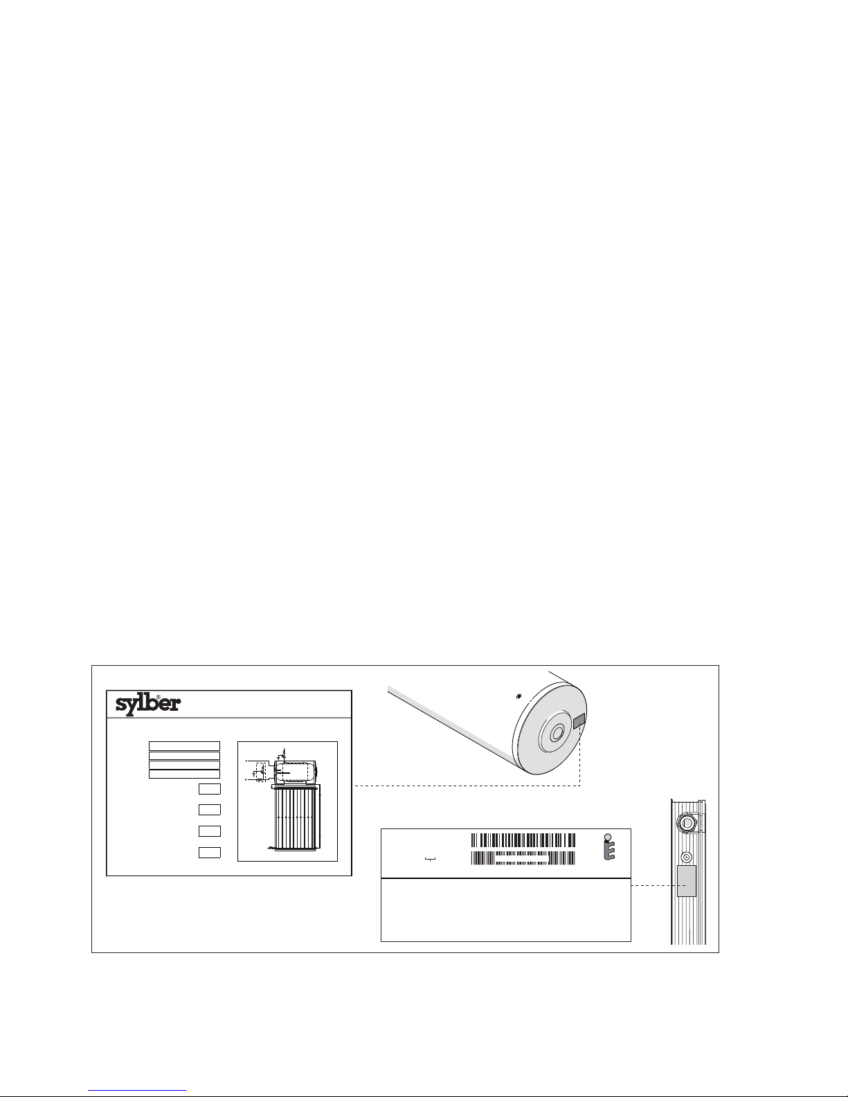
5 IDENTIFICATION
S
SN TI
systems are identified by:
CODICE : 20091464
TIPO : CP20TSS
S/N :
COLLETTORE SOLARE PIANO
DIMENSIONI: 1818X1048X70 mm
SUPERFICIE LORDA: 1,91 m
2
TEMPERATURA DI STAGNAZIONE: 192°C
SUPERFICIE DI APERTURA: 1,78 m
2
CONTENUTO LIQUIDO: 1,6 l
SUPERFICIE ASSORBITORE: 1,77 m
2
PESO A VUOTO: 34 kg LIQUIDO TERMOVETTORE:
ACQUA+GLICOLE PROPILENICO
MAX CONCENTRAZIONE GLICOLE: 50%
MAX PRESSIONE ESERCIZIO: 10 bar
FABBRICATO IN ITALIA
da Riello S.p.A.
20092486_E2
EN 12975
Certif. 011-7S2400F
13000000
BAR CODE 128B
Anno di produzione
SERIALE PROGRESSIVO
SISTEMA SOLARE A CIRCOLAZIONE NATURALE
NATURAL CIRCULATION SOLAR WATER HEATING SYSTEM
Serial N°
Mod.
bar
Anno
l
Cod.
Tipo/Type
bar
Year
Capacità bollitore
Storage cylinder capacity
Pressione di progetto acqua sanitaria
DHW circuit operating pressure
Pressione max circuito solare
Max solar heating circuit pressure
La protezione da sovratemperatura dipende dalla fornitura di acqua fredda sanitaria
Over
r - t
emperat
ure
prot
ection
requires an a
dequate supply of co
ld water
T067783GE
SYLBER
Via Risorgimento, 13
23900 Lecco (LC)
Storage cylinder data plate
Collector data plate
b
If these plates or any other means of clearly identifying the product are defaced, removed or lost, proper installation
and servicing may be rendered difficult.
Page 6
6
GENERAL
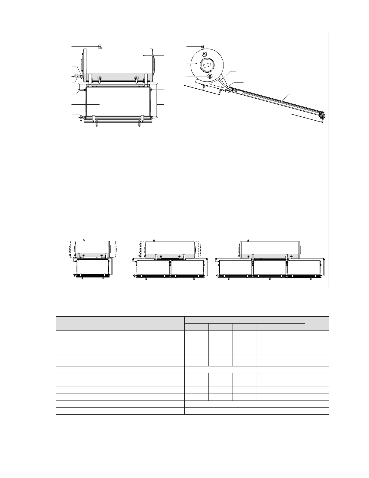
6 SYSTEM LAYOUT
11 11
8
2
7
4
7
1 5
2
1
4
3
6
10
12
9 (*)
Components
1 Solar collector/s
2 Storage cylinder
3 Mounting frame
Pipes and ttings
4 Collector outlet
5 Collector return
6 Plug
External connections
7 Domestic cold water inlet - 3/4”
8 Domestic hot water outlet - 3/4”
9 Domestic cold water inlet cock
10 Filling/drain cock
Safety devices
11 Primary circuit safety valve (2.5 bar)
12 Non-return valve - Secondary circuit safety valve (10
bar)
(*) (Not supplied. To be provided by installer.)
POSSIBLE CONFIGURATIONS
SN TI
150/1÷200/1
SN TI
220/2÷300/2
SN TI
300/3
7 TECHNICAL SPECIFICATIONS
Description
SN TI
150/1 200/1 220/2 300/2 300/3
Collector surface area 1,91 x 1 1,91 x 1 1,91 x 2 1,91 x 2 1,91 x 3
m
2
x n.
of pan.
Exposed area 1,78 x 1 1,78 x 1 1,78 x 2 1,78 x 2 1,78 x 3
m
2
x n.
of pan.
Absorption area 1,77 x 1 1,77 x 1 1,77 x 2 1,77 x 2 1,77 x 3
m
2
x n.
of pan.
Stagnation temperature 192 °C
Storage cylinder capacity 153 202 223 278 278 l
Magnesium anode 22 x 300 22 x 300 22 x 300 22 x 400 22 x 400 Ø x mm
Heat transfer liquid capacity 8,5 13,6 16,3 20,3 22,2 l
Maximum wind and snow load 1900 1900 1500 1900 1500 Pa
DHW circuit safety valve operating pressure 10 bar
Solar collector circuit safety valve operating pressure 2,5 bar
Page 7
7
GENERAL
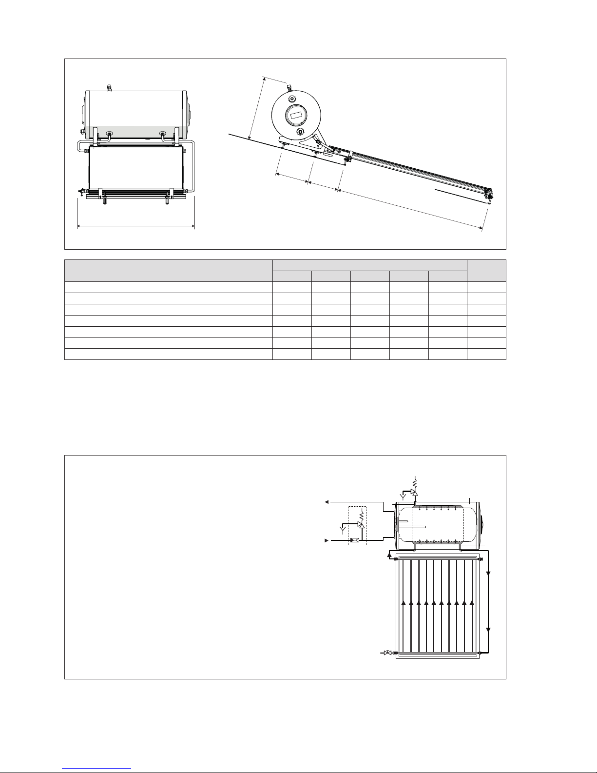
8 OVERALL DIMENSIONS AND WEIGHTS
L
H
P2
P1
P
Description
SN TI
150/1 200/1 220/2 300/2 300/3
Empty weight 94 122 143 193 200 kg
Full weight 256 338 382 491 500 kg
L 1300 1300 2410 2410 3510 mm
P 270 270 360 360 360 mm
P1 1965 1965 1619 1619 1619 mm
P2 - - 332 332 332 mm
H 720 720 720 720 720 mm
9 WATER CIRCUIT
UAC
Domestic hot water outlet
EAF
Domestic cold water inlet
1
Primary (solar collector) circuit safety valve (2.5 bar)
2
Non-return valve - safety valve of secondary (DHW)
circuit (10 bar)
3
Storage cylinder
4
Collector
5
DHW tank (secondary circuit)
6
Primary circuit
7
Temperature sensor socket
8
Magnesium anode
9
Primary circuit filling/drain cock
10
Insulation
CWI
HWO
1
2
3
5
6
6
4
heat exchange
heat exchange
9
8
7
10
Page 8
8
INSTALLER
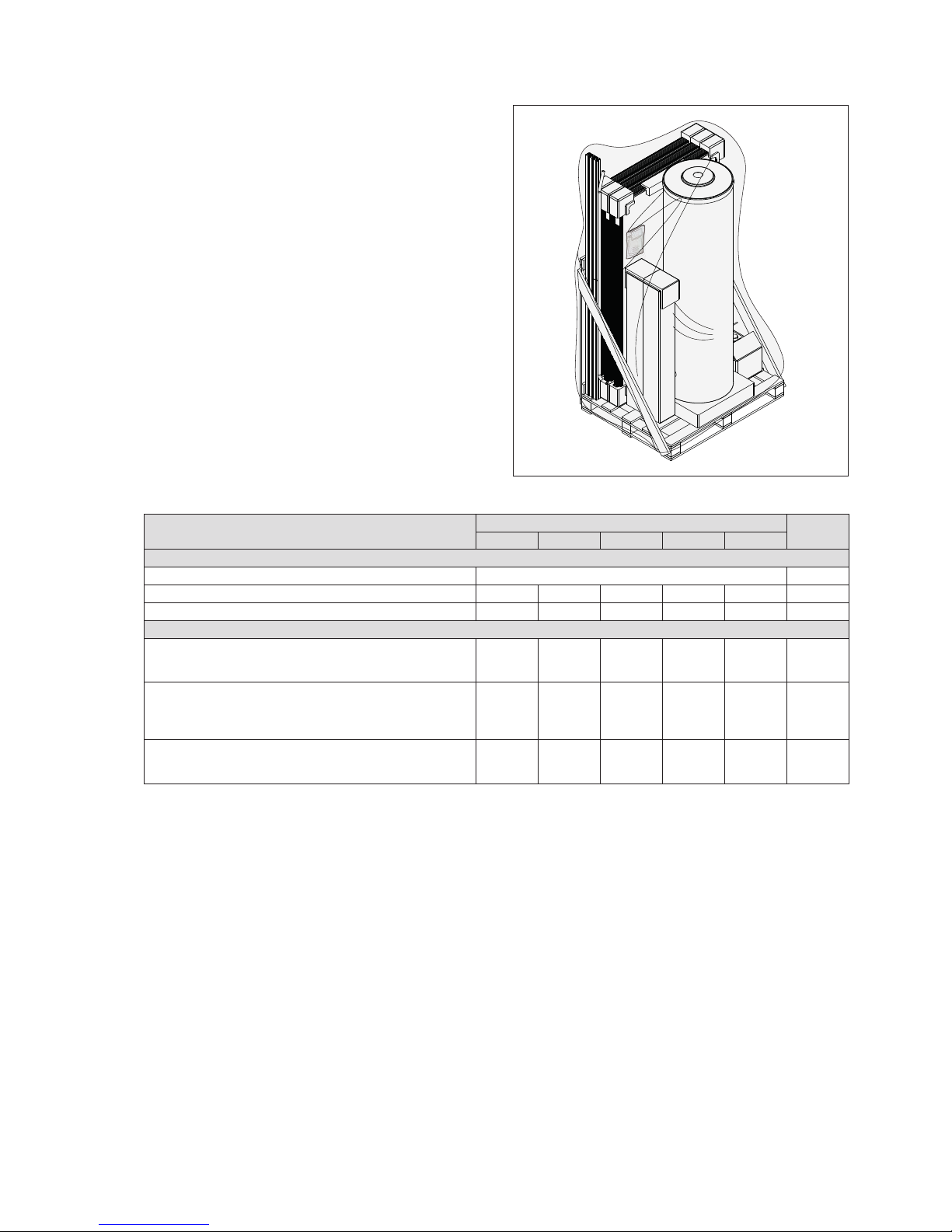
10 UNPACKING THE PRODUCT
Contents of packing:
- Solar collector/s
- Storage cylinder
- Box of accessories containing fittings and a container
of glycol anti-freeze
- Mounting kit for flat roofs (see the assembly section for
details of kit contents).
A plastic pouch containing:
- Instruction manual
- Bar code label
- Serial number plate.
b
This instruction manual is an integral part of the
SN
TI
system. Once located, read it thoroughly and
keep it safe.
b
A protective lm is applied to the glass of the solar
collector. On completion of installation, only remove
this lm if you are going to put the system into service
immediately.
Description
SN TI
150/1 200/1 220/2 300/2 300/3
WEIGHT
Total weight of supply See the transport document kg
COLLECTOR/S package 34 34 3 x 34 3 x 34 4 x 34 kg
STORAGE CYLINDER package 62 76 84 106 116 kg
DIMENSIONS
Total supply package
2034 x
1246 x
770
2034 x
1246 x
770
2053 x
1246 x
870
2160 x
1250 x
870
2174 x
1246 x
870
mm
COLLECTOR/S package
1866 x
1200 x
95
1866 x
1200 x
95
3 x
(1865 x
1200 x
95)
3 x
(1865 x
1200 x
95)
4 x
(1865 x
1200 x
95)
mm
STORAGE CYLINDER package
1250 x
600 x
600
1250 x
600 x
600
1250 x
600 x
600
2050 x
600 x
600
2050 x
600 x
600
mm
Installer
Page 9
9
INSTALLER
11 HANDLING
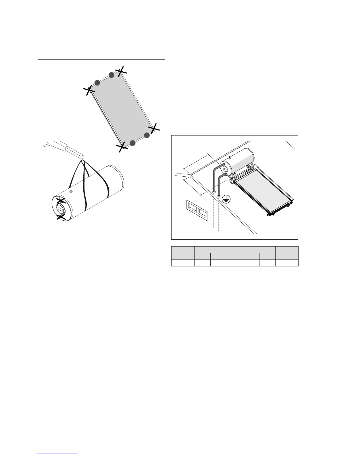
Hold solar collectors at the points shown (A) to move them.
Lift and move the storage cylinder in a horizontal position.
Make sure that the slings and lifting gear used are suitable
for the weight.
A
A
A
A
a
Do not lift the solar collector by its water fittings.
a
Do not lift the storage cylinder by its water fittings.
b
Wear suitable personal protective equipment and use
suitable safety devices.
12 PREPARING FOR INSTALLATION
Select the best possible orientation for the solar collectors
(ideally facing south). Avoid positions that are shaded by
plants, trees, buildings or hills, etc. during the day.
Maintain the minimum distance (A) between the system
and the edge of the roof.
Remove all gravel and detritus from the surface on which
the system is to be installed.
The mounting kit must not be used to install other superstructures. It is designed only for use with S solar water
heating systems.
The installation of a solar water heating system modifies
the existing structure of the roof. Verify the suitability of all
roof elements and if necessary adapt them to avoid leaks
or damage by wind and/or snow loads.
> A
> A
SN TI
U.M.
150/1 200/1 220/2 300/2 300/3
A 1 1 1,5 1,5 1 m
Page 10
10
INSTALLER
13 ASSEMBLY
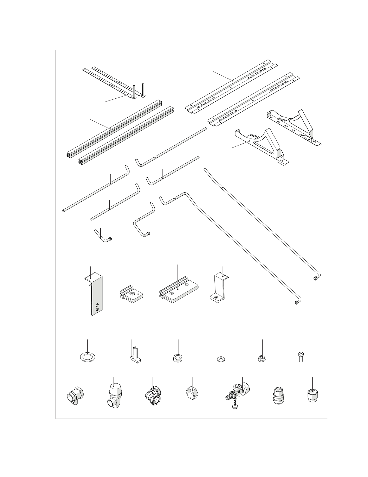
Start installing the system by assembling the mounting frame for sloping roofs. To do so, follow the instructions given
below.
5
6
7
13
2 3
18
14 4 8 11 9 12
19 20 17 1521 16
1 10
23
24
25
27
28
29
26
22
Page 11

11
INSTALLER
CONTENTS OF MOUNTING KIT
Description
SN TI
150/1 200/1 220/2 300/2 300/3
1 Clamp 2 2 4 4 6
2 Collector fixing bracket 2 2 4 4 6
3 Collector fixing bracket 2 2 4 4 6
4 Rectangular head screw 4 4 8 8 12
5 Mounting brackets 2 2 2 2 2
6 Profiles 2 2 2 2 2
7 Support bars 2 2 2 2 4
8 M12 nut 12 12 24 24 36
9 M8 flanged nut 12 12 24 24 36
10 Join clamps - - - - 2
11 M12 washer 12 12 24 24 36
12 M8 screw 14 14 28 28 42
13 Stud strips 6 6 6 6 6
14 1" seal 4 4 6 6 8
15 1/2" F x 1" M straight union 1 1 1 1 1
16 3/4" straight union 2 2 2 2 2
17 Elbow union - - 2 2 2
18 Collector plug 1 1 1 1 1
19 10 bar safety valve 1 1 1 1 1
20 2.5 bar safety valve 1 1 1 1 1
21 Cock 1 1 1 1 1
22 150-200 return pipe 1 1 - - 23 150-200 flow pipe 1 1 - - 24 200-300 return pipe - - 1 1 25 200-300 flow pipe - - 1 1 26 Additional flow pipe - - 1 1 1
27 Additional return pipe - - 1 1 1
28 300 return pipe - - - - 1
29 300 flow pipe - - - - 1
Page 12
12
INSTALLER
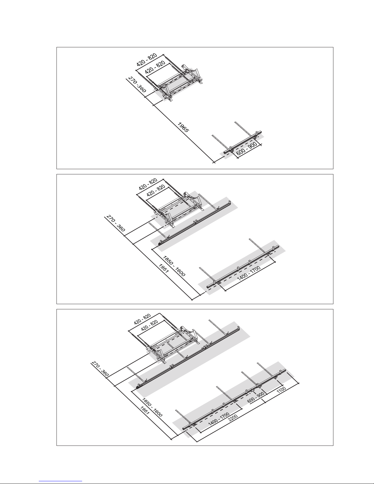
STEPS VALID FOR ALL MODELS
- Mark the anchoring points
b
Check that the marks are square.
150/1
200/1
220/2
300/2
300/3
Page 13
13
INSTALLER
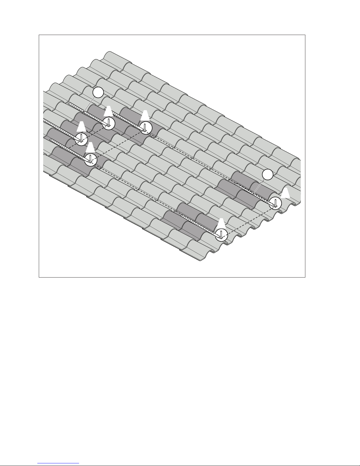
- Position the stud strips (13) in the concave section of the tiles. Maintain the distances specified in the previous point
between the studs “A”
A
A
A
A
A
A
13
13
Page 14
14
INSTALLER
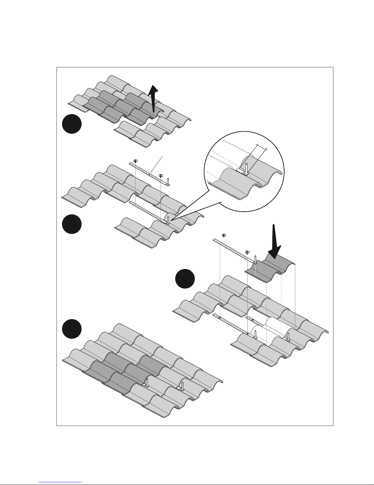
Fix the front and rear stud strips to the roof. Secure each strip at a minimum of two points, and check for tightness. The
screws “V” are NOT SUPPLIED and must be provided on installation. Only use screws that are suitable for the characteristics of the roof.
Proceed as follows:
- Remove the tiles
- Fit the stud strip (13) in close contact with the roof, minimising the distance "D". If necessary bend the strip as needed
- Replace the roof tiles
1
2
V
V
D
3
V
V
4
13
Page 15
15
INSTALLER
STEPS VALID FOR THE FOLLOWING MODELS: 150/1 - 200/1
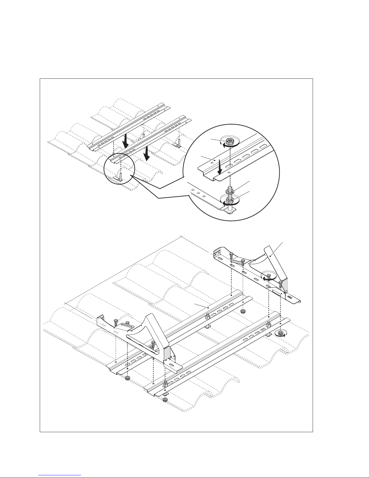
Fix the profiles to the front studs.
Proceed as follows:
- Screw the nuts (8) and washers (11) as far down as possible over the studs
- Fit the profiles (6) over the studs
- Fix the profiles in place with the nuts (8)
Fix the mounting brackets (5) to the profiles (6) with the M8 screws (12) and nuts (9).
M12
M12
860 mm 150/1 - 200/1 - 220/2
1040 mm 300/2 - 300/3
M8
M8
8
8
6
6
5
11
Page 16
16
INSTALLER
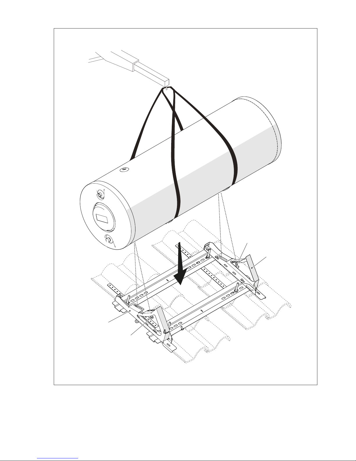
Position the storage cylinder on the mounting brackets (5) and fix it in place with the M8 bolts (12).
5
12
12
5
Page 17
17
INSTALLER
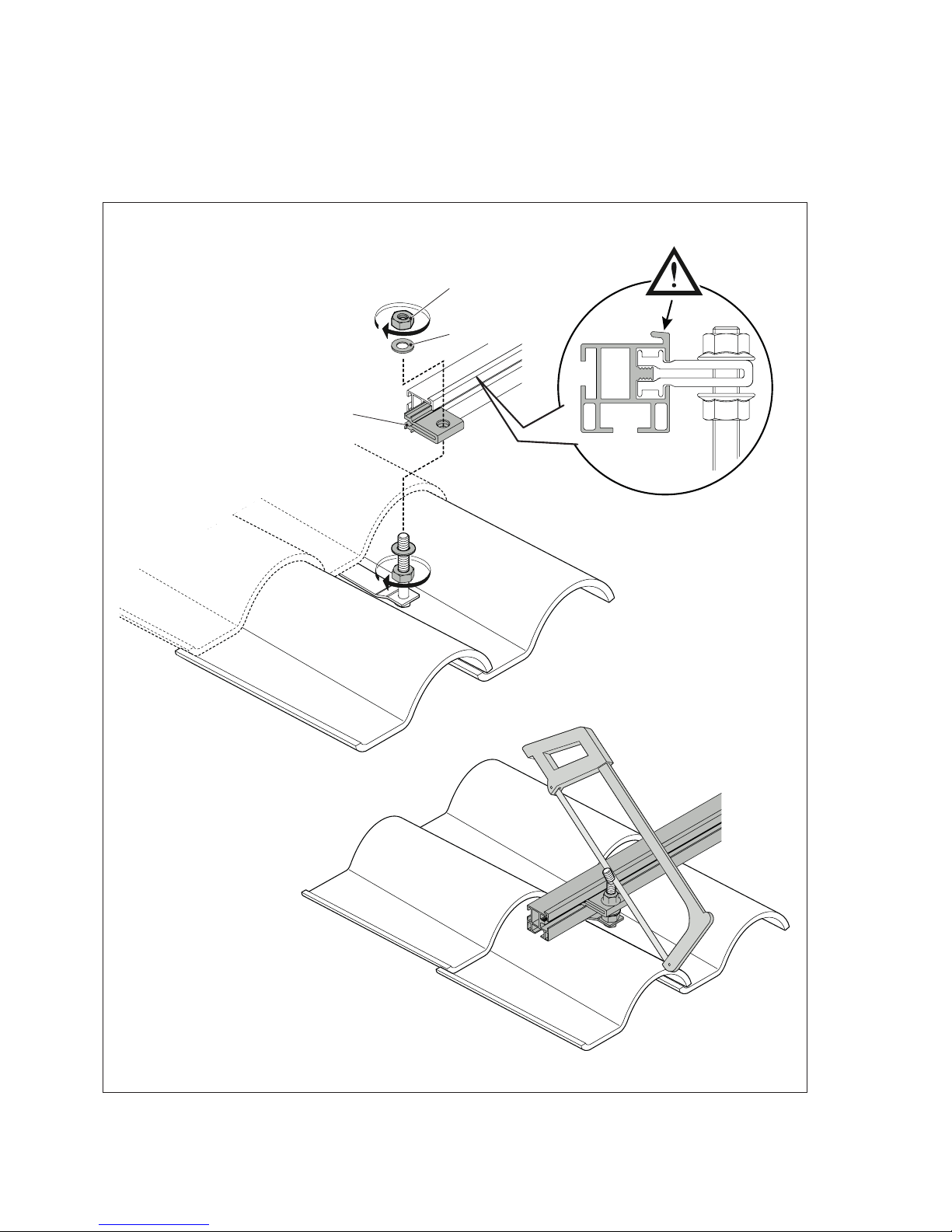
Fit the support bar to the rear studs.
Proceed as follows:
- Screw the nuts (8) and washers (11) as far down as possible over the studs
- Fit the clamps (1) to the studs on the strips
- Engage the support bar (7) in the clamps (1)
- Fix the support bar (7) in place with the nuts (8) of the clamps (1)
Adjust the clamps to the same height and fix them in place (about 20-30 mm from the top of the tiles), then saw off the
protruding lengths of stud.
M12
M12
8
1
11
Page 18
18
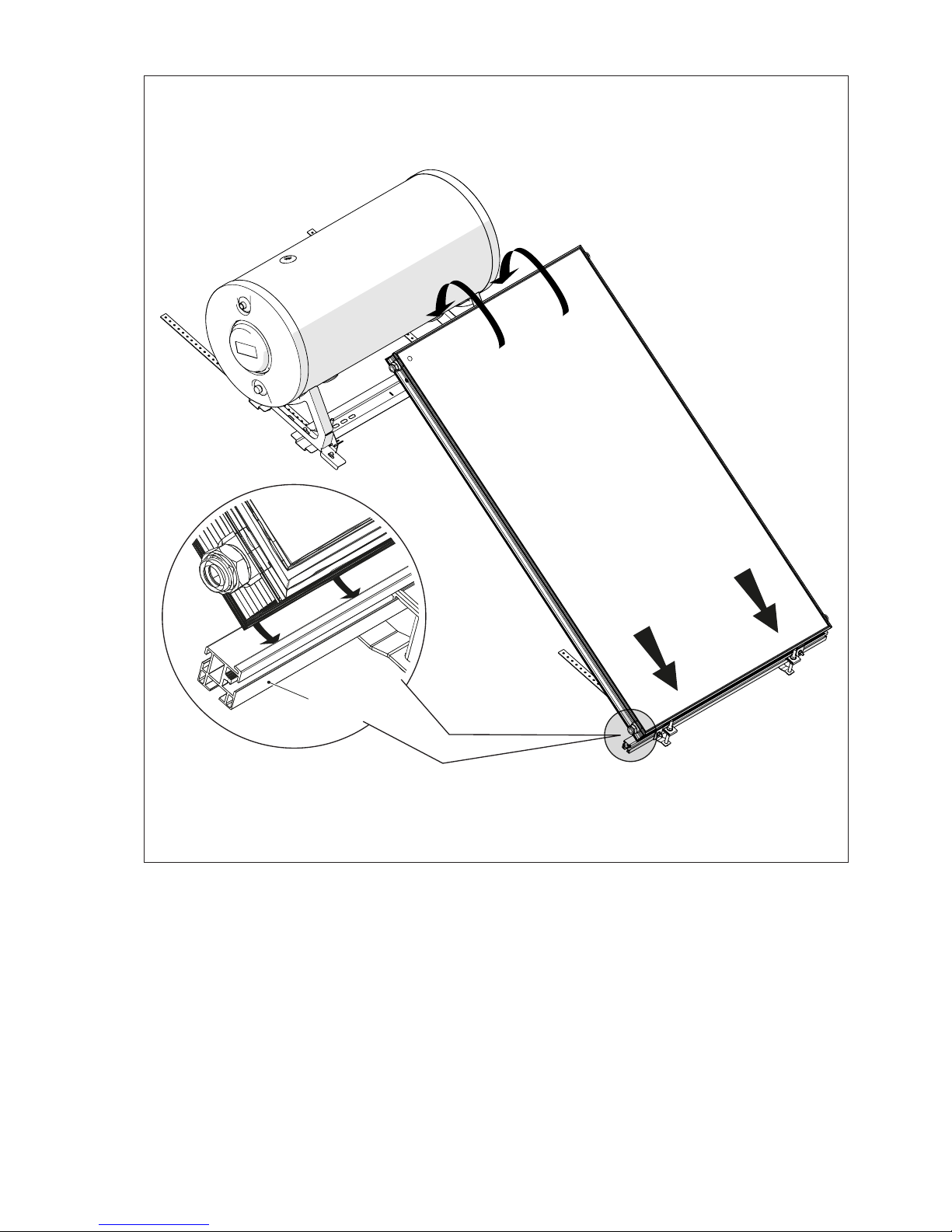
INSTALLER
Position the collector, pivoting it on the support bar (7).
7
Page 19
19
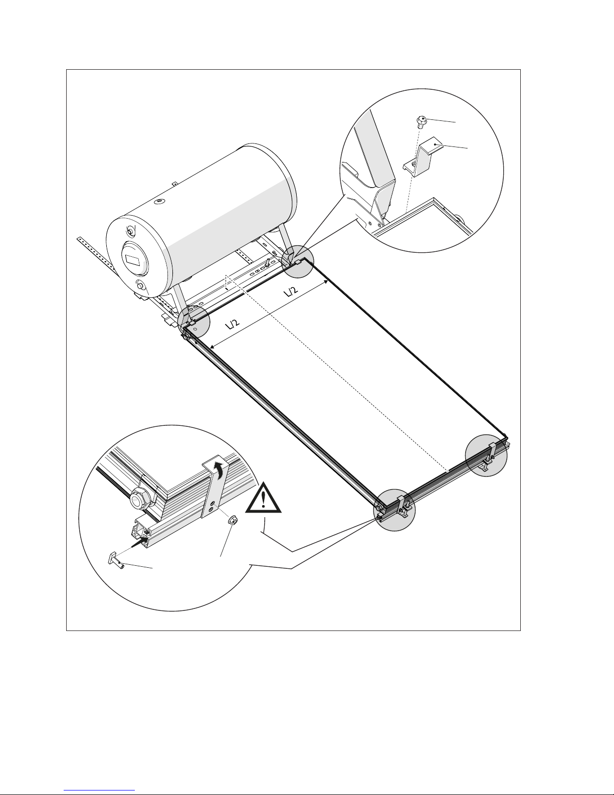
INSTALLER
Secure the collector with the top fixing brackets (3).
Make the water connections.
Secure the collector with the bottom fixing brackets (2), using the top hole.
3
12
4
9
Page 20
20
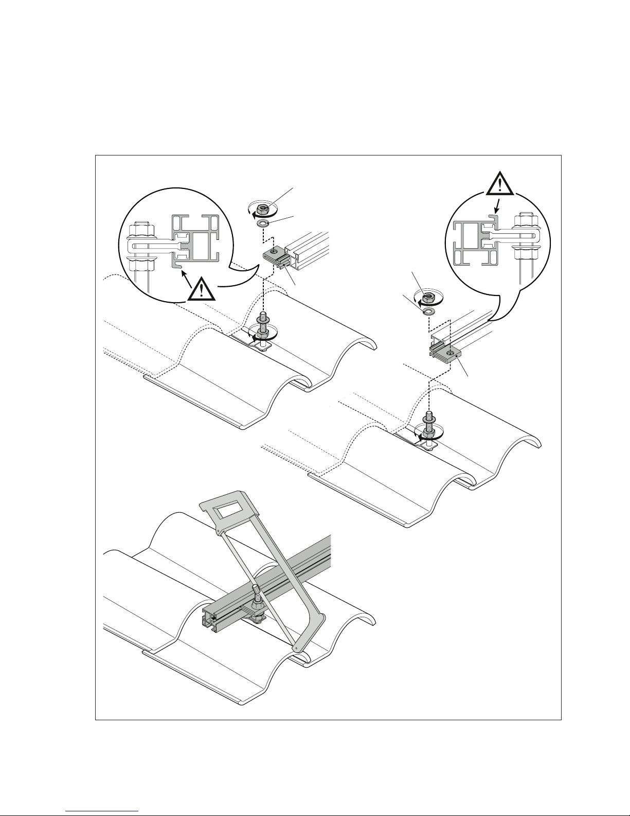
INSTALLER
STEPS VALID FOR THE FOLLOWING MODELS: 220/2 - 300/2 - 300/3
Fit the support bars to the front and rear studs.
Proceed as follows:
- Screw the nuts (8) and washers (11) as far down as possible over the studs
- Fit the clamps (1) to the studs on the strips
- Engage the support bar (7) in the clamps (1)
- Fix the support bar (7) in place with the nuts (8) of the clamps (1)
Adjust the clamps to the same height and fix them in place (about 20-30 mm from the top of the tiles), then saw off the
protruding lengths of stud.
M12
M12
M12
M12
11
1
1
8
8
11
Page 21
21
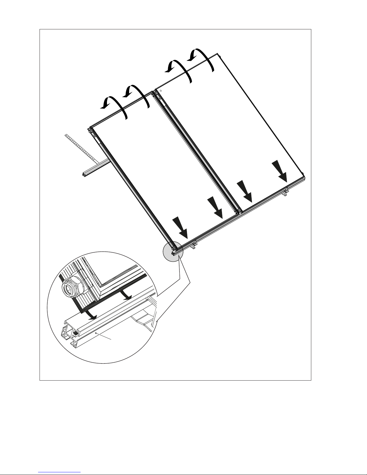
INSTALLER
Position the collector, pivoting it on the support bar (7).
7
Page 22
22
INSTALLER
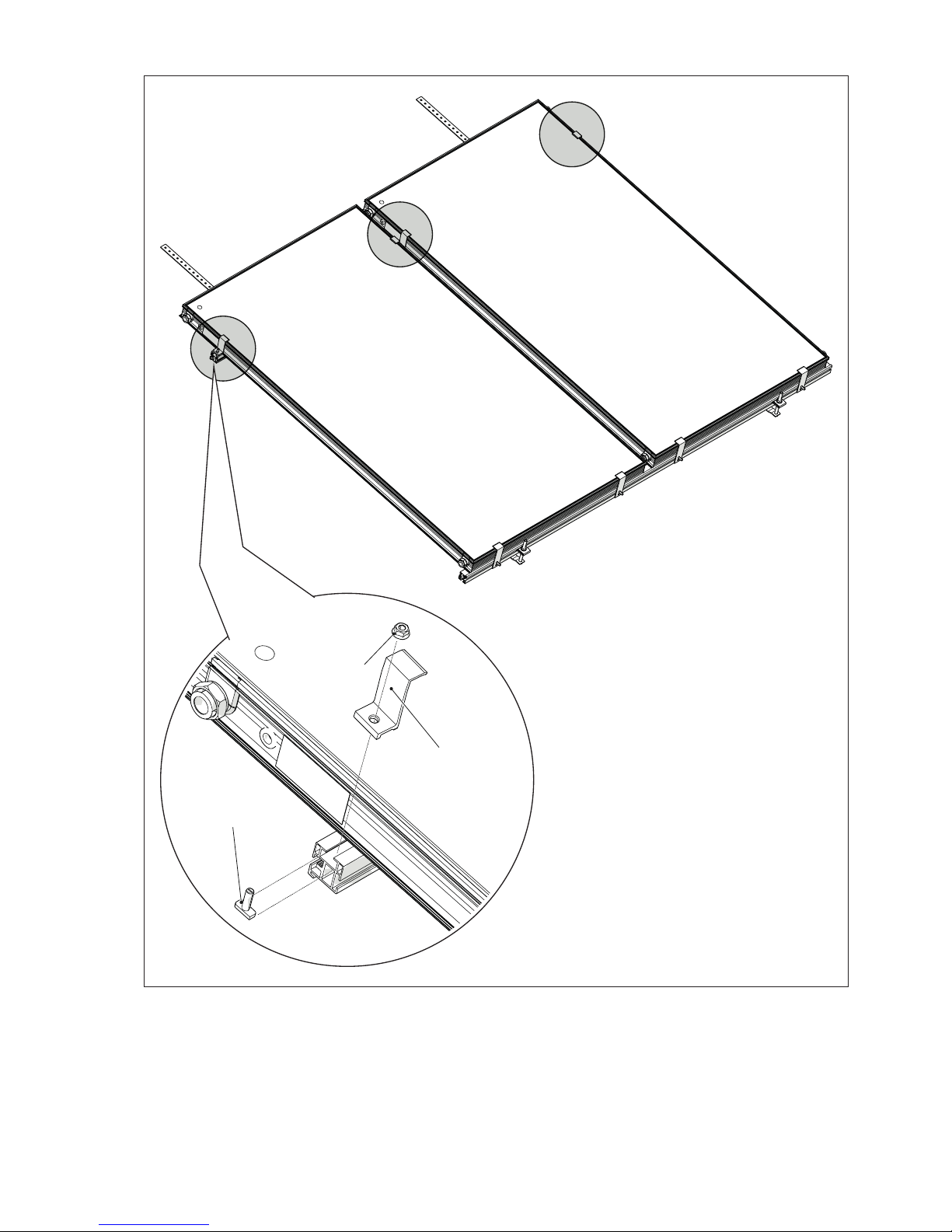
Secure the collector with the top fixing brackets (3).
3
9
4
Page 23
23
INSTALLER
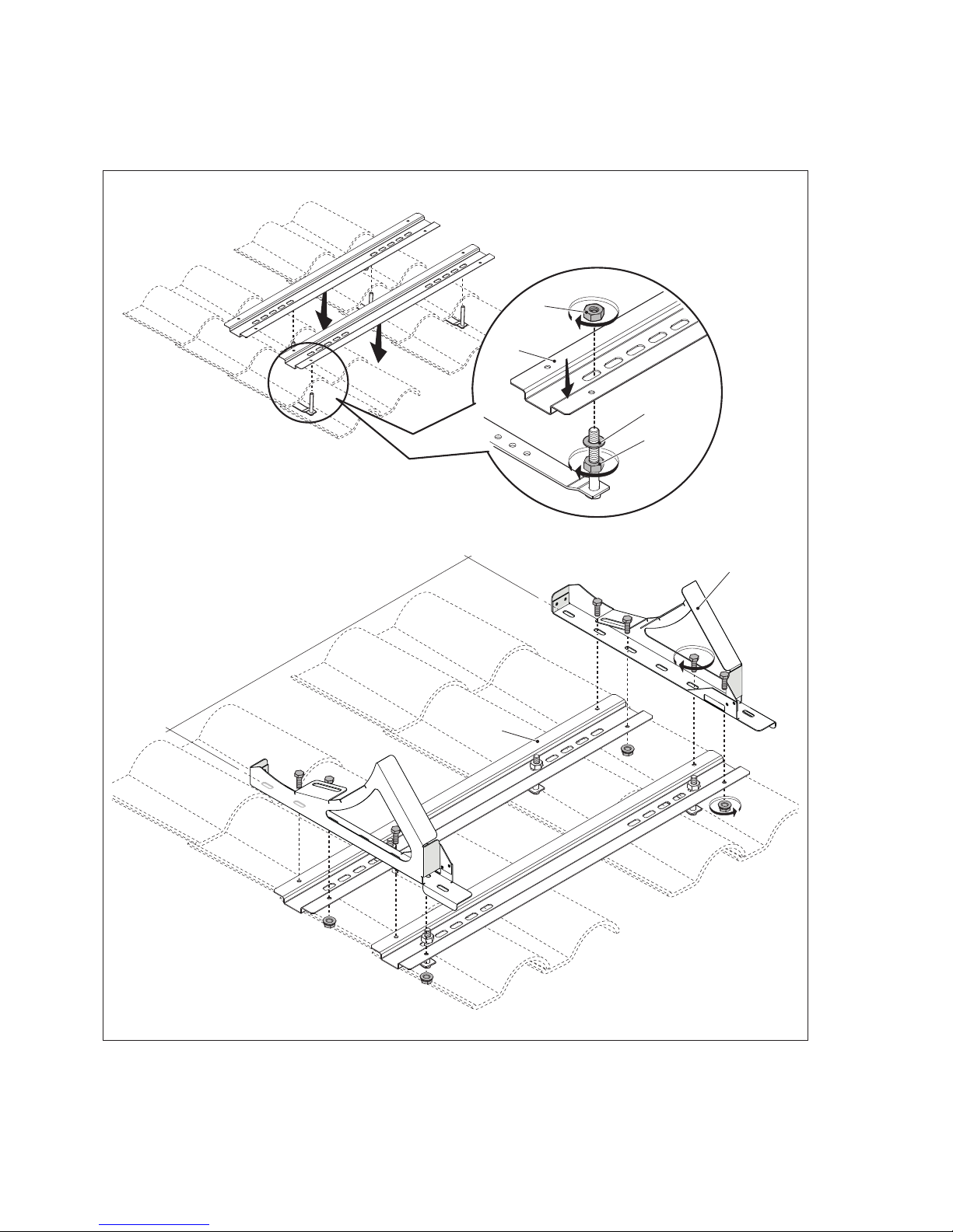
Fix the profiles to the front studs.
Proceed as follows:
- Screw the nuts (8) and washers (11) as far down as possible over the studs
- Fit the profiles (6) over the studs
- Fix the profiles in place with the nuts (8)
Fix the mounting brackets (5) to the profiles (6) with the M8 screws (12) and nuts (9).
M12
M12
860 mm 150/1 - 200/1 - 220/2
1040 mm 300/2 - 300/3
M8
M8
8
8
6
6
5
11
Page 24
24
INSTALLER
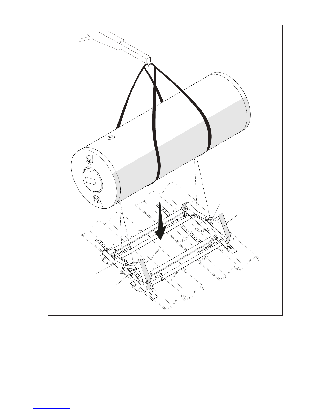
Position the storage cylinder on the mounting brackets (5) and fix it in place with the M8 bolts (12).
5
12
12
5
Page 25
25
INSTALLER
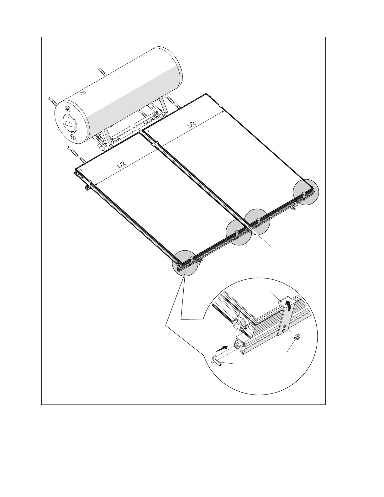
Make the water connections.
Secure the collector with the bottom fixing brackets (2), using the top hole.
4
9
2
Page 26
26
INSTALLER
STEPS VALID FOR ALL MODELS
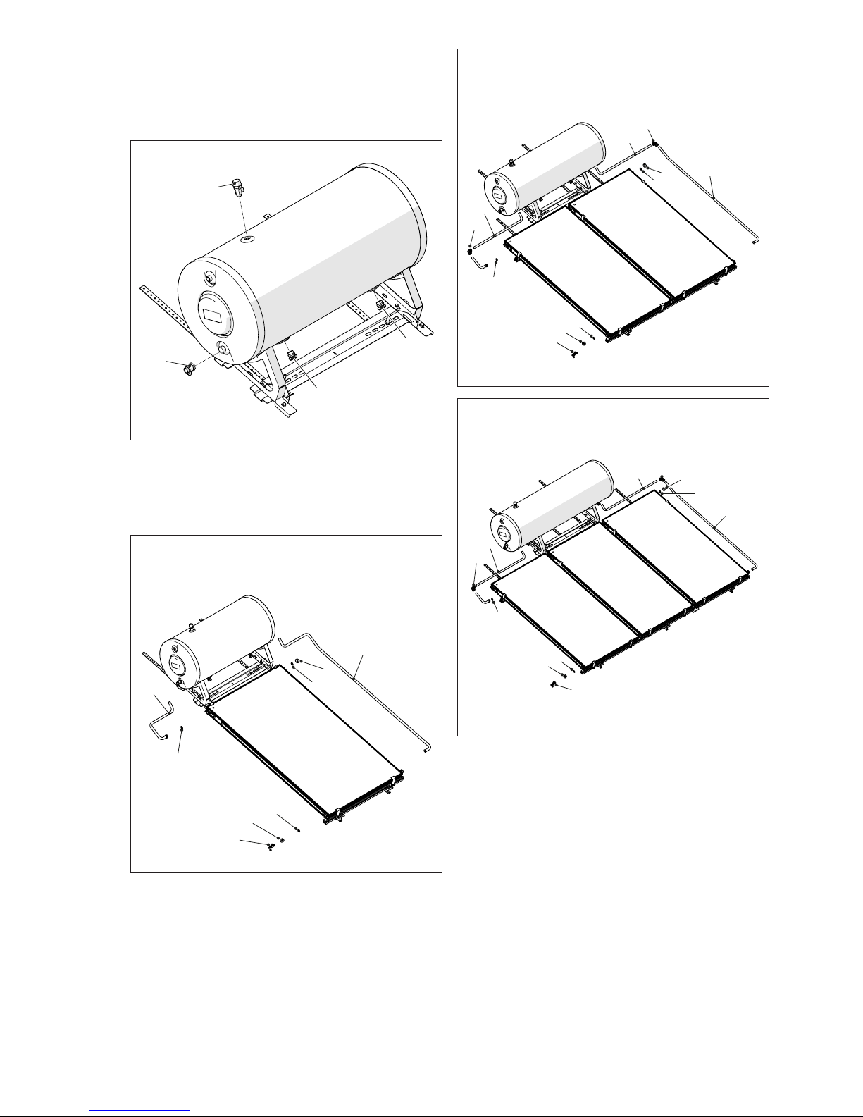
Make the following connections:
- 2.5 bar safety valve (20)
- 10 bar safety valve (19)
- straight flow and return unions (16)
20
19
16
16
Complete the collector water connections:
- flow pipes
- return pipes
- drain cock
- plug
150/1
200/1
14
22
21
15
14
18
14
23
220/2
300/2
14
21
15
14
26
25
17
18
14
17
25
300/3
14
21
15
14
26
17
29
18
14
29
17
Page 27
27
INSTALLER
Make sure that you comply with all applicable lightning
protection and building potential compensation legislation.
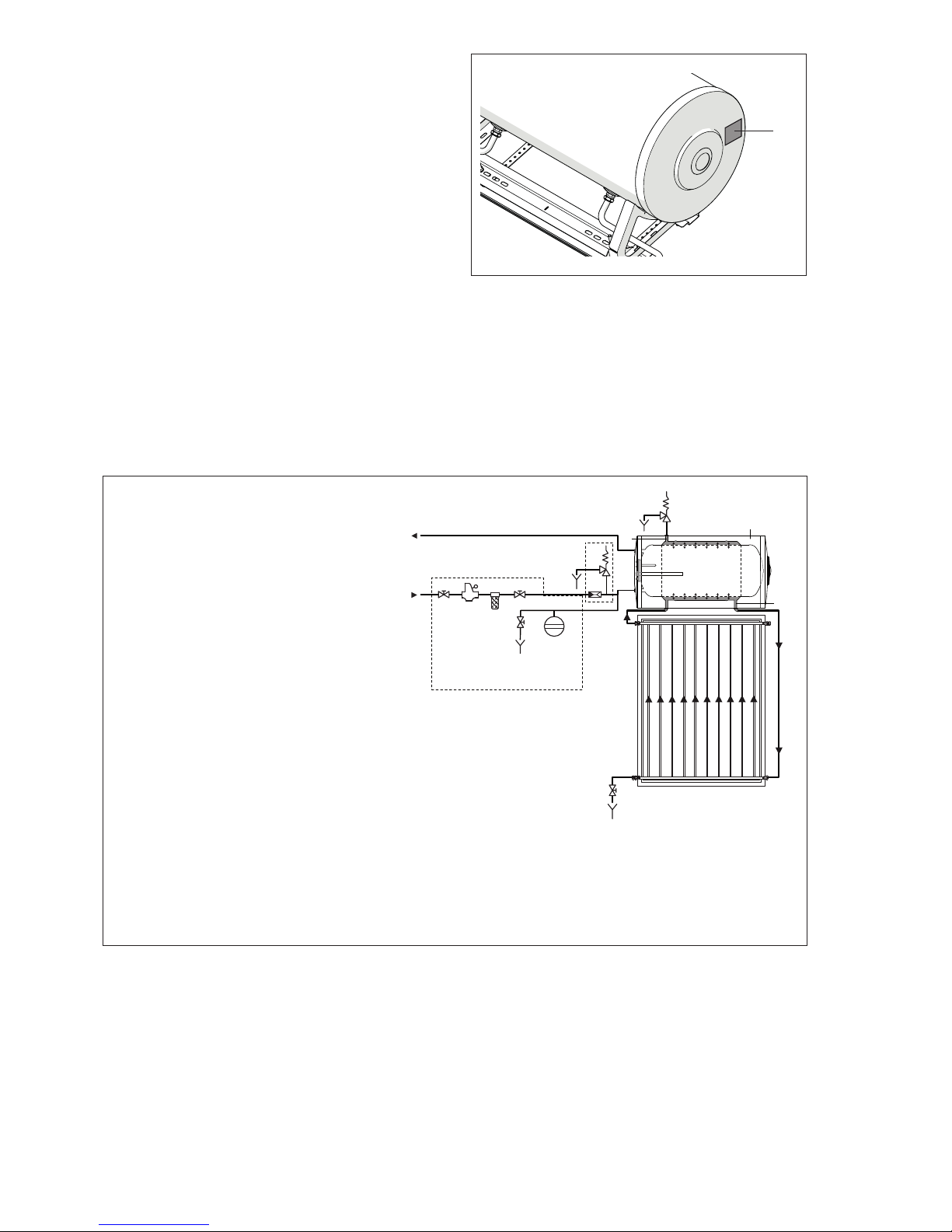
On completion of assembly, make sure that the S solar water heating system is perfectly stable, then remove
the protective film from the storage cylinder. Apply the
data plate (1) and the S label to the storage cylinder.
a
Never attempt to install the system without using the
personal protection equipment and without following the safety precautions specified by applicable
occupational safety standards.
1
b
A protective film is applied to the glass of the solar collector to protect the absorber against solar irradiation and
prevent the solar collector from becoming too hot if it is not going to be put into service immediately.
Fill the system,
but do not remove the lm until you are ready to put the system into service.
Take care when removing the film as it may
be electrostatically charged. Do not leave the protective film in place for longer than 12 months. Once removed,
the protective film cannot be re-used. Dispose of the protective film in compliance with legislation governing the
disposal of PVC.
14 SYSTEM WATER CONNECTIONS
UAC
Domestic hot water outlet (Ø 3/4”)
EAF
Domestic cold water inlet (Ø 3/4”)
1
Primary (solar collector) circuit safety valve
(2.5 bar)
2
Non-return valve - safety valve of secondary
(DHW) circuit (10 bar)
3
Storage cylinder
4
Collector
5
DHW tank (secondary circuit)
6
Primary circuit
7
Temperature sensor socket
8
Magnesium anode
9
Primary circuit filling/drain cock
10
Cock
11
Insulation
12
DHW circuit expansion vessel
13
Pressure reducer
14
Water softener filter
15
Drain
CWI
HWO
heat exchange
heat exchange
Connections to be
made by the installer
1
10
10
10
12
13
14
15
15
15
9
15
2
3
5
8
6
6
4
11
7
The water supply circuit must permit the storage cylinder to be filled and emptied in safety. Shut-off valves must therefore
be easily accessible to the user and the operation of emptying the storage cylinder must not create any risk of flooding
or other damage.
b
All water pipe connections must conform to applicable standards.
b
The operating pressure limits specified on the data
plate must never be exceeded. It may therefore be
necessary to fit a pressure reducer.
b
A thermal mixing valve must always be connected
to the hot water outlet to control the temperature of
hot at the taps.
b
The point through which the water pipes enter the
building must be rain-proof and damp-proof.
Page 28
28
INSTALLER
b
All shut-off cocks and drain cocks must be easily
accessible. Make sure that the end user fully understands how they function.
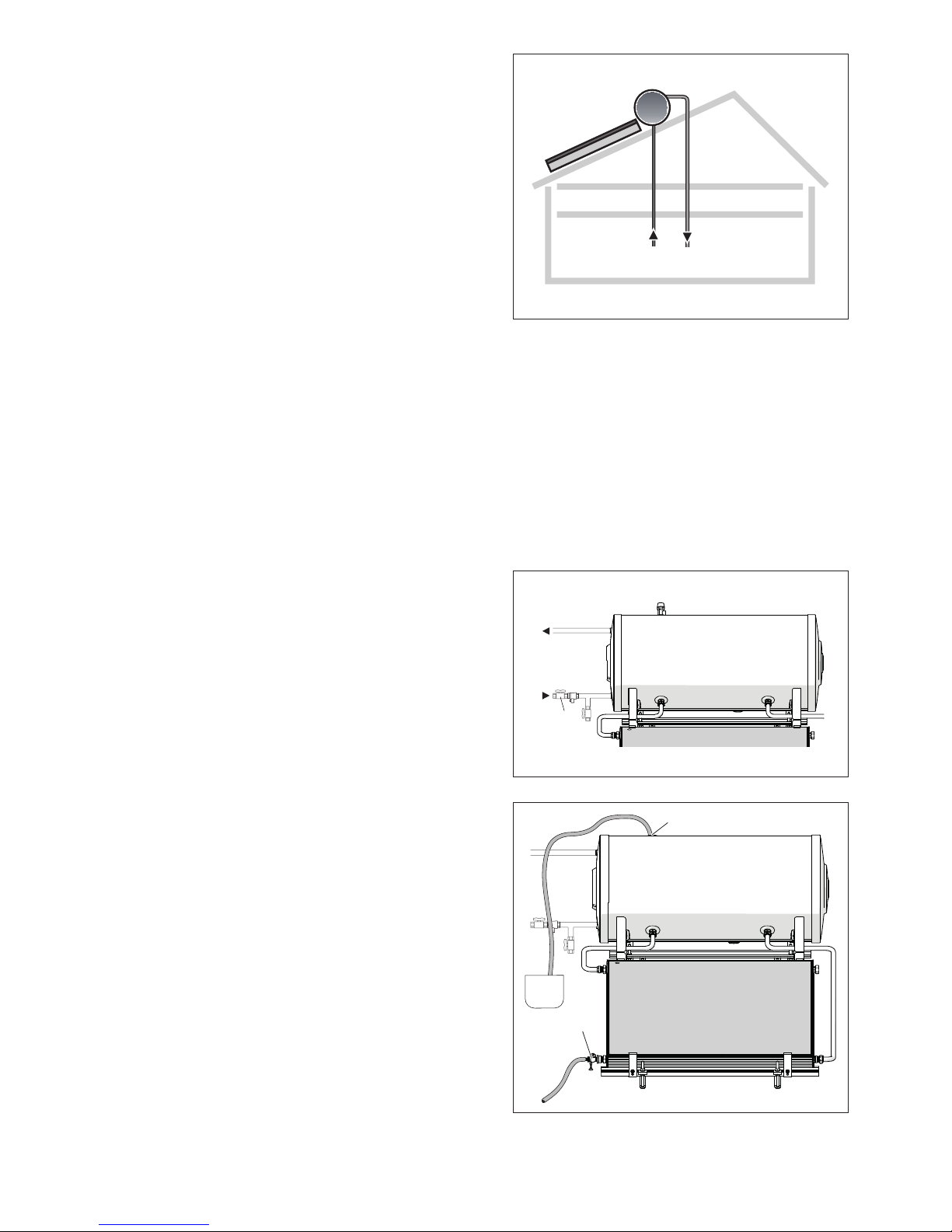
Shut-off and drain cocks
15 PREPARING FOR INITIAL STARTUP
Proceed as follows to fill the primary and secondary circuits.
- Fill the DHW tank.
- Flush out the solar collector circuit.
- Fill the solar collector circuit.
b
Fill the DHW tank before filling the solar collector
circuit.
b
Only fill the solar collector circuit when the collectors are cold.
FILLING THE DHW TANK
- Open and leave open the cock (5) for the domestic cold
water inlet (CWI).
- Open a hot water tap and fill the storage cylinder with
cold water from the mains supply. When water starts
coming out of the hot water tap, leave it run until you
obtain an even flow then close the tap. The DHW tank
is now full.
FLUSHING THE SOLAR COLLECTOR CIRCUIT
Carefully check all connections and unions for leaks before filling the system with the water and glycol mix. Use
the following procedure to test for water tightness. The
same procedure can also be used to flush out the circuit
to remove any residues.
- Connect the hose union on the filling/drain cock (1) to a
cold water tap using a length of hose pipe.
- Connect the union (2) on the storage cylinder to a drain.
- Open the cock (1) and the cold water tap and leave water flow into the solar collector circuit for a few minutes.
- Close the cold water tap and the cock (1).
- Check all connections and unions for leaks.
EAF
Sc
UAC
5
2
1
Page 29
29
INSTALLER
FILLING THE SOLAR COLLECTOR CIRCUIT
Heat transfer liquid
The anti-freeze supplied contains non-toxic, biodegradable and environmentally friendly propylene glycol. Mix the
propylene glycol with water (preferably demineralised).
Establish the necessary concentration of propylene glycol using the table alongside on the basis of the temperatures for which anti-freeze protection is required.
b
Only use the products listed in the S Catalogue
to top up the circuit.
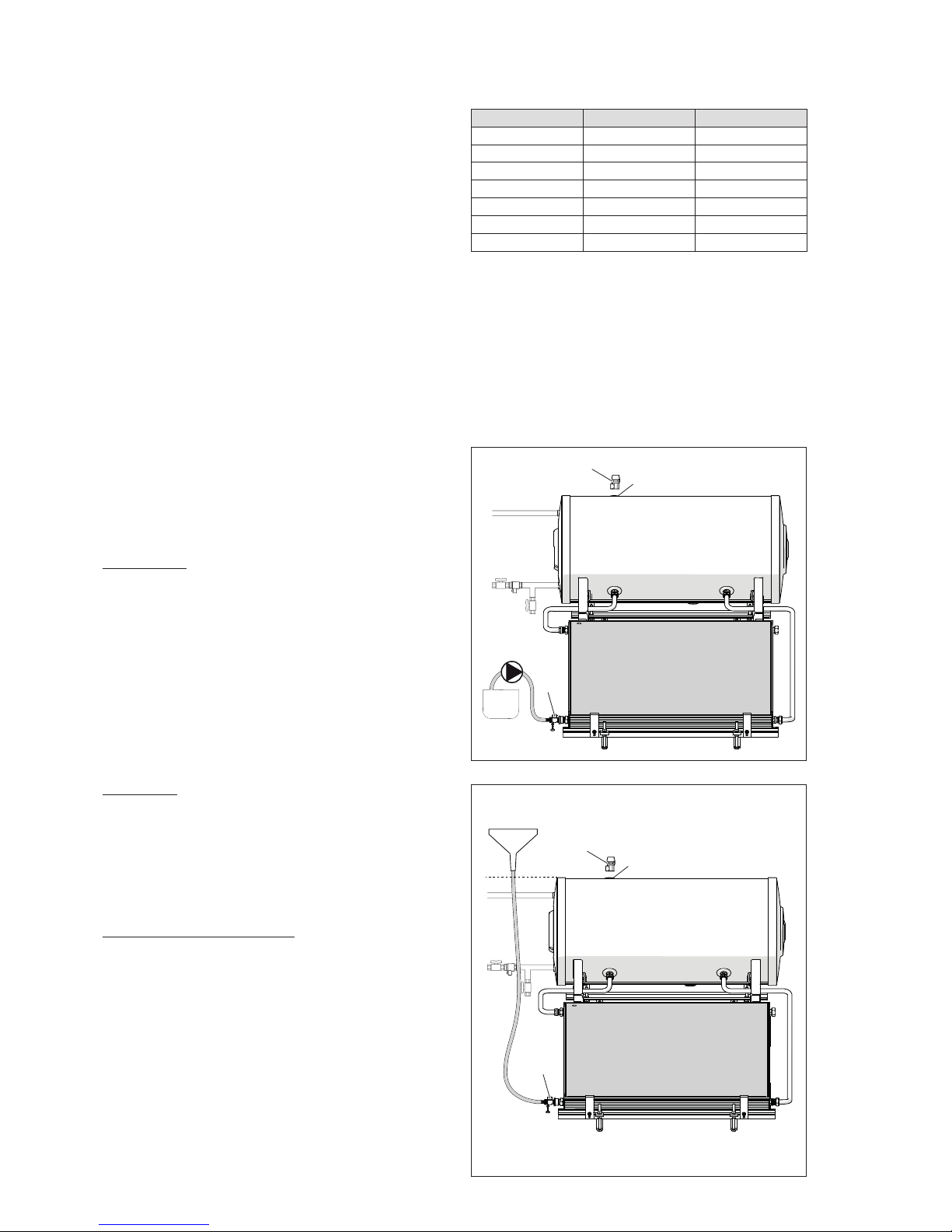
Pressure and gravity lling
- Premix a sufficient volume of water and glycol solution
in a suitable container, selecting the right concentration
according to the table above.
Pressure
filling
- Use lengths of rubber hose to connect a pump between
the container and the hose union on the filling/drain
cock (1). Open the cock.
- Start up the pump and fill the solar heating circuit until
the heat transfer liquid starts to flow out of the fitting (2)
at the top of the storage tank.
Gravity
filling
- Use a length of rubber hose to connect the container to
the filling/drain cock (1). Open the cock.
- Fill the solar heating circuit under gravity until the heat
transfer liquid starts to flow out of the fitting (2) at the top
of the storage tank.
When the storage cylinder is full:
- Close the cock (1).
- Fit the safety valve (3) to the fitting (2).
Anti-freeze Temperature Density (20 °C)
55% -40 °C 1,048 kg/dm
3
50% -32 °C 1,045 kg/dm
3
45% -26 °C 1,042 kg/dm
3
40% -21 °C 1,037 kg/dm
3
35% -17 °C 1,033 kg/dm
3
30% -14 °C 1,029 kg/dm
3
25% -10 °C 1,023 kg/dm
3
2
1
3
2
1
3
Page 30
30
TECHNICAL ASSISTANCE CENTRE
16 INITIAL STARTUP
Checks and preparations for initial start-up
Fill the storage cylinder with (potable) water.
Fill the solar collector circuit.
Make sure that the domestic cold water inlet
cock is open.
Make sure that the safety valves are functio-
ning.
Check the system for leaks.
Check the concentration of the anti-freeze.
Uncover the solar collectors and clean them
if necessary.
Make sure that the system is securely fixed
to the mounting frame.
Make sure that the roof does not leak.
Inspect the insulation.
17 MAINTENANCE
b
The solar water heating system must be serviced periodically by S’s Technical Assistance Centre or by a qualified heating engineer.
b
The system should be serviced at least once a year, ideally in the autumn.
b
Check the condition of the magnesium anode.
Visually inspect the collectors for damage/
dirt.
Visually inspect the storage cylinder.
Visually inspect the mounting frame and
roof anchor points.
Inspect the insulation.
Make sure that the roof does not leak.
Make sure that the safety valves are functio-
ning.
Check the system for leaks.
Check the concentration of the anti-freeze.
Check the pH of the anti-freeze with litmus
paper.
Topping up or changing the heat transfer
liquid
Clean inside the storage cylinder (every 2
years or more frequently in hard water/high
temperature areas)
Checking the heat transfer liquid
- Use an instrument like a refractometer or densimeter to check the density of the anti-freeze. If the value is below that
necessary to protect the system at the minimum temperature selected, replace the heat transfer liquid or add anti-freeze.
- Use litmus paper to check the pH (nominal value approx. 7.5). If the measured value is below 7, change the heat transfer liquid.
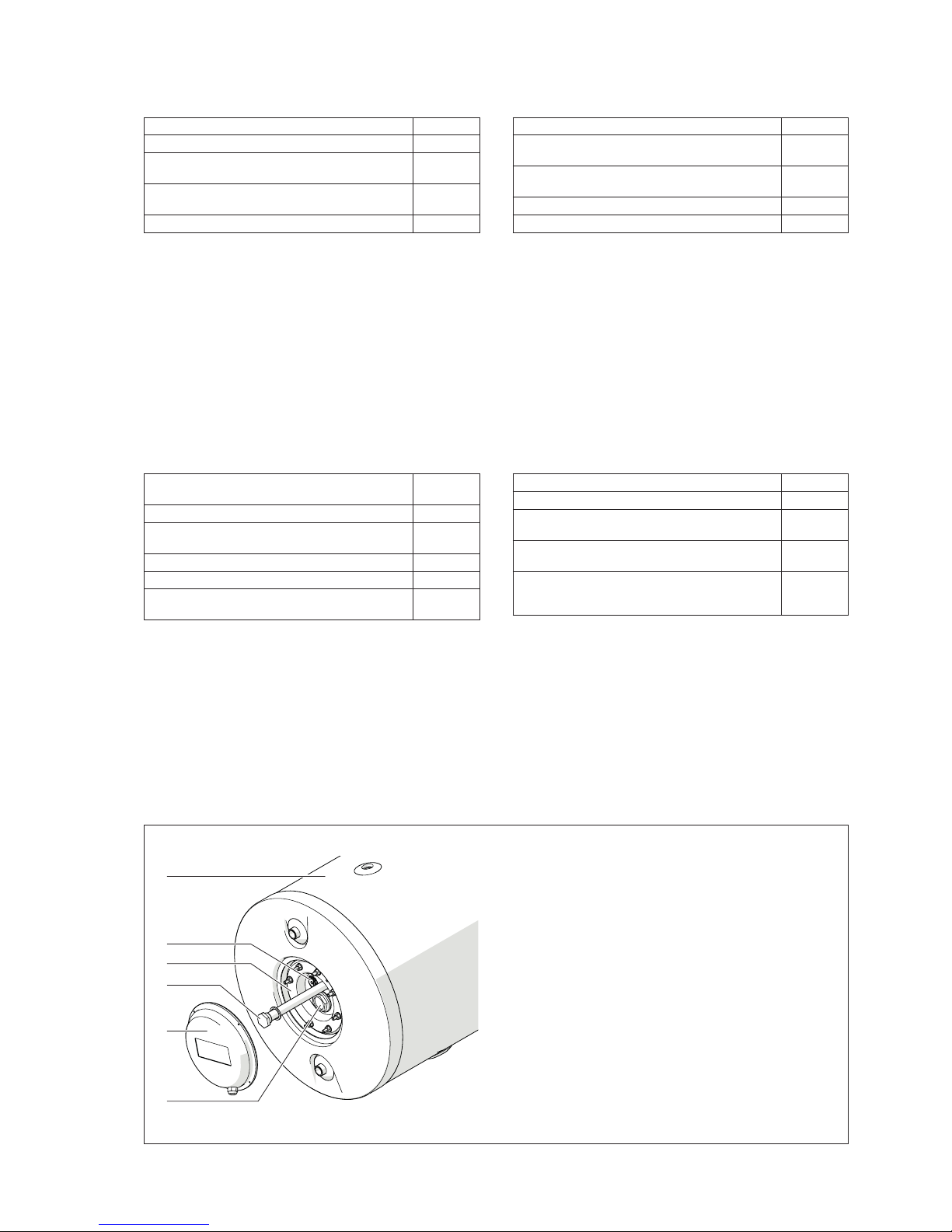
Storage cylinder components
1
2
3
4
5
6
1
Insulated storage cylinder
2
Sensor socket (1/2”)
3
Flange
4
Magnesium anode
5
Flange cover
6
Fitting for electrical heating element (accessory)
Technical Assistance Centre
Page 31
31
TECHNICAL ASSISTANCE CENTRE
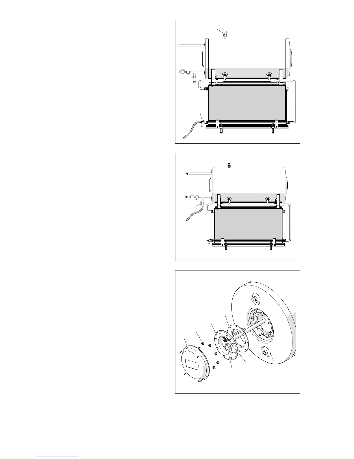
Topping up or changing the heat transfer liquid
For certain maintenance operations (such as replacing
pipes or unions or changing the heat transfer liquid) the
solar collector (primary) circuit may have to be drained.
Proceed as follows:
- Connect a hose to the hose union on the filling/drain
cock (1).
- Open the cock (1).
- Remove the safety valve (2) to allow air into the primary
circuit and allow the heat transfer liquid to flow out.
b
Only use the products listed in the S Catalogue
to top up the circuit.
b
In areas where there is a significant risk of freezing,
take particular care over tightness testing and flushing with water.
b
DO NOT drain the solar collector circuit under sunny conditions or when the collectors are hot.
Cleaning inside the storage cylinder
Proceed as follows to clean inside the storage cylinder:
- Close the domestic cold water inlet cock.
- Connect a hose to the storage cylinder drain cock (D)
fitted on installation, and open the cock. Leave the water run out until the tank is completely empty.
- Unscrew the fixing screws and remove the flange cover
(1) from the left of the storage cylinder.
- Remove the nuts (2) and screw the bolt (3) in to release
the flange (4) from the tank.
- Remove the flange (4). Check and clean the inside of
the tank.Check the condition of the seal (5). Replace if
necessary.
- Check the magnesium anode (6) for wear and replace
it if necessary.
- On completion of cleaning, follow the above steps in
the reverse order to refit all removed parts.
b
Screw the bolt (3) out until the flange fits snugly
against the tank. Tighten the nuts (2) to secure the
flange (4), proceeding diagonally around the flange
to apply pressure uniformly around the seal.
2
1
EAF
UAC
Sc
1
2
4
3
6
5
Page 32

32
END USER
END USER INSTRUCTIONS
The
SN TI
system is a solar hot water heating system that functions on the principle of natural circulation. The heat transfer
liquid therefore circulates by normal convection.
The system comprises one or more solar collectors and a jacket type storage cylinder, located above the collector/s.
The system does not require any pumps or adjustments.
18 PUTTING INTO SERVICE
The system must be put into service for the first time by S’s Technical Assistance Centre. After this it will continue to
function automatically.
19 MAINTENANCE
If the system is easily accessible, regularly check the cleanliness of the glass panel/s of the collector/s. If necessary,
clean the glass, but only when it is cold, preferably in the early morning. If access is difficult, contact your local Technical
Assistance Centre.
Once a year, check the condition of the insulation around the pipes.
If the system is not going to be used for an extended period of time, contact your local Technical Assistance Centre to
have it made safe.
b
The solar water heating system must be serviced periodically by S’s Technical Assistance Centre or by a qualified heating engineer.
b
The system must be serviced at least once a year.
b
If no domestic hot water is drawn off from the system, the safety valves of the domestic hot water and solar collector
circuits may open to discharge pressure and ensure correct functioning.
b
These safety valves present a risk of burns or scalding. If a pressure in excess of 2.5 bar builds up in the solar collector circuit, the safety valve opens.
b
Check the condition of the magnesium anode regularly as it provides protection against corrosion.
b
The system can reach very high temperatures (>150°C) under normal operating conditions. Take the greatest care
to avoid burns or scalding.
b
In the event of any malfunctioning or failure, and to have parts replaced, contact S’s Technical Assistance
Centre.
End user
Page 33

33
END USER
20 TROUBLESHOOTING
FAU LT CAUSE SOLUTION
No or insufficient domestic hot
water production
Unusually high draw of DHW. - Check.
Water leaks in the DHW distribution
circuit.
- Check.
Collector glass covered in dust or
leaves.
- Clean.
The level of heat transfer liquid in the
circuit has dropped as the result of
leaks from the unions or because of
over-temperature during extended
periods of disuse.
- Top up the circuit with water/glycol
mix and bleed any air out.
Air bubbles have formed inside the
circuit and are impeding natural
circulation.
- Bleed the circuit by loosening the
uppermost union on the short pipe
until liquid comes out.
- Top up to replace any lost liquid.
Vibrations Loose screws. - Tighten the screws.
21 DISPOSAL
When the system is no longer needed, do not abandon it in the environment, but dispose of it through appropriate channels and in compliance with applicable legislation.
Page 34

34
END USER
Page 35

35
END USER
Page 36

20100700 - Rev. 0 (06/15)
www.sylber.it
The manufacturer strives to continuously improve all products. Appearance, dimensions, technical specications,
standard equipment and accessories are therefore liable to modication without notice.
 Loading...