

Page 1
GB
Operating Instructions for the Software
Fingerprint Access System “FP530”
Item no. 1195621
Page 2

Table of Contents
Page
1. Introduction ...........................................................................................................................................................3
2. Short description of the FP530-PC software ...................................................................................................... 3
3. Explanation of Symbols ........................................................................................................................................3
4. Installation and Preparation ................................................................................................................................4
4.1 Software and Driver Installation .......................................................................................................................... 4
4.2 Preparation of the Hardware ................................................................................................................................5
5. First Steps ..............................................................................................................................................................6
6. Programming New Fingerprints ............................................................................................................................8
7. The Master Fingerprint ..........................................................................................................................................9
8. User Administration ..............................................................................................................................................9
9. Function Overview ............................................................................................................................................... 10
9.1 Expanded Software Functions „Options, File, Help, Exit“ (1, 2, 3, 4)................................................................. 11
9.2 Button „Relay“ (5) .................................................................................................................................................12
9.3 Fingerprints Saved on the PC / Fingerprints in the Sensor (6) ..........................................................................13
9.4 Functions for User Administration (7) .................................................................................................................14
9.5 Status Display (8) .................................................................................................................................................15
9.6 Minimise/Close Programme Window (9) .............................................................................................................15
9.7 Deactivate Logging (10) .......................................................................................................................................15
9.8 Button „Activate Switching Mode“ - Door Opener Mode (11) .............................................................................16
9.9 Fingerprint Display Window (12) ..........................................................................................................................16
9.10 Read/Save Image (13) ........................................................................................................................................... 17
10. Factory Reset ........................................................................................................................................................17
11. Frequently Asked Questions (FAQ) ..................................................................................................................... 18
GB
2
The home technology brand for the entire house. More information at www.sygonix.com
Page 3
1. Introduction
Dear Customer,
thank you for purchasing this product.
This product complies with the statutory national and European requirements.
To maintain this status and to ensure safe operation, you as the user must observe these operating instructions!
These operating instructions are part of this product. They contain important notes on commissioning and handling. Also
consider this if you pass on the product to any third parties.
Therefore, retain these operating instructions for reference!
All company names and product names are trademarks of their respective owners. All rights reserved.
If there are any technical questions, please contact:
International: www.conrad.com/contact
United Kingdom: www.conrad-electronic.co.uk/contact
2. Short description of the FP530-PC Software
The enclosed FP530-PC software provides many additional functions and facilitates the management of programmed users
(ngerprints).
Additionally, ngerprint les of the users can be copied from the sensor to the hard disc and archived. Thus, synchronisation
or distribution of the programmed ngerprints onto several FP530 units is possible.
Other functions:
• Programming or deleting individual ngerprints
• Assignment of names
• Assignment of the relays to the users
• Setting the relay switching time
• Direct switching function for the relays
• Recording of log les about access attempts
• Saving ngerprints as image les
• PIN query as access protection, can be activated
3. Explanation of Symbols
This symbol points out particular dangers associated with handling, function or operation.
The “arrow” symbol indicates special advice and operating information.
3
Page 4
4. Installation and Preparation
Before the ngerprint access system is connected to the PC, the software, including the driver, has to be installed and the
hardware prepared rst.
4.1 Software and Driver Installation
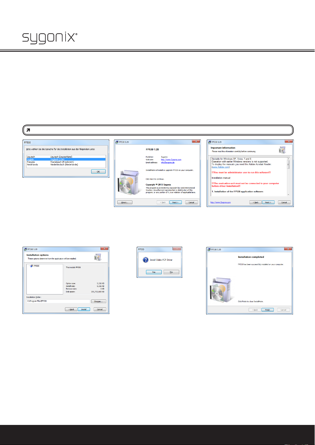
After inserting the enclosed CD into the corresponding drive of your computer, the installation will start automatically. If
autostart is deactivated on your PC, start the installation by double-clicking the programme “Setup.exe” in the main directory
of your CD.
When a safety prompt appears, conrm it by clicking “YES”. The desired installation language can be selected now.
The user must be logged in as administrator in Windows to perform this installation.
Step 1:
Selection of the language
(German, English, French,
Dutch)
Step 2:
Conrmation of the installa-
tion process via the button
"Continue"
Step 3:
Display of important information
for installation
Step 4:
Conrmation of the directory to install
the software in the suggested folder or to
manually select any other storage location
by clicking "Browser..." and then "Install".
The installation programme sets up a programme group "Sygonix FP530" in "PROGRAMMES" and a link to the desktop.
Step 5:
Conrm the installation of the required Silabs VCP driver with "Yes" if it is not present
yet. It must be installed under all circumstances. Then proceed according to the
instructions of the installation programme.
4
The home technology brand for the entire house. More information at www.sygonix.com
Step 6:
Installation of the FP530 software is com-
pleted. The device can now be connected
to the PC (observe chapter "4.2 Preparation
of the hardware"), switched on and the programme can be started via the entry in the
quick start bar or the icon on the desktop.
Page 5
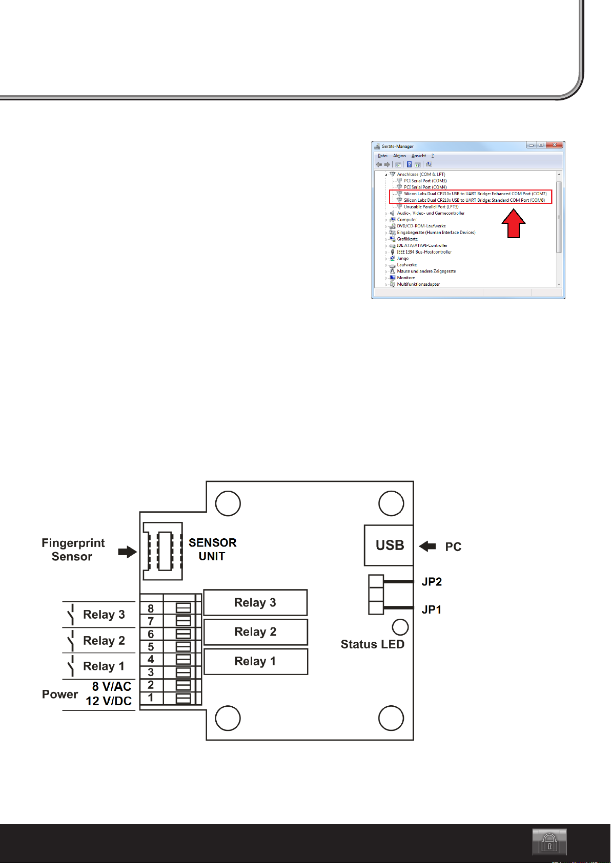
Inspection of the driver installation
To permit communication between the ngerprint module and the installed
software, the two COM ports used by the ngerprint module must be in the
range COM1 to COM8.
Therefore, reviewing the assigned COM ports in the windows device man-
ager is recommended.
If they are not in the range between COM1 and COM8, the ngerprint mod-
ule will not be recognised by the software!
Changing of the COM port is described in chapter “11. Frequently Asked
Questions (FAQ)”.
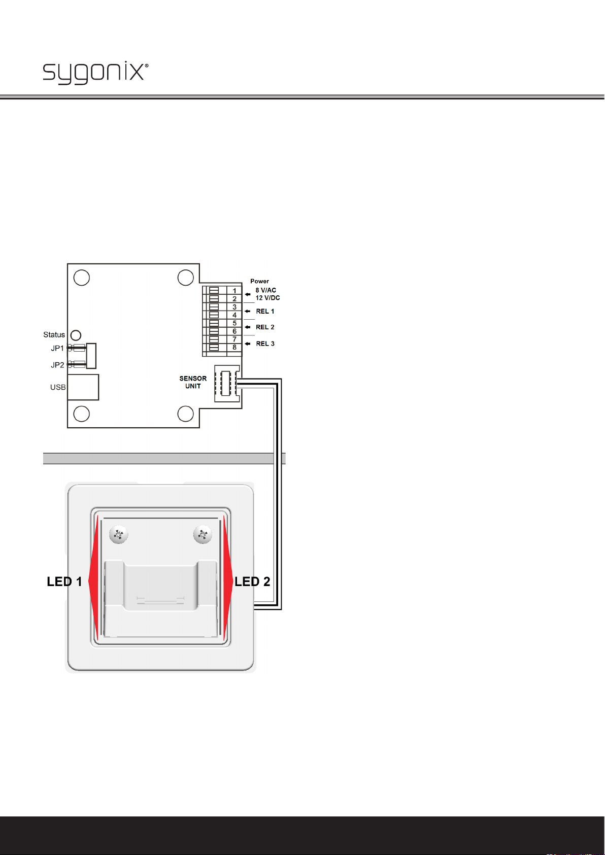
4.2 Preparation of the Hardware
To permit proper communication between the ngerprint module and PC software, no jumpers must be pushed onto the pin
strips “JP1” and “JP2”.
The ngerprint sensor must be connected to the evaluation unit via the enclosed cable at the connection “SENSOR UNIT”
(see gure below).
The ngerprint module is now connected to a free USB port of the computer via the mini USB socket on the evaluation unit
and a matching USB cable.
Then the operating voltage (12 V/DC or 8 V/AC) can be activated at the terminal clamps “POWER”. The polarity is irrelevant for
this.
Windows recognises the new hardware when it is connected for the rst time and completes the installation of the required
drivers.
5
Page 6
5. Getting Started
• Start the PC software via the Desktop icon or via “START / PROGRAMMES / Sygonix FP530”. The user must be logged in as
administrator.
• The PC software starts setting up the connection to the ngerprint module. This may take up to 30 seconds (observe
progress bar).
• After successfully starting the software and establishing the connection to the device, the ashing “status” display LED on
the evaluation unit of the ngerprint system signals proper function of the interface with the software. “LED1” and “LED2”
will remain lit at the ngerprint sensor.
Hardware overview / status-LEDs:
6
The home technology brand for the entire house. More information at www.sygonix.com
Page 7

• After the software has been started, the following programme window appears (the start window displayed here shows the
software in the delivery condition, i.e. no users are programmed yet).
• If ngerprints have already been programmed “without PC software” in the standalone mode, they are listed.
Observe that the ngerprints that were taught in in standalone mode are not fully compatible with the PC software, since
they are not assigned names or relays for system reasons.
If users are to be programmed via the PC software, the present users need to be deleted rst, since mixed operation with
differently programmed users is not admissible.
We generally recommend programming new ngerprints via the comfortable functions of the PC software.
Users programmed in standalone mode can, however, be recognised via the function identify, renamed and treated like
users programmed via the PC software by transfer to the PC and re-transfer to the sensor (relay assignments are then possible).
Starting window:
• Now the rst users can be taught in (see chapter “6. Programming New Fingerprints”).
7
Page 8

6. Programming New Fingerprints
The following items must be observed for correct recording of the ngerprint by the sensor:
• First place the nger in the housing to the depth stop as shown in the gure on the right.
• The nger must be pulled out of the housing towards the user across the sensor at a me-
dium speed (within approx. 1 second).
• The nger must be moved centrally, at and with slight pressure so that it will touch the
metal strips at the sensor throughout the scanning procedure. The nger must not stay on
the sensor during scanning!
• The software provides feedback as to whether the recording was successful or whether a
deviation resulted in the error (for instance, “nger moved too fast”).
• If programming is not continued for more than approx. 15 seconds, it is automatically cancelled.
The following items must be considered for best recognition of the nger prints:
• The same nger must be used for programming and verication at all times.
• The index nger is usually best for programming.
• Scarred ngers or callus make recognition more difcult. In this case, use a different nger.
• The sensor area should be cleaned with a soft, antistatic cloth if contaminated.
To programme new ngerprints with the PC software, the following steps must be performed:
Step 1:
Programming of new users is started by clicking the button “Add”. The rst user programmed via the PC software always is
the master ngerprint that is assigned special rights (see chapter “7. The Master Fingerprint”).
Step 2:
Now a prompt to enter the name of the ngerprint to be programmed and to conrm with “OK” appears. No invalid characters
must be entered, since the name cannot be conrmed otherwise.
Step 3:
Then the prompt appears to place the nger to be programmed and to pull it over the sensor. The user is then guided through
the programming process.
8
The home technology brand for the entire house. More information at www.sygonix.com
Page 9

Step 4:
The nger to be programmed must be placed in the housing to the depth stop so that it touches both metal strips at the
sensor for each reading process within 15 seconds.
Step 5:
Then the nger must be pulled out of the housing across the sensor as centrally as possible and at a medium speed (within
approx. 1 second).
Step 6:
This process must be performed several times, depending on the quality of the respective ngerprint recorded (typically 5x).
Always use the same nger for programming.
Step 7:
When the programming process is completed, the request window closes. The newly programmed ngerprint is listed in the
programme window “Fingerprints saved on the PC” and saved on the PC.
This successfully completes programming.
Observe that the ngerprint les of the newly taught-in ngerprints generally are saved on the hard disc of the PC and
are not on the ngerprint module yet. The users saved on the hard disc are listed in the programme window in the col-
umn “Fingerprints saved on the PC”. For more information on this, see the chapter “9.3 Fingerprints Saved on the PC /
Fingerprints in the Sensor”.
It is possible to programme the same nger several times, but it is not sensible and may lead to malfunction!
To warrant clear assignment, the same name must not be assigned to several users when programming. The programme does not differentiate between upper and lower case letters either, so that a present name will be overwritten
even if it differs from the name to be read by capitalisation. To maintain a good overview, it is recommended to number
the ngerprints of a person (e.g. Max-Finger1, Max-Finger2), if several ngers need to be programmed for one person.
7. The Master Fingerprint
The master ngerprint automatically is the user that was rst programmed into the system or the user that was dened as
master ngerprint in the PC software afterwards.
The “master authorisation” solely serves release of programming of new users if the device is not connected to a PC (stan-
dalone mode). This serves to protect against programming of undesired users. Within the PC software, the master ngerprint
does not have any special functions. In door opener mode, it behaves like the other users.
Deletion of the master ngerprint from the memory of the ngerprint sensor is solely possible by resetting of the “FP530”
system to the factory settings (see chapter “10. Factory Reset”). The function of the master ngerprint, however, can be trans-
ferred to any other user via the PC software.
8. User Administration
The PC software provides a number of additional functions to administrate the persons with access-rights. E.g. it enables
deleting individual users and assigning names. Normal users can also be designated as master ngerprint.
It is also possible to locally save taught-in ngerprint les of the device on the hard disc of the PC, no matter if the associated
users were programmed via PC software or in standalone mode. These ngerprint les permit transferring of users to other
PC systems. On demand, the locally saved ngerprint can then be copied into the memory of another ngerprint sensor with
the function “transfer”.
Detailed explanations on user administration are found in chapters “9.3 Fingerprints Saved on the PC / Fingerprints in the
Sensor”.
9
Page 10

9. Function Overview
Quick overview:
1 Programme window “Options” (switching times and names of the relay outputs, language, PIN, ...)
2 Opening image and log les
3 Help and information on Sygonix ngerprint
4 Exiting the PC software
5 Buttons for manual switching of the three relays
6 Display of archived ngerprints / users in the sensor
7 Functions for user administration
8 Status display for system messages
9 Minimise/close programme window
10 Activates/deactivates logging of data
11 Activates/deactivates switching mode (door opener mode)
12 Fingerprint display window
13 Reads in a ngerprint as a picture that can be saved.
In the following chapters, the functions listed above are explained in detail.
10
The home technology brand for the entire house. More information at www.sygonix.com
Page 11

9.1 Expanded Software Functions “Options, File, Help, Exit” (1, 2, 3, 4)
1. Options:
Selection of the programme language (German / English)
Designation of the outputs (three relays) and setting the associated switching times
in the range of 0.5 to 30 seconds
Language:
The programme language can be switched between German and English in the led “Language” in the “Options”,
Activate "PIN backup" and perform PIN
changes
Activate PIN protection, change PIN:
In order to protect the software from unauthorised access, an 8-digit PIN code is to be used. This can be activated via the
menu item “Options” in the led “PIN protection”. In the delivery condition, the PIN protection is deactivated. With the PIN
activated, a prompt will appear when starting the PC software. Then the user has full access to all software functions when
the PIN is entered correctly.
For reasons of safety, it is recommended to activate the PIN protection after the installation. For this, set the hook under “PIN
protection” in “Activated”. Then the user is asked to enter the desired PIN and conrm it again for safety. If a PIN is already
assigned and to be changed, the button “Change PIN” is available. Input of the old PIN is requested rst. Then the new PIN
can be entered, which must be conrmed again by being entered again.
The PIN must be eight characters long and may be made up of letters, numbers and special characters. When assigning a PIN,
capitalisation is important.
The PIN is saved in “FP530 module”. This means that it is also requested after reinstallation of the “FP530” user software,
if PIN query was activated originally.
The PIN access protection, only be revoked by factory reset, which will also lead to concurrent deletion of all users. Therefore,
it is particularly important to not forget the PIN used.
Output settings
The switching time of the three available relays can be set in the range from approx. 0.5 - 30 seconds. For this, the slider in
the eld “Output settings” in the menu item “Options” is used to set the desired time. Additionally, the relay output may be
named as desired.
After conrmation with “OK”, the setting is transferred to the device. This setting also applies for operation without a com-
puter.
User display
Indicates the user at the lower right in the Windows task bar who is currently switching relays, see gure
on the right.
11
Page 12

2. File
“Open folder image les”:
Opens the folder of the ngerprint image les saved via “Save image”.
“Open folder log les”:
The folder in which the “FP530” software saves the generated log les can be accessed via “File \ Open Folder Log les”. The
log les are saved and can be opened directly with a double-click.
Open last log:
The current log le can be displayed via “File \ Open last log”.
The Log File (Protocol Function)
In relay mode, all attempts at switching the relay by ngerprint are recorded in a log le along with date and time (as per
Windows system time). The le format is “.txt”.
The user associated with the access attempt is also saved if he is in the list of the programmed ngerprints. If a person who
does not have access rights tries to enter, this event is also saved (displayed as “User unknown”).
Example:
13.08.2013 ; 10:31:03 ; “User: Max Mustermann; relay 2 (Output 1)“
13.08.2013 ; 10:31:10 ; “Exiting switching mode.”
13.08.2013 ; 10:33:06 ; “User ‘Max’ has been declared Master.”
13.08.2013 ; 10:33:12 ; “Switch to switching mode.”
13.08.2013 ; 10:33:42 ; “The user is unknown.”
13.08.2013 ; 10:39:47 ; “Exiting switching mode.”
Every day, a new log le is set up with the respective date as le name (e.g. “01.03.2014.txt”).
3. Help/About
The help menu can be used to collect important information on the usage instructions stored. Clicking “Amount” will provide
information on the current software version.
4. Exit
Clicking “Exit” closes the software. At a restart, the ngerprint system needs approx. 10 seconds to be recognised by the PC software again.
9.2 Button “Relay” (5)
Clicking the button “Relay” of the desired exit will activate the relay according to the set time (menu “Options”). Thus, there
is the option to comfortably open the door from the PC.
Opening is displayed by the two light-emitting diodes at the sensor.
12
The home technology brand for the entire house. More information at www.sygonix.com
Page 13

9.3 Fingerprints Saved on the PC / Fingerprints in the Sensor (6)
Users who have been programmed via the function “Add” are saved on the hard disc of the PC as ngerprint le and displayed
in the column “Fingerprints saved on the PC”.
For the ngerprints to be applied, the respective les must be transferred to the ngerprint sensor (in the gure, the column
“Fingerprints in the sensor” already lists ngerprints that are in the ngerprint sensor’s memory).
To copy ngerprints onto the device, you can use the function “Transfer to the sensor” (users with identical names are overwritten after conrmation; however, a difference is made between upper and lower case).
After marking the desired ngerprint (multiple selection is possible when the Ctrl-button is kept pushed and the desired n-
gerprints are selected with the mouse) and then clicking the arrow “Transfer to the sensor”, the window for selection of the
outputs will appear (for multiple selection, the windows will appear in sequence).
Here, up to three relays can be activated at the same time and the settings can be conrmed with “OK”.
After successful transfer, the ngerprints are available in the column “Fingerprints in the sensor” on the device. When clicking
a user, the lower part of the window under “Assigned outputs” displays the relays this user switches.
If users are to be transferred from the device to the PC, the function “Transfer to PC” is available.
These functions can thus be used as backup functions, to synchronise or to distribute among several units (the ngerprints
can be copied to several ngerprint systems).
13
Page 14

9.4 Functions for User Administration (7)
Overview of the functions of user management:
Add:
Reads in a user and adds it to the list “Fingerprints stored on the PC” (see chapter “6. Programming New Fingerprints”).
Identify:
A user can use the function “Identify” to check if he is in the list of ngerprints in the sensor. After clicking the corresponding
button, the prompt appears to pull the nger over the sensor.
If the nger is recognised, the associated name appears above the ngerprint display window that displays the ngerprint
that has just been read as an image. Additionally, the name is displayed in the status display for system messages at the very
bottom of the programme window.
The function permits, e.g., identifying ngerprints without assigned names. These are, e.g., users who have been read in
without PC support. Therefore, reading in should preferably be done using the PC software.
Change Name:
The name of a ngerprint marked by clicking with the mouse can be changed in the list of the ngerprints saved on the PC
as well as the list of ngerprints in the sensor via the button “Rename” (multiple selection possible if the Strg.-button (or
Ctrl-button, depending on the country version of the keyboard) is kept pushed and the desired ngerprints are selected with
the mouse). In the dialogue window, inadmissible characters and the maximum character number are indicated - at multiple
selection, the windows appear in sequence. If an entry is changed to a name that is already listed, it is rejected. There is a
difference between upper and lower case.
Delete:
A user marked by clicking with the mouse can be removed from the list of the ngerprints saved on the PC as well as the list
of ngerprints in the sensor via the button “Delete” (multiple selection possible if the Strg.-button (or Ctrl-button, depending
on the country version of the keyboard) is kept pushed and the desired ngerprints are selected with the mouse).
Deleting of a ngerprint from the list “Fingerprints in the sensor” will release memory space on the sensor. If a ngerprint is
deleted in the column “ngerprints saved on the PC”, it is deleted from the hard disc of the PC. If the corresponding le in the
directory “C:\Users\Benutzername\AppData\Roaming\Sygonix FP530\Fingers” is not backed up (e.g. in another directory or
on the device itself), this ngerprint is deleted irrevocably.
The master ngerprint that is in the memory of the sensor cannot be deleted via the function “Delete”. To delete the master
ngerprint in the sensor, you must perform a reset to factory settings.
Declare master:
The function “Make master” can create a selected user as a new master ngerprint. This will replace the previous master
ngerprint and move to the rst slot of the list.
For this, the desired user is selected in the list “Fingerprints in the sensor” and declared the new master ngerprint by click-
ing the button “Make master”.
14
The home technology brand for the entire house. More information at www.sygonix.com
Page 15

9.5 Status Display (8)
The status display shows current system messages.
9.6 Minimise/Close Programme Window (9)
Click the button “Minimise” to minimise the programme window. The programme icon
is then displayed only in the menu bar (system tray). Double-click the programme icon in the
system tray (see gure on the right, Windows 7), the programme window can be maximised
again and displayed in full.
Click the button “Close” to close the PC software. At a restart, the ngerprint system
needs approx. 10 seconds to be recognised by the PC software again.
9.7 Deactivate Logging (10)
During switching operation, any attempt to switch the relay by ngerprint will be recorded in a log le together with date
and time (according to the Windows system time) – see “The log le (protocol function)” in chapter “9.1 Expanded software
functions…”
The green button “Deactivate logging” switches off recording of the switching attempts at the ngerprint module. The but-
ton then appears red. Clicking the now-red button “Activate logging” again will reactivate the recording and the button will
appear green.
Logging is active and can be deactivated by clicking the green button
Logging is inactive and can be activated by clicking the red button
15
Page 16

9.8 Button “Activate Switching Mode” - Door Opener Mode (11)
Clicking the button “Activate switching mode” will use the ngerprint system as a PC supported access control system. I.e.
when recognising an access-authorised ngerprint, the relay will switch according to the set time. Additionally, the time and
associated name are recorded in a log le if logging is activated (storage place of the log les: “C:\Users\Benutzername\
AppData\Roaming\Sygonix FP530\Log”).
Switching mode takes place by clicking the red button “Activate switching mode”. The button then appears green. If switching
is active, unneeded buttons are locked.
A click to the now-green button “Deactivate switching mode” terminates switching mode; the button then turns red again.
If a user is recognised, the name will appear above the ngerprint display window. The relay is activated according to the
reaction time set. Additionally, recognition is displayed by the LEDs at the sensor that ash during switching until the device
is ready for input again. If recognition is not successful, the two light-emitting diodes will ash thrice briey.
Switching mode is active and can be deactivated by clicking the green button
Switching mode is inactive and can be activated by clicking the red button
9.9 Fingerprint Display Window (12)
In the ngerprint display window, a picture of the ngerprint is displayed when reading a new user,
identifying and when “reading image”. This permits the user to track the quality and completeness of
the scan that has just been recorded.
16
The home technology brand for the entire house. More information at www.sygonix.com
Page 17

9.10 Read/Save Image (13)
The button “Read image” permits reading any nger and displaying a picture of the ngerprint. This picture can be saved as
a bitmap le (.bmp) via the button “Save image” in the path
C:\Users\Benutzername\AppData\Roaming\Sygonix FP530\Images
. Clicking “Read image” starts the reading process as usual. Then the picture of the ngerprint appears in the “ngerprint
display window”. After adding a new user and during identication, the image of the recorded ngerprint is displayed and
can be saved via “Save picture”.
“File” and “Open image les directory” permit directly calling the ngerprint picture le. The les saved are only picture les
and do not serve to recognise users or to execute functions.
Fingerprint data (ngerprints) are sensitive and strictly condential data!
Observe:
If the ngerprint of a user is to be saved as a .bmp picture le, his consent in writing must be collected rst! Disclosing
and passing it on to any third parties is only allowed with the user’s written consent. It must be ensured that all connected documents are protected against third parties accordingly.
10. Factory Reset
At a factory reset, all users, including the master ngerprint, are deleted and the switching time is reset to four seconds. The
PIN access protection for the PC software is revoked.
To reset the ngerprint system to the factory settings, the PC software has to be terminated and the connection to the PC
has to be disconnected.
Then proceed as follows:
• The included jumper is to be placed on the jumper slop “JP2” for approx. 30 second until the “LED1” at the sensor goes out
(“LED2” continues to be lit).
• The ngerprint system is now reset to the factory settings.
17
Page 18

11. FAQ (Frequently Asked Questions)
Why is the FP530 ngerprint system not recognised by the software?
• Observe that the two COM parts that were automatically assigned to the ngerprint system are in the range of COM1 to
COM8, see device manager:
“Connections (COM & LPT) / Silicon Labs Dual CP210x USB to UART...”
The ngerprint module will only work in this range of the COM ports. In the next section, it is explained how the COM port
of the driver can be changed.
• Is the “Silicon Labs” USB driver installed correctly? This can be reviewed in the device manager.
• Is the conguration of the jumpers correct? To establish connection with the PC and thus the software, both jumpers (JP1
and JP2) must be removed.
• Was a suitable USB cable used? (plug type A to plug type mini B)
How to change the driver COM port?
A change of the COM port is only required if one or both numbers of the COM port assigned by Windows are larger than 8.
The COM port can be changed in the device manager:
Open the device manager in the system control of the Windows system.
• Select the entry “Silicon Labs Dual CP210x USB to UART Bridge: Enhanced COM Port (COM..)” under “Connections (COM &
LPT)” and click it with the right mouse button.
• Under “Properties”, “Connection settings” and “Advanced”, the COM port can be changed in “COM connection number” (see
gure on the next page).
• Conrm these settings with “OK”.
Depending on the operating system version, the new setting will only be displayed after the device manager is restarted. The procedure may deviate slightly between different Windows systems.
18
The home technology brand for the entire house. More information at www.sygonix.com
Page 19

Due to leftovers from old driver installations, available COM ports may be displayed as “already assigned”. When assigning
such COM ports, verify their availability in every case. Otherwise, the communication of other hard and software may be
blocked.
Perform a restart if necessary.
Why does the status LED icker from time to time?
This is due to system reasons and thus normal.
Status Messages
“Requested slot not present - no memory free”
= Sensor storage fully assigned. No further user can be added.
“Time for process exceeded”
= Time exceeded when reading in a ngerprint. Reading of the ngerprint has been interrupted because no input was made
for more than 15 seconds.
“Time exceeded”
= Connection to the sensor has been lost. Check the wiring and the voltage supply to the ngerprint module. Then restart
the software.
19
Page 20

This is a publication by Conrad Electronic SE, Klaus-Conrad-Str. 1, D-92240 Hirschau (www.conrad.com).
All rights including translation reserved. Reproduction by any method, e.g. photocopy, microlming, or the capture in electronic data processing systems require the prior written approval by the editor. Reprinting, also in part, is prohibited. This publication represent the technical
status at the time of printing.
© Copyright 2016 by Conrad Electronic SE. 1195621_V2_1116_01_VTP_m_EN
Nr. 24457C
www.sygonix.com
 Loading...