

Short Instruction For Use EN
HF Inverter e@syDrive® 4638
EN
Distribution:
SycoTec GmbH & Co. KG
Wangener Strasse 78
88299 Leutkirch, Germany
Phone +49 7561 86-0
Fax +49 7561 86-371
info@sycotec.eu
www.sycotec.eu
Manufacturer:
SIEB & MEYER AG
Auf dem Schmaarkamp 21
21339 Lüneburg, Germany
Phone +49 (0)4131 203-0
Fax +49 (0)4131 203-2000
info@sieb-meyer.de
www.sieb-meyer.com
This short instruction for use includes only the essential control functions.
It does not however replace the Sieb & Meyer Hardware Description "Drive System
SD2S" that must be downloaded before commissiong:
- on the SycoTec homepage at the download area under
https://www.sycotec.eu/en/about-sycotec/downloads2/
respectively
- at Sieb & Meyer under
https://www.sieb-meyer.com/file-detail.html?item=421
The safety information have to be observed before commissioning!

EN
Content
1.0 Scope of Supply and Accessories 4
1.1 Scope of Supply 4
1.2 Accessories 4
2.0 Connections 4
3.0 Safety Circuit and Restart Lock 4
4.0 Motor 5
4.1 Motor Temperature Sensor 5
4.2 Assignment of the Parameter Sets 5
4.3 Connection choke 6
5.0 Power Supply 6
6.0 Digital and Analog Inputs / Outputs 6
6.1 Digital inputs 7
6.2 Digital Outputs 7
6.3 Analog Inputs 8
7.0 External Ballast Resistor 8
8.0 Example of remote control element 9
9.0 Connecting to the computer 9
10.0 Activate another parameter set 10
11.0 Load parameter file 10
12.0 Load Project 11
13.0 Status Display and Error Messages 12
Warranty Conditions 13
CE Declaration of Conformity 13
EN
4
1.0 Scope of Supply and Accessories
1.1 Scope of Supply
HF Inverter e@syDrive® 4638 Material no. 2.001.6091
(Drive System SD2S / device variant 0362121EC)
SycoTec – Short Instruction For Use Material no. 2.001.8020
HF Inverter e@syDrive® 4638
1.2 Accessories
Motor choke (220 µH, 12 A
eff
) Material no. 2.002.2384
Ballast resistor (400 W, 10 Ohm) Material no. 2.002.2385
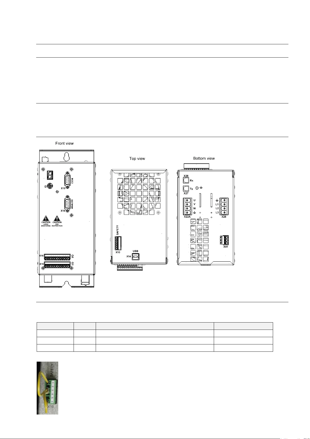
2.0 Connections
3.0 Safety Circuit and Restart Lock
The power supply unit is only activated when SAFEA and SAFEB are connected. If the safety function is not
required, pin1 and pin 3 must be bridged to pin 5.
Name
I/O
Meaning
Pin
SAFEA
I
Enable of safety circuit
X10/1
SAFEB
I
Enable of safety circuit
X10/3
24 V
O
Logic voltage 18 – 28 V
X10/6
The 24V output is not suited to supply external safety circuits.
EN
5
4.0 Motor
Name
I/O
Meaning
Pin
U O Motor phase U
X22A/U
V O Motor phase V
X22A/V
W O Motor phase W
X22A/W
PE Protective conductor
X22A/PE
4.1 Motor Temperature Sensor
Name
I/O
Meaning
Pin
Temp
I
Motor temperature sensor (towards GND)
X16/9
GND
I/O
Ground
X16/11,12
4.2 Assignment of the Parameter Sets
Assignment
Parameter set of motor spindle
Remark
P00
4060 E
P01
4060 ER
P02
4060 ER-S
P03
4060/4061 AC
P04
4060 AC-T
P05
50100 AC-duo
P06
4060/4061 DC-S_SVC
Motor spindle must be operated with an
upstream choke / external inductance of
220 µH
P07
4060/4061 DC-T_SVC
P08
4064 DC SK_SVC
P09
4064 DC HSK_SVC
P10
5045 DC-HV 60.P4_SVC
P15
4060/4061 DC-S_HSPWM
Alternative function types, without choke
P16
4060/4061 DC-T_HSPWM
P17
4064 DC_HSPWM
EN
6
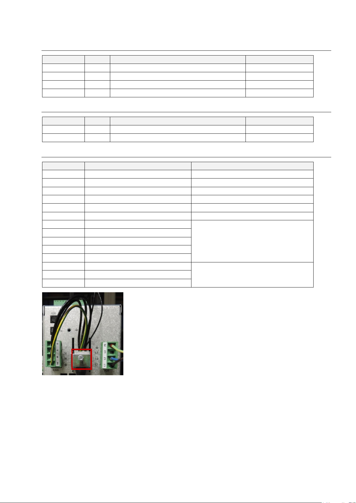
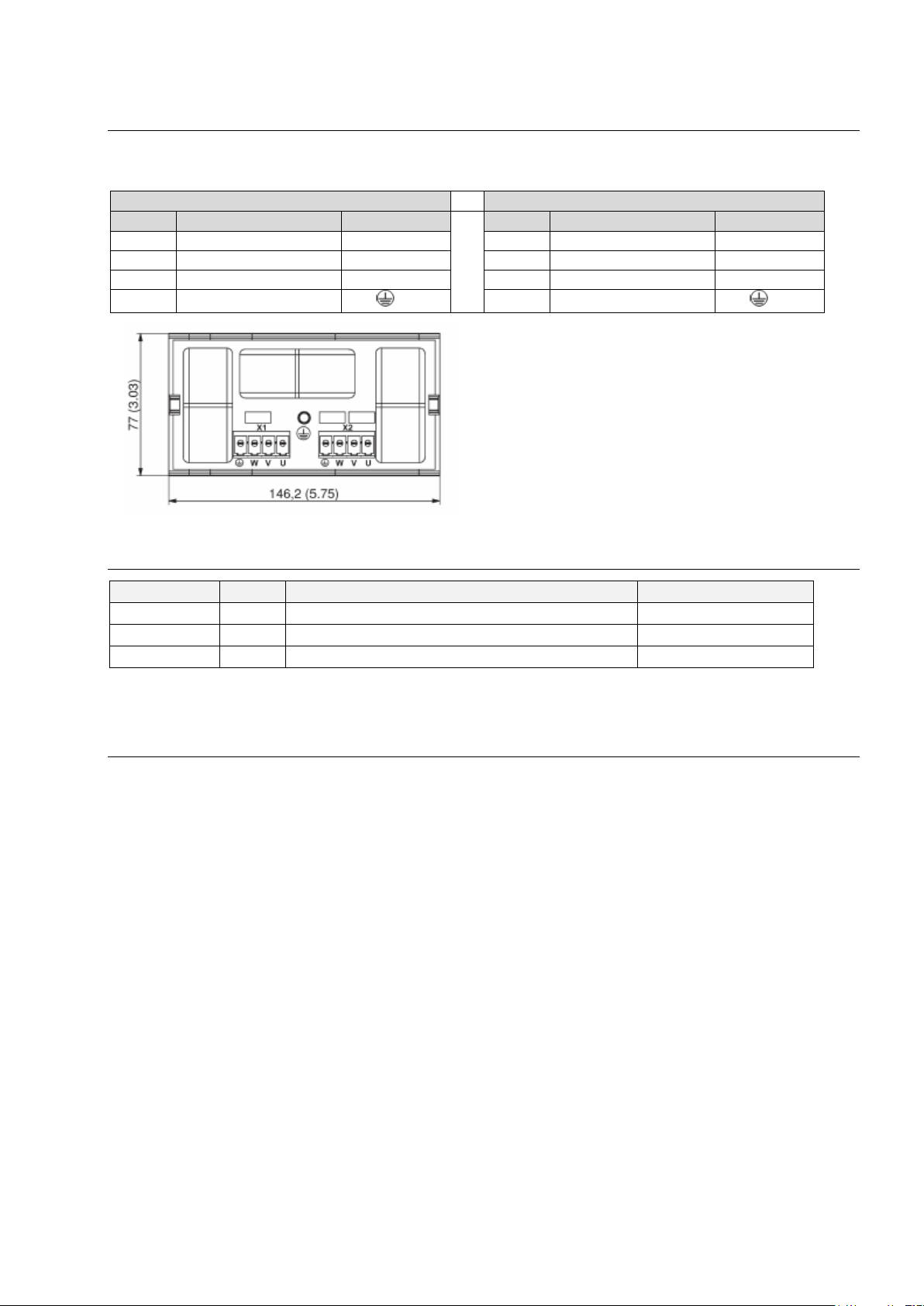
4.3 Connection choke
The connection X22A (Motor) of the frequency inverter is connected to connection X1 (Drive) of the choke.
The motor phases are connected to X2 (Motor) of the choke.
X1 (Drive)
X2 (Motor)
Name
Meaning
Pin (Choke)
Name
Meaning
Pin (Choke)
U
Motor phase U
X1/U
U
Motor phase U
X2/U
V
Motor phase V
X1/V
V
Motor phase V
X2/V
W
Motor phase W
X1/W
W
Motor phase W
X2/W
PE
Protective conductor
X1/
PE
Protective conductor
X2/
5.0 Power Supply
Name
I/O
Meaning
Pin
L1 I Main supply
X28/L1
L2 I Main supply
X28/L2
PE Protective conductor
X28/PE
Voltage range: 150 V AC -10% to 230 V AC +10%
6.0 Digital and Analog Inputs / Outputs
If you want to make use of the digital inputs and outputs, connect pin x15/9 to 24 V.
The functions / assignments of the inputs and outputs can be configured via the "drivemaster2" software.
By default, the following functions / assignments are set.
EN
7
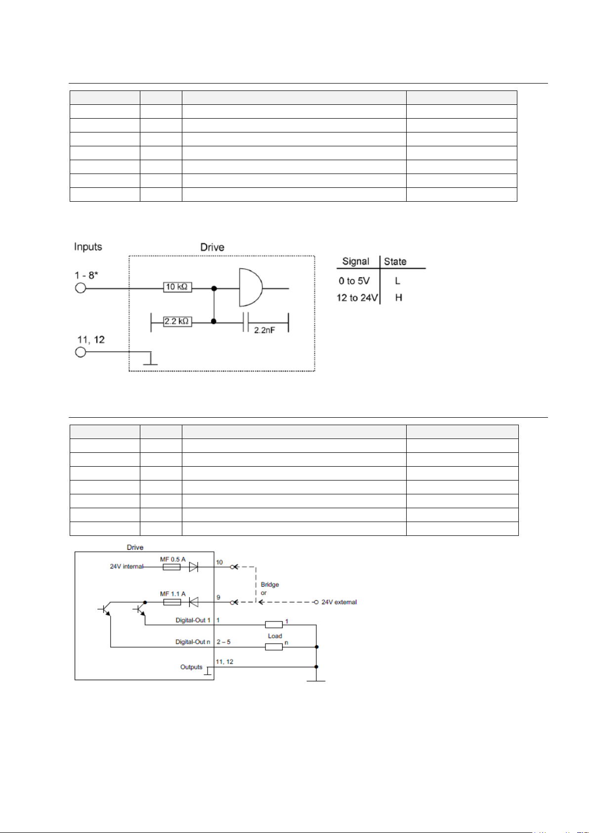
6.1 Digital Inputs
Name
I/O
Function / Assignment
Pin
IN0 I Switch on
X16/1
IN1 I Operation enable
X16/2
IN2 I Error reset
X16/3
IN6 I Speed direction
X16/7
GND
I/O
Ground
X16/11,12
VCC-IO
I
24 V supply for IO
X15/9
VCC-OUT
O
24 V output for IO (max. 0,3 A)
X15/10
IN0 "Switch on" activates the controller, the holding current is applied to the motor spindle.
If the controller is active, the motor spindle can be started with IN1 "Operation enable".
[*] Yet another digital input is located at the connector X15, pin 6.
6.2 Digital Outputs
Name
I/O
Function/Assignment
Pin
OUT0
O
Ready type 1
X15/1
OUT1
O
M02 - Message operation enabled
X15/2
OUT2
O
M12 - Speed zero
X15/3
OUT3
O
M10 - Ref. value reached
X15/4
VCC-IO
I
24 V supply for IO
X15/9
VCC-OUT
O
24 V output for IO (max. 0,3 A)
X15/10
GND
I/O
Ground
X15/11,12
Every output can be loaded with 100 mA.

EN
8
6.3 Analog Inputs
Name
I/O
Function/Assignment
Pin
AIN0+
I
Speed reference value
X18/3
GND
I/O
Ground
X18/4
AIN0-
I
Reference point for AIN0+ (bridge with ground)
X18/7
VCC_10
O
10 V supply voltage
X18/9
Voltage interface with input voltage range: ± 10 V
Can also be connected to potentiometer (500 Ohm – 5 kOhm
7.0 External Ballast Resistor
Name
Function / Assignment
Pin
Rextern
External ballast resistor
X41/1
Rintern
Internal ballast resistor
X41/2
UB+
X41/3
If no external ballast resistor is used, pin 1 and pin 2 of connector X41 must be bridged.
The technical data of the optionally connected external ballast resistor must be entered via the
"drivemaster2" software.
By default no external ballast resistor is set.

EN
9
8.0 Example of remote control element
9.0 Connecting to the computer
➢ Connect the inverter via USB interface to the computer
➢ Plug in the inverter
➢ Start Sieb & Meyer "SD2 Windows software drivemaster2"
https://www.sieb-meyer.com/file-detail.html?item=413
To establish a connection to the device click "Setup connection to the device", adjust "USB" for connection
type and select "Search devices + connect".

EN
10
10.0 Activate another parameter set
To activate a different parameter file, enter the number (P00 … Pxx) of the required parameter file and click
"Apply".
11.0 Load parameter file
Before opening the parameter file select the right position (Pxx) or add a new parameter set.
EN
11
To open a parameter file click "Open parameters" on the toolbar and select the required parameter file.
To write the parameter file into the inverter click "Write parameters to drive" on the toolbar.
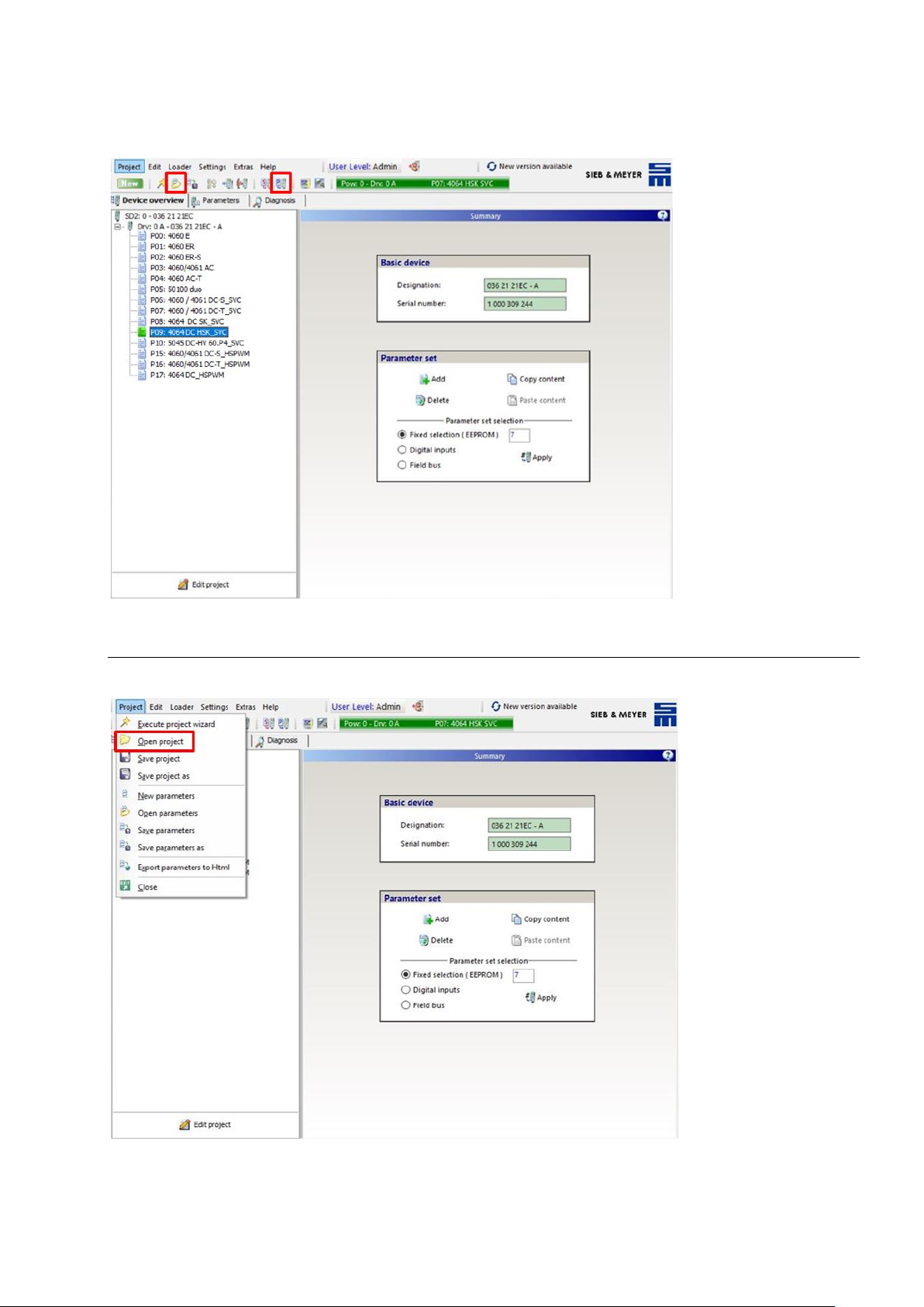
12.0 Load Project
To open a project select "Project" and then "Open project". Select the required project file and click "Open".

EN
12
To write the project to the inverter select "Loader" in the menu bar and then "Write project to drive".
13.0 Status Display and Error Messages
The 7-segment display shows status and error messages.
All messages end with dot behind the last digit. When the first digit is "E.", there is a permanent error.
Examples:
1.
Startup Message
- Controller is in boot loader mode: Display appears short-time when
the device is booted and when the system software is loaded.
2.
Ready To Switch On
- Controller is switched off
- No error
3.
Controller Active
- Controller is switched on
- No error
4.
Error Message
- Controller is switched off due to error E40
The error is not present anymore
5.
Persistent Error Message
- Controller is switched off due to error E40
- The error is still present

EN
13
Warranty Conditions
Under current SycoTec delivery and payment conditions, SycoTec undertakes warranty for satisfactory
function and freedom from faults in material and manufacture for a period of 12 months from the date of
sale certified by the vendor.
In the event of justifiable complaints, SycoTec shall supply spare parts or carry out repairs free of charge
under warranty. SycoTec accepts no liability for defects and their consequences which have arisen or could
have arisen as a result of natural wear and tear, improper handling, cleaning or maintenance, noncompliance with the maintenance, operating or connecting instructions, corrosion, impurities in the air
supply or chemical or electrical influences which are unusual or not admissible in accordance with
SycoTec's standards. The warranty claims shall become null and void if defects or their consequences can
be attributed to interventions in or modifications to the product. Warranty claims can only be validated if they
are notified immediately in writing to SycoTec.
A copy invoice or delivery note clearly showing the manufacture number shall be attached if products are
returned.
CE Declaration of Conformity
The CE Declaration of conformity may be requested or downloaded from www.sycotec.eu.

2.001.8020 / 201
9-06
(DE = original)
 Loading...