

SYCLOPE TRACE’O® : Universal controller for trace detection (Part 1)
Installation and starting instructions
Reference : CTR 0001 Rev : 2

General information Page 2/40
►
Parts of the general documentation
1 : Installation and starting instructions
Part
2 : Programming instructions
Part
3 : Communications instructions
Part
General information :
®
SYCLOPE Electronique 2016
Manual of 2016, February 18th Rev 2
Universal controller for standard and trace measurement.
Product line TRACE’O
®
Part 1 : Installation and starting instructions (Ref. DOC0321)
Editor :
SYCLOPE Electronique S.A.S.
Z.I. Aéropole pyrénées
Rue du Bruscos
64 230 SAUVAGNON - France
Tel : (33) 05 59 33 70 36
Fax : (33) 05 59 33 70 37
Email : syclope@syclope.fr
Internet : http://www.syclope.fr
© 2015 - 2016 by SYCLOPE Electronique S.A.S.
Subject to modifications
Installation and starting instruction manual SYCLOPE TRACE’O
®

Summary Page 3/40
Summary
General informations ......................................................................................................... 4
I.
1) Applicability ...................................................................................................................... 4
2) Use of the document ......................................................................................................... 5
3) Symbols and signs ............................................................................................................. 5
4) Storage and transport ........................................................................................................ 6
5) Packaging ......................................................................................................................... 6
6) Warranty .......................................................................................................................... 6
II. environment and safety procedures .................................................................................... 7
1) Use of the equipment ........................................................................................................ 7
2) User obligations ................................................................................................................ 7
3) Risk prevention ................................................................................................................. 7
4) Identification and localization of the identification plate ....................................................... 8
5) Disposal and conformity ..................................................................................................... 9
III. Technical specifications and functions ................................................................................10
1) Features ..........................................................................................................................10
2) Main functions ..................................................................................................................11
3) Measurement parameters, scales and control ranges ..........................................................12
a) Basic versions : Direct entries (2x 4…20mA) or isolated entries (2x 4…20mA) ......................12
b) Version with 1 isolated potentiometric entry and 1 isolated 4-20mA entry ............................13
c) Version with 2 potentiometric entries .................................................................................14
IV. Installation and wiring ......................................................................................................15
1) Installation conditions .......................................................................................................15
2) Installation of the wall-mounted controllers........................................................................15
3) Electrical connections .......................................................................................................15
4) Connection of the primary power supply ............................................................................16
5) Connexion of the free of potential relays (KA, KB, KC et KD) ...............................................17
6) Connection of the measurement inputs ..............................................................................17
7) Connections of the analogue outputs (IA1 and IA2 .............................................................20
8) Connection of the remote control input (CAD) ....................................................................20
9) Connection of the flow control entry sensor (Flsw) or low level detection tank .....................21
10) Connection of the counter entry (Flow) or low level detection tank ......................................22
11) Connection of the RS232C printer output ...........................................................................22
12) Branchements du bus de communication RS485 .................................................................22
13) Connections of the MODEM port for communications ..........................................................23
14) Connection of GMS, Wifi and Ethernet modems for internet access .....................................24
15) Connection of the internal socket modem ..........................................................................24
V. Expendable external connection box ..................................................................................25
VI. General uses ....................................................................................................................26
1) Using « standard » mode ..................................................................................................26
2) Using « trace » mode .......................................................................................................27
VII. Introduction to the human-machine interface (HMI) ...........................................................28
1) Display and control keypad ...............................................................................................28
2) Internal connections .........................................................................................................29
3) Terminal block connections ...............................................................................................29
VIII. Commissioning .................................................................................................................30
1) Choosing the language .....................................................................................................30
2) Setting real-time clock ......................................................................................................31
3) Contrast adjust (Only when « Stopped ») ..........................................................................31
4) Setting display screens .....................................................................................................31
5) Programming setpoints .....................................................................................................33
6) Programming technical alarms ..........................................................................................34
7) Calibration of measurement probes ...................................................................................34
8) Start processes and dosages .............................................................................................35
IX. Guide and maintenance. ...................................................................................................37
Installation and starting instruction manual SYCLOPE TRACE’O
®

General informations Page 4/40
I. General informations
1) Applicability
SYCLOPE TRACE’O® controller range you have just purchased is an electronic special equipment for
measuring standard chemistry in trace range. It has been carefully developed and manufactured to
ensure your greatest pleasure and peace of action.
Its remarkable capacity of adaptation to the different situations means it can be installed in the most
difficult environments where processes and measurements of water are decisive.
®
Designed according to the needs of the customer, the SYCLOPE TRACE’O
controller is equipped with
four analog inputs for specific sensors for treating water and also include alarm functions and
regulations with cyclic commands transmitted by means of 4 configurable relays to control pH chemistry
levels of the water.
®
When using chlorine or ozone measurement, SYCLOPE TRACE’O
controller is able to measure
automatically some traces of chemistry with a special processing for guarantying the good working of
the respective sensors.
Two ports, RS232 and RS485, for a printer and/or a computer link, allows communication by direct link
or modem to a desktop computer (PC) for filing and graphic processing of the acquisition data.
®
The SYSCOM
software application has been developed to perform these functions.
®
TRACOM
software also developed by SYCLOPE Electronique S.A.S. makes it possible to ensure the
maintenance and the programming of the basic functions as well as the functions necessary to the
communications with the Internet.
®
With an adequate interface carrying out internet connectivity, SYCLOPE TRACE’O
will be connected
in real-time to Internet site “mysyclope.com” thus ensuring a management and a total follow-up of
all the parameters as well as a management of alarms by email or SMS in all circumstances. (Yearly
subscription of access to be envisaged)
®
The simplicity of operation of the SYCLOPE TRACE’O
, the user friendliness and the remarkable
technical aspects of these controllers, will ensure you benefit from their many options, guaranteeing
you full control and supervision of the quality of the water.
The following instructions contain all the information required for the installation, use and maintenance
of your new equipment.
Installation
Technical specifications
Commissioning instructions
Safety tips
If you would like to receive further information or if you encounter any difficulties not described in this
manual, please contact your usual retailer or else directly contact the sales department of SYCLOPE
Electronique S.A.S., either at the agency or at the office for your region, or the technical/quality
departments of our establishments. We will do everything in our power to help you and ensure you
benefit from our advice and know-how in the field of measurement and treatment of swimming-pool
water.
Contact : service-technique@syclope.fr
Installation and starting instruction manual SYCLOPE TRACE’O
®
General informations Page 5/40
2) Use of the document
Please read this entire document before starting to install, adjust or commission your controller device,
in order to ensure the safety of swimmers, users and equipment.
The information provided in this document must be strictly observed. SYCLOPE Electronique S.A.S.
declines all responsibility in cases where failure to comply with the instructions of this documents is
observed.
The following symbols and pictograms will be used to facilitate reading and understanding of these
instructions.
● Information
► Action to be taken
Item of a list or catalogue
3) Symbols and signs
Identification of a continue voltage or current
Identification of an alternative voltage or current
Protective ground
Functional ground
Risk of injury or accident. Identify a warning concerning a potentially dangerous risk.
Documentation must be consulted by the user with each time the symbol is notified. If the
instructions are not respected, that presents a risk of death, physical injuries or property
damages.
Electric hazard. Identify a warning statement relative to a mortal electric danger. If the
instructions are not strictly respected, that implies an inevitable risk of physical injuries or
death.
Risk of incorrect operation or damage for the device.
Comment or particular information.
Recyclable element
Installation and starting instruction manual SYCLOPE TRACE’O
®
General informations Page 6/40
4) Storage and transport
It is important to store and transport your SYCLOPE TRACE’O® in its original packaging in
order to minimize risk of damage.
Furthermore, the package must be stored in an environment that is protected against
humidity and exposure to chemical products.
Environmental conditions for transport and storage:
Temperature: -10 °C to 70 °C
Air humidity: Maximum of 90% with no condensation
5) Packaging
The controller is delivered without electrical power cable.
The pre-holes of the box are drilled and equipped with according electrical glands in
compliance with IP65 level protection. Cables must be adapted to the electrical glands to
respect the level of protection.
Grounded cables for connecting pH and ORP (Redox) sensors are not provided.
Content of the packaging :
®
One analyzer/controller SYCLOPE TRACE’O
Installation and starting instruction notice
Programming notice
Communication notice (Option)
6) Warranty
The warranty is provided according to the terms of our general conditions of sale and delivery as long
as the following conditions are met:
Use of the equipment according to the instructions of this notice
No modifications of the equipment which may modify its behavior and no incorrect
manipulation
Respect for the electrical safety conditions
Consumable material is no longer covered by the warranty when in use.
Installation and starting instruction manual SYCLOPE TRACE’O
®
Environment and safety procedures Page 7/40
II. environment and safety procedures
Please:
Read this manual carefully before unpacking, installing or commissioning this equipment
Take into account all the hazards and recommended precautionary measures
Failure to respect these procedures can result in serious injury to users or damage the device.
1) Use of the equipment
The SYCLOPE TRACE’O® system has been designed to measure and control physico-chemical
parameters by means of sensors and controls of suitable actuators in the context of the possible uses
described in this manual.
All other uses are considered to be non-conforming and must therefore be forbidden.
SYCLOPE Electronique S.A.S. will not be responsible in any case for any damages that result
from such uses.
Any use of sensors or interfaces not-in conformity to the features defined in this handbook
must also be proscribed.
2) User obligations
The user undertakes not to allow its employees to work with the SYCLOPE TRACE’O® equipment
described in this manual unless they:
Are aware of the fundamental instructions relating to work safety and prevention of accidents
Are trained in the use of the device and its environment
Have read and understood these instructions, warnings and manipulation rules
3) Risk prevention
The installation and connection of the SYCLOPE TRACE’O® equipment should only be
performed by personnel specialized and qualified for this task.
The installation must comply with current safety standards and instructions!
Before switching the controller on or manipulating the relay outputs, remember always to
cut off the primary power supply!
Never open the controller when it is powered on!
Maintenance operations and repairs should only be performed by trained, specialized
personnel!
Take care when choosing the location for installing the equipment according to the
environment!
®
The SYCLOPE TRACE’O
electronic box should not be installed in a hazardous
environment and should be protected against splashing with water or chemical products. It
should be installed in a dry, well-ventilated location, isolated from corrosive vapours.
Installation and starting instruction manual SYCLOPE TRACE’O
®
Environment and safety procedures Page 8/40
8
9
11
12
13
14
15
1
2
3 4 5
6 7 1
2 3 4 5 6
8
11
12
7
14
13
10
15
TRACE’O
Ref: CTR 0001
90 - 240VAC 50/60Hz
www.syclope.fr Made in France
0,3 - 0,16A
IP65
S/N: 13044217
Make sure that the chemical sensors used with this device correspond well to the chemicals
used. Refer to the individual technical note of each sensor. Chemistry of water is very
complex, in case of doubt, contact immediately our engineering service or your approved
installer/reseller.
Chemical sensors are sensitive elements using consumable parts. They must be supervised,
maintained and calibrated regularly using specific calibrator systems not-provided with this
equipment. In the event of defect, a surplus possible hazard of chemical injections can be
noted. In the doubt, a service contract must be taken near your reseller/installer or failing
this near our engineering services.
Contact your approved installer/reseller or our business
service for more information.
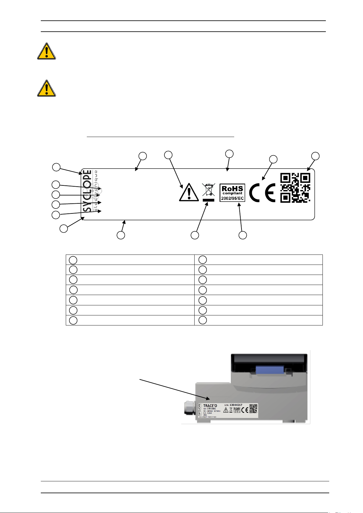
4) Identification and localization of the identification plate
Label of the manufacturer Serial number
Model of the product Particular risks Read de manual
Reference of the product Product which can be recycled
Range of the power supply Limitation of dangerous substances
Values of the maimum current EC compliance
Class of the protection Country of the manufacturer
Identification of the manufacturer Manufacturer Square code
Identification plate
Installation and starting instruction manual SYCLOPE TRACE’O
®
Environment and safety procedures Page 9/40
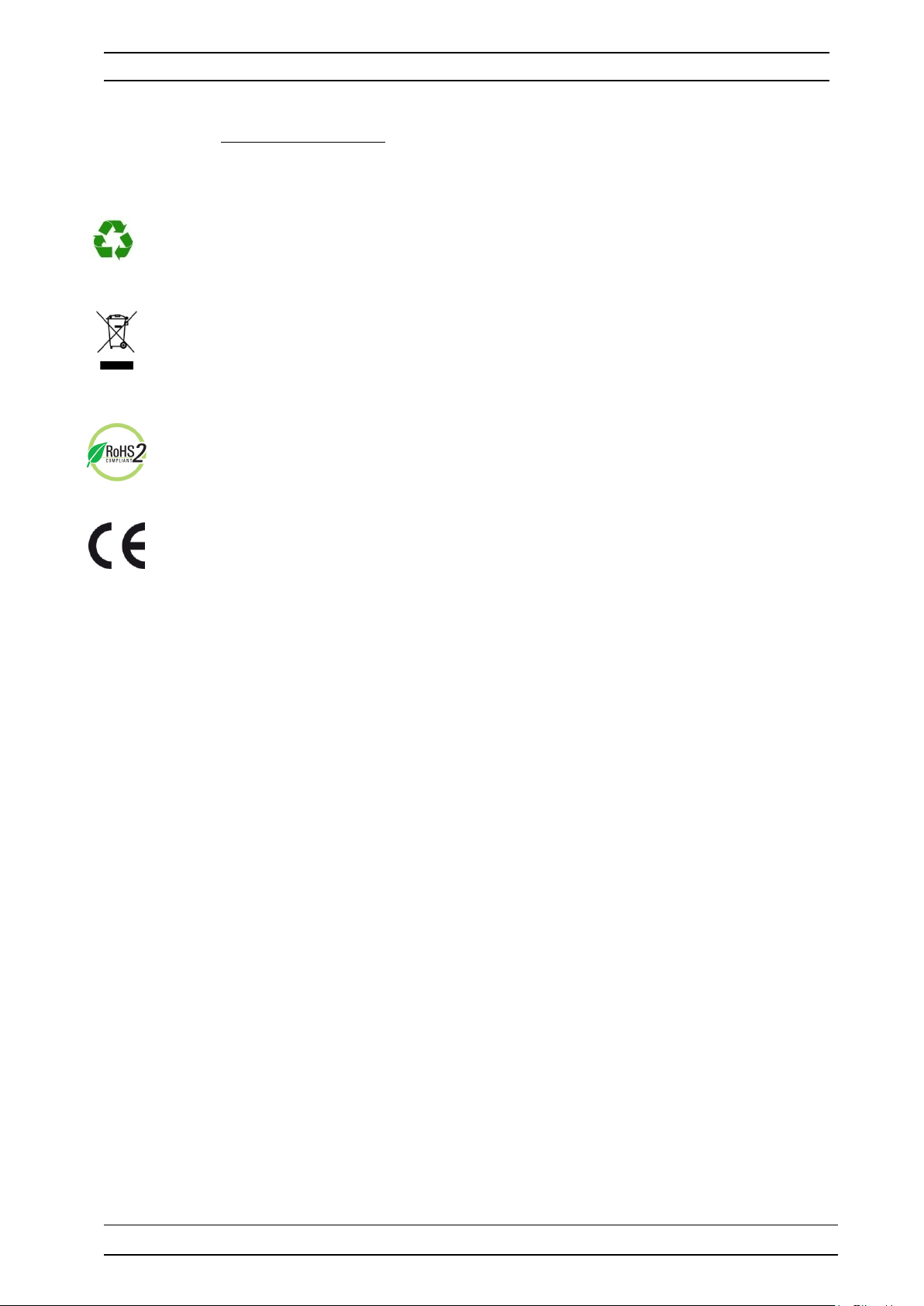
5) Disposal and conformity
The recyclable packaging of the SYCLOPE TRACE’O® equipment must be disposed of according to
current regulations.
Elements such as paper, cardboard, plastic or any other recyclable elements must be taken
to a suitable sorting center.
According to European directive 2012/19/UE, this symbol means that as of 2012, July 4
th
electrical appliances cannot be thrown out together with household or industrial waste.
According to current regulations, consumers within the European Union are required, as of
this date, to return their used devices to the manufacturer, who will take care of disposing
them at no extra expense.
According to European directive 2011/65/UE, this symbol means that the SYCLOPE
®
TRACE’O
controller is designed in compliance with the restrictions on hazardous
substances
According to low-voltage directive (2014/35/UE), the electromagnetic compatibility directive
(2014/30/UE) and the RoHs2 directive (2011/65/UE) this symbol means that the device has
been designed in compliance with the previously cited directives
,
Installation and starting instruction manual SYCLOPE TRACE’O
®
Technical characteristics Page 10/40
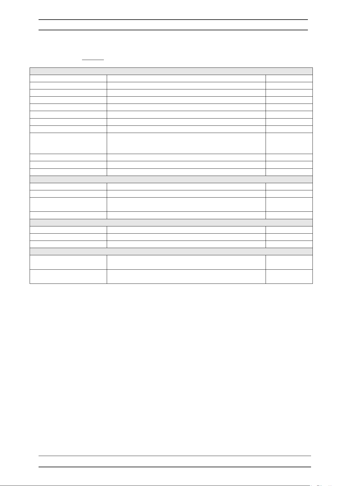
General characteristics
Type
Specification (s)
Marker(s)
Consumption
0,3 to 0,15A Maxi. (Without external load)
-
Power supply required
Between 90VAC and 240VAC +/-10%
-
Electric protection
Fuse 315 mA Time-lag 5x20 glass
F1
Operating Temp. (°C)
-5 °C to 45 °C
-
Storage temperature (°C)
-10 °C to 70 °C
-
Humidity
Max. 90% without condensation
-
Case material
ABS or Polycarbonate (US et Canada)
-
Length : 185 mm (7,3 inches)
Height : 119 mm (4,7 inches)
-
Weight of the case
1,2 kg
-
Protection rating
IP 65 - Display
Blue back-light 128x64 LCD screen
-
Inputs
Measurement inputs
2x 4…20mA inputs on special configuration modules
Auxiliary input
1x 4…20mA auxiliary input for additional function (Option)
1x control input for external Start/Stop
1x control input for level tank or flow-level input
CAD
Flsw
Metering input
1x flow meter pulse input or chemical product level tank
Flow
Outputs
Relay outputs
4x Free of potential relays Max. 5A 250VAC
KA;KB;KC;KD
Analog outputs
2x Analog outputs 0/4…20 mA Max 500 Ω
IA ; IB
Printer output
1x RS232 for serial printer
SV3
Communications
1x Communication port RS485 type for compatible software
protocol type “MODBUS RTU”
RS485
1x RJ-45 connector for phone line socket modem or GSM,
WIFI or Ethernet internal modem.
Modem line
III. Technical specifications and functions
1) Features
Case dimensions
Control inputs
RS485 Bus
Modem (Optional)
Width : 185 mm (7,3 inches)
Installation and starting instruction manual SYCLOPE TRACE’O
®
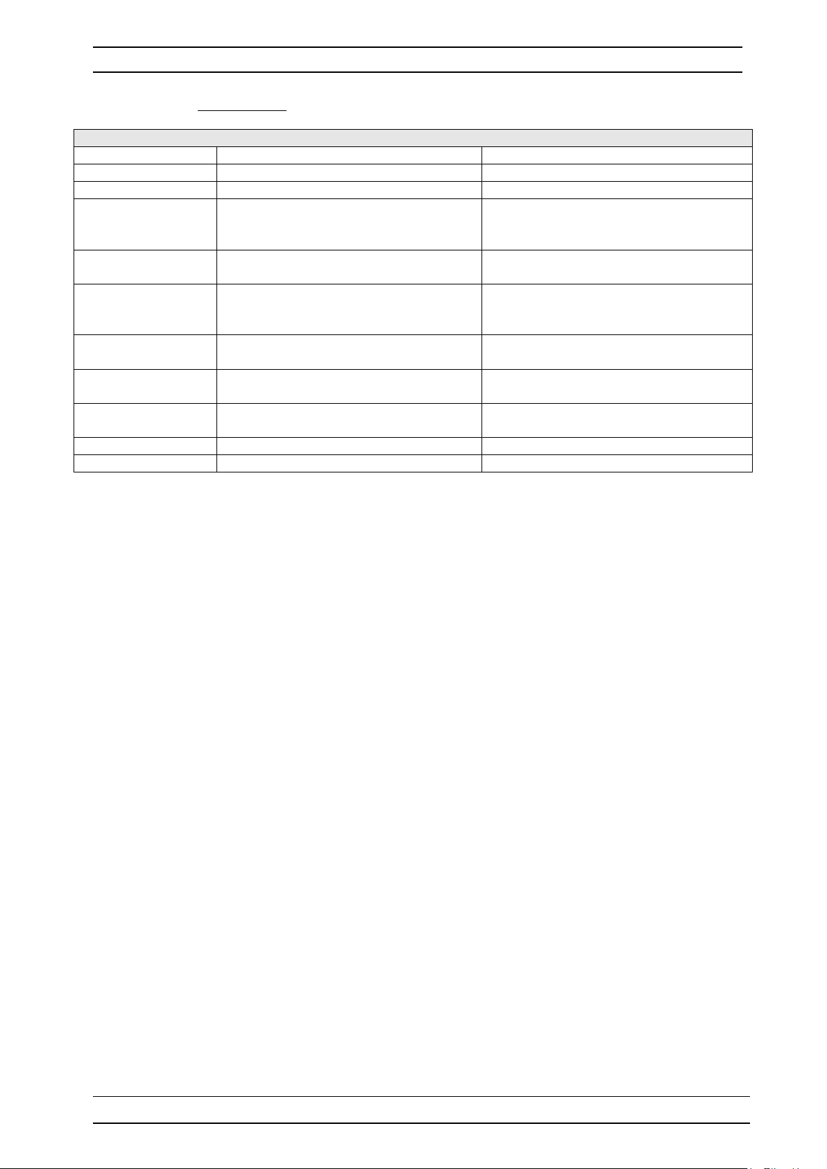
Technical characteristics Page 11/40
Main functions
Function
Specification (s)
Comment(s)
Controls
Controls of the 2 selected parameters
According the version
Trace detection
Total chlorine / Ozone
Specific processes
PWM command
On/Off command with hysteresis
Expressed in real measurement values
Control of top and bottom thresholds
Closed-loop control of injections with an
or with flow-switch control from cell.
Control of each injection channel to one
or two external contact(s). (Flow et Flsw)
Programming of polarisation
depolarisation controls timers
According to the type of measurement
entries.
External communication port with
“MODBUS RTU” supported.
Maintenance
Assistance to maintenance
Checking of general good working
Supervision
Remote supervision via modem
Event tracking
2) Main functions
Actuator type
4x Free of potential relays outputs
0/4…20 mA outputs
Alarms Low, high and technical alarms
Closed-loop control
Remote control
Flow rate control
Level tanks Low level detection for chemical tanks
Timers
Communication RS485 local port half-duplex
Impulse command
external contact (filtering, for example)
Installation and starting instruction manual SYCLOPE TRACE’O
®

Technical characteristics Page 12/40
Measurements and controls
Parameter
Range of measurement
Accuracy
0 to 1mg/l
0 to 0,5mg/l
0 to 5000mg/l
3) Measurement parameters, scales and control ranges
a) Basic versions : Direct entries (2x 4…20mA) or isolated entries (2x 4…20mA)
The main and auxiliary entries are programmable as bellow:
T°C /°K / °F
pH 2 to 11 pH ± 0,5 %
Free chlorine
Active chlorine
Total chlorine (Trace function)
Chlorine dioxide
Chlorites
Bromine
-5 to 45°C
0 to 100°C
0 to 2mg/l
0 to 5mg/l
0 to 10mg/l
0 to 1mg/l
0 to 2mg/l
0 to 5mg/l
0 to 10mg/l
0 to 20mg/l
0 to 50mg/l
0 to 100mg/l
0 to 200mg/l
0 to 250mg/l
0 to 1mg/l
0 to 2mg/l
0 to 5mg/l
0 to 10mg/l
0 to 20mg/l
0 to 0,5mg/l
0 to 1mg/l
0 to 2mg/l
0 to 5mg/l
0 to 10mg/l
0 to 1mg/l
0 to 2mg/l
0 to 1mg/l
0 to 2mg/l
0 to 5mg/l
0 to 10mg/l
0 to 20mg/l
± 0,5 %
± 0,5 %
± 0,5 %
± 0,5 %
± 0,5 %
± 0,5 %
± 0,5 %
Oxygen
0 to 1mg/l
0 to 2mg/l
0 to 5mg/l
0 to 10mg/l
0 to 50mg/l
0 to 100mg/l
0 to 200mg/l
0 to 250mg/l
0 to 500mg/l
0 to 1000mg/l
0 to 2000mg/l
Installation and starting instruction manual SYCLOPE TRACE’O
± 0,5 %
®
 Loading...