

SYCLOPE electronic HYDRO’Com Series, HYDRO’Com HYD 7000, HYDRO’Com HYD 7020, HYDRO’Com HYD 7010 Installation And Commissioning Instructions
Installation and commissioning instructions
References : HYDCOM, HYD7000, HYD7010 and HYD7020 Rev : 1.2
HYDRO’Com® Communication gateway for private swimming pools

General informations Page 2/36
Installation and commissioning instructions manual
General informations :
SYCLOPE Electronique 2016® Manual of February 7th, 2018 Rev:1.2
Installation and commissioning instructions manual
(Ref : DOC0257)
Editor :
SYCLOPE Electronique S.A.S.
Z.I. Aéropole pyrénées
Rue du Bruscos
64 230 SAUVAGNON - France –
Tel : +33 559 337 036
Fax : +33 559 337 037
Email : syclope@syclope.fr
Internet : http://www.syclope.fr
© 2016-2018 by SYCLOPE Electronique S.A.S.
Subject to modifications

Summary Page 3/36
Installation and commissioning instructions manual
Summary
I. General informations ......................................................................................................... 4
1) Applicability ...................................................................................................................... 4
2) Use of the document ......................................................................................................... 5
3) Symbols and signs ............................................................................................................. 5
4) Stockage et transport ........................................................................................................ 6
5) Packaging ......................................................................................................................... 6
6) Warranty .......................................................................................................................... 6
II. Environment and safety procedures .................................................................................... 7
1) Use of the devices ............................................................................................................. 7
2) User obligations ................................................................................................................ 7
3) Risks prevention ................................................................................................................ 7
4) Identification and localization of the identification plate ....................................................... 8
5) Waste disposal and compliance .......................................................................................... 9
III. Technical features and functions .......................................................................................10
1) Technical features ............................................................................................................10
2) Temperature sensor ranges ..............................................................................................10
IV. Installation and wirings .....................................................................................................11
1) Installation conditions .......................................................................................................11
2) Installation of the communication gateway on wall-mounted ..............................................11
3) Branchements électriques .................................................................................................12
4) Localisations of the components and general connections ...................................................12
5) Connection of the primary power supply ............................................................................14
6) Connections of the “free of potential” power relays ............................................................14
7) Connection of the analog 4…20mA entry ...........................................................................14
8) Connection of the “free of potential” entries .......................................................................15
9) Connection of the RS323C ports used to link the HYDRO controllers ....................................15
10) Connection of the RS485 communication bus .....................................................................15
11) Connection of the GSM, Wifi and Ethernet socket MODEM for internet access ......................16
12) References of the HYDRO’Com® communication gateway with included modem ...................17
V. Presentation of myHYDRO interface ...................................................................................18
1) Login ...............................................................................................................................18
2) Main page ........................................................................................................................18
3) Graphic page ...................................................................................................................21
4) Alarm page ......................................................................................................................22
5) Email page .......................................................................................................................22
6) Programming page ...........................................................................................................23
7) Programming control inputs ..............................................................................................24
8) Programming analogue input ............................................................................................25
9) Programming of the time schedule ....................................................................................25
10) Programming the slaves ...................................................................................................26
11) Programming the modem .................................................................................................27
VI. Using the USB stick...........................................................................................................29
1) Configuring the device ......................................................................................................29
2) Updating the internal embedded software ..........................................................................29
3) Blinking of the USB LED ....................................................................................................29
VII. Maintenance.....................................................................................................................30

General informations Page 4/36
Installation and commissioning instructions manual
I. General informations
1) Applicability
The HYDRO’Com® communication gateway you have just purchased is an electronic device
allowing connections to Internet for the various SYCLOPE apparatuses used for the water
management of private swimming pools. It has been carefully developed and manufactured to
ensure your greatest pleasure and peace of mind.
The internal MODEM allows connection to Internet. The HYDRO’Com® communication gateway is
then connected to the web site “myHydro.com” by internet in real-time according its internal
programmed configuration.
Two RS232 ports and one RS485 port allow to establish a local communication with the different
SYCLOPE devices in order to make the data acquisitions and to ensure the programming of the
parameters. The HYDRO’Com® communication gateway can manage up to 5 slaves on the RS485
bus. Slaves connected to the HYDRO’Com® communication gateway by their RS485 ports and the
RS485 link are also connected to the website http://hydro.mysyclope.com/, thus ensuring a total
management and the monitoring of all parameters.
The HYDRO’Com® communication gateways are equipped with four programmable entries free of
potential used to manage specific actuators in swimming pool water’s treatments through four
power relays with free of potential contacts. Four programmable real-time timers are also available
and one 4…20mA entry for temperature measurement.
The simplicity of operation of the HYDRO’Com® communication gateway, the user friendliness
and the remarkable technical aspects of these devices, will ensure you benefit from their many
options, guaranteeing you full control and supervision of the quality of the water in your swimming
pool.
The following instructions contain all the information required for the installation, the use and the
maintenance of your new HYDRO’Com® communication gateway.
➢ Installation
➢ Technical specifications
➢ Commissioning instructions
➢ Safety tips
If you would like to receive further information or if you encounter any difficulties not described in
this manual, please contact your usual retailer or else directly contact the sales department of
SYCLOPE Electronique S.A.S., either at the agency or at the office of your region, or the
technical/quality departments of our establishments. We will do everything in our power to help
you and ensure you benefit from our advice and know-how in the field of measurement and
treatment of swimming-pool water.
Contact : service-technique@syclope.fr

General informations Page 5/36
Installation and commissioning instructions manual
2) Use of the document
Please read this entire document before starting to install, adjust or commission your controller
device, in order to ensure the safety of swimmers, users and equipment.
The information provided in this document must be strictly observed. SYCLOPE Electronique S.A.S.
declines all responsibility in cases where failure to comply with the instructions of this documents is
observed.
The following symbols and pictograms will be used to facilitate reading and understanding of these
instructions.
● Information
► Action to be taken
➢ Item of a list or catalogue
3) Symbols and signs
Identification of a continue voltage or current
Identification of an alternative voltage or current
Protective ground
Functional ground
Risk of injury or accident. Identify a warning concerning a potentially dangerous risk.
Documentation must be consulted by the user with each time the symbol is notified. If the
instructions are not respected, that presents a risk of death, physical injuries or property
damages.
Electric hazard. Identify a warning statement relative to a mortal electric danger. If the
instructions are not strictly respected, that implies an inevitable risk of physical injuries or
death.
Risk of incorrect operation or damage for the device.
Comment or particular information.
Recyclable element.

General informations Page 6/36
Installation and commissioning instructions manual
4) Stockage et transport
It is important to store and transport your HYDRO’Com® communication gateway in its
original packaging in order to minimize risk of damage.
Furthermore, the package must be stored in an environment that is protected against
humidity and exposure to chemical products.
Environmental conditions for transport and storage:
Temperature: -10 °C to 60 °C
Air humidity: Maximum of 90% with no condensation
5) Packaging
The apparatus is delivered without any cable other than that of primary power supply.
The communication gateway is already equipped with mounted cable glands. Additional
cables used must be adapted to the latter to comply with the degree of protection IP65. A
mounting kit is also provided.
Is included in the packaging:
✓ HYDRO’Com
®
communication gateway device,
✓ A complete fixing kit,
✓ The commissioning instruction.
6) Warranty
The warranty is provided according to the terms of our general conditions of sale and delivery as long
as the following conditions are met:
➢ Use of the equipment according to the instructions of this notice
➢ No modifications of the equipment which may modify its behavior and no incorrect
manipulation
➢ Respect for the electrical safety conditions
Consumable material is no longer covered by the warranty when in use
Environment and safety procedures Page 7/36
Installation and commissioning instructions manual
II. Environment and safety procedures
Please:
➢ Read this manual carefully before unpacking, installing or commissioning this equipment
➢ Take into account all the hazards and recommended precautionary measures
Failure to respect these procedures can result in serious injury to users or damage the device.
1) Use of the devices
HYDRO’Com® communication devices have been designed to serve as a gateway to different
SYCLOPE Electronique products or other devices compatible in the context of the possibilities of
use described in this manual.
Any different use is considered improper and must be banned. SYCLOPE Electronique
S.A.S. will not assume any liability and the damages resulting therefrom.
Any use of sensors or non-compliant interfaces to the specifications defined in the operating
instructions must also be banned.
2) User obligations
The user undertakes not to allow its employees to work with the HYDRO’Com® communication device
described in this manual unless they:
➢ Are aware of the fundamental instructions relating to work safety and prevention of accidents
➢ Are trained in the use of the device and its environment
➢ Have read and understood these instructions, warnings and manipulation rules
3) Risks prevention
The installation and connection of the HYDRO’Com® communication gateway should only
be performed by personnel specialized and qualified for this task.
The installation must comply with current safety standards and instructions!
Before turning the device on or manipulating the relay outputs, please, always disconnect
the primary power supply!
Never open the appliance when powered on!
Maintenance operations and repairs must be performed by specialized and authorised
personnel!
Take care when choosing the location for installing the HYDRO’Com® communication
gateway according to the environment!
The HYDRO’Com® communication gateway should not be installed in a hazardous
environment and should be protected against splashing with water or chemical products. It
should be installed in a dry, well-ventilated location, isolated from corrosive vapors.
With the exception of the relay outputs, all connections inputs and outputs must be
connected to very low safety voltages. These tensions are generally provided by the device
and does not exceed 24VDC.
Environment and safety procedures Page 8/36
Installation and commissioning instructions manual
Make sure that the chemical sensors used with this device correspond well to the chemicals
used. Refer to the individual technical note of each sensor. Chemistry of water is very
complex, in case of doubt, contact immediately our engineering service or your approved
installer/reseller.
Chemical sensors are sensitive elements using consumable parts. They must be supervised,
maintained and calibrated regularly using specific calibrator systems not-provided with this
equipment. In the event of defect, a surplus possible hazard of chemical injections can be
noted. In the doubt, a service contract must be taken near your reseller/installer or failing
this near our engineering services. Contact your approved installer/reseller or our business
service for more information.
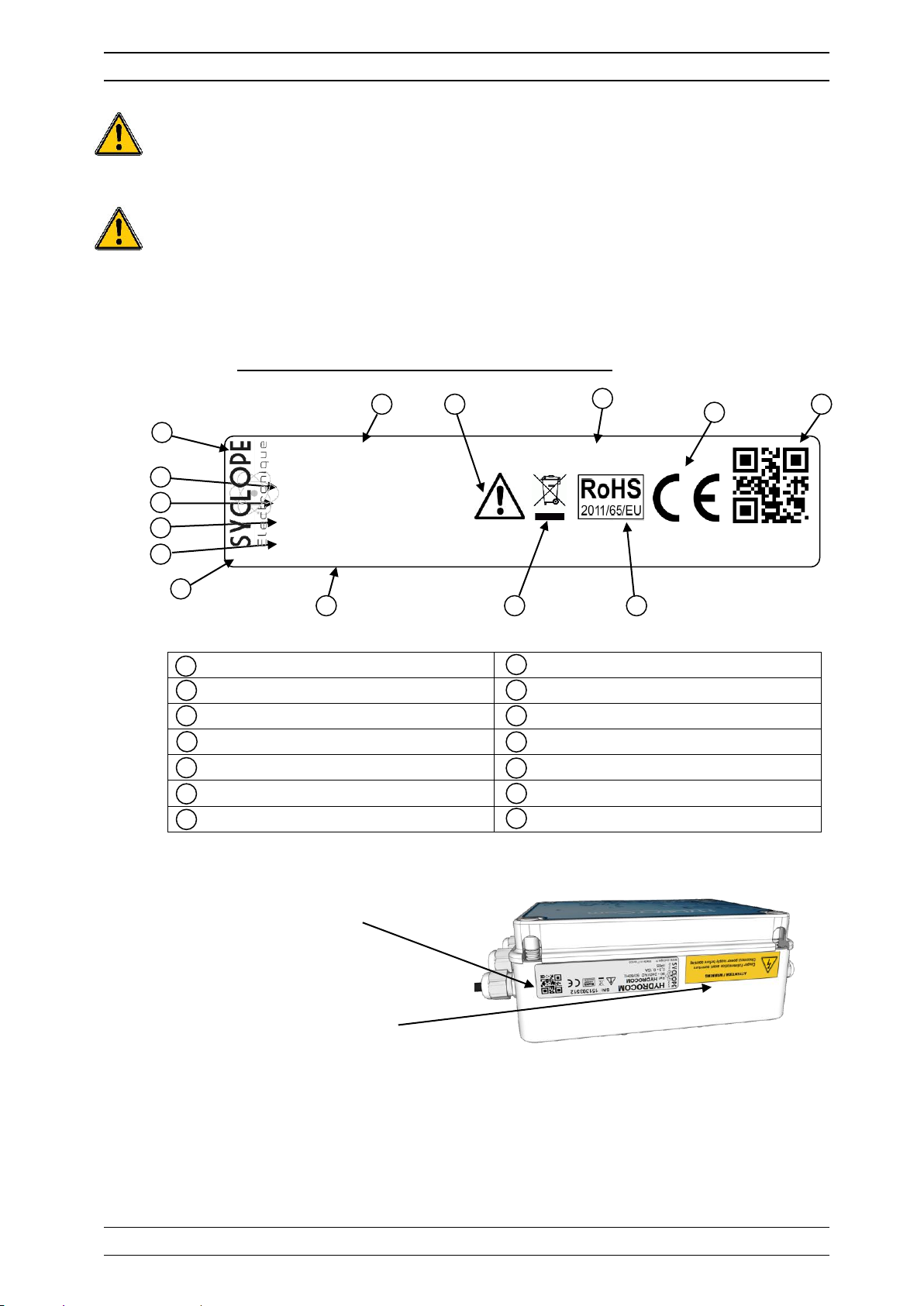
4) Identification and localization of the identification plate
Label of the manufacturer
Serial number
Model of the product
Product which can be recycled
Reference of the product
Limitation of dangerous substances
Power supply range
CE compliance
Maximum current input
Country of the manufacturer
Protection class
Manufacturer square code
Manufacturer identification
Particular risks. Read the manual
Identification plate
Safety instruction sticker
8
9
10
11
12
13
14
1 2 3 4 5
6
7
1
2 3 4 5 6
8
10
11
7
13
14
9
12
HYDRO’Com
Ref: HYD 70x0
90 - 240VAC 50/60Hz
www.syclope.fr Made in France
0,25 - 0,1A
IP65
S/N: 13044217
Environment and safety procedures Page 9/36
Installation and commissioning instructions manual
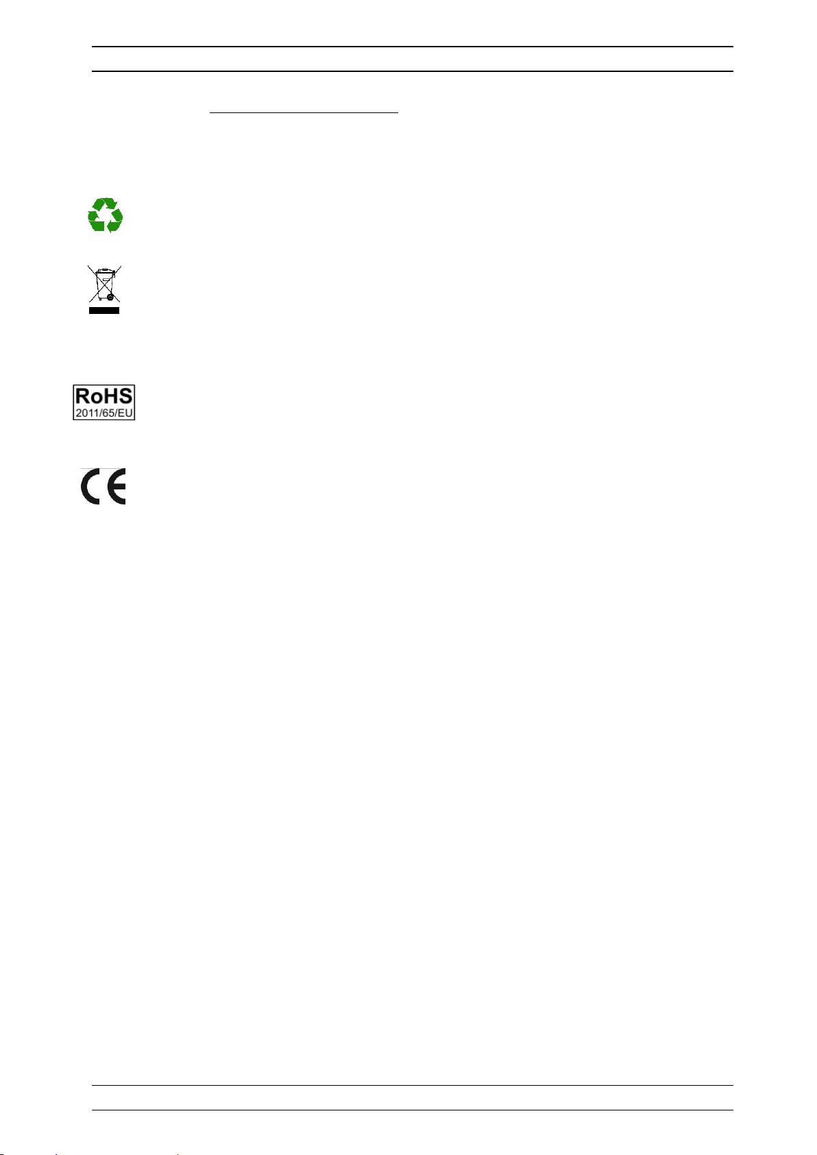
5) Waste disposal and compliance
The recyclable packaging of the HYDRO’Com® devices must be disposed of according to current
regulations.
Elements such as paper, cardboard, plastic or any other recyclable elements must be taken
to a suitable sorting center.
WEEE : According to European directive 2002/96/EC, this symbol means that as of 12
August 2005 electrical appliances cannot be thrown out together with household or industrial
waste. According to current regulations, consumers within the European Union are required,
as of this date, to return their used devices to the manufacturer, who will take care of
disposing them at no extra expense.
RoHs2 : According to the European directive 2011/65/CE, this symbol means that the
HYDRO’Com® communication gateway is manufactured in compliance with the restriction
of hazardous substances.
CE : According to low-voltage directive (2014/35/UE) and the electromagnetic compatibility
directive (2014/30/UE), this symbol means that the HYDRO’Com® communication gateway
has been manufactured in compliance with the previously cited directives.
Technical features and functions Page 10/36
Installation and commissioning instructions manual
III. Technical features and functions
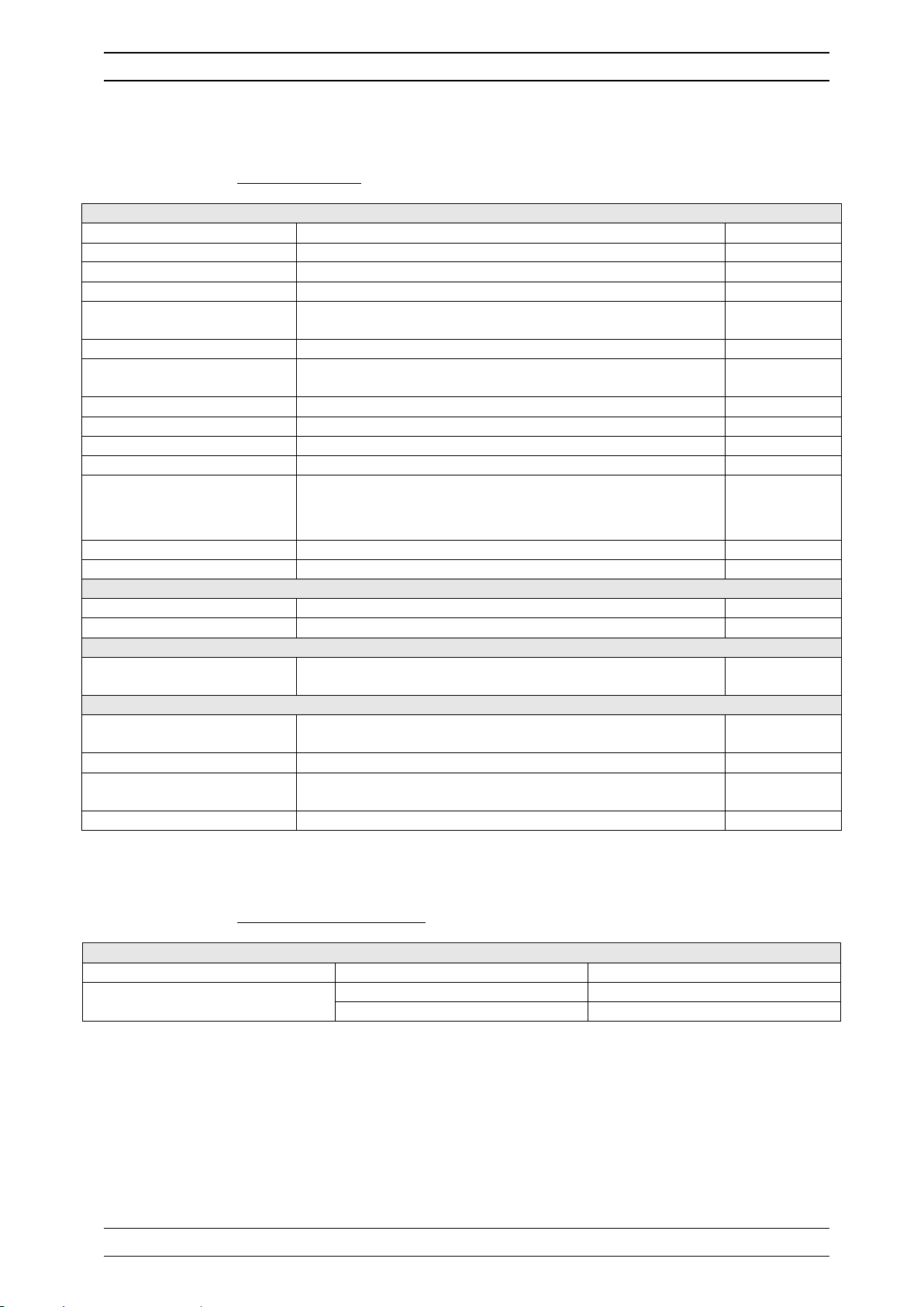
1) Technical features
General characteristics
Type
Specification(s)
Mark(s)
Consumption
0,25A Maxi. (90VAC) to 0,1A Maxi. (240VAC)
-
Power supply requirements
Between 90 to 240VAC +/-10%
-
Voltage category
Class II
Temporary overvoltage
Accept temporary overvoltage from the power supply
system. Electric protection
Fuse 315 mA Time-lag 5x20 Miniature type TR5
F1
Maximum temperatures of
operation
-5 °C to 45°C
-
Storage temperature
-10 °C to 60°C
-
Humidity
Max. 90% without condensation
-
Altitude
Use lower than 2000m
-
Material
ABS
-
Dimensions
Length : 190 mm (7.5 inches)
Width : 140 mm (5.5 inches)
Height : 70 mm (2.75 inches)
-
Weight
0,5 kg - Protection rating
IP 65
-
Entries
Measurement input
1x 4…20 mA current input generating 24VDC
T°C
Control imputs
4x Isolated control input free of potential
E1 to E4
Outputs
Relay outputs
4x Relays free of potential
Max. 2A/250VAC
S1 to S4
Communications
BRS485 Bus
1x Communication port RS485 type for compatible software
protocol type “MODBUS RTU” or “MODBUS ASCII”.
RS485
Modem (Option)
1x Slot for GSM or WiFi or Ethernet socket MODEM
-
RS232 Ports
2x Communication port RS232C for connecting SYCLOPE
HYDRO® controllers.
RS232-1
RS232-2
USB
1x USB port for memory stick
USB
2) Temperature sensor ranges
Measurement and control
Parameter
Range(s)
Accuracy
T°C
-5 to 45°C
± 0,5 %
0 to 100°C
± 0,5 %
Installation and wirings Page 11/36
Installation and commissioning instructions manual
IV. Installation and wirings
1) Installation conditions
To guarantee the users safety and to ensure correct operation of the HYDRO’Com®
communication gateway, please observe strictly the following instructions:
➢ Install the controller in a dry location.
➢ The communication gateway must be protected against rain, frost and direct sunlight.
➢ The room temperature must range between -5°C and 45°C, with no condensation.
➢ Choose an installation location free of vibration, on a suitable support and with no
deformation.
➢
If these instructions are not observed:
➢ The communication gateway is at risk of being damaged
➢ The measurements and communications can be disrupted
➢ The warranty is not applicable!
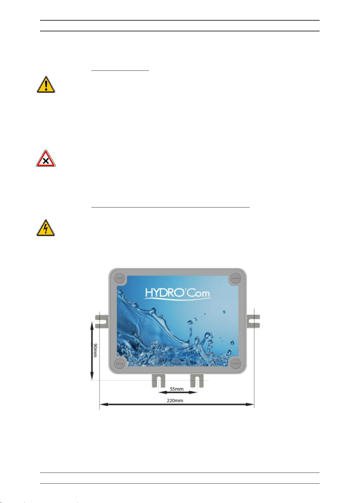
2) Installation of the communication gateway on wall-mounted
Before performing the installation and electrical connections, remember to turn off the
primary power supply!
The IP65 protection’s indice is only guaranteed when the closing cover is closed and when
the cable glands match to the diameters of the cables and are correctly sealed.
► Drilling four holes ( 5-mm) according to the following drilling-plan,
► Insert the 5-mm plugs using a hammer,
► Insert the upper screws (top screw) first without completely tightening it,
► Insert the lower screws and tighten them,
► Tighten the upper screw,
► Use a spirit level to check for correct and accurate fixing to the wall.
 Loading...