


Installation, commissioning and
maintenance instructions
Reference : TUR 20x0 Rev :1.01
On line Turbidity pro b e for swimming-pools “
TURBIPOOL Primary ®”

General informations Page 2/24
Installation, commissioning and maintenance instructions SYCLOPE
« TURBIPOOL Primary® »
General informations :
SYCLOPE Electronique 2017
®
Date : 26/04/2018 Rev : 1.01
On line turbidity probe.
TURBIPOOL
Primary
®
range
Installation, commissioning and maintenance manual (Ref. DOCxxxx)
Editor :
SYCLOPE Electronique S.A.S.
Z.I. Aéropole pyrénées
Rue du Bruscos
64 230 SAUVAGNON - France
Tel : (33) 05 59 33 70 36
Fax : (33) 05 59 33 70 37
Email : syclope@syclope.fr
Internet : http://www.syclope.fr
© 2017 by SYCLOPE Electronique S.A.S.
Subject to modifications

Summary Page 3/24
Installation, commissioning and maintenance instructions SYCLOPE
« TURBIPOOL Primary® »
Summary
I.
Generalities ....................................................................................................................... 4
1) Application areas ............................................................................................................... 4
2) Use of this document ......................................................................................................... 5
3) Signs and symbols ............................................................................................................. 5
4) Storage and transport ........................................................................................................ 6
5) Packaging ......................................................................................................................... 6
6) Warranty .......................................................................................................................... 6
II. Safety and environmental instructions................................................................................. 7
1) Use of the probe ............................................................................................................... 7
2) Obligations of the user....................................................................................................... 7
3) Risks prevention ................................................................................................................ 7
4) Identification and location of the nameplate ........................................................................ 8
5) Elimination and compliance ................................................................................................ 9
III. Technical features ............................................................................................................10
1) Measurements .................................................................................................................10
2) Technical features ............................................................................................................10
IV. Installation and wiring ......................................................................................................11
1) Installation conditions .......................................................................................................11
2) Installation mural de la sonde de turbidité .........................................................................11
3) Electrical connections of the turbidity probe .......................................................................11
4) Identification and connections of the turbidity probe w ires ..................................................12
5) Connection conditions of hy dr auli c tubing ..........................................................................12
V. Standard uses of the turbidity probe ..................................................................................13
1) Control of swimming pool’s water turbidity .........................................................................13
2) Control of the water quality after filtration .........................................................................14
3) Control of the end of the filter backwash cycle ...................................................................14
VI. Calibration procedure ........................................................................................................15
VII. Maintenance procedure .....................................................................................................15
1) Procedure for opening and closing the probe for maintenance operations ............................15
2) Identification of error currents ..........................................................................................19

Generalities Page 4/24
Installation, commissioning and maintenance instructions SYCLOPE
« TURBIPOOL Primary® »
I. Generalities
1) Application areas
The turbidity mea suring probe of the SYCLOPE T URBIPOOL Primary® range that you have just
acquired is a high precision electronic and optical sensor for the measurement and treatment of
swimming pool water. It has been studied and built with care for your great est satisfaction and
your peace of action.
Its remarkable adaptability to the different situations o f the swimming pool applications allows it to
adapt to all difficult environm ents where the measurement processes for the water treatment are
most important.
Designed accordi ng to t he ne ed s of t he final us er, the S YCLOP E TU RBIPOOL
Primary
®
turbidity
probe has a hydraulic inlet and outlet for sampling the water to be measured and a compat ible
connection cable with the "SYCLOPE" controller's brand.
Compliant with the European standard EN27027 (ISO7027), the
SYCLOPE TURBIPOOL
Primary
®
turbidity probe operates on the principle of an infrared beam at 860 nm and a
measurement of turbidity achieved with an optical sensor posit ioned at a 90 ° angle compared to
the emitting beam.
The simplicity of operation of the turbidity sensor
SYCLOPE TURBIPOOL
Primary
®
and the
remarkable technicality of these components, will make you fully enjoy a perfect control and a
perfect monitoring of the water quality of your swimming-pool.
In the following instructions, you will find all informations you need for installing, commissioni ng
and maintaining this new turbidity probe.
Installation
Technical spe c ifications
Commissioning
Safety
If you wish to receive further information or if you encounter any difficulties that ar e not specified
in this manual, contact your usual reseller or contact the after-sales-service department of
SYCLOPE Electronic S.A.S., either at the agency or o ffice in your region , or the technica l / quality
services of our institutions. We will do everything necessary to help you and make you benefit from
our advice and our know-how in the field of measurement and treatment of swimming pool water.
Contact : service-technique@syclope.fr

Generalities Page 5/24
Installation, commissioning and maintenance instructions SYCLOPE
« TURBIPOOL Primary® »
2) Use of this document
Please read this entire document before installing, handling, or commissioning your turbidity probe to
maintain the safety of the swimmers, the technical users or all equipments of the technical room.
Informations given in this document should be scrupulously followed. SYCLOPE Electronique S.A.S
cannot be held responsible for any failure to follow the instructions in this document.
To facilitate reading and understanding of t his manual, the following symbols and pictogra ms will be
used.
● Information
► Action to be done
Element of a list or an enumeration
3) Signs and symbols
Identification of a direct voltage or a direct current
Identification of an alternating voltage or alternating current
Protective electrical grounded
Functional grounding
Risk of injury or accident. Identifies a warning about a potentially dangerous hazard. The
documentation m ust be consulted by the user each time the symbol is notified. Failure to
follow instructions may result in death, personal injury or property damage.
Risk of electric s hock. Ide ntify a warning about a deadly electrical hazard. If the instructions
are not strictly followed, this implies an inevitable risk of personal injury or death.
Risk of malfunction or damage to the device
Note or special information
Recyclable element

Generalities Page 6/24
Installation, commissioning and maintenance instructions SYCLOPE
« TURBIPOOL Primary® »
4) Storage and transport
Storage and transportation of the SYCLOPE TURBIPOOL
Primary
®
turbidity probe must
be carried out in its original packaging to prevent potential damage.
The set should be stored in protected environment from moisture and protected from sun
and chemical exposures.
Beware of possible transporting shocks!! The turbidity probe is an optical probe comprisi ng
fragile glass elements.
Ambient conditions for transport and storage :
Temperature : -10 °C to 60 °C
Humidity : Maximum 90% without condensation
5) Packaging
The turbidity probe is delivered with a power and signal cable at very low voltage.
Included into the packaging :
Turbidity measurement probe SYCLOPE TURBIPOOL
Primary
®
This operating instructi on ma nua l
5m of PE hydraulic tubing corresponding to the used diameter
6) Warranty
The guarantee is insured according to the terms of our general sales conditions and delivery insofar as
the following conditions are met:
Use of the probe according to the instructions in this manual
No modification of the probe likely to modify its beha vior or improper handling
Respect for electrical safety conditions
Consumable material is no longer guaranteed as soon as used.

Safety and environmental instructions Page 7/24
Installation, commissioning and maintenance instructions SYCLOPE
« TURBIPOOL Primary® »
II. Safety and environmental instructions
Please :
Read this manual carefully before unpacking, installing, or commissioning this equipment
Consider all the dangers and recommended precautionary measures
Failure to follow these procedures could result i n ser ious injury or damage to the device.
1) Use of the probe
The SYCLOPE TURBIPOOL
Primary
®
turbidity probe has been designed to measure the turbidity of
the swimming pool water within the scope of use described in this manual.
Any other use is considered as not-compliant and must be prohibited. SYCLOPE Electronique
S.A.S. will not assume any liability and resulting damage.
Any use of sensors or interfaces that do not comply with the technica l specifications defined
in this manual must also be prohibited.
2) Obligations of the user
The user agrees to let working with the SYCLOPE TURBIPOOL
Primary
®
turbidity Probe described
in this manual, only the personnel who:
is aware of the basic instructions on safety at work and accident prevention,
is trained in the use of the device and its environment,
has read and understood this manual, warnings and handling rules.
3) Risks prevention
Installation and conne ction of the SYCLOPE TURBIPOOL
Primary
®
turbidity probe must
only be performed by qualified personnel for this task.
The installation must comply with the standards and safety regulations in force!
Before connecting the probe to the “SYCLOPE Electronique” controller, always switch off the
primary power supply!
Never open the turbidity probe under power supplied!
Maintenance and repairs must only be ca rried out by authorized and specialized personnel!
Be sure to choose the installing area of the turbidity probe according to the environment!
The SYCLOPE TURBIPOOL
Primary
®
turbidity probe should not be installed in a
hazardous environment. It should be protected from direct sunlight, splashing water or
chemicals in a dry and ventilated area isolated from corrosive fumes.
The SYCLOPE T URBIPOOL
Primary
®
turbidity probe is composed of sensitive elements
and has consumable parts. It must be monitored, maintained and checked regularly (see
maintenance proce d ure ). I n ca se of doubt, a mai nte n a nce c ontr act must be esta bl ished wi th
your authorized installer or, failing t his, with our commercial or te chnical services. C ontact
your installer or our sales department for more information.
Safety and environmental instructions Page 8/24
Installation, commissioning and maintenance instructions SYCLOPE
« TURBIPOOL Primary® »
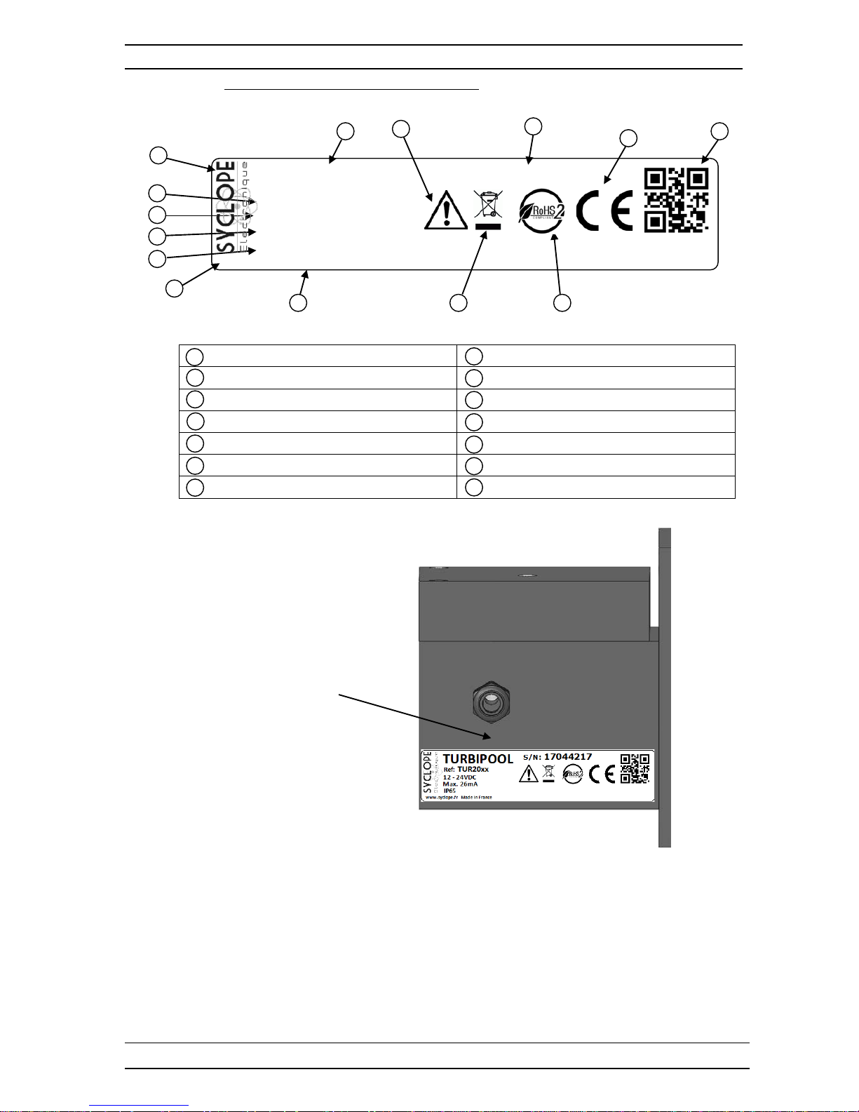
4) Identification and location of the nameplate
Manufacturer’s la bel Serial number
Product model Warning! Read the instructions
Product reference Specific recyclable product
Power supply range Limitation of dangerous substances
Maximum current value CE compliant
Protection class of the case Native country
Manufacturer identification Manufacturer’s square code
Nameplate
8
9
10
11
12
13
14
1
2 3 4
5
6 7 1
2 3 4 5 6
8
11
12
7
14
13
10
9
TURBIPOOL
Ref: TUR20xx
12 - 24VDC
www.syclope.fr Made in France
Max. 26mA
IP65
S/N:
17044217

Safety and environmental instructions Page 9/24
Installation, commissioning and maintenance instructions SYCLOPE
« TURBIPOOL Primary® »
5) Elimination and compliance
Recyclable packaging of SYCLOPE TURBIPOOL
Primary
®
turbidity probe must be disposed of
according to the rules in force.
Items such as paper, cardboard, plastics or any other recyclable eleme nt must be brought to
a suitable sorting center
In accordance wi th the Euro pean Direct ive 2012/1 9/EU, this s ymbol indi cates that from July
4
th
, 2012, electrical appliances can no longer be disposed of in household or industrial waste.
In accordance wit h the regula tions in force , consumer s in the E uropean Uni on are req uired,
from this date, to return their old equipment to the manufacturer who will take care of their
disposal without any charge.
According to the European Directive 2011/65/EU, this symbol indicates that the SYCLOPE
TURBIPOOL
Primary
®
turbidity probe has been designed respecting the limitation of
hazardous substances
In accordance with the Low Voltage Directive (2014/35/EU), the Electromagnetic
Compatibility Directive (2014/30/EU) and the RoHs2 Directive (2011/65/EU), this symbol
indicates that the SYCLOPE TURBIPOOL
Primary
®
turbidity probe has been designed in
accordance with the guidelines mentioned above.

Technical features Page 10/24
Installation, commissioning and maintenance instructions SYCLOPE
« TURBIPOOL Primary® »
III. Technical features
1) Measurements
Turbidity measurement probes are a vailable with standard measurement scales. The y respond to all
possible situations of the swimming pool applications.
Reference
Designation
TUR2010
Turbidity probe TURBIPOOL
Primary
Range 0 – 10NTU
TUR2020
Turbidity probe TURBIPOOL
Primary
Range 0 – 20NTU
2) Technical features
General characteristics
Type
Specification(s)
Location(s)
Case dimensions
Death : 105 mm (4,13 inches)
Height : 125 mm (4,92 inches)
Width : 170 mm (6,69 inches)
-
Case materials
POM or black PVC
-
Measuring tank
Borosilicate glass
Hydraulic connections
Quick connector for PE or PTFE tubing (8x5mm)
Max. pressure
2 bars Max. temp. of water
0 to 50°C (32°F to 122°F)
Primary power supply
Between 12 ~ 35VDC isolated
0V – V+
Consummation
0,26 mA Maxi.
-
Signal output
0/4 … 20mA (Passive output : need to be supplied)
Loop power supply
Mini : 7,5VDC + (R(Charge) x 0,02A)
In/Out isolation
109Ω minimum
Working temperature
-5 °C to 45 °C (23°F to 113°F)
-
Storage temperature
-10 °C à 60 °C (14°F to 140°F)
-
Humidity
Max. 90% without condensation
-
Measured value
Turbidity in N TU
IR wave length
Infrared at 860 nm
Type of measurement
Diffused at 90° according EN27027 (ISO7027)
Response time
< 60 seconds
Maxi. Altitude
< 2000m Case weight
1,6 kg (without liquid)
-
Protection rating
IP 65
-
Output(s)
Analogical output
1 Analogical output 0/4…20 mA Max 500 Ω passive
IA-IB
Currents error values
2,4 mA
Internal measurement system fault (Factory return)
3,8 mA
Low offset measurement out of limits
22,5 mA
High value measurement out of range of probe

Installation and wiring Page 11/24
Installation, commissioning and maintenance instructions SYCLOPE
« TURBIPOOL Primary® »
IV. Installation and wiring
1) Installation conditions
To ensure the safety of the users and to ensure the correct operation of the SYCLOPE
TURBIPOOL
Primary
®
turbidity probe, please observe the following installation
instructions:
Install the turbidity probe in a dry and ventilated area,
The turbidity probe must be protected from rain, frost and direct sunlight,
The ambient temperature must be between 0 and 50 °C without condensation,
Choose a place of installation without vibration, on a clean and undistorted support.
In case of no-complia nce with these instructions:
The turbidity probe and its fragile elements may be damaged
Measurements can be disturbed
The guarantee will not be accepted!
2) Installation mural de la sonde de turbidité
Before processing to wire electrical connections, switch off power of the controll er!
The IP65 rating is only guaranteed if the top closure cover is tightened and correctly
positioned. Under no circumstances should this cover be opened during normal operation.
► Draw the holes to be drilled according to the plan below, checking horizontality with a level tool,
► Drill the 4 holes ∅ 6 mm and insert the dowels using a hammer,
► Attach the 4.5mm top screw (top left screw) first and tighten partially,
► Position the other 4.5mm lower screws and tighten them,
► Tighten the upper screw,
► Ensure the stability of the probe and its horizontality.
3) Electrical connections of the turbidity probe
The SYCLOPE TURBIPOOL
Primary
®
turbidity probe is supplied wit h a 4-wire cable of 5m as
standard. This cable can be extended with an identical or compatible cable.
150mm
105mm

Installation and wiring Page 12/24
Installation, commissioning and maintenance instructions SYCLOPE
« TURBIPOOL Primary® »
Electrical installations must be carried out according to the standards in force and by
authorized personnel!
However, the electrical connections are at low voltage (below 35VDC).
Before connecting the turbidity probe, sw itch off the power supply of the controller!
On the controller side, preferably use crimped cable ends to ensure that no wire can come
into contact with neighbouring cables!
Secure the wire connections to the terminal blocks using clamps.
The SYCLOP E TURBIPOOL
Primary
®
turbidity probe does not have internal fuse . Do not
open when powered!
4) Identification and connections of the turbidity probe wires
The SYCLOPE TURBIPOOL
Primary
®
turbidity probe must be powered by an external
voltage power supply (between 12V to 35V DC). In general, this primary power supply is
provided by the SYCLOPE or compatible measuring device.
Red : Positive voltage (12~35VDC)
Brown : Ground voltage (0V)
Blue : Unpolarised 4…20mA loop
Green : Unpolarised 4…20mA loop
The 4…20mA output current loop is passive sig nal. It is therefore necessary to provide an
additional power supply to ensure the operat ion of the loop. I n general, this pow er supply is
provided by the SYCLOPE controller.
The SYCLOPE TURBIPOOL
Primary
®
turbidity probe does not have a power supply
switch. It is immediately powered when connected to the device.
5) Connection conditions of hydraulic tubing
The SYCLOPE TURBIPOOL
Primary
®
turbidity probe must be supplied with swimming
pool water and with the supplied tubing.
In all cases, the 8x5mm tubing diameter must not be changed!
The sampling flow-rate must be constant and can be set by one of the SYCLOPE series
housing chamber containing a micrometric adjustment device.
No filter system or sampling flow-rate adjustment should be installed BEFORE the turbidit y
measuring probe!

Standard uses of the turbidity probe Page 13/24
Installation, commissioning and maintenance instructions SYCLOPE
« TURBIPOOL Primary® »
V. Standard uses of the turbidity probe
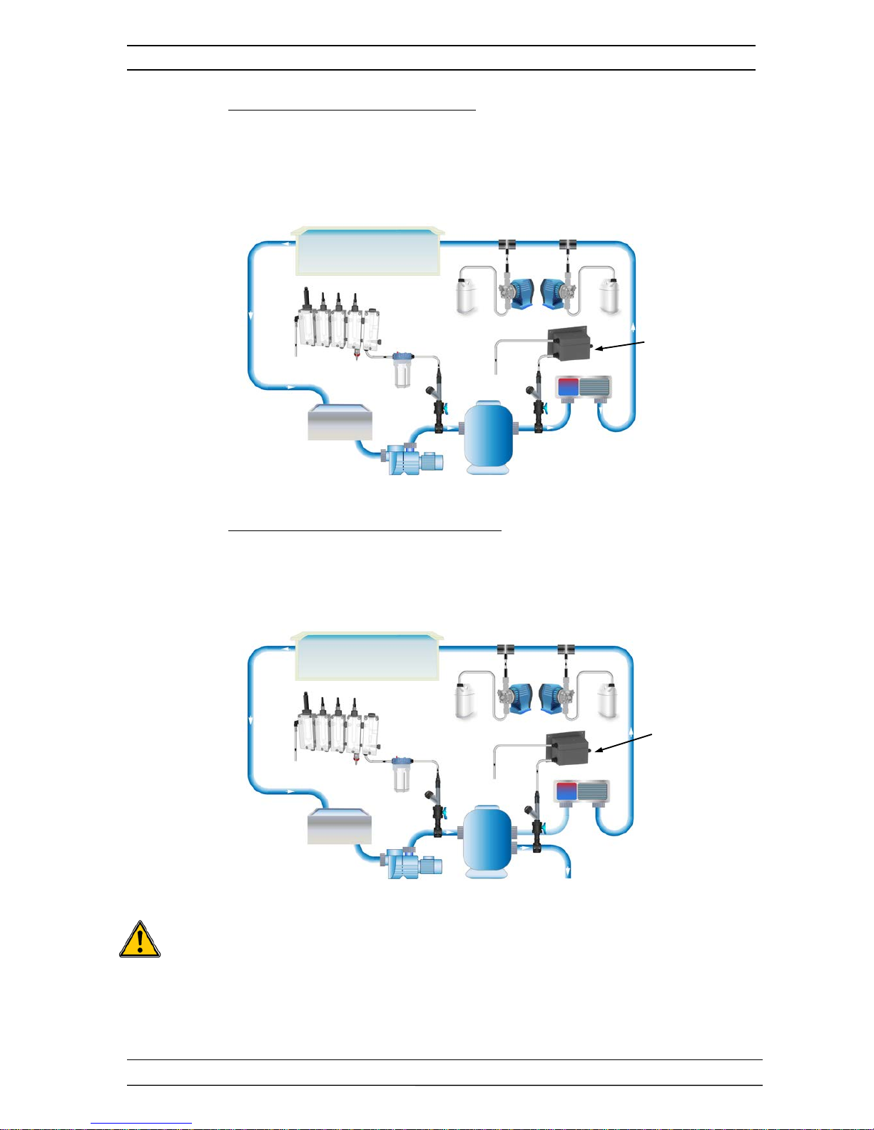
1) Control of swimming pool’s water turbidity
The SYCLOPE TURBIPOOL
Primary
®
turbidity probe is used to measure the
transparency of pool water to prevent a potential hazard to swimmer monitoring.
a) General principle of installation by coring basin:
Mini. 40cm under the water level
This is the closest method to the reality. The sampling must be made at least 40cm
below the top level water of the basin in order to refle ct the true turbidity value. No
presence of air bu bbles or emulsions should be not ed. Do not take the sample under
overflow or increase the sampling depth if this is the case. The proximity of bathers can
cause a disturbance of the sample. Installation near a discharge outlet or water moved
by aquatic-plays must be prohibited.
b) Alternative “on-line solution” with measuring probe housings:
More easily, the sampling can be do ne in line before the measuring probe-housings with
sensors for water analysing. However, the risk of measuring water disturbance can be
accentuated by:
• The water supply in the balancing tank (emulsion),
• The significant return of polluted surface waters,
• An air intake in the filtration pump(s) circuit.
The turbidity probe must be installed before the measuring probe-housing and be fore a p refilter if it is present.
Main filter
Circulation pump
Balancing tank
Turbidity probe
Probe-housings
To the vaste
Filter
Swimming pool
Standard uses of the turbidity probe Page 14/24
Installation, commissioning and maintenance instructions SYCLOPE
« TURBIPOOL Primary® »
2) Control of the water quality after filtration
the SYCLOPE TURBIPOOL
Primary
®
turbidity probe is used to measure the water
quality at the outlet of the filter unit and thus control the overload of the filter(s). As
soon as the turbidity reaches a user-de fined threshol d, the filter ba ckwashing proce ss is
initiated (manually or automatically). Once this process is complete, the turbidity
measurement goes down and the filtration cycle resumes until the next backwash cycle.
3) Control of the end of the filter backwash cycle
The SYCLOPE TURBIPOOL
Primary
®
turbidity probe is use d to measure the quality
of the filter's outlet b ackwash wa ter. When the t urbidity me asurement of the backwash
water returns within a use r-defined threshold, the process is reversed and the filter is
again switched to the washing position.
WARNING: For this last a pplication, the pro be mainte nance m ust be rigorously f ollowed and
carried out more frequently. Indeed, the outlet water of the filter is very charged with
flocculant and other impurities and can cause sig nificant de posits o n the inter nal glass o f the
probe and could cause measurement errors. A solenoid valve solution can be implemented
so that the control condition is made after a user-defined time to control the end of the
backwash cycle.
Filter
Waste
Circulaion pump
Balancing tank
Turbidity probe
Heater
Measuring probe housing
Swimming pool
Pre -filter
Waste
pH Cl
Swimming pool
Prefilter
Circulation pump
Filter
Waste
Waste
Waste
Turbidity probe
pH Cl
Outlet of
backwash water
Measuring probe housing

Calibration and maintenance of the turbidity probe Page 15/24
Installation, commissioning and maintenance instructions SYCLOPE
« TURBIPOOL Primary® »
VI. Calibration procedure
Normally, the SYCLOPE TURBIPOOL
Primary
®
turbidity probe has factory int ernal calibration and
is without local calibration.
If necessary, the offset and the slope of the probe must be externally adjusted using the associated
SYCLOPE device. If it is impossible to use the calibration procedures, refer to the maint enance se ctio n
of this manual.
VII. Maintenance procedure
Maintenance of the SYCLOPE TURBIPOOL
Primary
®
turbidity probe consists only to clean the
internal circulation circuits of the water to be analysed, cleaning or replacing the borosilicate glass tub
and changing his seals.
1) Procedure for opening and closi ng the probe for maintenance operations
WARNING : Before opening the turbidity probe block, make sure that the water supply
circuit is well insulated and without pressure. Any water splashing inside the probe can
destroy the optical measuring system!
To make the maintenance of the SYCLOPE TURBIP OOL
Primary
®
turbidity probe, you need the
following tools and products :
A Allen wrench (hexagonal) of 4mm,
A flat screwdriver with a width size of 3mm,
A cleaning paper kit for lenses or mirror,
A maintenance kit comprising a borosilicate glass tub and two O-ring seals.
A soft absorbent cloth,
A small bottle of demineralized water.
a) Cut the water circuit by disconnecting the two 8/5 quick coupling and empty the probe,
ATTENTION : Do not shock the tur bidity probe during the operation!

Calibration and maintenance of the turbidity probe Page 16/24
Installation, commissioning and maintenance instructions SYCLOPE
« TURBIPOOL Primary® »
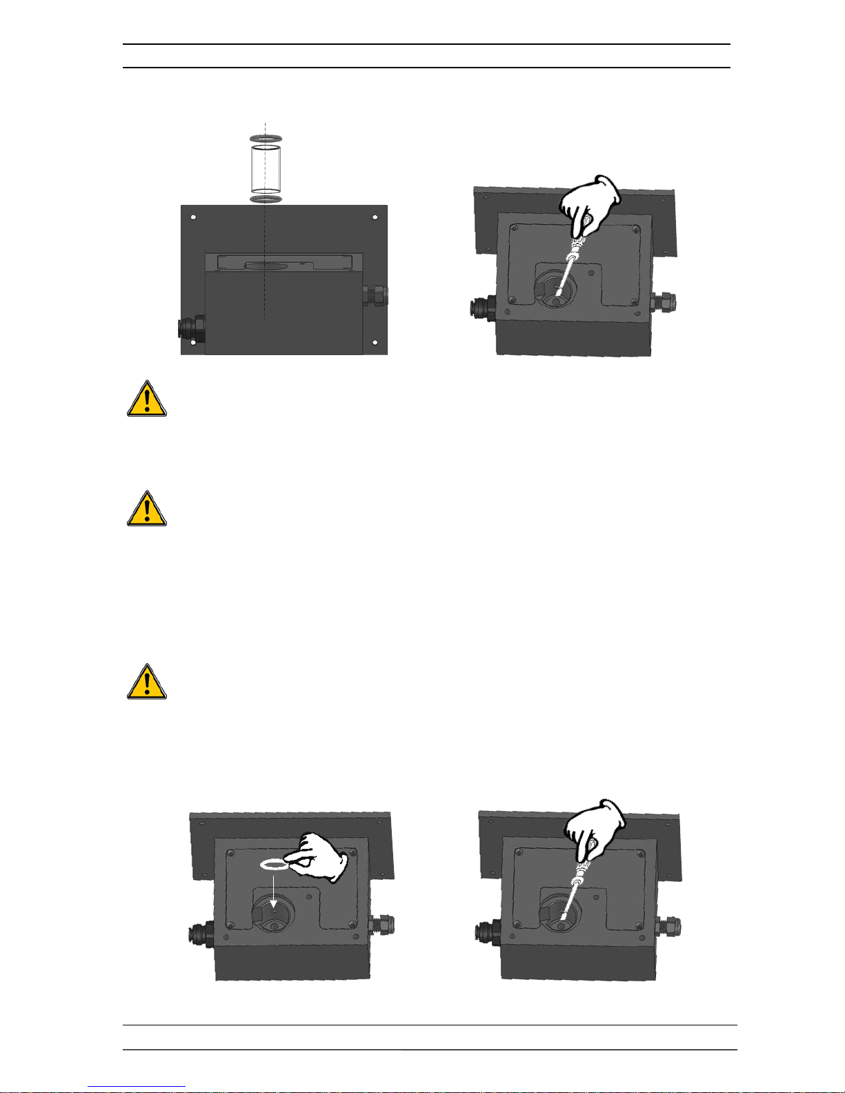
b) Using the Allen wrench to open the top of the turbidity probe
During this operation, take care to maintain the probe vertically so that the internal
borosilicate glass tub and O-ring seals are not ejected or lost!
WARNING : Destruction risk of the borosilicate glass tub !!
c) Remove the 3 hexagonal screws M4x40 using the Allen wrench, put the set of scre ws aside
and lift the top cover of the probe taking care not to drag the borosilicate glass tub out of its
housing.
Check that the O-ring seal is not stuck to the top c over seat and if so, take it off carefully
and replace it when reassembling.
d) Remove the upper O-ring seal and gently remove the borosilicate glass tub vertically …
WARNING : Do not touch the circular surface of the borosilicate glass tub!
Risks to deposit greasy particles from your fingers on the walls of the glass
causing a drift of the probe’s zero point!
Calibration and maintenance of the turbidity probe Page 17/24
Installation, commissioning and maintenance instructions SYCLOPE
« TURBIPOOL Primary® »
e) Using the 3mm screwdriver, remove the lower O-ring seal located at the bottom of the
turbidity probe’s body following the assembly shown be low…
WARNING : Do not mark the inner of the probe’s body with the screwdriver!
f) Clean inside of the pro be’s body with a silky white paper or a piece of clean cloth without
forcing and without additional liquid product!
WARNING : Do not use liquid products for internal cleaning! Risk o f introducing liquid into
both optical conduits! In this case, take care to eliminate all traces of moisture before
reassembly.
g) Preparing the reassembly of the O-ring seals and the borosilicate glass tub
Perform coarse cleaning of the borosilicate glass tub unde rwater a nd without de tergent and
dry it without putting his fi nge rs on the inner and out er surfa ces of the glass tub. Do not dry
with abrasive material! Preferably use a soft cloth.
Using the cleaning’s paper kit for opti c lens, finish cleaning the boro silicate glass tub, taking
care not to touch the inner and outer surfaces with your fingers.
Do not reuse the O-ring seals and change them IMPERATIVELY by a new kit !
h) Reassembling the bottom O-ring seal and the borosilicate g lass tub
Proceed reassembling the bottom O-ring seal and place it in its inner imprint using the 3mm
screwdriver...

Calibration and maintenance of the turbidity probe Page 18/24
Installation, commissioning and maintenance instructions SYCLOPE
« TURBIPOOL Primary® »
i) Reassembling the borosilicate glass tub without touching his surfaces in the opposite way to
dismantling ...
j) Position the upper O-ring se al on the turbidity probe’s cover and position it on top of the
lower block ...
k) Tighten the M4x40 fixing screws by "crossing mode operation" in order to balance the
clamping force and to prevent breaking the borosilicate glass tub ..., then reconnect the
tubings, fill the circuit with water and check the sealing.
If the zero value (small offset) is not automatically achieved, resume the maintenance
procedure and try to understand the reasons of the malfunction! (Check the current error
value to identify the origin of the fault ...)

Calibration and maintenance of the turbidity probe Page 19/24
Installation, commissioning and maintenance instructions SYCLOPE
« TURBIPOOL Primary® »
2) Identification of error currents
The SYCLOPE TURBIPOOL
Primary
®
turbidity probe is equipped with an automatic error detection
system. In case of malfunction, an output current i s automatically generated depending on the type of
error encountered.
Of course, an interpretation of the result must be performed by the user in order to diagnose the
possible reasons of the malfunction.
To perform this test, the probe must normally be connected to the SYCLOPE device and connected to
the sampling circuit.
In normal operation, the turbidity probe generates a proportional current output according to the
chosen range.
Generated current (mA)
Probable reason(s) of the malfunction
4…20mA
Normal working.
The generated current (Igen) is proportional to the turbi dity measured
according to the range of the probe:
For a turbidity probe with a range of 0…10NTU (EM),
If the turbidity measurement (Meas.) is 5,00 NTU, the theoric
generated current will be:
I(gen) = [(Meas./EM) * (20 – 4)] + 4 means 12mA
In fact, a small offset is automatically generated b y the probe for
balancing the mechanical errors and to be sure the signal will be over
4mA minimum. A zero calibration must be performed with distilled
water (see calibration procedure)
2,4mA fixed
Significant anomaly detected by the integrated processor.
Check the following points:
• Internal sea ling of the turbidity probe
(Linkage around the borosilicate glass tub)
(Borosilicate glass tub broken)
• Borosilicate glass tub obstructed, striped or very dirty
• Electronic circuit destroyed or water inside
If the turbidity probe cannot be repaired, please send it back to your
reseller or by fault, to the manufacturer address.
3,8mA fixed
Malfunction of the optical measuring system.
Check the following points:
• Cleanliness of the borosilicate glass tub
(Proceed to internal cleaning according maintenance procedure)
22,5mA fixed
Excess of measurement or exceeding the scale of measurement
Check the following points:
• Cleanliness of the borosilicate glass tub
(Proceed to internal cleaning according maintenance procedure)
• Moisture deposit on the measuring glass tub or on the internal
optics
(Proceed to internal cleaning according maintenance procedure)
(Check the presence of moisture on the glass tub and clean it, look
for the origin of the phenomenon, check the ambient temperature
and the fluid temperature ...
• Operating error of a sensor or IR transmitter
After checking, if the fault persists, please send back the probe to
your reseller or by fault, to the manufacturer address.

Notes Page 20/24
Installation, commissioning and maintenance instructions SYCLOPE
« TURBIPOOL Primary® »

Notes Page 21/24
Installation, commissioning and maintenance instructions SYCLOPE
« TURBIPOOL Primary® »
NOTES

Notes Page 22/24
Installation, commissioning and maintenance instructions SYCLOPE
« TURBIPOOL Primary® »

Page 23/24
Installation, commissioning and maintenance instructions SYCLOPE
« TURBIPOOL Primary® »

SYCLOPE Electronique S.A.S.
Z.I. Aéropole pyrénées
Rue du Bruscos
64 230 SAUVAGNON - France –
Tel : (33) 05 59 33 70 36
Fax : (33) 05 59 33 70 37
Email : syclope@syclope.fr
Internet : http://www.syclope.fr
© 2017 by SYCLOPE Electronique S.A.S.
 Loading...