

Page 1

SYCLOPE ODISEA® Controller for public swimming pools (Part 2)
Programming instructions
Reference : ODI0001 and ODI0002 Rev : 2
Page 2

General informations Page 2/33
Parts of the general documentation
Part 1 : Installation and starting instructions
►
Part 2 : Programming instructions
General informations :
SYCLOPE Electronique 2011® Notice of 14/02/2011 Rev 2
Professional Analyzers/Controllers for public swimming pools.
Product line ODISEA
®
Part 2 : Programming instructions (Ref : DOC0184)
Editor :
SYCLOPE Electronique S.A.S.
Z.I. Aéropole pyrénées
Rue du Bruscos
64 230 SAUVAGNON - France –
Tel : (33) 05 59 33 70 36
Fax : (33) 05 59 33 70 37
Email : syclope@syclope.fr
Internet : http://www.syclope.fr
© 2010 by SYCLOPE Electronique S.A.S.
Subject to modifications
®
Programming instructions SYCLOPE ODISEA
Page 3

Contents Page 3/33
Contents of the documentation
I. Use of the document...................................................................................................................4
II. Safety and environmental instructions.........................................................................................5
1) Use of the equipment .............................................................................................................5
2) User obligations......................................................................................................................5
I. Description of the human-machine interface...............................................................................6
1) Display and control keypad.....................................................................................................6
2) Internal connections..............................................................................................................7
3) Connection terminal boards ....................................................................................................7
II. Structure and index of the programming menus..........................................................................8
1) Menu structure .......................................................................................................................8
2) Tree structure and programming index...................................................................................8
III. User Menu ..................................................................................................................................9
1) Access to technician level........................................................................................................9
2) Choice of language................................................................................................................9
3) Time adjustment .................................................................................................................10
4) Display management ............................................................................................................10
5) Histories ...............................................................................................................................11
6) Maintenance of the device ....................................................................................................13
IV. Technician Menu.......................................................................................................................16
1) Specialist menu access .........................................................................................................16
2) Technician Code ...................................................................................................................16
3) Adjustment of the system date .............................................................................................17
4) Programming a setting point.................................................................................................18
5) Calibration of a measurement parameter..............................................................................18
6) Programming of the general timers.......................................................................................20
7) Programming the scale of analogue outputs .........................................................................23
8) Programming the alarm thresholds .......................................................................................24
V. Specialist Menu.........................................................................................................................25
1) Factory code.........................................................................................................................25
2) Configurations ......................................................................................................................26
3) Initializations ........................................................................................................................29
VI. Table of events and alarms histories.........................................................................................31
Programming instructions SYCLOPE ODISEA
®
Page 4

Use of the document Page 4/33
I. Use of the document
Please read this document in its entirety before starting to program your controller device, in order to
ensure the safety of the swimmers, users and equipment.
The information provided in this document must be strictly observed. SYCLOPE Electronique S.A.S.
declines all responsibility in cases where there is a failure to comply with these instructions of this
document.
The following symbols and pictograms will be used to facilitate reading and understanding of these
instructions.
● Information
► Action to be taken
Item of a list or catalogue
Risk of injury or accident
Electric hazard
Risk of incorrect operation or damage to the device
Comment
Recyclable element
Programming instructions SYCLOPE ODISEA
®
Page 5

Safety and environmental instructions Page 5/33
II. Safety and environmental instructions
The programming you will perform will modify the operation of the controller. For this reason,
it is requested to read these instructions carefully before changing the controller
configuration. Only authorized personnel with suitable training should program the SYCLOPE
ODISEA®.
Please:
Read this manual carefully before unpacking, installing or commissioning this equipment
Take into account all the hazards and recommended precautionary measures
Failure to follow these procedures could result in serious injury to users or damage to the
device.
1) Use of the equipment
The SYCLOPE ODISEA® system has been designed to measure and control pH and chlorine or
bromine by means of sensors and controls of suitable actuators in the context of the possible uses
described in this manual.
All other uses are considered to be not conforming and must therefore be forbidden. SYCLOPE
Electronique S.A.S. will not be responsible in any case for any damages that result from bad
uses.
2) User obligations
The user undertakes not to allow its employees to work with the SYCLOPE ODISEA® equipment
described in this manual unless they:
Are aware of the fundamental instructions relating to work safety and prevention of accidents
Are trained in the use of the device and its environment
Have read and understood these instructions, warnings and functionality
Programming instructions SYCLOPE ODISEA
®
Page 6

Description of the human-machine interface Page 6/33
1
2
2
1
I. Description of the human-machine interface
1) Display and control keypad
Backlit 64x128 display with white text on blue background
Injection and alarm LEDs
Menu button: provides access to the programming menu (yellow LED)
Calibration button: enables the sensors to be directly calibrated
STOP/START button: switches the regulators on or off (green LED)
Clear button: deletes the settings or moves back in the programming menus
Enter button: confirms the settings or moves forward in the programming menus
Up button: can be used to scroll through the menus and increase values
Down button: can be used to scroll through the menus and reduce values
®
Programming instructions SYCLOPE ODISEA
Page 7

Description of the human-machine interface Page 7/33
1
7
2
3
4
5
6
1
2 3
4
5
6
7
2) Internal connections
General protection fuse (glass 5x20 315 mA time-lag fuse)
Relay protection fuse (glass 5x20 2A time-lag fuse)
Connection terminal blocks (see diagram at the bottom of the page)
Modem connector
Location for modem socket (optional)
Printer connector
Connector for ribbon cable to the top card
3) Connection terminal boards
®
Programming instructions SYCLOPE ODISEA
Page 8

Structure et index des menus de programmation Page 8/33
II. Structure and index of the programming menus
1) Menu structure
The programming of the SYCLOPE ODISEA® is broken down into three menu levels. It is possible to
generate access codes for each level. From the simple user level to the specialist level, the device
provides access to increasingly technical settings for the operation of the machine and for the safety of
the process and people.
User Menu: to follow up measurements and calibration
Technician Menu: to modify basic elements such as settings, alarms, etc.
Specialist Menu: for complete modification of the machine's configuration
2) Tree structure and programming index
Menu Function Page
Technician level 9
Language/Language/… 9
User
Set the time 10
Displays 10
Histories 11
Device maintenance (unblocking in specialist level) 13
Specialist level 16
Technician code 16
System date 17
Technician
Setting(s) 18
Calibrations 18
General timers 20
Analogue outputs 23
Alarms 24
Factory Code 25
Configurations 26 Specialist
Initializations 29
Programming instructions SYCLOPE ODISEA
®
Page 9

User menu Page 9/33
…….…......
User Menu
..…
......…
…….…......
Technician Menu
..…......…
…….…......
User Menu
..…
......…
…….…....
..
Technician Menu
..…......…
…….…......
User Menu
..…
......…
…….…......
User Menu
..…
......…
…….…......
User Menu
.. …......…
…….…......
User Menu
..…
......…
…….…......
User Menu
..…
......…
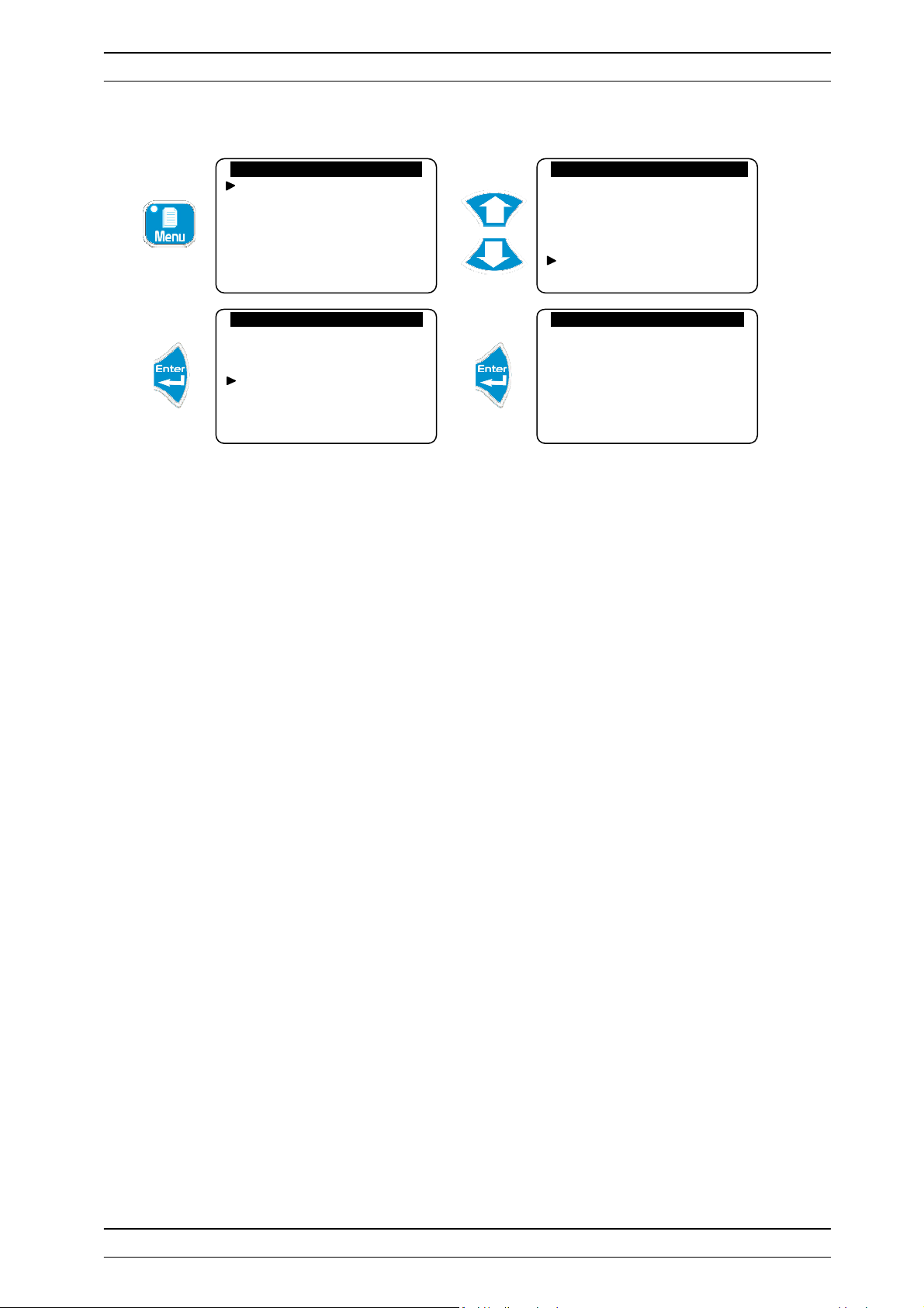
III. User Menu
To access the User Menu, press the button. You now have access to user-level adjustments.
Technician level
Langue/Language/…
Set the time
Displays
Histories
1) Access to technician level
To access the technician menu.
Technician level
Langue/Language/…
Set the time
Displays
Histories
Specialist level
Technician code
System date
Setting(s)
Calibrations
General timers
Analogue outputs
If a code is registered:
Technician level
Langue/Language/…
Set the time
Displays
Histories
Access code : 0 . . .
Enter the access code to enter the technician menu
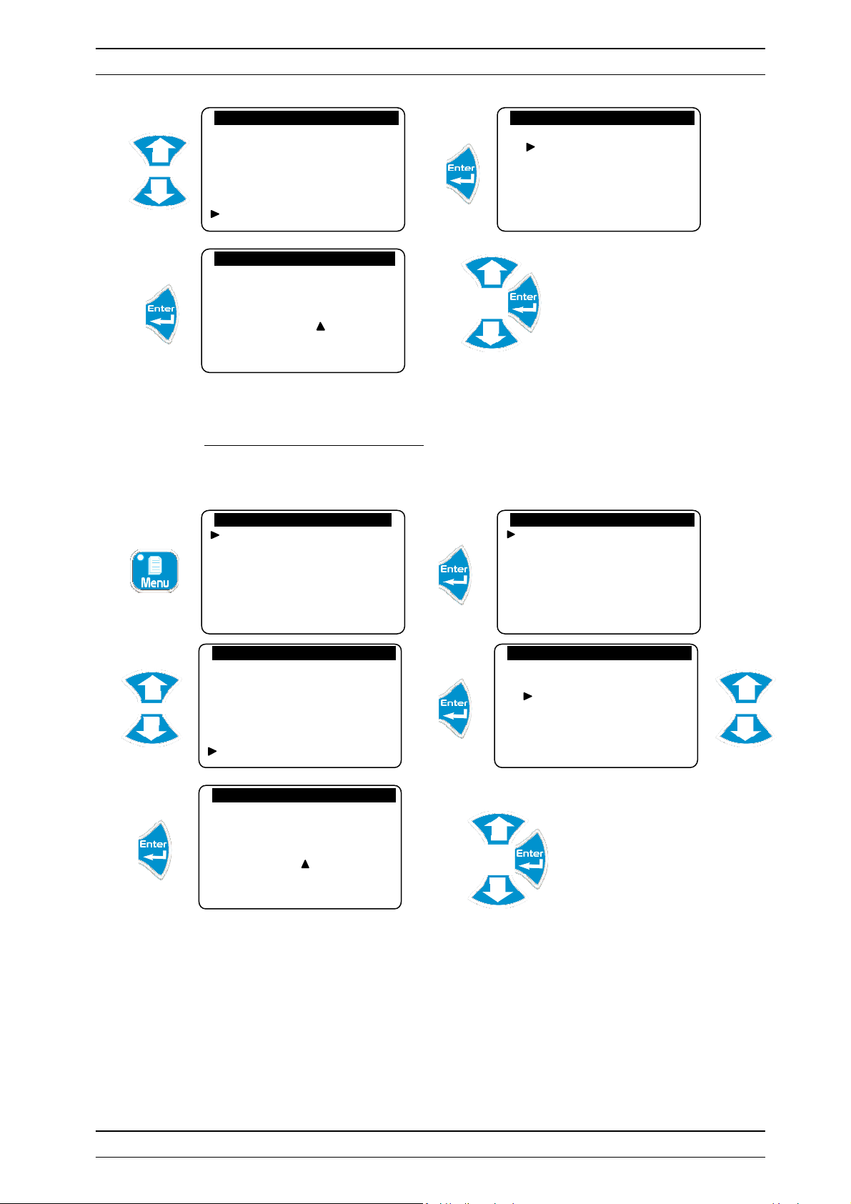
2) Choice of language
Technician level
Langue/Language/…
Set the time
Displays
Histories
Technician level
Langue/Language/…
Set the time
Displays
Histories
Langue/Language/…
Francais
English
Deutsch
Espanol
Italiano
Portuguese
Programming instructions SYCLOPE ODISEA
Technician level
Langue/Language/…
Set the time
Displays
Histories
®
Page 10

User menu Page 10/33
…….…......
User Menu
..… ......…
…….…......
User Menu
..…
......…
…
….…....
..User Menu
..…
......…
…….…......
User Menu
..…
......…
…….…......
User Menu
..…
......…
…… .…......
User Menu
..…..
....…
…….…......
User Menu
..…
......…
14 :44
ODISEA
27.5
°C pH Cl (ppm)
7.20
2.70
3) Time adjustment
Technician level
Langue/Language/…
Set the time
Displays
Histories
Technician level
Langue/Language/…
Set the time
Displays
Histories
Time … : 13H45 mn
Set the correct time
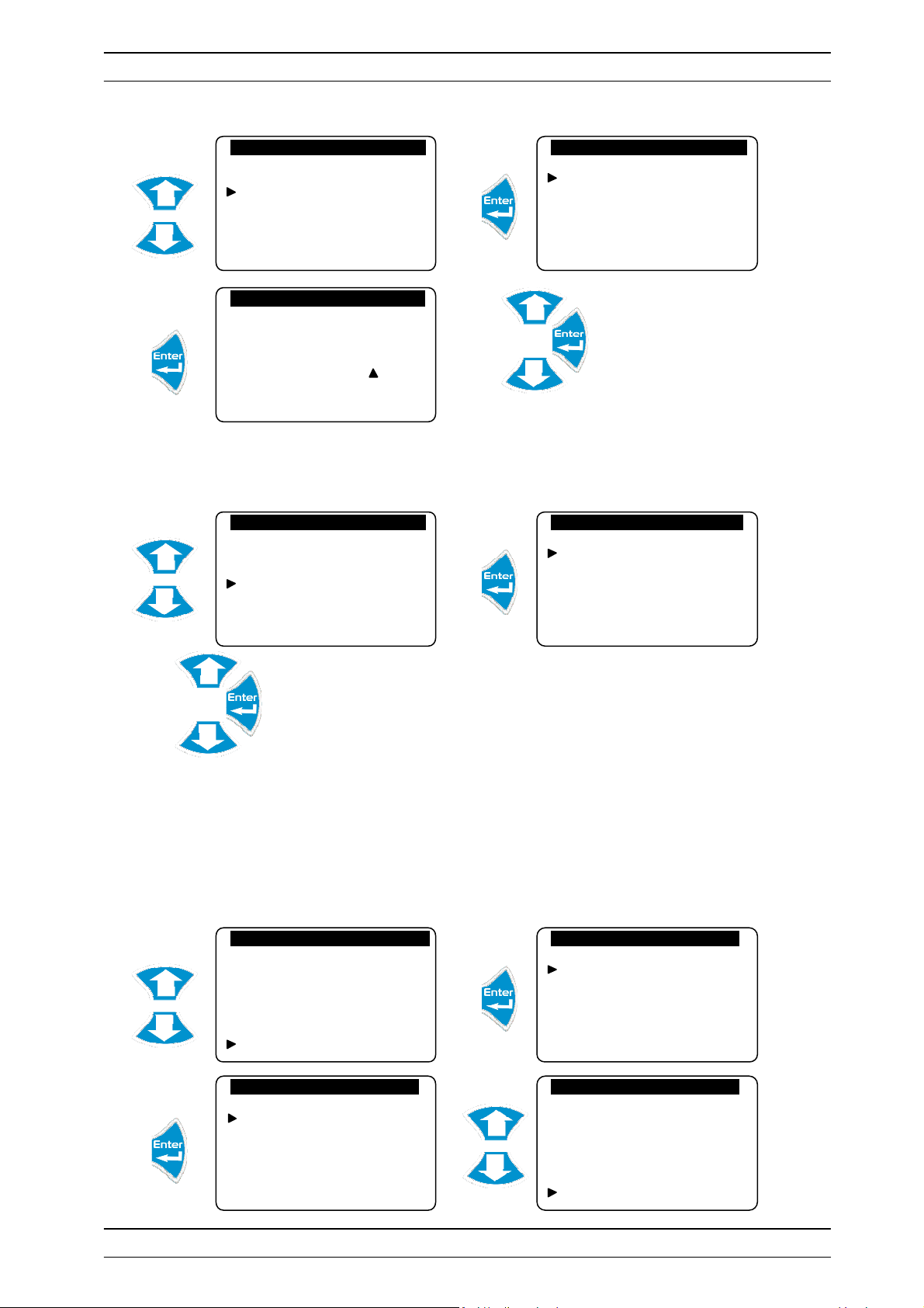
4) Display management
The user can decide to display the desired parameters all together or independently.
Technician level
Langue/Language/…
Set the time
Displays
Histories
Technician level
Langue/Language/…
Set the time
Displays
Histories
Choice of displays
pH
Chlorine
pH/Chlorine
Flowmeter
Technician level
Langue/Language/…
Set the time
Displays
Histories
->.<- 28.0 ->.<- 7.40 ->.<- 1.50
Programming instructions SYCLOPE ODISEA
®
Page 11

User menu Page 11/33
…….…......
User Menu
..… ......…
…….…......
User Menu
..… ......…
…….…....
.
Histories
Menu
..… ......…
…….…......
Histories
Menu
..…......…
…….…..
...Histories
Menu
..… ......…
…….…......
Histories
Menu
..…......…
…….…......
Histories Menu
..…......…
5) Histories
Traces and records the various events, alarms, measurements that take place with a frequency defined
by the user.
Technician level
Langue/Language/…
Set the time
Displays
Histories
Technician level
Langue/Language/…
Set the time
Displays
Histories
Events
Alarms
Data
Printer outputs
Reset histories
a) Events
Traces events that have occurred, such as activating the treatment, deactivating the treatment,
calibrating a parameter, etc …
Events
Alarms
Data
Printer outputs
Reset histories
Event Histories
23/02/09 9:42 am no.: 10
Switched on
23/02/09 10:35 am no.: 05
pH calibration
23/02/09 6:40 pm no.: 01
Switched off
Press “Up” and “Down” to scroll through the records.
See the table at the final page for the meaning of the event n°: XX
b) Alarms
Traces alarm excesses.
Events
Alarms
Data
Printer outputs
Reset histories
Alarm Histories
23/02/09 10:40 am no.: 08
Chlorine threshold alarm
23/02/09 12:30 pm no.: 07
pH threshold alarm
23/02/09 4:20 pm no.: 05
Chlorine threshold alarms
Press “Up” and “Down” to scroll through the records.
See the table at the final page for the meaning of the alarm n°: XX
Programming instructions SYCLOPE ODISEA
®
Page 12

User menu Page 12/33
…….…......
H
istories
Menu
..…......…
…
….….....
.
Histories Menu
..…
... ...…
…….…......
Histories
Menu
..…......…
…….…......
Histories Menu
…......…
…….…......
Histories
Menu
..…......…
…….…......
Histories Menu
..…......…
…….…......
Histories Menu
..…......…
c) Data
Traces measurements according to the defined time interval.
Events
Alarms
Data
Printer outputs
Reset histories
Data histories
Date : 23/02/09
°C pH mV Cl
15H27 30.9 7.34… 354 …2.58
15H37 30.4 7.26… 365 …2.50
15H47 30.9 7.18… 364 …2.45
15H57 30.9 7.00… 370 …2.65
Press “Up” and “Down” to scroll through the records.
d) Printer output
Allows you to print, in chronological order data collected.
Events
Alarms
Data
Printer outputs
Reset histories
Printer output
Printing in progress…
Press “Up” and “Down” to scroll through the records.
e) Reset Histories
Allows you to delete the selected families of entries.
Events
Alarms
Data
Printer outputs
Reset histories
Printer output
Reset events
Reset data
Reset alarms
Printer output
Reset events
Reset data
Reset alarms
Yes : Enter No : Esc
The events data are deleted.
Nothing is done.
► Do the same to delete the other types of records.
Programming instructions SYCLOPE ODISEA
®
Page 13

User menu Page 13/33
…….…......
Histories
Menu
..…......…
……
.…......
Technician Menu
..…......…
…….…......
Specialist Menu
.….. ....…
…….…......
Specialist Menu
.….... ..…
…….…......
Specialist Menu
.…..... .…
…….…......
Specialist Menu
.…..... .…
…….…......
Specialist Menu
.….... ..…
…….…. .....
Specialist Menu
.…......…
…….…......
Specialist Menu
.…......…
…….…......
User Menu
..…
......…
…….…
......
User Menu
..…
......…
6) Maintenance of the device
This function can be used to perform maintenance of the device. It is possible to simulate all the inputs
and outputs of the central unit in order to test their correct operation. This function can only be
performed once it has been activated in the Specialist Level.
To unblock the maintenance of the controller:
Events
Alarms
Data
Printer outputs
Reset histories
Specialist level
Technician code
System date
Setting(s)
Calibrations
General timers
Analogue outputs
Access code : 0 . . .
Enter the code 1234
Factory Code
Configurations
Initializations
Version: 3.01
Factory Code
Configurations
Initializations
Version: 3.01
Initializations
Factory reset
Modem
Maintenance management
Device number
Initializations
Factory reset
Modem
Maintenance management
Device number
Maintenance management
Activation…
Inactivation…
Initializations
Factory reset
Modem
Maintenance management
Device number
a) LEDs
Technician level
Langue/Language/…
Set the time
Displays
Histories
Technician level
Language
Set the time
Displays
Histories
Maintenance
Programming instructions SYCLOPE ODISEA
®
Page 14

User menu Page 14/33
…….…...
.. .System tests
..…
......…
…….…......
User Menu
..…
......…
…….…
......
User Menu
..…
......…
…….…....
..System tests
..…....
..…
…….….....
.System tests
..….
.....…
…….…......
User Menu
..…
......…
…….…
......
User Menu
..…
......…
…….…......
System tests
..…......…
…….…......
System tests
..….
.....…
LEDs
Relays
Analogue outputs
Printer
Check that the LEDs light up
b) Relays
Technician level
Langue/Language/…
Set the time
Displays
Histories
Technician level
Language
Set the time
Displays
Histories
Maintenance
LEDs
Relays
Analogue outputs
Printer
Relay test
Temperature
pH
Oxidiser
Flocculant
Auxiliary 1
Auxiliary 2
Check that the relay of output OUT1 is correctly activated
► Repeat this same process to test the other relays.
c) Analogue outputs
Technician level
Langue/Language/…
Set the time
Displays
Histories
Technician level
Language
Set the time
Displays
Histories
Maintenance
LEDs
Relays
Analogue outputs
Printer
Analogue outputs
Output IA1…: 00.0 mA
Output IA2…: 00.0 mA
Set values to simulate the analogue outputs
Programming instructions SYCLOPE ODISEA
®
Page 15
User menu Page 15/33
…….…......
User Menu
..…
......…
…….…
......
User Menu
..…
......…
…….…..
....
System tests
..…...
...…
…….…..
....
System tests
..…..
.
..…
d) Printer test
Technician level
Langue/Language/…
Set the time
Displays
Histories
Technician level
Language
Set the time
Displays
Histories
Maintenance
LEDs
Relays
Analogue outputs
Printer
Printer output
Printing in process
► Check that "Printer test" has printed correctly.
Programming instructions SYCLOPE ODISEA
®
Page 16

Technician Menu Page 16/33
…….…......
User Menu
..…
......…
…….…......
Technician Menu
..…......…
…
….….....
.
Spécialist Menu
..…
.....…
…….…......
Specialist Menu
.
…......…
…….…......
User Menu
..…
......…
…….…......
Technician Menu
..…......…
IV. Technician Menu
The Technician menu provides access to the modification of all the basic settings for the operation of
the treatment, such as:
Sensor calibration
Regulation settings
Technical alarm thresholds
System date
Analogue output scales
Operating timers
1) Specialist menu access
To access the Specialist level
Technician level
Langue/Language/…
Set the time
Displays
Histories
Specialist level
Technician code
System date
Setting(s)
Calibrations
General timers
Analogue outputs
Code d’accès : 0 . . .
Enter the code 1234
Factory Code
Configurations
Initialisations
Version: 3.01
2) Technician Code
To modify the existing Technician code or cancel the function for locking this level with a code.
a) Modification of the code
Allows the existing code to be changed.
Technician level
Langue/Language/…
Set the time
Displays
Histories
Specialist level
Technician code
System date
Setting(s)
Calibrations
General timers
Analogue outputs
®
Programming instructions SYCLOPE ODISEA
Page 17

Technician Menu Page 17/33
…….…......
Technician Menu
..…......…
…….….....
Technician Menu
..… ......…
…….…......
User Menu
..…
......…
…….…......
Technician Menu
..….
.....…
…….…......
Technician Menu
..…......…
…….….....
Technician Menu
..… ......…
…….…......
User Menu
..…
......…
…….…......
Technician Menu
..…......…
…….…......
Technician Menu
..…......…
…….…......
Technician Menu
..…......…
Specialist level
Technician code
System date
Setting(s)
Calibrations
General timers
Analogue outputs
Enter your code to control access to this level
b) Cancellation of the code
Cancels the function to lock this level by a code
Technician level
Langue/Language/…
Set the time
Displays
Histories
Specialist level
Technician code
System date
Setting(s)
Calibrations
General timers
Analogue outputs
Enter the code 0000 to cancel access control for this level.
New code : 0 . . .
Specialist level
Technician code
System date
Setting(s)
Calibrations
General timers
Analogue outputs
New code : 0 . . .
3) Adjustment of the system date
Allows user to adjust set or adjust date. The system date must be configured correctly in order to
manage the operating timers.
Technician level
Langue/Language/…
Set the time
Displays
Histories
Specialist level
Technician code
System date
Setting(s)
Calibrations
General timers
Analogue outputs
Specialist level
Technician code
System date
Setting(s)
Calibrations
General timers
Analogue outputs
System date
Year : 09 Month: 02
Date: 10 Day: 3
®
Programming instructions SYCLOPE ODISEA
Page 18

Technician Menu Page 18/33
…….…......
User Menu
..…
......…
…….…......
Technician Menu
..…......…
…….…......
Technician Menu
..…....
..…
…….…......
Technician Menu
..…......…
…
….….....
.
Technician Menu
..…
.....…
…….…......
User Menu
..…
......…
…….…......
Technician Menu
..…......…
…….…......
Technician Menu
..…......…
…….…......
Technician Menu
..…......…
Adjust the system date. For example, the programmed date is Wednesday 10
February 2009
4) Programming a setting point
Allows you to program the setting point for controlling the various parameters.
Technician level
Langue/Language/…
Set the time
Displays
Histories
Specialist level
Technician code
System date
Setting(s)
Calibrations
General timers
Analogue outputs
Specialist level
Technician code
System date
Setting(s)
Calibrations
General timers
Analogue outputs
General settings
Temperature
pH
Rédox
Chlorine
Setting (°C) : 28.0
Temp. regulation
Adjust the setting point
► Repeat this process to adjust all the other setting points.
5) Calibration of a measurement parameter
In this menu, you can perform three operations involving the measurements of a sensor.
Standard (Gain): to calibrate the sensor with the standard value measured
Zero: to set a sensor to zero when required
Delete: to delete the calibration and zero registered and return to the factory value
Technician level
Langue/Language/…
Set the time
Displays
Histories
Specialist level
Technician code
System date
Setting(s)
Calibrations
General timers
Analogue outputs
Specialist level
Technician code
System date
Setting(s)
Calibrations
General timers
Analogue outputs
Programming instructions SYCLOPE ODISEA
General settings
Temperature
pH
Rédox
Chlorine
®
Page 19

Technician Menu Page 19/33
…….…......
Technician Menu
..…......…
…….…......
Technician Menu
..…......…
…….…......
Technician Menu
..…......…
…….…......
Technician Menu
..…......…
…….…......
Technician Menu
..….....
.…
…….…......
Technician Menu
..…......…
…….…......
Technician Menu
..…......…
…….…......
Technician Menu
..…......…
c) To set zero (pH=7)
General settings
Temperature
pH
Rédox
Chlorine
pH calibration
pH=7.00
Gain
Factory values
Calibrate the zero by entering the desired value
pH calibration
pH=7.00
Gain
Factory values
pH calibration
Standard…: 7.01 pH
d) To perform the gain
pH calibration
pH=7.00
Gain
Factory values
pH calibration
Standard…: 7.31 pH
Calibrate the gain by entering the desired value
e) To delete the recorded calibration
pH calibration
pH=7.00
Gain
Factory values
pH calibration
pH=7.00
Gain
Factory values
Calib. in process…
This process allows you to return to the factory value, which is exempt from calibration.
Programming instructions SYCLOPE ODISEA
®
Page 20

Technician Menu Page 20/33
…….…......
User Menu
..…
......…
…….….....
.
Technician Menu
..…......…
…….…......
Technician Menu
..…......…
…….…......
Technician Menu
..…......…
…….…....
.
Technician Menu
..…......…
…….…...
..
Technician Menu
..…......…
…
..........
Technician
Menu
.....
...>.
............
.
Technician
Menu
.........
.....
…….…..
Technician Menu
..… ......…
J F M A M J J A S O N D
6) Programming of the general timers
Allows programming the various cyclic functions of the controller.
Technician level
Langue/Language/…
Set the time
Displays
Histories
Specialist level
Technician code
System date
Setting(s)
Calibrations
General timers
Analogue outputs
Specialist level
Technician code
System date
Setting(s)
Calibrations
General timers
Analogue outputs
General timers
Filtering
Flocculant
Printing
Storage rate
a) Filtering timer
Allows you to control the start-up of the re-circulating motor according to several time intervals,
depending on the week or even depending on the season.
For this function to be performed, it is necessary first to activate it in the configuration management of
the specialist level (see Chapter VII Paragraph 2: Filter timers).
General timers
Filtering
Flocculant
Printing
Storage rate
Filter cycles
Seasons
Weeks
Timers
Definition of the operating seasons
It is possible to program the controller to operate in the winter, summer or automatic winter/summer.
For this, it is necessary first of all to define the seasons in automatic mode.
Circulating cycles
Seasons
Weeks
Timers
Cycles of the seasons
Automatic
Summer
Winter
Summer
Cycles of the seasons
Adjust the summer/winter
cursors to define the start of
the seasons.
Winter
Programming instructions SYCLOPE ODISEA
®
Page 21

Technician Menu Page 21/33
…….
.....
Technician Menu
..…....
..…
…….….
...
Technician Menu
..…. .....…
…
….….....
.
Menu Technicien
..…
......…
…….…......
Technician Menu
..…......…
……....
Timers
–
Summer
–
....….....
…
► Select automatic mode for filtering to operate in winter and summer mode according to the
programmed seasons.
► Select "Summer" mode for filtering to operate only in summer according to the
programmed cycle of seasons.
► Select "Winter" mode for filtering to operate only in winter according to the programmed
cycle of seasons.
Definition of the number of filtering weeks
It is possible to define the filtering cycles over several weeks with different time intervals. For example,
a filtering cycle can take place over 8 weeks with different time intervals for each week.
Filter cycles
Seasons
Weeks
Timers
Week cycles
Current week: 1
Duration (weeks): 8
Define the number of filtering weeks
Definition of filtering time intervals by weeks
This is a question of defining the operating time intervals according to the season, week and days of
the week. It is possible to set up to 8 timers.
Cycles filtration
Saisons
Semaines
Timers
Season cycles
Summer
Winter
Reset timers
On: 9:00 am Off: 6:00 pm
M T W T F S S S:1
Set timer 1
Set the operating time interval
and the days of the week on
which this interval is applicable.
In the example above, timer 1 is set to activate the filtering from 9 am to 6 pm on Monday, Tuesday,
Wednesday, Thursday and Friday of week 1.
► Follow this same process to set all the desired timers for the summer season.
► Follow this same process to set all the desired timers for the winter season.
► Activate the "Reset timers" line to delete all the recorded timers.
To control the filter motor, the user must program an available relay of the motor in order to
activate the motor (see Chapter VII Paragraph 2: Prog. relays).
Programming instructions SYCLOPE ODISEA
®
Page 22

Technician Menu Page 22/33
…….…...
Technician Menu
..
…......…
…….…...
.
Technician Menu
..….. ....…
…
….…...
.
Menu Technicien
..…
. .....…
…….….
...
Technician Menu
..… ......…
…….…
....
Technician Menu
..… ......…
…….…...
.
Technician Menu
..…. .....…
…….….
...
Technician Menu
.. …
......…
b) Flocculant management
Allows management of flocculant injection in various modes.
For this function to be performed, it is necessary first to activate it in the configuration management
of the specialist level (see Chapter VII Paragraph 2: Flocculant).
General timers
Filtering
Flocculant
Printing
Storage rate
Flocculant op.
Continuous
Timed
Flow meter
In continuous mode :
Fct du floculant
Continu
Temporisé
Débitmètre
Continuous flocculant injection
In timed mode
Flocculant op.
Continuous
Timed
Flow meter
Flocculant op.
Continuous
Timed
Flow meter
Ratio…(sec/min): 020
Program the flocculant injection ratio
In the example above, the controller will inject flocculant for 20 seconds and stop injecting for 40
seconds before resuming the cycle.
In flow meter mode
Flocculant op.
Continuous
Timed
Flow meter
Flocculant op.
Continuous
Timed
Flow meter
No. of pulses : 050
Set the number of pulses from the flow meter contact (to be connected to the
meter input WM) from which the central unit will inject the flocculant.
Programming instructions SYCLOPE ODISEA
®
Page 23

Technician Menu Page 23/33
…….…......
User Menu
..… ......…
…….
.....
Technician Menu
.. …......…
…….…....
Technician Menu
..…. .....…
……
......
Technician Menu
..… ......…
…….
.....
Technician Menu
..…. .....…
……......
Technician Menu
..…. .....…
In flow meter mode, the user must first activate the meter input in the configuration
management of the specialist level (see Chapter VII Paragraph 2: Meter input)
To manage the flocculant, the user must program an available relay of the central unit in
order to activate the flocculant pump (see Chapter VII Paragraph 2: Prog. relays).
c) Printing
Allows you to define the printer printing rate.
General timers
Filtering
Flocculant
Printing
Storage rate
Printer output
Printing delay: 000 min
Adjust the printing rate
d) Recording rate
Allows you to define the log recording rate.
General timers
Filtering
Flocculant
Printing
Storage rate
Rate……..: 030 min
Adjust the recording rate
7) Programming the scale of analogue outputs
Allows you to define the scales (bottom and top) of the analogue outputs.
Technician level
Langue/Language/…
Set the time
Displays
Histories
Specialist level
Technician code
System date
Setting(s)
Calibrations
General timers
Analogue outputs
Storage rate
Programming instructions SYCLOPE ODISEA
®
Page 24
Technician Menu Page 24/33
…….…
....
Technician Menu
..… ......…
…….…
..
Technician Menu
..…... ...…
…
….…..
Technician Menu
..…
. .....…
…….…......
User Menu
..…
......…
…….….
...
Technic
ian Menu
.. …......…
…….…..
..
Technician Menu
..…... ...…
…….…
....
Technician Menu
..….. .
...…
…….….
...Technician Menu
..… ......…
Specialist level
Technician code
System date
Setting(s)
Calibrations
General timers
Analogue outputs
Analogue outputs
pH
Chlorine
Basse…(4 mA) : 06.50
Haute…(20 mA) : 8.50
Analog. Output IA1
pH
Adjust the scale of the
analogue output.
► Follow this same process to adjust the other analogue outputs.
8) Programming the alarm thresholds
Allows you to define the alarm thresholds (top and bottom) of the various measurement parameters.
Technician level
Langue/Language/…
Set the time
Displays
Histories
Specialist level
Technician code
System date
Setting(s)
Calibrations
General timers
Analogue outputs
Technician code
System date
Setting(s)
Calibrations
General timers
Analogue outputs
Alarms
Alarm thresholds
Temperature
pH
Chlorine
Min.….…(pH): 6.80
Max.……(pH): 7.90
Alarm thresholds
Adjust the alarm thresholds
► Follow this same process to adjust the other alarm thresholds.
Programming instructions SYCLOPE ODISEA
®
Page 25

Specialist menu Page 25/33
…….…....
..User Menu
..…
......…
…
….…
....
Technician Menu
..…. .....…
…….…....
Specialist Menu
..…. .....…
…….…..
..
Specialist Menu
.…....
..…
…….…....
Specialist Menu
..….. ....…
…….…..
..Specialist Menu
.…..
....…
V. Specialist Menu
The Specialist menu provides access to complete modifications of the machine's configuration:
Activation of the various functions (timers, flocculant, meter, etc.)
Adjustment operation
Relay assignment
Analogue output assignment
Initializations (factory reset, maintenance management, etc.)
To access the Specialist level
Technician level
Langue/Language/…
Set the time
Displays
Histories
Specialist level
Technician code
System date
Setting(s)
Calibrations
General timers
Analogue outputs
Access code: 0 . . .
Enter the code 1234
Factory Code
Configurations
Initializations
Version: 3.01
1) Factory code
To modify the existing Factory code or cancel the function for locking this level with a code.
a) Modification of the code
Allows you the existing code to be changed.
Factory Code
Configurations
Initializations
Version: 3.01
New code : 0 . . .
Enter your new code to access specialist level
®
Programming instructions SYCLOPE ODISEA
Page 26

Specialist menu Page 26/33
…….…....
Specialist Menu
..…. .....…
…….…..
.
Specialist Menu
.….
.....…
…….…..
.
Specialist Menu
.…. ..
...…
…….…....
.
Specialist Menu
.….
.....…
…….…...
.
Specialist Menu
.….
.....…
…….…..
..
Specialist Menu
.…..
....…
…….…....
.
Specialist Menu
.….
.....…
…….…... .
Specialist
Menu
.…. .....…
b) Cancellation of the code
Cancels the function to lock this level by a code.
Factory Code
Configurations
Initializations
Version: 3.01
New code : 0 . . .
Enter the code 0000 to cancel access control for this level.
2) Configurations
Allows you to change the machine configuration.
Factory Code
Configurations
Initializations
Version: 3.01
Configurations
Filter timers
Flocculant
Meter input
Flow switch
Adjustment operation
Prog. relays
a) Timers filtration
Allows you to activate the filter timer function
Configurations
Filter timers
Flocculant
Meter input
Flow switch
Adjustment operation
Prog. relays
The function to control the filtering motor is now activated.
b) Flocculant
Allows you to activate the flocculant management function.
Configurations
Filter timers
Flocculant
Meter input
Flow switch
Adjustment operation
Prog. relays
Flocculant management is now active.
Filter control
Activation…
Inactivation…
Floculant control
Activation…
Inactivation…
Programming instructions SYCLOPE ODISEA
®
Page 27

Specialist menu Page 27/33
…….…....
.
Specialist Menu
.….
.....…
…….…......
Specialist Menu
.…... ...…
…….…....
.
Specialist Menu
.….
.....…
…….…......
Specialist Menu
.… ......…
…….…....
.
Specialist Menu
.….
.....…
…….…......
Specialist Menu
.… ......…
…….…......
Specialist Menu
.…. .....…
…….…......
Specialist Menu
.….
.....…
…
….….....
.
Spécialist Menu
.…
......…
c) Metering input
Enables activation of the meter input (CPT)
Configurations
Filter timers
Flocculant
Meter input
Flow switch
Adjustment operation
Prog. relays
Flow meter control
Activation…
Inactivation…
The metering function is now active.
d) Flow switch (flow detector)
Permet l’activation de l’entrée de détection de débit (DEB)
Configurations
Filter timers
Flocculant
Meter input
Flow switch
Adjustment operation
Prog. relays
Flow switch control
Activation…
Inactivation…
The flow-detection function is now active.
e) Programming controls
Allows you to change the adjustment of each control parameter.
Configurations
Filter timers
Flocculant
Meter input
Flow switch
Prog. controls
Prog. relays
Adjustment of the proportional band
Programming controls
Proportional band(s)
Cycle time
pH+/pH- adjustment
Régulation Temp.
Prop. Band (Xp) : 010
► Follow this same process to adjust the other parameters.
Programming controls
Proportional band(s)
Cycle time
pH+/pH- adjustment
Programming controls
Temperature
pH
Redox (ORP)
Chlorine
Adjust the value of the
proportional band
Programming instructions SYCLOPE ODISEA
®
Page 28
Specialist menu Page 28/33
…….…......
Specialist Menu
.…. .....…
…….…......
Specialist Menu
.…. .....…
…
….….....
.
Menu Spécialiste
.…
......…
…….…......
Specialist Menu
.…. .....…
…….…......
Specialist Menu
.….. ....…
…….…....
.
Specialist Menu
.….
.....…
…….…......
Specialist Menu
.…......…
…….…......
Specialist Menu
.…......…
…….…......
Specialist Menu
.…......…
Adjustment of the cycle time
Programming controls
Proportional band(s)
Cycle time
pH+/pH- adjustment
Programming controls
Temperature
pH
Redox (ORP)
Chlorine
Temp. adjustment
Cycle time ………..: 120
Adjust the value of the cycle
time.
► Follow this same process to adjust the other parameters.
Definition of the direction of pH adjustment
Programming controls
Proportional band(s)
Cycle time
pH+/pH- adjustment
pH adjustment direction
pH adjustment –
pH adjustment +
Choose the required adjustment direction.
f) Relay assignment
Allows you to assign the available relays to manage other functions such as:
General alarms
Measurement alarms
Filter timers
Reverse pH direction
Configurations
Filter timers
Flocculant
Meter input
Flow switch
Prog. controls
Prog. relays
Relay assignment
Relay 4
Imp1 relay
Imp2 relay
Relay 4 powered
None
Filter timers
Reverse pH adjustment
General alarms
Temp. alarms
pH alarms
Relay 4 powered
General alarms
Temp. alarms
pH alarms
Redox alarms
Chlorine alarms
Flocculant
Programming instructions SYCLOPE ODISEA
®
Page 29

Specialist menu Page 29/33
…….…......
Specialist Menu
.…......…
…….…......
Spec
ialist Menu
.…......…
…….…......
Specialist Menu
.…......…
…….…......
Specialist Menu
.…......…
…….…......
Specialist Menu
.…......…
…….…......
Specialist Menu
.…......…
…….….....
Specialist Menu
.…. .....…
…….….....
Specialist Menu
. … ......…
► Select "None" to not use the selected relay
► Select “Filter timers” to control the filter motor
► Select “Reverse pH adjustment” to control the injection of pH+ (if you chose pH- in the
relay configuration)
► Select “General alarms” to activate an alarm relay
► Select “pH alarms” to activate an alarm relay
► Select “Chlorine alarms” to activate an alarm relay
► Select “Flocculant” to control the injection of flocculant.
g) Definition of the analogue output mode
Allows you to configure the analogue outputs as an adjustment output or a data transfer.
Configurations
Flocculant
Meter input
Flow switch
Adjustment operation
Prog. relays
Analogue outputs
Analogue outputs
Output IA1
Output IA2
Analogue outputs
None
Regulation
Transfer
Analogue outputs. IA1
None
Regulation
Transfer
► Select "None" to not use the selected analogue output
► Select “Adjustment” to control an injection pump
► Select “Data transfer” to forward the current to a central unit
Analogue output IA1
Temperature
pH- regulation
pH+ regulation
Redox
Chlorine
Analogue output IA1
0…20 mA
4…20 mA
20…0 mA
20…4 mA
► Follow this same process to program the other analogue outputs
3) Initializations
Allows you to reset the machine, activate the modem, define the case number for communication and
activate machine maintenance.
Factory Code
Configurations
Initializations
Version: 3.01
Initializations
Factory reset
Modem
Maintenance management
Device number
®
Programming instructions SYCLOPE ODISEA
Page 30

Specialist menu Page 30/33
…….….....
Specialist Menu
. … ......…
…
….…......
Specialist Menu
.…... ...…
…….….....
Specialist Menu
. … ......…
…….…......
Specialist M
enu
.…...... …
…….….....
Specialist Menu
. … ......…
…......... .
Specialist
Menu
........ >. …
…….….....
Specialist Menu
. … ......…
…….…......
Specialist Menu
.….... ..…
a) Factory reset
Allows you to return the central unit to its basic factory configuration. All settings made by the user will
then be deleted.
Initializations
Factory reset
Modem
Maintenance management
Device number
Reset Memory?
If yes, Enter !
The reset has been performed !
b) Modem activation
Allows you to activate modem communication.
Initializations
Factory reset
Modem
Maintenance management
Device number
Modem
Activation…
Deactivation…
Modem communication is now active.
c) Maintenance management activation
Allows you to activate the controller maintenance management.
Initializations
Factory reset
Modem
Maintenance management
Device number
Maintenance management
Activation…
Inactivation…
Maintenance management is now active.
d) Device number
Allows you to identify the device unit in order to establish communication.
Initializations
Factory reset
Modem
Maintenance management
Device number
Number: 0 0 0
Configure the device unit identifier number
Identification
Programming instructions SYCLOPE ODISEA
®
Page 31

Table of events and alarms histories Page 31/33
VI. Table of events and alarms histories
Table of events :
n° Message displayed Meaning
00 Service on Starting controls (Start key)
01 Service off Stop controls (Stop key)
02 Stop from ext. entry External break for controls
03 Stop from flow switch Flow switch break for controls (No water circulation)
04 Temperature Calibration Calibration of the temperature sensor
05 Calibration pH Calibration of the pH sensor
06 Redox (ORP) calibration Calibration of the Redox (ORP) sensor
07 Chlorine calibration Calibration of the Chlorine sensor
08 Bromine calibration Calibration of the Bromine sensor
09 Flow switch calibration Calibration of the flow switch sensor
10 Powering Powering of the controller
Table of alarms :
n° Message displayed Meaning
00 Temperature default Measuring in error or sensor missing
01 pH sensor default Measuring in error or sensor missing
02 ORP sensor default Measuring in error or sensor missing
03 Chlorine sensor default Measuring in error or sensor missing
04 Bromine sensor default Measuring in error or sensor missing
05 Alarm threshold Temperature Abroad thresholds set
06 Alarm threshold pH Abroad thresholds set
07 Alarm threshold Redox (ORP) Abroad thresholds set
08 Alarm threshold Chlorine Abroad thresholds set
09 Alarm threshold Bromine Abroad thresholds set
Programming instructions SYCLOPE ODISEA
®
Page 32

Table of events and alarms histories Page 32/33
Programming instructions SYCLOPE ODISEA
®
Page 33

SYCLOPE Electronique S.A.S.
Z.I. Aéropole pyrénées
Rue du Bruscos
64 230 SAUVAGNON - France –
Tel : (33) 05 59 33 70 36
Fax : (33) 05 59 33 70 37
Email : syclope@syclope.fr
Internet : http://www.syclope.fr
© 2008 by SYCLOPE Electronique S.A.S.
Programming instructions SYCLOPE ODISEA
®
 Loading...