

Page 1
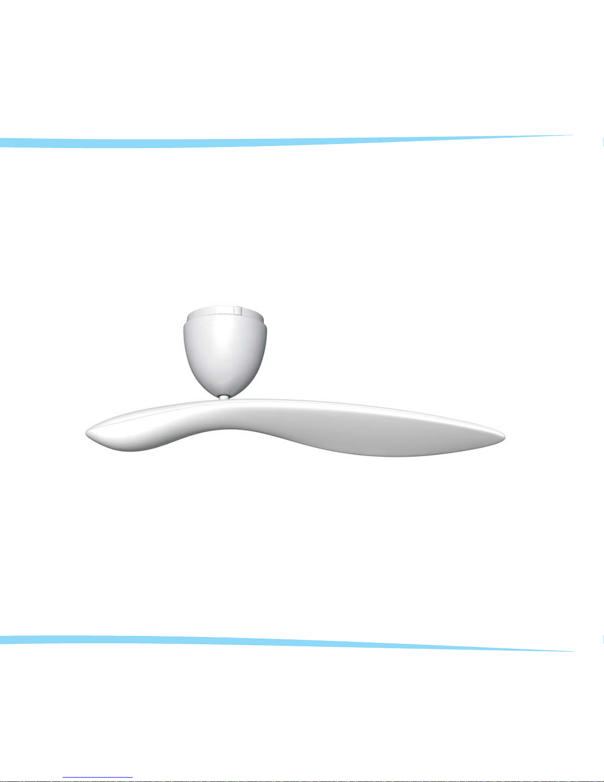
Sycamore Ceiling Fan
nature + technology
Instruction Manual
INSTALLATION - OPERATION - MAINTENANCE - WARRANTY
TM
Page 2

Introduction ................................................
Important Safety Precautions . . . . ................................
UnpackingYourSycamoreFan ...................................
Preparing Ceiling, Installing Hanger Bracket
and Making Hanger Bracket Electrical Connections ....................
Preparing and Installing Fan Motor Assembly
and Making Fan Motor Assembly Electrical Connections ................
Installing Wall Controller
and Making Wall Controller Electrical Connections . ...................
Wall Controller Installation Wiring Diagram . . . .......................
Setting Accessory Remote Control Codes . . . .......................
Installing Accessory Remote Control Receiver
and Making Remote Control Receiver Electrical Connections . . ...........
Accessory Remote Control Installation Diagram . . . ...................
Preparing and Installing Fan Motor Housing . . .......................
Preparing and Installing Fan Blade . . . . . . . . .......................
Operating Your Sycamore Fan . . . . . . . . . . . . .......................
CareandCleaning...........................................
Trouble Shooting . . ..........................................
GeneralInformationonCeilingFans ..............................
TechnicalSpecifications .......................................
Warranty..................................................
Page 1
Page 2
Page 4
Page 6
Page 10
Page 14
Page 17
Page 18
Page 21
Page 25
Page 26
Page 29
Page 33
Page 35
Page 36
Page 37
Page 38
Page 39
Table of Contents
0
IF THERE ARE ANY PROBLEMS DURING INSTALLATION OF THE FAN, THE INSTALLER MUST CONTACT THE
HUNTER PACIFICINTERNATIONAL WARRANTY LINE . TEL: 1300 360 280BEFORE LEAVING THE WORK SITE
Page 3
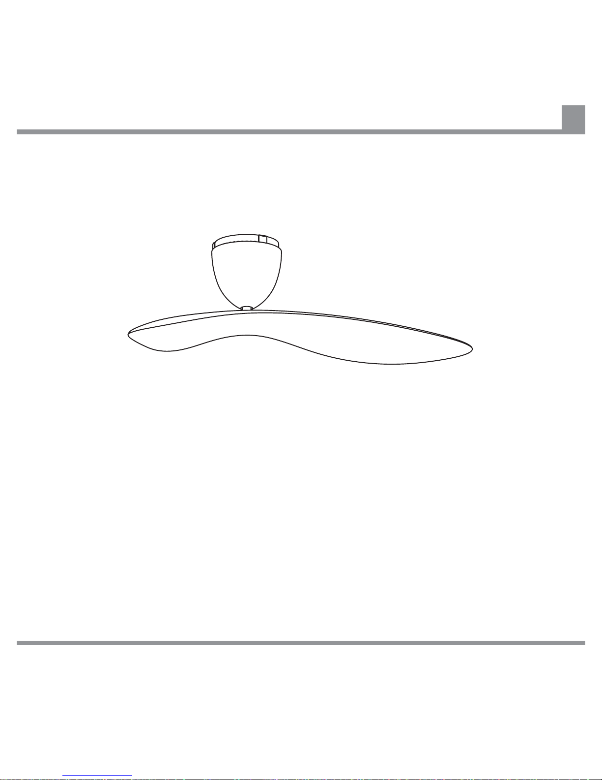
Thank you for choosing a Sycamore™ Ceiling Fan. You have chosen the best! We are confident that your
new ceiling fan will provide many years of service and enjoyment.
Please read and follow these instructions carefully, and be mindful of all warnings shown throughout this
manual.
GENERAL PRECAUTIONS
This fan must be installed by a licensed and qualified electrician according to local authority
regulations.
Be cautious! Read all instructions and safety information, and review the accompanying assembly
diagrams before installing your new fan.
Close supervision is necessary when the product is used by children or invalid people. Do not allow
children to use it as a toy.
Introduction
1
IF THERE ARE ANY PROBLEMS DURING INSTALLATION OF THE FAN, THE INSTALLER MUST CONTACT THE
HUNTER PACIFICINTERNATIONAL WARRANTY LINE . TEL: 1300 360 280BEFORE LEAVING THE WORK SITE
Page 4

Important Safety Precautions
2
LOCATION AND INSTALLATION REQUIREMENTS FOR YOUR FAN
MECHANICAL ISSUES
To provide adequate clearance from the floor the lowest point on the fan blade must be at least 2.1m (7’)
from the floor.
Note: For a fan mounted directly to the ceiling, the lowest point of the fan blade is approximately 365mm
(14 ½”) below the ceiling.
Make sure that the chosen location of the fan will not allow the rotating fan blade to come into contact with
any object.
Ensure ceiling joists are sound and of adequate size and strength to support a 35Kg (77lb) load.
To reduce the risk of fire, electrical shock or personal injury, ensure that the fan mounting bracket is
supported directly from the building structure. DO NOT mount to an outlet box.
The mounting bracket must be firmly screwed to a load bearing structure e.g. a concrete ceiling, steel
structure or timber frame. If a timber frame is to be added it must be securely nailed or screwed between
two beams.
Do not remove the fan from the ceiling after installation.
Do not attach the Fan Blade before the Fan Motor Housing is installed and secured. To protect the finish,
the Fan Blade and the Fan Motor Housing should be kept in their cartons until ready to be installed.
After the fan is completely installed, check to make sure that all connections are secure to prevent the fan
from falling and/or causing damage or injury.
To reduce the risk of personal injury, do not bend or damage the motor Drive Shaft or Fan Blade when
handling or installing them.
IF THERE ARE ANY PROBLEMS DURING INSTALLATION OF THE FAN, THE INSTALLER MUST CONTACT THE
HUNTER PACIFICINTERNATIONAL WARRANTY LINE . TEL: 1300 360 280BEFORE LEAVING THE WORK SITE
Page 5

Important Safety Precautions
3
ELECTRICAL ISSUES
Do not attempt to control the operation of this fan from any wall controller that is not approved
by Hunter Pacific International Pty Limited for use with this fan. DO NOT use a solid state wall
controller. The use of an unapproved wall controller voids the warranty.
NOTE
The fan and hanger bracket must be earthed.
The fan can be used in conjunction with some home automation systems. For further information please
contact Hunter Pacific International Pty Limited.
To avoid possible electric shock during installation, be sure electricity is turned off at the main power box
before commencing work. Disconnect power by removing fuse or turning off circuit breaker before
installing the fan. Ensure all spliced connections are adequately insulated.
Nothing in this manual is intended to instruct or assist untrained or unqualified persons to install this
product. Additionally, it is the responsibility of the installer and user to apply common sense and care at all
times.
IF THERE ARE ANY PROBLEMS DURING INSTALLATION OF THE FAN, THE INSTALLER MUST CONTACT THE
HUNTER PACIFICINTERNATIONAL WARRANTY LINE . TEL: 1300 360 280BEFORE LEAVING THE WORK SITE
Page 6
Unpacking your Sycamore Fan
4
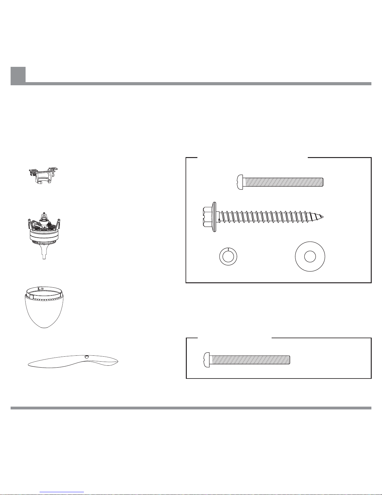
Unpack your fan and check the contents. You should have two cartons - a Motor Carton and a Blade
Carton. Do not discard the cartons. If warranty replacement or repair is ever necessary, the fan should be
returned in the original packaging.
Examine all parts. You should have the following:
Fan Motor Assembly
x 1 unit
Hanger Bracket
x 1 unit
Fan Motor Housing
x 1 unit
Fan Blade
x 1 unit
Screw
x 2 units (1 + 1 Spare)
Washer
x 2 units
Washer
x 2 units
Screw
x 2 units
Screw
x 2 units
Hanger Bracket Hardware
IF THERE ARE ANY PROBLEMS DURING INSTALLATION OF THE FAN, THE INSTALLER MUST CONTACT THE
HUNTER PACIFICINTERNATIONAL WARRANTY LINE . TEL: 1300 360 280BEFORE LEAVING THE WORK SITE
Blade Hardware
Page 7
Unpacking your Sycamore Fan
5
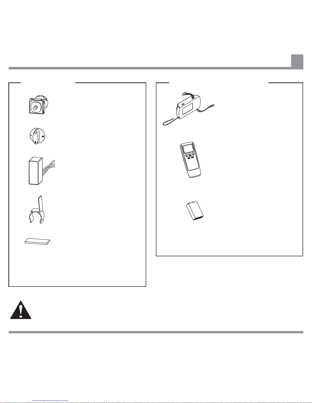
Remote Control
Transmitter
x 1 unit
Remote Control Receiver
x 1 unit
Remote Control (Accessory)
Battery
x1 unit
Wall Controller
Speed Controller
x 1 unit
Rotary Speed Switch
x 1 unit
Capacitor
x 1 unit
Clip
x 1 unit
Double Sided Tape
x 1 unit
IF THERE ARE ANY PROBLEMS DURING INSTALLATION OF THE FAN, THE INSTALLER MUST CONTACT THE
HUNTER PACIFICINTERNATIONAL WARRANTY LINE . TEL: 1300 360 280BEFORE LEAVING THE WORK SITE
Warning: Do not attempt to control the operation of this fan from any wall controller that is not
approved by Hunter Pacific International Pty. Limited for use with this fan. Do not use a solid
state wall controller. The use of an unapproved wall controller voids the warranty.
Note:
Back Plate, Face Plate and ON/OFF switch are
not supplied with fan.
Note:
Remote Control Transmitter may vary from one
shown.
Page 8
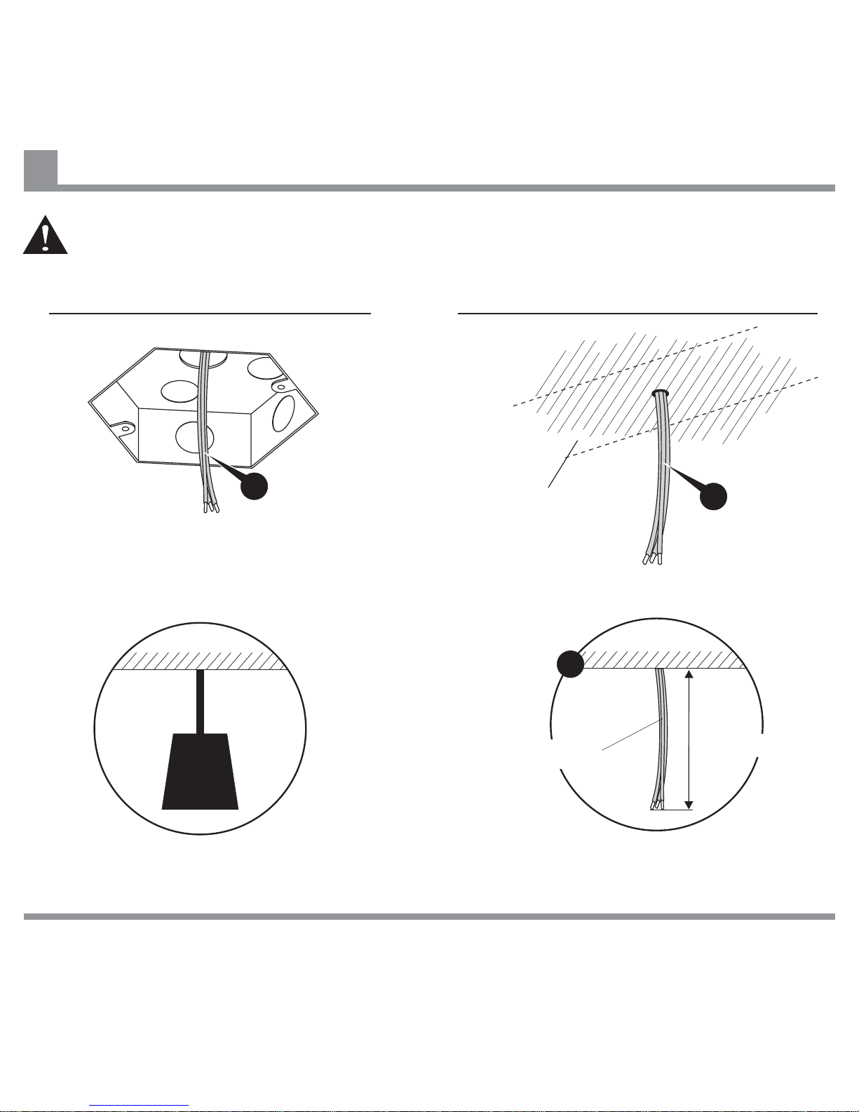
Ceiling
Supply Wiring
Installation using Ceiling Mounting Box Installation directly mounted to Ceiling Joist
Check that the mounting location is of
adequate strength to support the fan.
Ensure the Supply Wiring is of
sufficient length.
approx.
75mm (3”)
Before commencing installation, turn off electricity supply at the main power box.
Disconnect power by removing fuse or turning off circuit breaker before commencing work.
Checking Ceiling Condition and Preparing for Fan Installation
6
IF THERE ARE ANY PROBLEMS DURING INSTALLATION OF THE FAN, THE INSTALLER MUST CONTACT THE
HUNTER PACIFICINTERNATIONAL WARRANTY LINE . TEL: 1300 360 280BEFORE LEAVING THE WORK SITE
A
Ceiling Joist
behind ceiling
A
Ceiling
35KG
A
Page 9
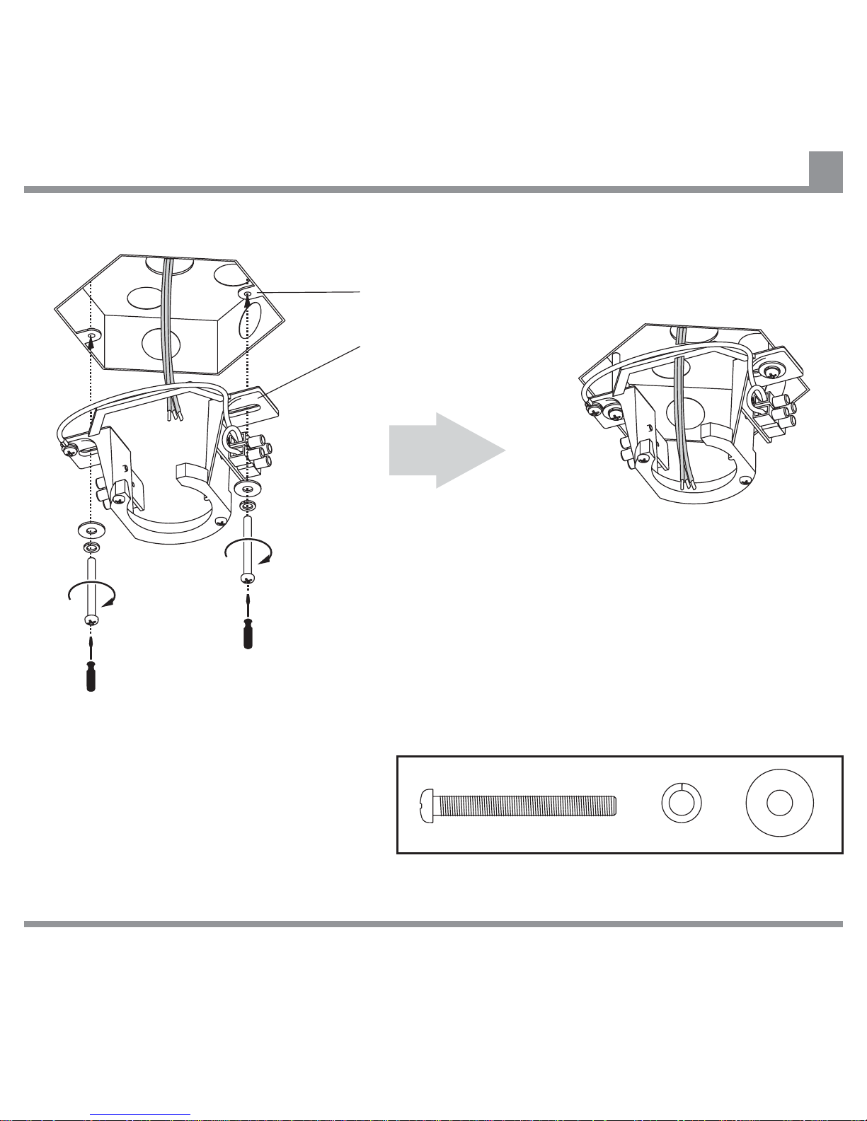
Hanger Bracket
Embedded Mounting Box
Secure Hanger Bracket to Mounting Box using
screws and washers provided. Ensure screws are
securely tightened.
Note:
The Hanger Bracket can be securely
screwed to a Mounting Box embedded in
concrete or other load bearing material.
Mounting Boxes embedded in or secured to
non-structural material (e.g. plasterboard)
are not suitable.
IF THERE ARE ANY PROBLEMS DURING INSTALLATION OF THE FAN, THE INSTALLER MUST CONTACT THE
HUNTER PACIFICINTERNATIONAL WARRANTY LINE . TEL: 1300 360 280BEFORE LEAVING THE WORK SITE
Attaching Hanger Bracket to Ceiling using an Embedded Mounting Box
7
Page 10
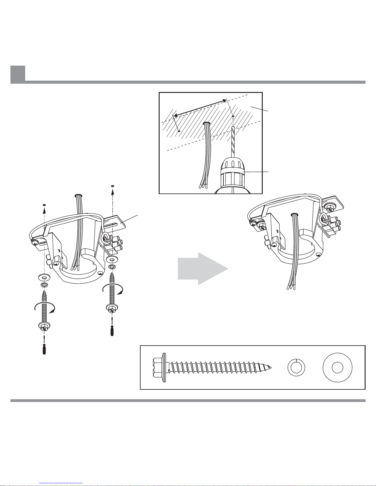
Hanger Bracket
Power Drill
90mm (3 ½ “)
Drill holes in Ceiling Joist at approximately
90mm (3 ½”) centres for Hanger Bracket
mounting.
Ceiling Joist behind
Secure Hanger Bracket to Ceiling Joist using screws
and washers provided. Ensure screws are securely
tightened.
IF THERE ARE ANY PROBLEMS DURING INSTALLATION OF THE FAN, THE INSTALLER MUST CONTACT THE
HUNTER PACIFICINTERNATIONAL WARRANTY LINE . TEL: 1300 360 280BEFORE LEAVING THE WORK SITE
Attaching Hanger Bracket directly to Ceiling
8
Page 11
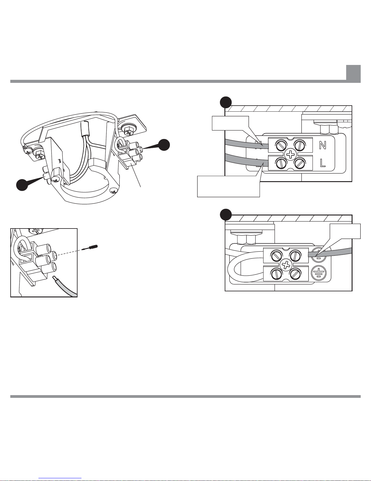
Make NEUTRAL and EARTH connections from incoming Mains
supply to NEUTRAL and EARTH terminals on Hanger Bracket as
appropriate. Make SWITCHED LIVE (Active) connection from Wall
Controller to LIVE terminal on Hanger Bracket.
UNSWITCHED LIVE (Active) wire from incoming Mains supply
should be looped to Wall Controller using an insulated joiner.
UNSWITCHED LIVE (Active) to be connected directly to
Hanger Bracket terminal.
must not
Terminal Block
EARTH
SWITCHED LIVE
from Wall Controller
NEUTRAL
B
Ensure that electrical connections
are good and that terminal block
screws are secure.
A
A
B
IF THERE ARE ANY PROBLEMS DURING INSTALLATION OF THE FAN, THE INSTALLER MUST CONTACT THE
HUNTER PACIFICINTERNATIONAL WARRANTY LINE . TEL: 1300 360 280BEFORE LEAVING THE WORK SITE
Connecting Live, Neutral and Earth Wires from Supply Wiring to Terminal Block on Hanger Bracket
9
Page 12
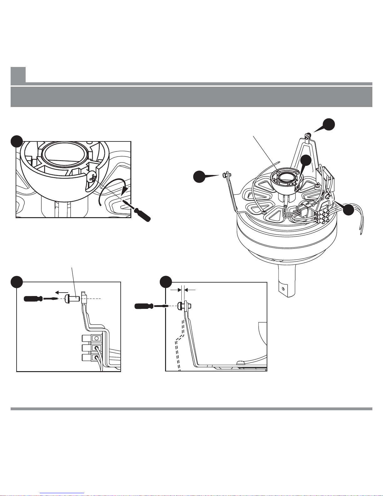
A
Remove one Fan Motor Housing fixing
screw, and put it aside for re-assembly
during Fan Motor Housing installation.
Check that the Suspension Ball fixing
screw is securely tightened.
Adjust remaining two Fan Motor Housing
fixing screws to provide clearance for
installing Fan Motor Housing.
6 - 8mm (1/4” - 5/8”)
C
Fan Motor Housing
Fixing Screw
B
C
Suspension Ball
C
B
A
IF THERE ARE ANY PROBLEMS DURING INSTALLATION OF THE FAN, THE INSTALLER MUST CONTACT THE
HUNTER PACIFICINTERNATIONAL WARRANTY LINE . TEL: 1300 360 280BEFORE LEAVING THE WORK SITE
Preparing Fan Motor Assembly
10
If installing a fan with a Suspension Rod, refer to Additional Instruction Manual for Suspended Installation for
remaining installation steps.
Page 13
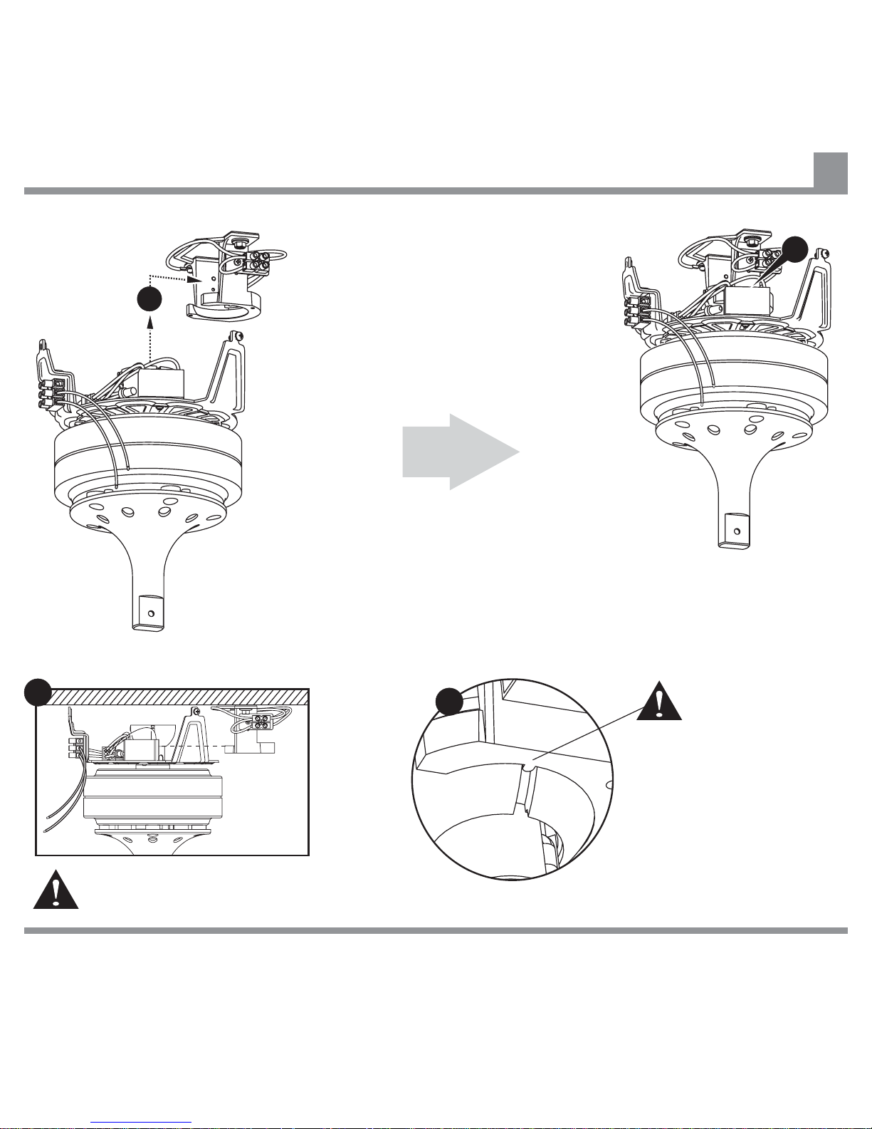
E
Ensure that lug on Hanger
Bracket is engaged in slot
in Suspension Ball.
Locate Suspension Ball in Hanger Bracket.
Position Fan Motor Assembly so that
Chassis arm with terminal block is facing
away from opening in Hanger Bracket.
Take care to keep Fan Motor Assembly level
during installation to avoid marking ceiling.
D
IF THERE ARE ANY PROBLEMS DURING INSTALLATION OF THE FAN, THE INSTALLER MUST CONTACT THE
HUNTER PACIFICINTERNATIONAL WARRANTY LINE . TEL: 1300 360 280BEFORE LEAVING THE WORK SITE
E
Installing Fan Motor Assembly into Hanger Bracket
11
D
Page 14
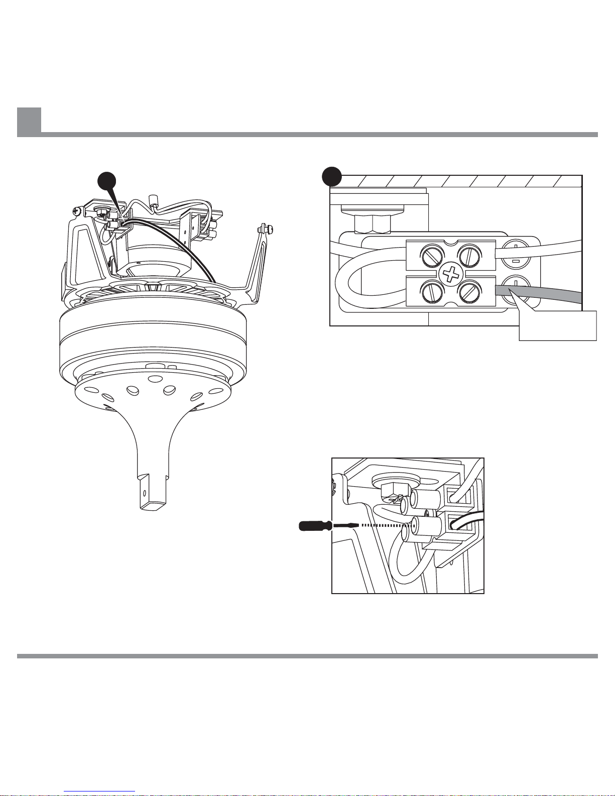
Ensure electrical connections are good, and
that terminal block screws are secure.
Make EARTH (Green/Yellow) connection from
Fan Motor Assembly to appropriate terminal
on Hanger Bracket.
IF THERE ARE ANY PROBLEMS DURING INSTALLATION OF THE FAN, THE INSTALLER MUST CONTACT THE
HUNTER PACIFICINTERNATIONAL WARRANTY LINE . TEL: 1300 360 280BEFORE LEAVING THE WORK SITE
A
Connecting Earth Wire from Fan Motor Assembly to Hanger Bracket
12
EARTH
(Green / Yellow)
A
Page 15
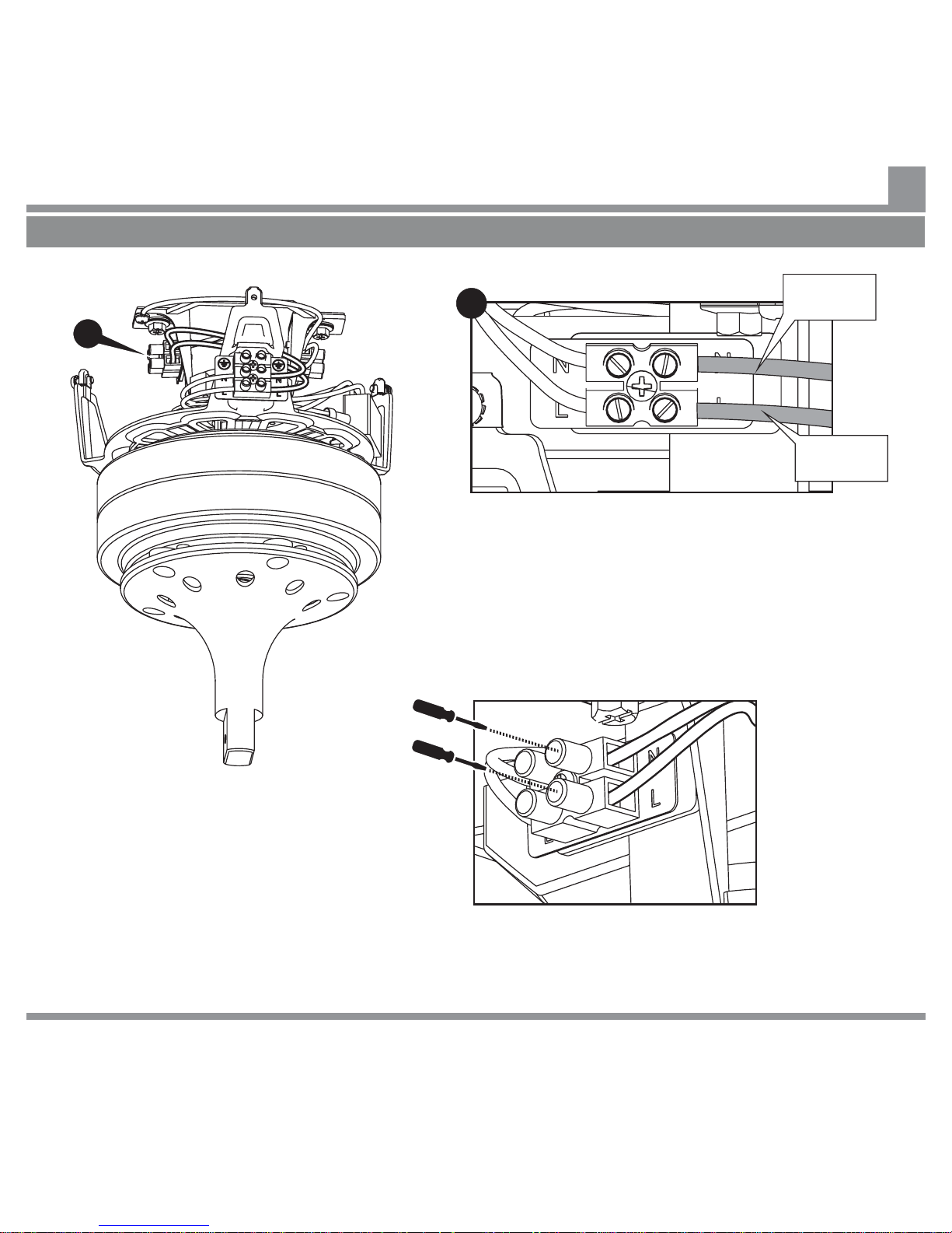
Make LIVE (Brown) and NEUTRAL (Blue)
connections from Fan Motor Assembly to
appropriate terminals on Hanger Bracket using preinstalled wires on right side of Chassis terminal
block, as shown.
IF THERE ARE ANY PROBLEMS DURING INSTALLATION OF THE FAN, THE INSTALLER MUST CONTACT THE
HUNTER PACIFICINTERNATIONAL WARRANTY LINE . TEL: 1300 360 280BEFORE LEAVING THE WORK SITE
If you are using a Remote Control, skip this step and go to page 18.
B
Connecting Live and Neutral Wires from Fan Motor Assembly to Hanger Bracket - Wall Controller
13
Ensure that electrical connections are good, and
terminal block screws are secure.
B
LIVE
(Brown)
NEUTRAL
(Blue)
Page 16
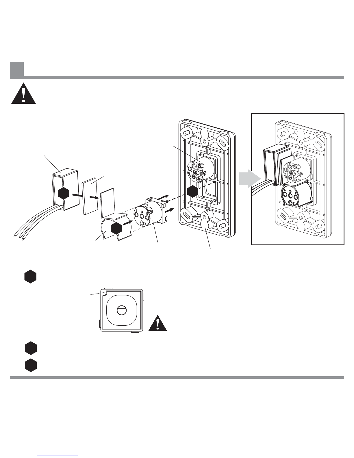
Attach Speed Controller to Back Plate.
Ensure that Orientation Mark is in top left corner, (viewed
from front), and numbers are oriented as shown.
Note: Back Plate, Face Plate
and ON/OFF Switch are not
supplied with fan.
Attach Capacitor to Clip using Double Sided Tape supplied.
Attach Clip to body of Speed Controller as shown.
Capacitor
0
1
2
3
Double Sided Tape
ON/OFF Switch
Clip
Orientation Mark
Back Plate
Speed
Controller
IF THERE ARE ANY PROBLEMS DURING INSTALLATION OF THE FAN, THE INSTALLER MUST CONTACT THE
HUNTER PACIFICINTERNATIONAL WARRANTY LINE . TEL: 1300 360 280BEFORE LEAVING THE WORK SITE
Warning: Do not attempt to control the operation of this fan from any wall controller that is not
approved by Hunter Pacific International Pty. Limited for use with this fan. Do not use a solid
state wall controller. The use of an unapproved wall controller voids the warranty.
Installing Wall Controller
14
1
1
2
2
3
3
Page 17
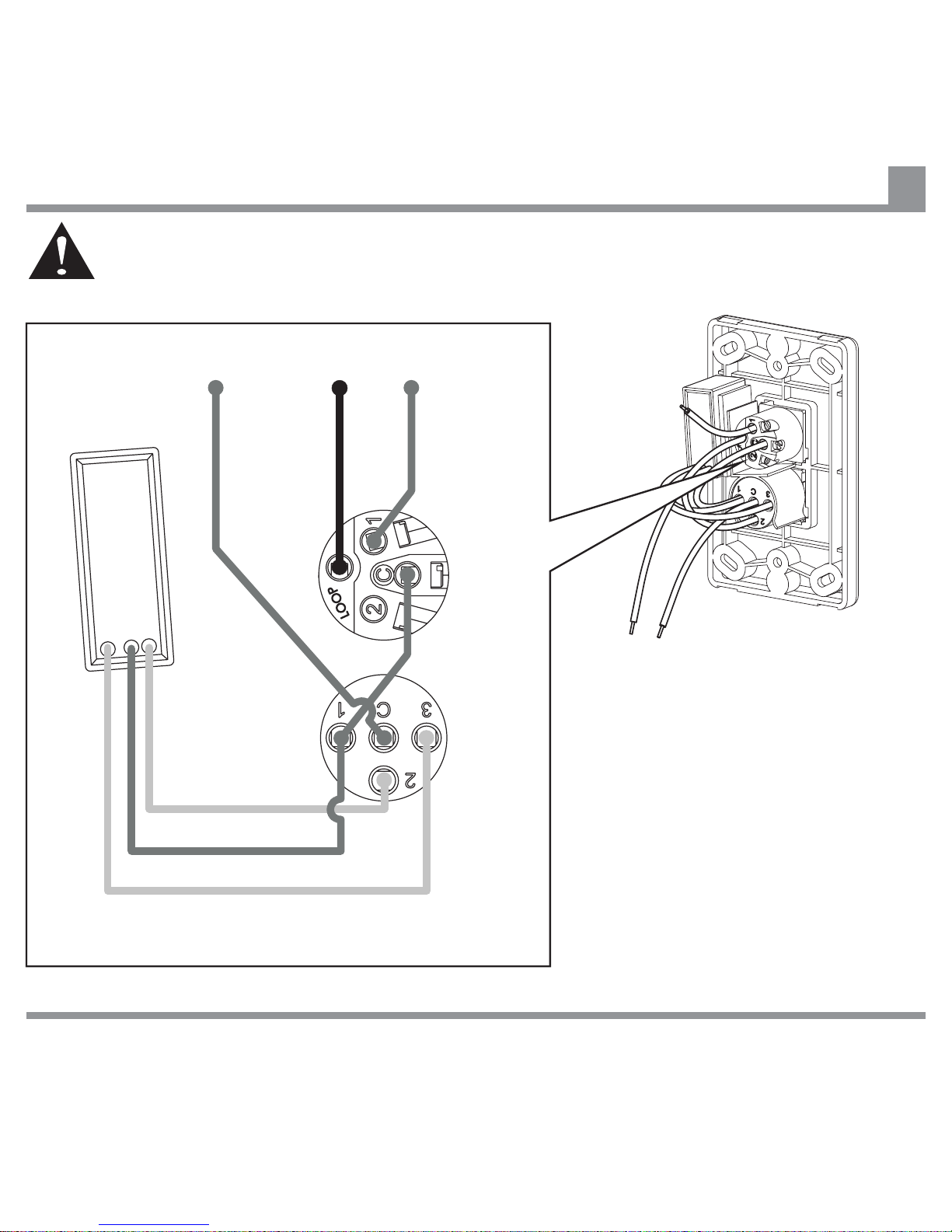
SWITCHED
LIVE
PURPLE
BROWN
RED
UNSWITCHED LIVE
NEUTRAL
To Fan Hanger Bracket
From Mains
Capacitor
ON/OFF
Switch
Speed
Controller
IF THERE ARE ANY PROBLEMS DURING INSTALLATION OF THE FAN, THE INSTALLER MUST CONTACT THE
HUNTER PACIFICINTERNATIONAL WARRANTY LINE . TEL: 1300 360 280BEFORE LEAVING THE WORK SITE
Note:
NEUTRAL wire may not be present in
some types of existing lighting circuit and
is not required. If present it may be
terminated as shown or otherwise
properly insulated.
Make electrical connections from Supply
Wiring to ON/OFF Switch, Speed
Controller, Capacitor and Fan Wiring as
shown. Ensure that electrical connections
are good, and terminal screws are secure.
Connecting Wires for Wall Controller
15
Warning: Do not attempt to control the operation of this fan from any wall controller that is not
approved by Hunter Pacific International Pty. Limited for use with this fan. Do not use a solid
state wall controller. The use of an unapproved wall controller voids the warranty.
Page 18
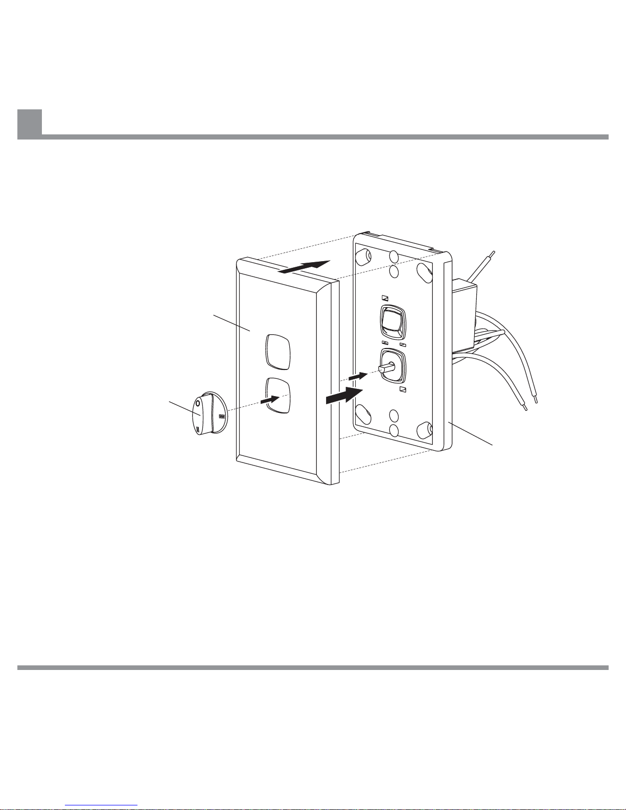
Rotary Speed Switch
Front Plate
Back Plate
IF THERE ARE ANY PROBLEMS DURING INSTALLATION OF THE FAN, THE INSTALLER MUST CONTACT THE
HUNTER PACIFICINTERNATIONAL WARRANTY LINE . TEL: 1300 360 280BEFORE LEAVING THE WORK SITE
Fix pre-wired Wall Controller Back Plate to wall, clip
on Front Plate, and press on Rotary Speed Switch.
Installing Front Plate and Rotary Speed Switch
16
Page 19
IF THERE ARE ANY PROBLEMS DURING INSTALLATION OF THE FAN, THE INSTALLER MUST CONTACT THE
HUNTER PACIFICINTERNATIONAL WARRANTY LINE . TEL: 1300 360 280BEFORE LEAVING THE WORK SITE
NEUTRAL from Main Supply
LIVE (Active) from Mains Supply
EARTH Conductor
E (Green/Yellow)
E (Green/Yellow)
E (Green/Yellow)
(Red)
(Blue)
(Orange)
C
3
1
2
C 2
1
Loop
L (Brown)
(Brown)
(Purple)
(Red)
N (Blue)
Capacitor
Capacitor
Hanger
Bracket
Earth
Chassis
Earth
Chassis
Terminal
Block
Fan
Motor
M
1~
Hanger Bracket
Terminal Blocks
NEUTRAL to Wall Switch not required
but may be present in some existing
installations.
ON / OFF
Switch
Rotary Speed
Switch
(Purple)
(Yellow)
(Red)
Wall Controller
Wall Plate
TO FAN N (Blue)
TO FAN L (Brown)
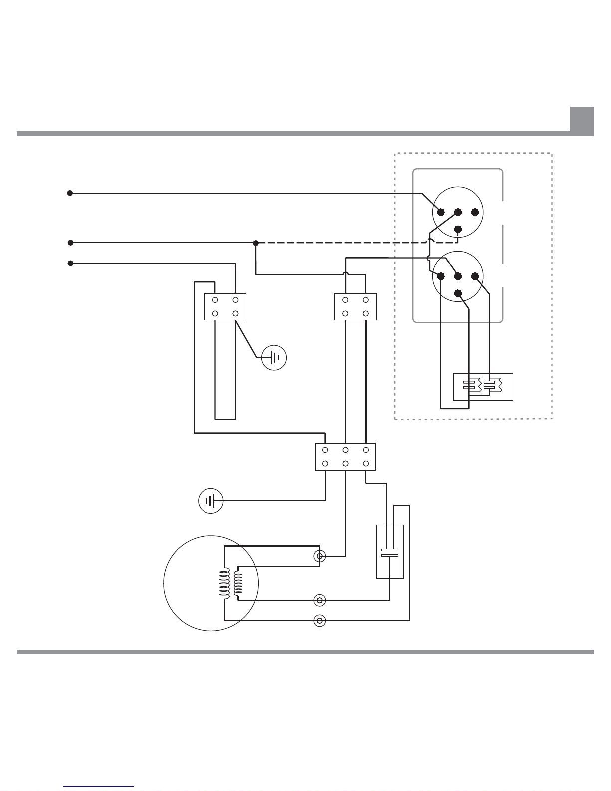
Wall Controller Installation Wiring Diagram
17
Page 20
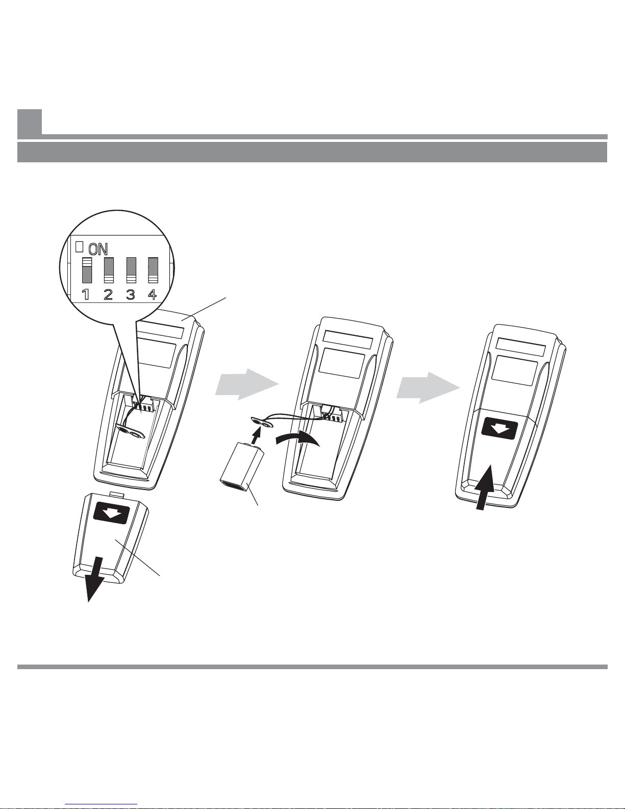
Battery
Compartment
Door
9v Battery
Remote Control
Handset
Check Remote Control Transmitter (Handset) CODE switch
settings are identical to Receiver CODE switch settings (use point
of ball point pen to adjust switches).
Note:
Remote Control Transmitter may vary from one shown.
Install Battery as shown.
If you are using a Wall Controller, skip these steps and go to Page 26.
IF THERE ARE ANY PROBLEMS DURING INSTALLATION OF THE FAN, THE INSTALLER MUST CONTACT THE
HUNTER PACIFICINTERNATIONAL WARRANTY LINE . TEL: 1300 360 280BEFORE LEAVING THE WORK SITE
Setting Code Switches for Remote Control Handset and Installing Battery
18
Page 21
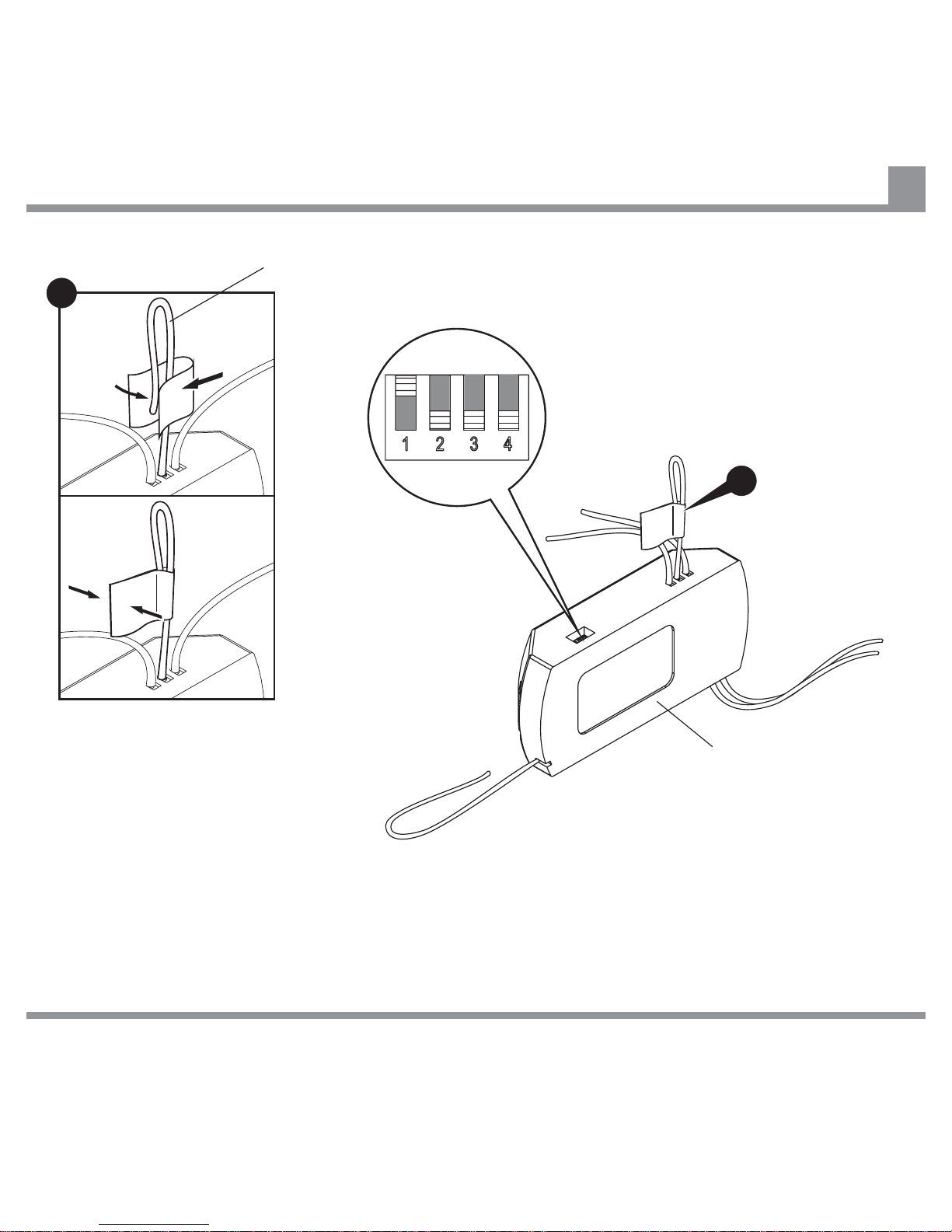
Check Remote Control Receiver CODE
switch settings and adjust if required (use
point of ball point pen to adjust switches).
Remote Control
Receiver
A
A
Light wire (White)
Terminate Remote Control
Receiver light wire (marked
LIGHT OUT) using good
quality electrical insulation
tape as shown.
IF THERE ARE ANY PROBLEMS DURING INSTALLATION OF THE FAN, THE INSTALLER MUST CONTACT THE
HUNTER PACIFICINTERNATIONAL WARRANTY LINE . TEL: 1300 360 280BEFORE LEAVING THE WORK SITE
Setting Code Switches for Remote Control Receiver
19
Page 22
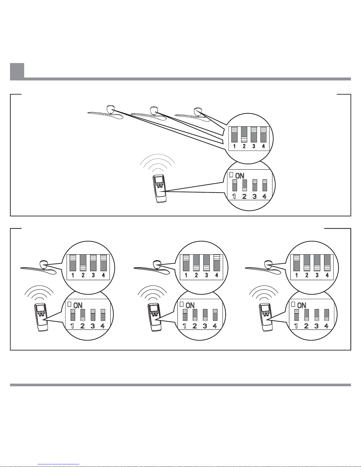
Setting Handset and Receiver Codes if using one Remote Control Handset to control multiple fans
Setting Handset and Receiver Codes if using individual Remote Control Handsets for each fan
Note: Ensure that the maximum distance from the Remote Control Handset to Receiver does not exceed
the range of the transmitter.
IF THERE ARE ANY PROBLEMS DURING INSTALLATION OF THE FAN, THE INSTALLER MUST CONTACT THE
HUNTER PACIFICINTERNATIONAL WARRANTY LINE . TEL: 1300 360 280BEFORE LEAVING THE WORK SITE
Code Settings for Remote Control Handset and Receiver
20
Page 23
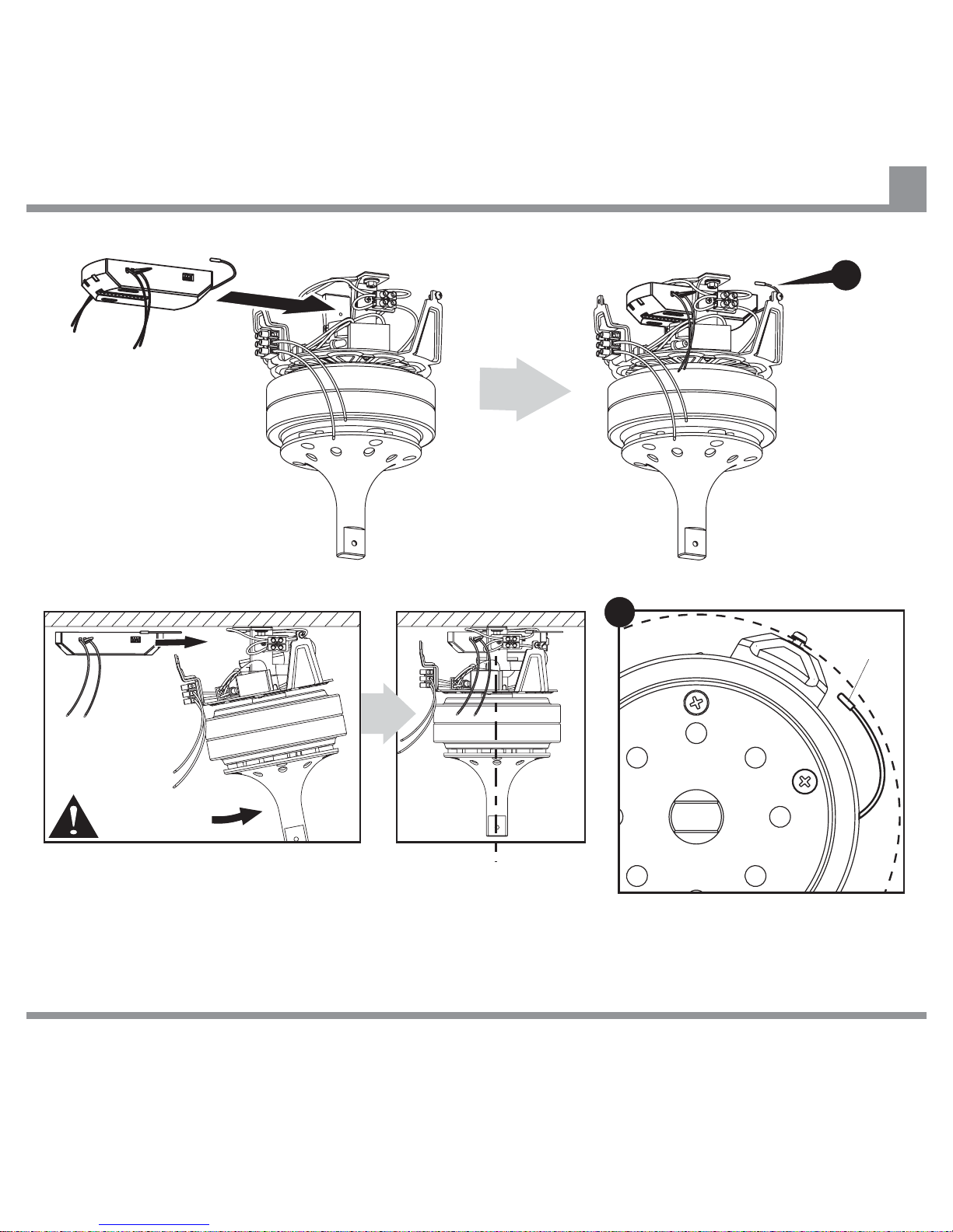
After installing Remote
Control Receiver readjust Fan Motor
Assembly to ensure
Drive Shaft is vertical.
Tilt Fan Motor Assembly as shown and
slide Remote Control Receiver into
Hanger Bracket in orientation shown
(Code switches to be passed through
Hanger Bracket).
Fix Remote Control Receiver Aerial
to ceiling within circle of Fan Motor
Housing.
A
A
IF THERE ARE ANY PROBLEMS DURING INSTALLATION OF THE FAN, THE INSTALLER MUST CONTACT THE
HUNTER PACIFICINTERNATIONAL WARRANTY LINE . TEL: 1300 360 280BEFORE LEAVING THE WORK SITE
Installing Remote Control Receiver in Hanger Bracket
21
Aerial
Page 24
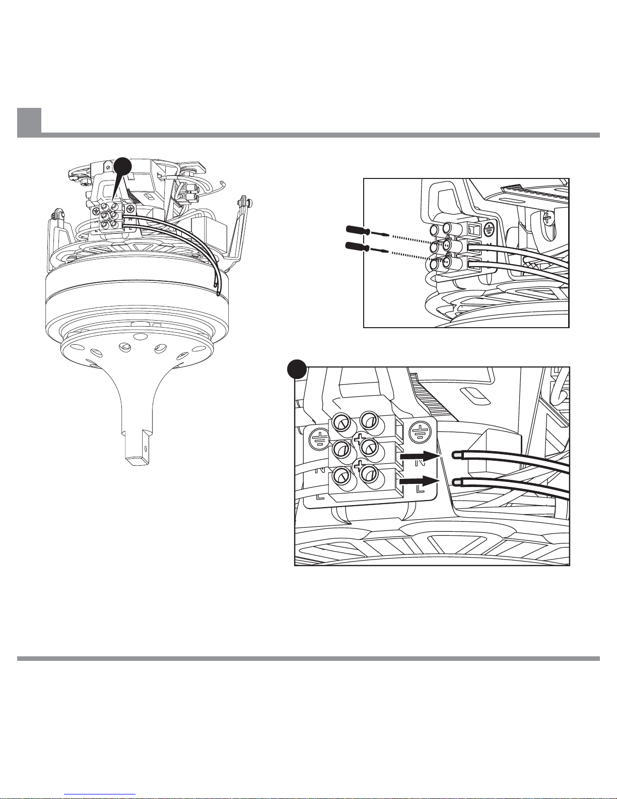
Remove pre-installed LIVE (Brown) and
NEUTRAL (Blue) wires from right side of terminal
block on Fan Motor Assembly.
A
IF THERE ARE ANY PROBLEMS DURING INSTALLATION OF THE FAN, THE INSTALLER MUST CONTACT THE
HUNTER PACIFICINTERNATIONAL WARRANTY LINE . TEL: 1300 360 280BEFORE LEAVING THE WORK SITE
A
Removing pre-installed Live and Neutral Wires from Fan Motor Assembly
22
Page 25
B
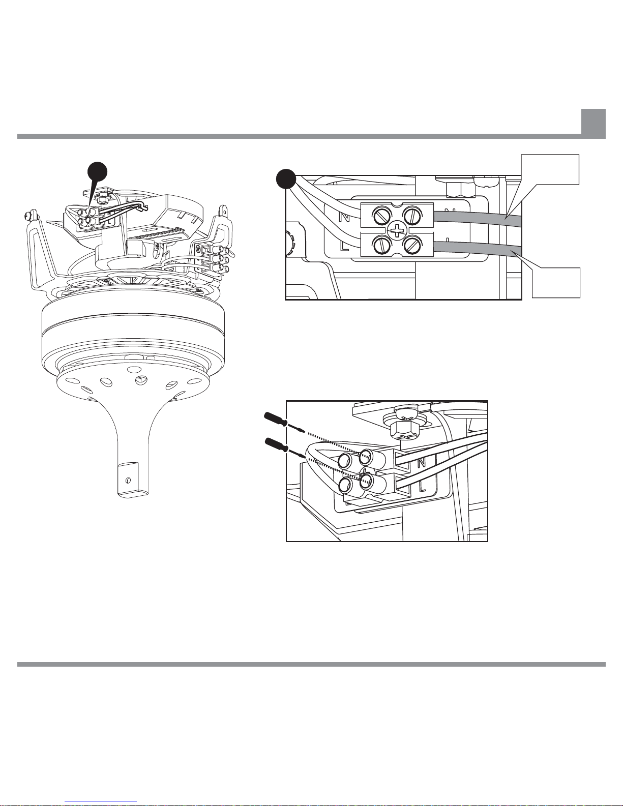
Make LIVE and NEUTRAL connections from Remote
Control Receiver to appropriate terminals on Hanger
Bracket using wires marked LIVE IN (Brown) and
NEUTRAL IN (Blue).
Ensure that electrical connections are
good, and terminal block screws are
secure.
LIVE
(Brown)
NEUTRAL
(Blue)
IF THERE ARE ANY PROBLEMS DURING INSTALLATION OF THE FAN, THE INSTALLER MUST CONTACT THE
HUNTER PACIFICINTERNATIONAL WARRANTY LINE . TEL: 1300 360 280BEFORE LEAVING THE WORK SITE
B
Connecting Live and Neutral Wires from Remote Control Receiver to Hanger Bracket
23
Page 26
A
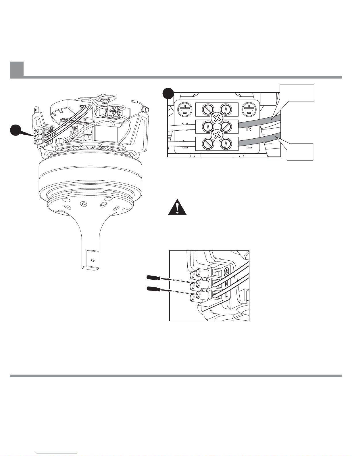
Make LIVE and NEUTRAL connections from Remote
Control Receiver to appropriate terminals on Fan Motor
Chassis using wires marked L (Brown) and N (Blue).
Ensure that electrical connections are good, and
terminal block screws are secure.
Ensure Remote Control Receiver LIGHT Wire is well
secured and cannot touch any moving parts.
LIVE
(Brown)
NEUTRAL
(Blue)
IF THERE ARE ANY PROBLEMS DURING INSTALLATION OF THE FAN, THE INSTALLER MUST CONTACT THE
HUNTER PACIFICINTERNATIONAL WARRANTY LINE . TEL: 1300 360 280BEFORE LEAVING THE WORK SITE
A
Connecting Live and Neutral Wires from Remote Control Receiver to Fan Motor Assembly
24
Page 27
IF THERE ARE ANY PROBLEMS DURING INSTALLATION OF THE FAN, THE INSTALLER MUST CONTACT THE
HUNTER PACIFICINTERNATIONAL WARRANTY LINE . TEL: 1300 360 280BEFORE LEAVING THE WORK SITE
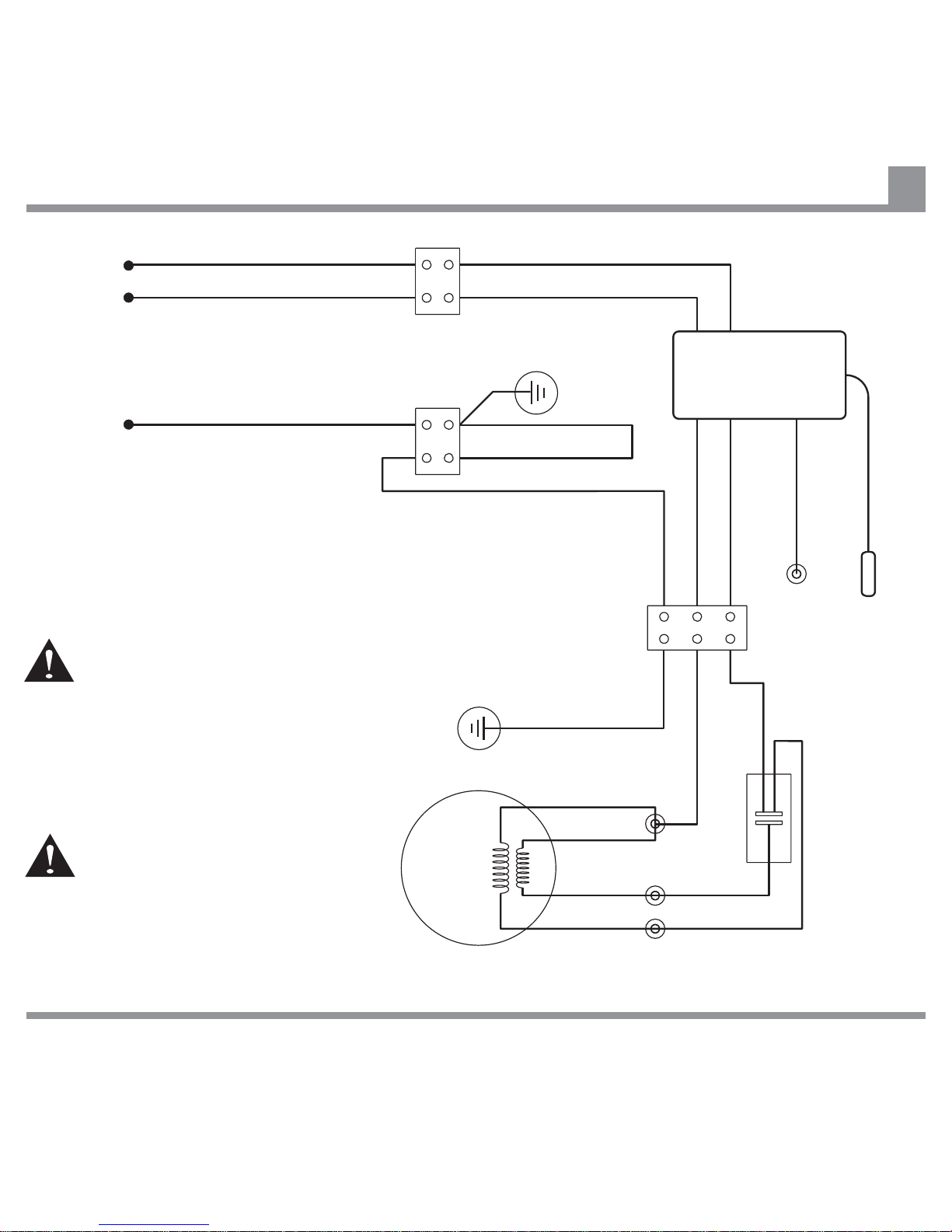
Note:
As shown, the Remote Control
Receiver is wired in series between
the Hanger Bracket terminal and the
Chassis terminal.
The SWITCHED LIVE (Active) wire
come via a Wall Switch. This
allows the fan to be manually
switched off, should a fault ever
develop.
MUST
Do not cut or shorten the Aerial wire
without folding the cut end over and
insulating with three layers of good
quality electrical insulation tape.
Remote Control (Accessory) Installation Wiring Diagram
25
SWITCHED LIVE (Active) from Wall Switch
NEUTRAL from Mains Supply
EARTH Conductor
E (Green/Yellow)
E (Green/Yellow)
(Purple)
(Yellow)
(Red)
(Orange)
(Red)
(Blue)
TO FAN (Blue)N
TO FAN (Brown)L
E (Green/Yellow)
L (Brown)
Ariel (Black)
For Light (White)
N (Blue)
Capacitor
Chassis
Terminal
Block
Remote
Control
Receiver
Hanger
Bracket
Earth
Chassis
Earth
Fan
Motor
Hanger
Bracket
Terminal
Blocks
AC IN (Brown)L
AC IN (Blue)N
M
1~
WARNING
Page 28
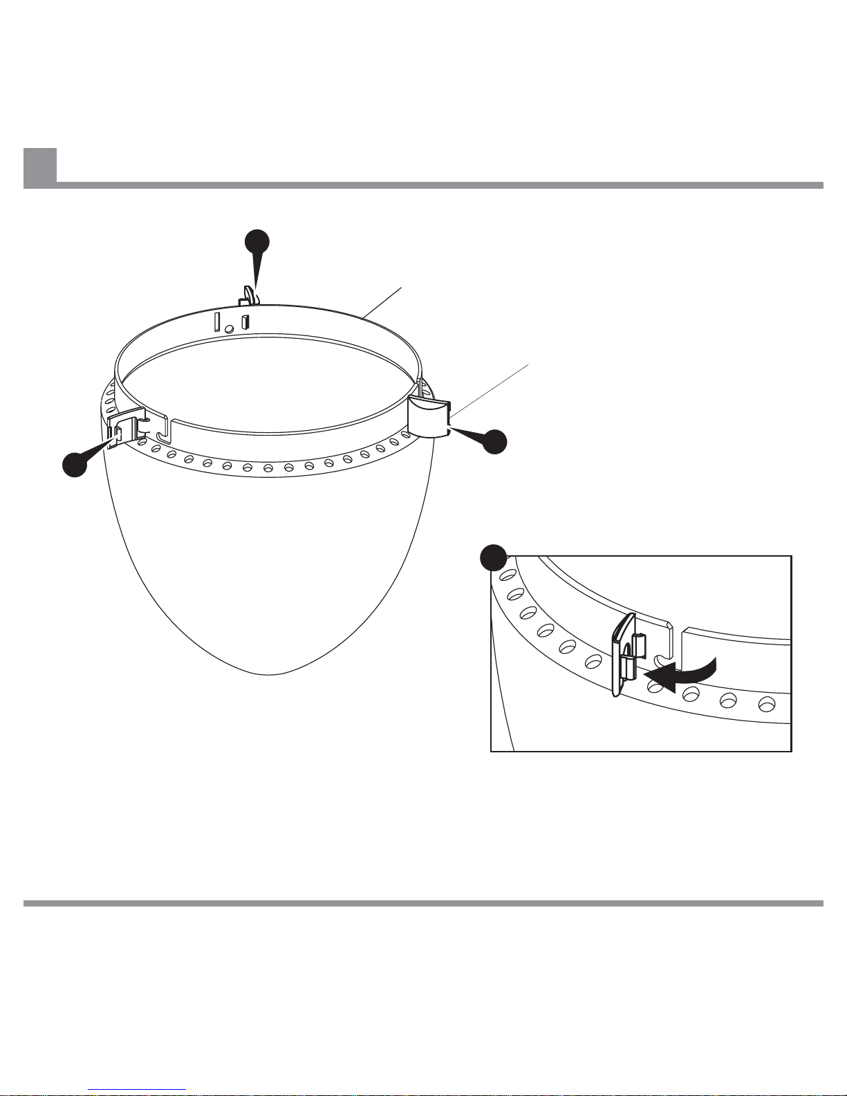
Preparing Fan Motor Housing
26
Fan Motor Housing
Fan Motor Housing
Screw Cover
A
Ensure Fan Motor Housing Screw
Covers are in fully open position.
A
A
A
IF THERE ARE ANY PROBLEMS DURING INSTALLATION OF THE FAN, THE INSTALLER MUST CONTACT THE
HUNTER PACIFICINTERNATIONAL WARRANTY LINE . TEL: 1300 360 280BEFORE LEAVING THE WORK SITE
Page 29
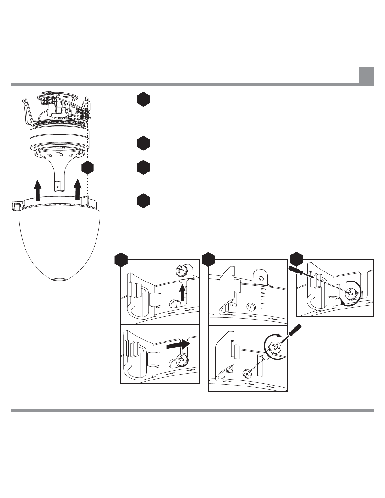
Attaching Fan Motor Housing to Fan Motor Assembly
27
Ensure that Fan Motor Housing fixing point with hole (not
bayonet slot) is aligned with Chassis arm from which fixing
screw was removed (see page 10).
Install Fan Motor Housing using a clockwise bayonet action.
Line up fixing hole in Fan Motor Housing with screw hole in
Chassis arm and install fixing screw removed on page 10.
Secure Fan Motor Housing, ensuring all three screws are tight
but not over tight.
IF THERE ARE ANY PROBLEMS DURING INSTALLATION OF THE FAN, THE INSTALLER MUST CONTACT THE
HUNTER PACIFICINTERNATIONAL WARRANTY LINE . TEL: 1300 360 280BEFORE LEAVING THE WORK SITE
1
2
3
3
4
4
1
2
Page 30
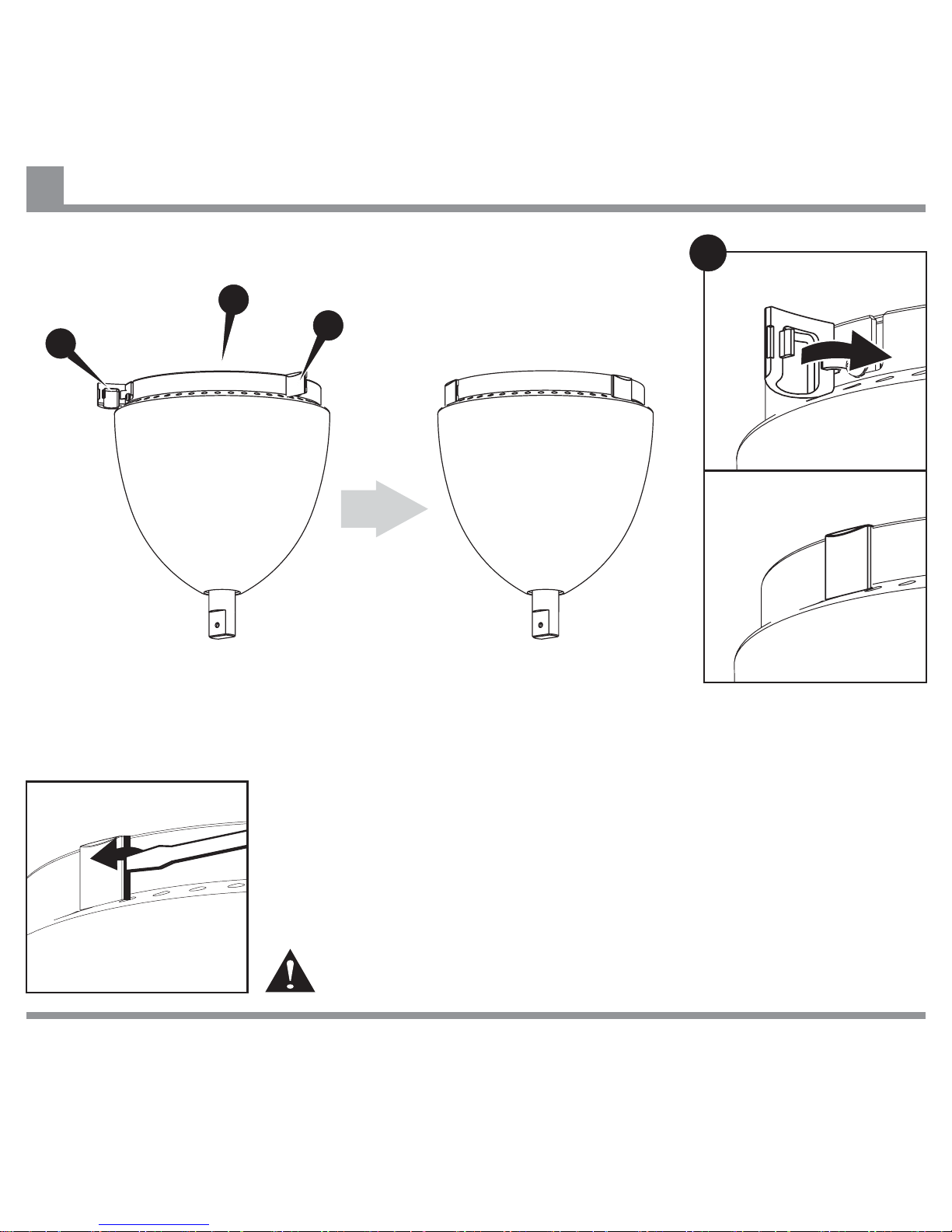
Closing Screw Covers
28
Close all three Screw
Covers.
Note: To remove Fan Motor Housing open Screw Covers using a flat bladed
screw driver as shown. Remove fixing screw from hole, loosen two bayonet
slot screws and remove Fan Motor Housing by rotating anticlockwise and
lowering.
A
IF THERE ARE ANY PROBLEMS DURING INSTALLATION OF THE FAN, THE INSTALLER MUST CONTACT THE
HUNTER PACIFICINTERNATIONAL WARRANTY LINE . TEL: 1300 360 280BEFORE LEAVING THE WORK SITE
A
A
A
Fan Blade must be removed before Fan Motor Housing is removed.
Page 31
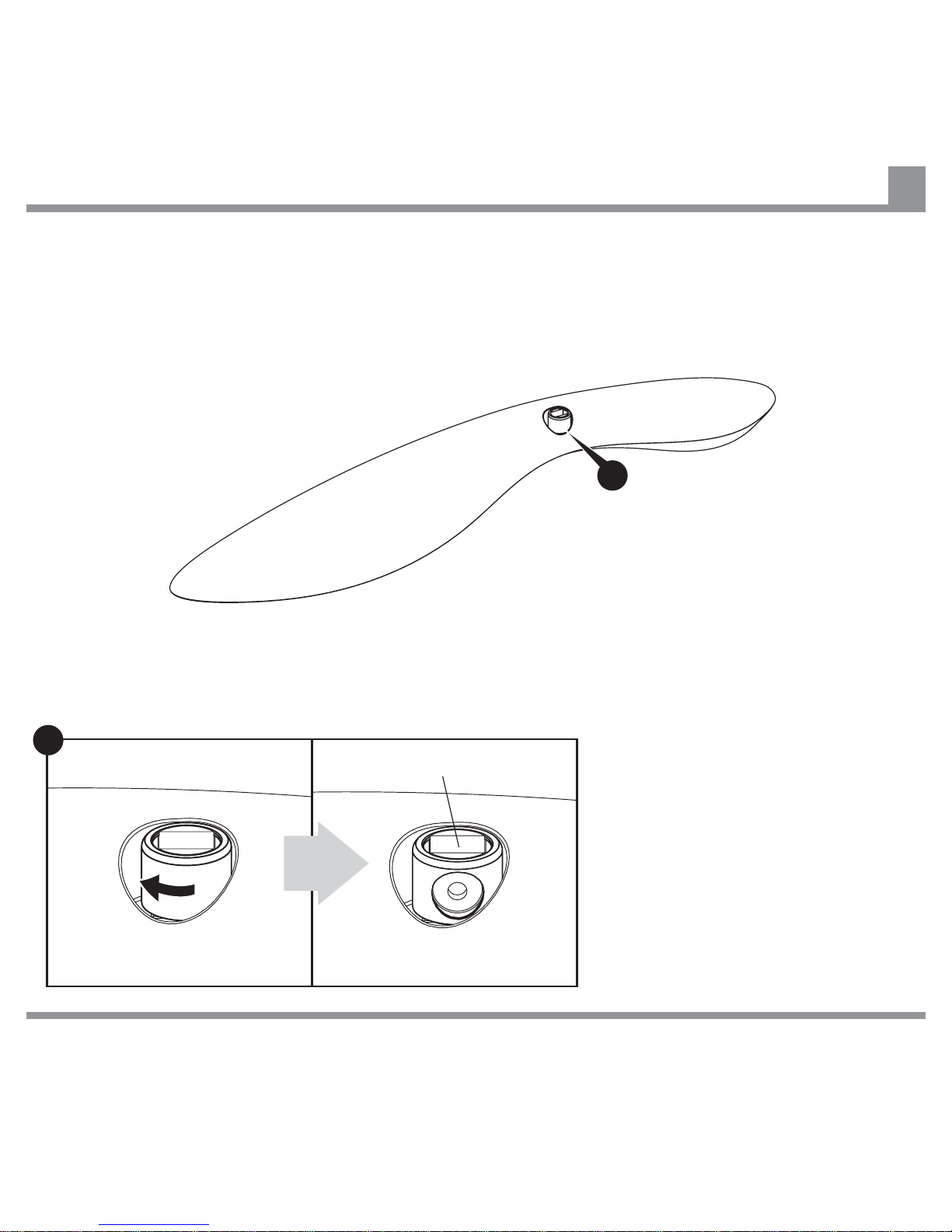
Preparing Fan Blade for Installation
29
B
Rotate Fan Blade Screw Cover to
expose fixing hole in Pivot Connector
as shown.
Pivot Connector
IF THERE ARE ANY PROBLEMS DURING INSTALLATION OF THE FAN, THE INSTALLER MUST CONTACT THE
HUNTER PACIFICINTERNATIONAL WARRANTY LINE . TEL: 1300 360 280BEFORE LEAVING THE WORK SITE
B
Page 32
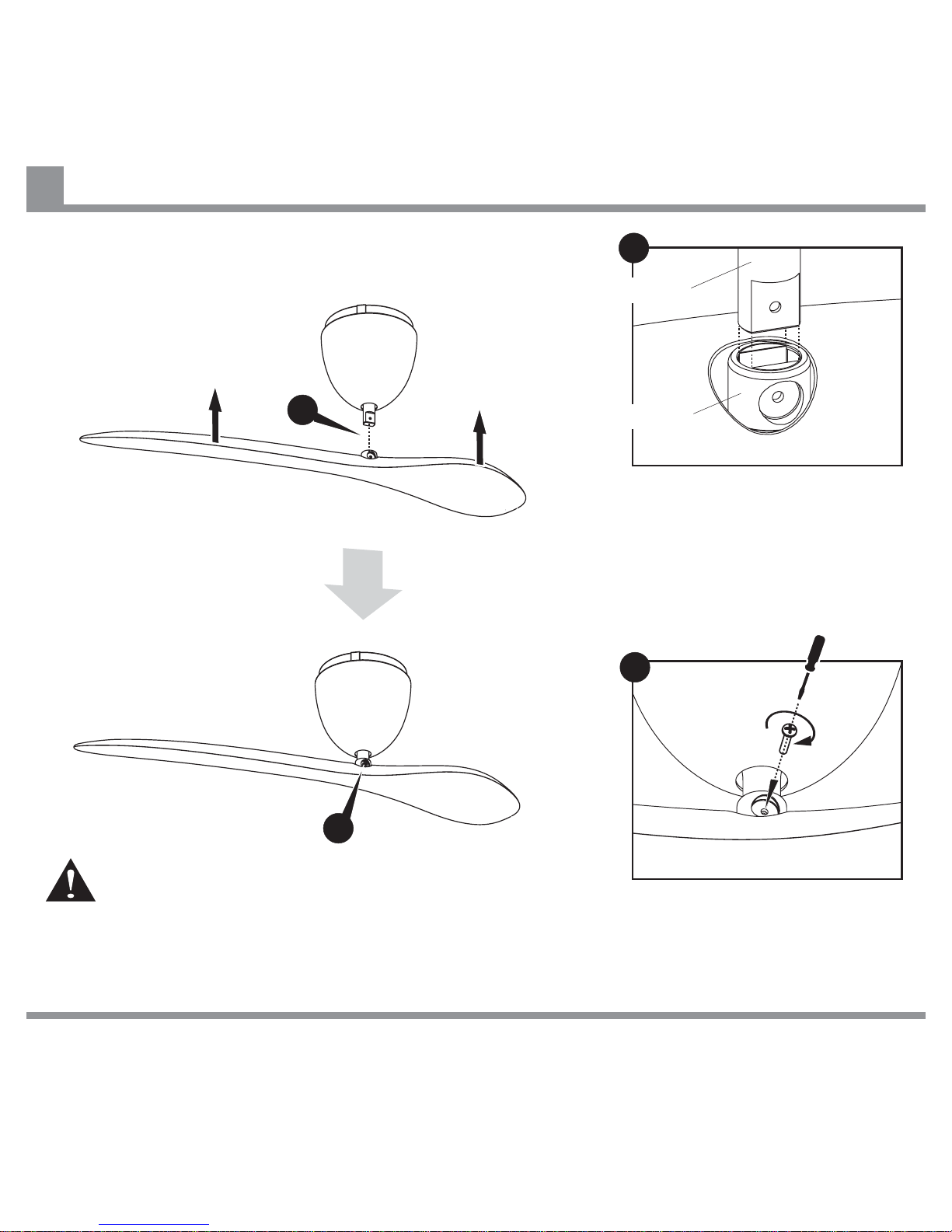
Attaching Fan Blade to Fan Motor Assembly
30
A
B
Align flats on Pivot Connector
with flats on Drive Shaft and
install Fan Blade by sliding
Pivot Connector onto Drive
Shaft.
Take care not to lift Drive Shaft when installing Fan Blade, as
this may disengage Suspension Ball from lug on Hanger
Bracket (see page11.)
Hold Fan Blade in position,
insert blade fixing screw and
tighten securely.
IF THERE ARE ANY PROBLEMS DURING INSTALLATION OF THE FAN, THE INSTALLER MUST CONTACT THE
HUNTER PACIFICINTERNATIONAL WARRANTY LINE . TEL: 1300 360 280BEFORE LEAVING THE WORK SITE
A
B
Drive Shaft
Pivot Connector
Page 33
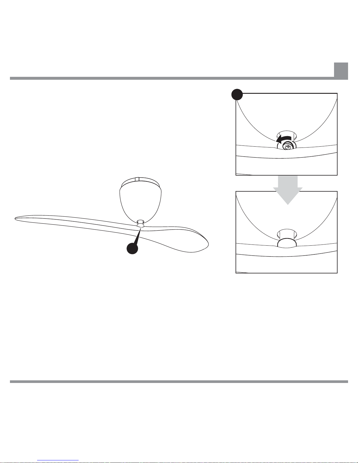
Closing Screw Cover on Pivot Connector
31
Rotate Screw Cover to hide
screw head. (Note: Rotating
the Screw Cover will prevent
blade fixing screw from falling
out should it become loose.)
IF THERE ARE ANY PROBLEMS DURING INSTALLATION OF THE FAN, THE INSTALLER MUST CONTACT THE
HUNTER PACIFICINTERNATIONAL WARRANTY LINE . TEL: 1300 360 280BEFORE LEAVING THE WORK SITE
C
C
Page 34
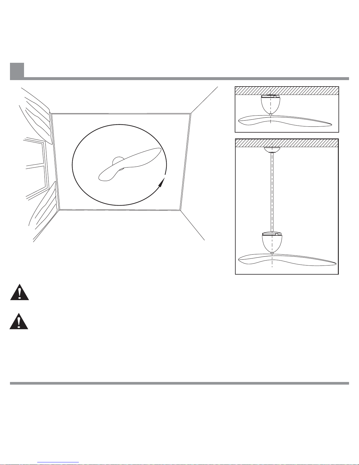
Installation Check
32
Rotate Fan Blade by hand to ensure it does not hit anything.
Make sure that the Drive Shaft is vertical, and that the gap between the Fan Motor Housing and
ceiling is even. If the Drive Shaft is not vertical, the fan may wobble.
Once the installation is completed and has been checked, the electricity supply can be turned
on at the main power box.
Ceiling
IF THERE ARE ANY PROBLEMS DURING INSTALLATION OF THE FAN, THE INSTALLER MUST CONTACT THE
HUNTER PACIFICINTERNATIONAL WARRANTY LINE . TEL: 1300 360 280BEFORE LEAVING THE WORK SITE
Page 35
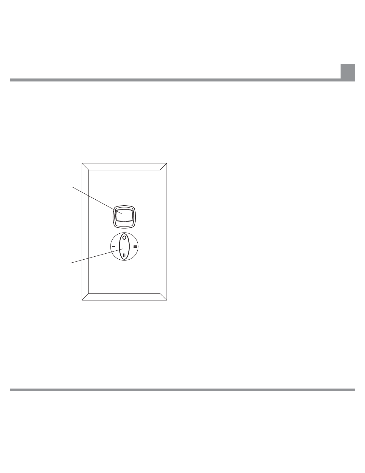
Operating your Sycamore Fan - Wall Controller
33
To operate your fan using a Wall Controller turn
the ON/OFF Switch to the ON position, then
turn the Rotary Speed Switch to the desired
speed setting:
0 - Off
I - High speed
II - Medium speed
III - Low speed.
ON/OFF Switch
Rotary Speed
Switch
IF THERE ARE ANY PROBLEMS DURING INSTALLATION OF THE FAN, THE INSTALLER MUST CONTACT THE
HUNTER PACIFICINTERNATIONAL WARRANTY LINE . TEL: 1300 360 280BEFORE LEAVING THE WORK SITE
Page 36
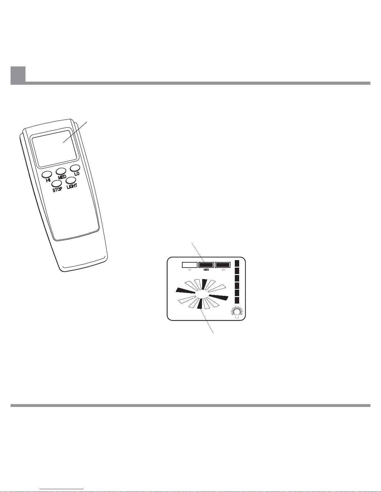
Operating your Sycamore Fan - Remote Control
34
To operate your fan using a Remote Control Handset, press the HI,
MED or LO button to select the desired speed.
To turn the fan off, press the STOP button.
To change between speeds, press the button for the new speed.
There is no need to stop the fan when changing speed.
The LIGHT button has no function on the Sycamore fan.
If the Remote Control Handset for your fan has an LCD display,
refer to the diagram below for an explanation of the symbols
displayed on the LCD screen.
LCD Screen
Speed Indicator
This symbol flashes when the fan is rotating.
IF THERE ARE ANY PROBLEMS DURING INSTALLATION OF THE FAN, THE INSTALLER MUST CONTACT THE
HUNTER PACIFICINTERNATIONAL WARRANTY LINE . TEL: 1300 360 280BEFORE LEAVING THE WORK SITE
Note:
Remote Control Transmitter may vary from one shown.
Page 37

Care and Cleaning
35
Regular cleaning of your Sycamore Ceiling Fan Blade and Fan Motor Housing is the only maintenance
that is needed. Due to the balanced single blade design, a large build up of dust on the blade may
eventually create an imbalance, causing the blade to wobble during use. This is likely to be more
apparent on fans with a suspended installation. Regular cleaning of the blade is recommended to
prevent dust from building up.
1. When cleaning your fan, only use a soft brush or lint free cloth to avoid scratching the finish. DO
NOT use water when cleaning your ceiling fan. It could damage the motor or the blade and/or
create the possibility of electric shock.
2. When dusting the Fan Blade, you must support the blade to prevent bending - no pressure should
be applied to the blade pivot. After cleaning the Fan Blade, check to ensure that the Drive Shaft is
vertical, otherwise the fan may wobble.
3. Occasionally, it may be necessary to re-tighten the Fan Blade and Fan Motor Housing fixing screws
to prevent any clicking or humming sounds during operation. This is especially true in climates with
broad temperature and humidity ranges, and for fans with high gloss painted blades or motor
housings.
4. If you experience any flaws in the operation of your fan, please check the points in the Trouble
Shooting section (see page 36).
IF THERE ARE ANY PROBLEMS DURING INSTALLATION OF THE FAN, THE INSTALLER MUST CONTACT THE
HUNTER PACIFICINTERNATIONAL WARRANTY LINE . TEL: 1300 360 280BEFORE LEAVING THE WORK SITE
Page 38

Trouble Shooting
36
WARNING: Except for items 1 and 2 below, the following require access to areas of the fan
which carry lethal voltage. There are no other checks which can be carried out by the user.
If the fan does not operate properly, or turns on or off at random.
If the fan is noisy.
If the fan rotates but does not create much airflow.
Apart from items 1 and 2, the following must be carried out by properly qualified personel.
1. If applicable, change the battery in the Remote Control Transmitter (Handset)
. Change the Wall Controller to the one originally supplied with the fan.
1. The room may contain items which obstruct the air flow.
2. The fan may be too small for the size of the room.
2. Check that the fan is switched on at the Wall Controller, and check the Rotary Speed Switch
position.
3. Check to ensure the Remote Control Code switches on the Remote Control Receiver and
Transmitter (Handset) are set to same positions. Sometimes the Handset Code switches may be
bumped when the battery is changed (see pages 18 to 20).
4. Check the main and branch circuit breakers and/or fuses.
5. Check the wire connections to the fan.
1. Check to make sure that the screws securing the Suspension Ball, Fan Motor Housing and Fan
Blade are tightened securely but are not over tight (see pages 10 ,27 and 30).
2. Check that all the screws in the Hanging Bracket are tight.
3
Note: In some areas, signals are sent through the power lines by the electricity supplier for the control of
off peak hot water, street lights and so on. These signals may cause an intermittent humming in the
ceiling fan. Filters are available in Australia at customer cost. It is not the fault of the ceiling fan.
IF THERE ARE ANY PROBLEMS DURING INSTALLATION OF THE FAN, THE INSTALLER MUST CONTACT THE
HUNTER PACIFICINTERNATIONAL WARRANTY LINE . TEL: 1300 360 280BEFORE LEAVING THE WORK SITE
Page 39

General information on Ceiling Fans
37
General Information.
Normal Wear and Tear.
1. All electrical motors, including fan motors make some noise, and may feel hot to the touch. This is
NOT a fault.
2. Ceiling fans tend to move during operation due to the fact that they are not rigidly mounted. (Rigid
mountings can generate excessive vibration and stress on the mountings). Movement of a couple
of centimetres is quite OK and does not suggest that the fan will fall down. The Sycamore fan is
mounted securely on a metal Hanger Bracket with rubber cushioning and a ball joint to allow free
movement. Please note that due to manufacturing variations not all Sycamore ceiling fans are
exactly the same - some may move more that others. Note: Excessive wobble can be caused by
the Drive Shaft not being positioned vertically. This can be easily rectified by adjusting the position
of the Fan Motor Assembly in the Hanger Bracket (see page 32).
3. Ceiling fans are an environmentally smart choice to help cool you in your home. They work by
creating air flow which causes a cooling sensation on the skin. The faster the speed of the air flow,
the greater the cooling sensation. Ceiling fans do not work by cooling the room, so they should be
switched off when there is no one in the room, to save energy. The effectiveness of ceiling fans is
also dependent on the humidity in the air - they are more effective in humid environments, and less
so in dry ones.
4. During winter, a slowly turning fan may help to reduce heating costs. Warm air rises to the ceiling,
where it cannot be felt by the occupants of a room, especially in areas with high ceilings. The fan
helps to keep warm air away from the ceiling, and mixes it with the air below. Keep the fan speed
low, so that the effects of evaporative cooling are minimised.
1. Threaded components working slightly loose or parts even slightly damaged or bent during
vigorous cleaning or bumping can cause extra wobble and noise. This is not covered under
warranty, but care during maintenance and cleaning should prevent this from occurring.
IF THERE ARE ANY PROBLEMS DURING INSTALLATION OF THE FAN, THE INSTALLER MUST CONTACT THE
HUNTER PACIFICINTERNATIONAL WARRANTY LINE . TEL: 1300 360 280BEFORE LEAVING THE WORK SITE
Page 40
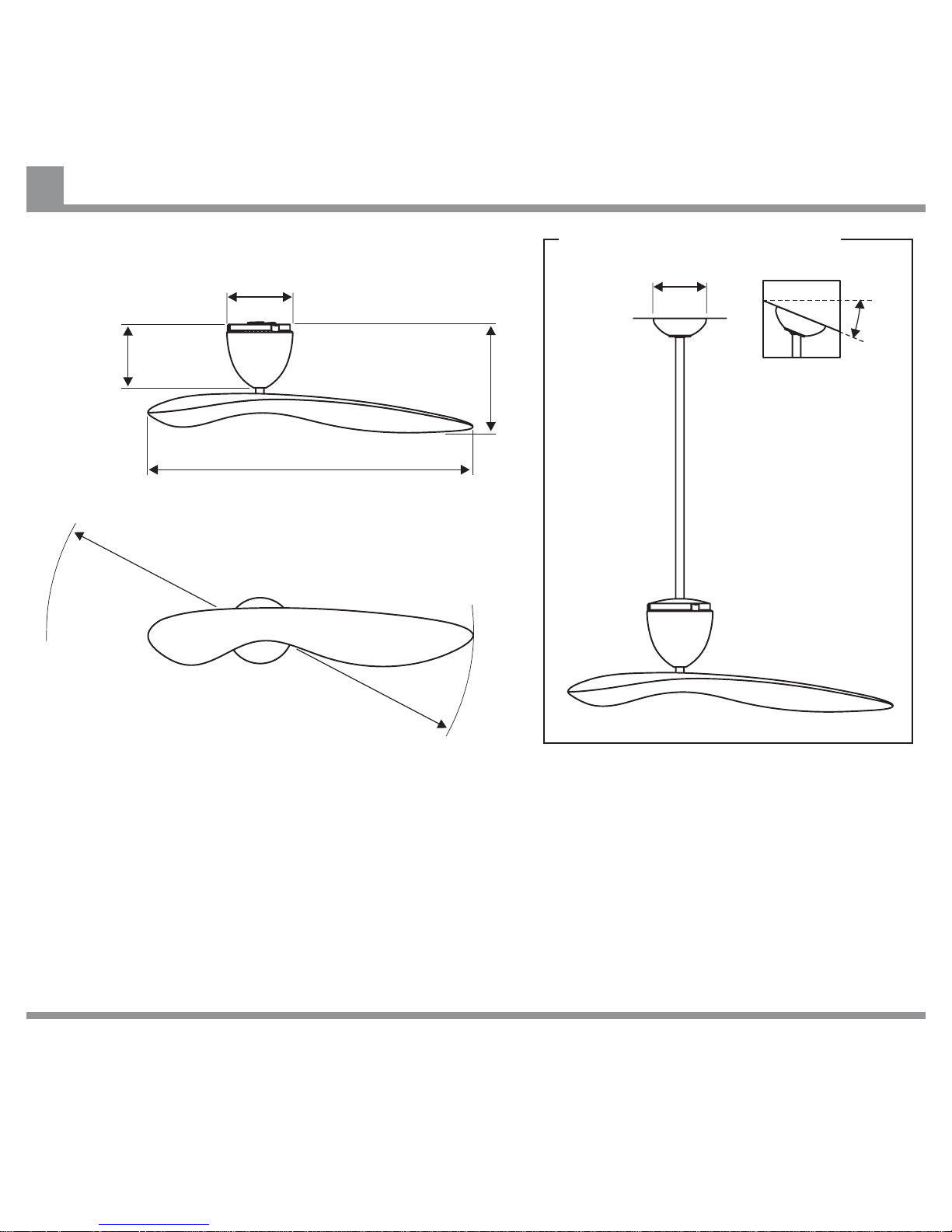
Technical Specifications
38
210 mm
170 mm
1000 mm
365 mm
1372 mm
205 mm
Colour
Motor Housing: Black / White / Brushed Aluminium
Hand Held, RF
Blade: Black / White / Brushed Silver
Remote Control
(Accessory)
IF THERE ARE ANY PROBLEMS DURING INSTALLATION OF THE FAN, THE INSTALLER MUST CONTACT THE
HUNTER PACIFICINTERNATIONAL WARRANTY LINE . TEL: 1300 360 280BEFORE LEAVING THE WORK SITE
Operating Speeds
Rated Power Consumption
Low: 80 rpm
Medium: 120 rpm
High: 160 rpm
35W
(Approximate figures at 230 - 240v AC)
Suspended Version (Accessory)
910mm and 1800mm Suspension Rods available
Standard Suspension
Kit suitable for raked
ceilings up to 22 . 45
Kit also available.
oo
22
o
Page 41

Warranty
39
IF THERE ARE ANY PROBLEMS DURING INSTALLATION OF THE FAN, THE INSTALLER MUST CONTACT THE
HUNTER PACIFICINTERNATIONAL WARRANTY LINE . TEL: 1300 360 280BEFORE LEAVING THE WORK SITE
Ceiling Fan Warranty.
Ceiling Fan Warranty Period.
Remote Control Warranty Period.
Balance of Warranty on Repaired or Replaced Products.
Transfer of Warranty.
You must have the original purchase receipt or bill of sale to make a warranty claim. No claim will be
accepted unless proof of date of purchase is available at the time of making the warranty claim.
The ceiling fan itself, excluding accessories such as the Remote Control Transmitter and Receiver, is
covered by a 2 year in-home warranty. During this period, Hunter Pacific International Pty. Limited will, at
its discretion, repair or replace defective product. Labour and product delivery costs are bourn by Hunter
Pacific International Pty. Limited during this 2 year period. The cost of obtaining or using special access
equipment (scissor lifts, scaffolding etc.) is specifically excluded, and it is the responsibility of the owner
to provide such equipment and have it safely installed and operated.
Following the 2 year in-home warranty period, Hunter Pacific International Pty. Limited, offers a repair or
replacement warranty on the motor assembly only, for an additional 3 years. During this 3 years, the
owner is responsible for labour costs incurred in removing and re-installing the fan, and for transport
costs to Hunter Pacific International Pty. Limited’s repair centre. Return freight will be paid by Hunter
Pacific International Pty. Limited.
General Hunter Pacific International Pty. Limited Remote Control Receivers and Transmitters (Handsets)
are covered by a 1 year in-home warranty under the same conditions as described above for fans. The
additional 3 year repair or replacement warranty option is not offered for Remote Control Transmitters or
Receivers.
Any replaced or repaired product is covered only by the balance of the warranty remaining on the original
article.
If the dwelling where the fan or remote control is installed changes hands, the balance of the warranty
passes to the new owner, providing the original bill of sale for the product is retained by the new owner.
Warranty for the fan does not cover damage to the fan if it is moved from one dwelling to another during
the warranty period. The warranty is voided in total if the product is sold as second hand goods.
Page 42

Warranty
40
IF THERE ARE ANY PROBLEMS DURING INSTALLATION OF THE FAN, THE INSTALLER MUST CONTACT THE
HUNTER PACIFICINTERNATIONAL WARRANTY LINE . TEL: 1300 360 280BEFORE LEAVING THE WORK SITE
The following is NOT covered by warranty.
1. Any damage incurred after delivery to the owner that is not caused by a fault in the products
materials or workmanship; damage from lightning or power surges; incorrect installation; damage
due to incorrect installation; noise or other influence of ripple control or information access systems
operated over power delivery infrastructure; water damage of any kind; installation or use outdoors;
damage arising from connection to or use with alternative power systems (e.g. inverters, solar, etc.).
2. Ceiling fans not installed by a licensed electrician.
3. Repair of a ceiling fan used incorrectly, accidentally damaged, modified in any way or not serviced in
accordance with the maintenance instructions.
4. Travelling costs incurred by Hunter Pacific International Pty. Limited personnel or service agents
over 25km from a Hunter Pacific authorised service depot, and/or the cost of transporting and
insuring the ceiling fan between the nearest Hunter Pacific International Pty. Limited agents' service
depot and its normal location.
These costs must be met by the purchaser
5. Subject to any statutory provisions to the contrary, claims for damage to furniture, carpet, walls,
ceilings, foundations or any other consequential loss either directly or indirectly resulting from a
faulty ceiling fan.
6. Signals sent through the mains power supply by the electricity supplier for off peak hot water, and
other signals including those for street lights and such. These signals may cause an intermittent
humming in the ceiling fan. Filters are available from Hunter Pacific International Pty. Limited in
Australia at customer cost. It is not the fault of the ceiling fan.
7. Sycamore Ceiling Fans not purchased and installed in Australia.
8. A service call fee will be charged where; there is nothing wrong with the ceiling fan or; the defective
operation of the ceiling fan is due to failure of electricity or; the installation is not in accordance with
Hunter Pacific International Pty. Limited instructions and/or applicable local regulations or; the
defects have been caused by incorrect application or abuse of the ceiling fan or; the damage has
been caused by unauthorised persons attempting to repair the fan.
Page 43
Warranty
41
WARRANTY HOTLINE NUMBER 1300 360 280 (AUSTRALIA ONLY 9am TO 5pm EST)
Please Note: When phoning for warranty you will require the following information; date of purchase;
retailer from whom the fan was purchased; model and colour of the fan. The installing electricians details
may also be required.
SYCAMORE CEILING FAN WARRANTY DETAILS
Please File with your Purchase Receipt
Customer Details
Fan Details
Electricians Details
Name
Address
Post Code
Phone Number
Model
Blade Colour
Motor Housng Colour
Date of Purchase
Purchased From
Name of Electrician
Licence Number
IF THERE ARE ANY PROBLEMS DURING INSTALLATION OF THE FAN, THE INSTALLER MUST CONTACT THE
HUNTER PACIFICINTERNATIONAL WARRANTY LINE . TEL: 1300 360 280BEFORE LEAVING THE WORK SITE
Page 44

nature + technology
Sycamore Ceiling Fan
TM
All rights reserved. No part of this publication may be reproduced in any form or by any means without the prior written permission
of Sycamore Technology. Copyright © 2006 Sycamore Technology, Sydney, Australia
Sycamore is a registered trademark of Sycamore Technology.
S1 8/06
 Loading...