

Page 1

XML Model
User's Guide
Sybase
11.1
Windows
®
PowerDesigner
®
Page 2

DOCUMENT ID: DC20014-01-1110-01
LAST REVISED: June 2005
Copyright © 1991-2005 Sybase, Inc. All rights reserved.
Information in this manual may change without notice and does not represent a commitment on the part of Sybase, Inc. and its
subsidiaries.
Sybase, Inc. provides the software described in this manual under a Sybase License Agreement. The software may be used only in
accordance with the terms of the agreement.
No part of this publication may be reproduced, transmitted, or translated in any form or by any means, electronic, mechanical, manual,
optical, or otherwise, without the prior written permission of Sybase, Inc.
Use, duplication, or disclosure by the government is subject to the restrictions set forth in subparagraph (c)(1)(ii) of DFARS 52.2277013 for the DOD and as set forth in FAR 52.227-19(a)-(d) for civilian agencies.
Sybase, SYBASE (logo), ADA Workbench, Adaptable Windowing Environment, Adaptive Component Architecture, Adaptive Server,
Adaptive Server Anywhere, Adaptive Server Enterprise, Adaptive Server Enterprise Monitor, Adaptive Server Enterprise Replication,
Adaptive S erver Everyw here, Afaria, Answers Anywhere, AppModeler , APT Workb ench, APT-Build, APT-Edit, APT-Execute, APTTranslator, APTLibrary, ASEP, AvantGo,Backup Server, BayCam, Bit-Wise, BizTracker, Certified PowerBuilder Developer, Certified
SYBASE Professional, Certified SYBASE Professional Logo, ClearConnect, Client-Library, Client Services, CodeBank, Column
Design, ComponentPa ck, Conne ction Mana ger, Convoy/DM, Co pernicus, CSP, Dat a Pipeline, Data Wor kbench, D ataArchite ct,
Database Analyzer, DataExpress, DataServer, DataWindow, DB-Library, dbQueue, Developers Workbench, DirectConnect Anywhere,
DirectConnect, Distribution Director, Dynamic Mobility Model, e-ADK, E-Anywhere, e-Biz Integrator, E-Whatever, EC Gateway,
ECMAP, ECRTP, eFulfillment Accelerator, Electronic Case Management, Embedded SQL, EMS, Enterprise Application Studio,
Enterprise Client/Server, Enterprise Connect, Enterprise Data Studio, Enterprise Ma nager, Enterp rise Po rta l (logo), Enterprise SQL
Server Manager, Enterprise Work Architecture, Enterprise Work Designer, Enterprise Work Modeler, eProcurement Accelerator,
eremote, Everything Works Better When Eve rything Works T ogether, EWA, Financia l Fusion, Financial Fusion (and design), Fina ncial
Fusion Server, Formula One, Fusion Powered e-Finance, Fusion Powered Financial Destinations, Fusion Powered STP, Gateway
Manager, GeoPoint, GlobalFIX, iAnywhere, iAnywhere Solutions, ImpactNow, Industry Warehouse Studio, InfoMaker, Information
Anywhere, Information Everywhere, InformationConnect, I nstaHelp, Intelligent S elf-Care , InternetBuilder, iremote, iSc ript, Ja guar
CTS, jConnect for JDBC, KnowledgeBase, Logical Memory Manager, M2M Anywhere, Mach Desktop, Mail Anywhere S tudio,
MainframeC onnect, M aintenance E xpress, Manage Anywhere Studio, MAP, M-B usiness Anywhere, M-Business Channel, MBus iness
Network, MDI Access Server, MDI Database Gateway, media.splash, Message Anywhere Server, MetaWorks, MethodSet, mFolio,
Mirror Activator, ML Query, MobiCATS, MySupport, Net-Gateway, Net- Library, New Era of Networks, Next Generation Learning,
Next Generation Learning Studio, O DEVICE, OASiS, OASiS logo, ObjectConnect, ObjectCycle, OmniConnect, OmniSQL Access
Module, OmniSQL Toolkit, Open Biz, Open Business Interchange, Open Client, Open ClientConnect, Open Client/Server, Open
Client/Server Interfaces, Open Gateway, Open Server, Open ServerConnect, Open Solutions, Optima++, Partnerships that Work, PBGen, PC APT Execute, PC DB-Net, PC Net Library, PhysicalArchitect, Pocket PowerBuilder, PocketBuilder, Power++, Power
Through Knowle dge, pow er.sto p, Power A MC, Pow erBuilder, PowerBuilder Foundatio n Class Library, PowerDesigner,
PowerDimensions, PowerDynamo, Powering the New Economy, PowerScript, PowerSite, PowerSocket, Powersoft, PowerStage,
PowerStudio, PowerTips, Powersoft Portfolio, Powersoft Professional, PowerWare Desktop, PowerWare Enterprise, ProcessAnalyst,
Pylon, Pylon Anywhere, Pylon Application Server, Pylon Conduit, Pylon PIM Server, Pylon Pro, QAnywhere, Rapport, Relational
Beans, RemoteWare, RepConnector, Report Workbench, Report-Execute, Replication Agent, Replication Driver, Replication Server,
Replication Serve r Manager, Replica tion Toolkit, Resource Manager, RFID Anywhere, R W-DisplayLib , RW-Library, SAFE,
SAFE/PRO, SDF, Secure SQL Server, Secure SQL Toolset, Security Guardian, SKILS, smart.partners, smart.parts, smart.script, SQL
Advantage , SQL Anywhere, SQL Anywhere Studio, SQ L C ode Chec ker, SQL Debug, SQL Edit , SQL Edit/TPU, SQL Ever ywhere,
SQL Modeler, SQL Remote, SQL Server, SQL Server Manager, SQL SMART, SQL Toolset, SQL Server/CFT, SQL Server/DBM,
SQL Server SNMP SubAgent, SQL Station, SQLJ, Stage III Engineering, Startup.Com, STEP, SupportNow, S.W.I.F.T. Message
Format Libraries, Sybase Central, Sybase Client/Server Interfaces, Sybase Development Framework, Sybase Financial Server, Sybase
Gateways, Sybase IQ, Sybase Learning Connection, Sybase MPP, Sybase SQL Desktop, Sybase SQL Lifecycle, Sybase SQL
Workgroup, Sybase Synergy Program, Sybase Virtual Server Architecture, Sybase User Workbench, SybaseWare, Syber Financial,
SyberAssist, SybFlex, SybMD, SyBooks, System 10, System 11, System XI (logo), SystemTools, Tabular Data Stream, The Enterprise
Client/Server Company, The Extensible Software Platform, The Future Is Wide Open, The Learning Connection, The Model For
Client/Server Solutions, The Online Information Center, The Power of One, TotalFix, TradeForce, Transact-SQL, Translation Toolkit,
Turning Imaginatio n Into Reality, UltraLit e, Ultra Lit e.NET, UNIBOM, Unilib, Uninull, Unisep, Unistring, U RK Runtime Kit for
UniCode, Viewer, VisualWriter, VQL, WarehouseArchitect, Warehouse Control Center, Warehouse Studio, Warehouse WORKS,
Watcom, Watcom SQL, Watcom SQL Server, Web Deployment Kit, Web.PB, Web.SQL, WebSights, WebViewer, WorkGroup SQL
Server, XA-Library, XA-Server, XcelleNet, and XP Server are trademarks of Sybase, Inc. or its subsidiaries.
All other trademarks are property of their respective owners.
Page 3

Contents
About This Book ............................................................................................ix
1 XML Model Basics..............................................................1
Functional overview..................................................................2
What is an XML model? ...........................................................3
About XML.......................................................................... 4
Objects in an XML model...................................................5
How to link a child object to a parent object in an
XML model?.......................................................................8
Defining the XML model environment..................................... 10
Choosing the XML language of an XML model................ 10
Changing the XML language of an XML model................ 11
Selecting extended model definitions at model creation..13
Defining model options..................................................... 14
XML model extended dependencies................................15
Defining an XML model .......................................................... 17
Defining model properties ................................................17
Creating an XML model.................................................... 24
Opening an existing XML model ......................................28
Detaching an XML model from the workspace ................ 28
Saving and closing an XML model...................................29
2 Building an XML model....................................................31
XML diagram basics ............................................................... 32
Defining an XML diagram................................................. 32
Why build an XML diagram? ............................................ 33
Creating an XML diagram ................................................ 34
Defining elements...................................................................35
Defining element properties .............................................36
Creating an element.........................................................43
How to link a child object to an element?.........................45
Defining the attributes of an element................................ 46
Modifying element display preferences............................52
Linking child elements to a parent element...................... 52
Defining Any properties....................................................58
Modifying the Any display preference...............................61
XSM User's Guide iii
Page 4

Defining Any Attribute properties...................................... 61
Defining identity constraints.................................................... 64
Defining a unique constraint............................................. 64
Defining a key constraint.................................................. 66
Defining a keyRef constraint ............................................ 67
Creating an identity constraint.......................................... 69
Defining an identity constraint selector............................. 70
Defining an identity constraint field................................... 73
Defining groups....................................................................... 76
Defining a group of elements ........................................... 76
How to link a child object to a group of elements?........... 81
Modifying the group display preference ........................... 82
Defining a group of attributes........................................... 82
Managing external shortcuts through references and data
types ....................................................................................... 87
Defining simple types.............................................................. 89
What is a simple type?..................................................... 89
Defining simple type properties........................................ 90
Modifying the simple type display preference................... 90
Creating a simple type...................................................... 90
Defining complex types........................................................... 92
What is a complex type?.................................................. 92
Defining complex type properties..................................... 93
Modifying complex type display preferences.................... 96
Creating a complex type................................................... 96
How to link a child object to a complex type?...................98
Defining simple content properties................................. 100
Defining complex content properties.............................. 101
Defining derivations .............................................................. 102
Deriving by extension..................................................... 102
Deriving by restriction..................................................... 104
Deriving by list................................................................ 112
Deriving by union............................................................ 113
Defining annotations.............................................................115
Defining annotation properties ....................................... 116
Defining documentation properties ................................ 116
Defining application information properties.................... 117
Creating an annotation................................................... 118
Defining notations.................................................................120
Defining notation properties ........................................... 120
Creating a notation......................................................... 121
Defining entities .................................................................... 122
Defining entity properties................................................ 122
Creating an entity........................................................... 123
Defining import, include and redefine ................................... 125
Defining an import.......................................................... 125
iv PowerDesigner
Page 5

Defining an include......................................................... 127
Defining a redefine ......................................................... 128
Defining business rules......................................................... 132
What is a business rule?................................................ 132
Defining business rule properties...................................132
Creating a business rule................................................. 133
Applying a business rule to an XML object .................... 135
3 Working with an XML model .........................................139
Checking an XML model.......................................................140
XML model check options .............................................. 140
XML model object selection in the Check Model ........... 141
Checking an XML model................................................142
Displaying previously applied check options in an
XML model.....................................................................144
Making corrections based on XML model check
results............................................................................. 145
XML Model objects verified by Check Model........................ 147
Group particle check ...................................................... 147
Model check ...................................................................148
Business rule check in an XSM...................................... 149
Data source check ......................................................... 149
File check .......................................................................150
Entity check....................................................................151
Include check ................................................................. 152
Simple type check .......................................................... 152
Complex type check.......................................................152
Element check................................................................ 153
Group check...................................................................155
Attribute check................................................................ 156
Notation check................................................................ 156
Attribute group check ..................................................... 157
Import check................................................................... 158
Redefine check............................................................... 158
Key check....................................................................... 159
KeyRef check.................................................................160
Unique check.................................................................. 161
Extended object check ...................................................162
Extended link check .......................................................162
Replication check ........................................................... 163
Extension check ............................................................. 163
Restriction check............................................................163
Simple type list check..................................................... 164
Simple type union check ................................................165
Annotation check............................................................ 165
Mapping objects in an XML model........................................166
XSM User's Guide v
Page 6

Understanding object mapping ...................................... 166
Defining data sources in an XML model ........................ 166
Mapping XML Model objects to PDM objects ................ 169
Mapping XML Model objects to OOM objects................ 171
Creating a mapping for an XML object........................... 172
Modifying the mapping of an attribute............................ 175
Manipulating XML objects graphically................................... 176
Local objects .................................................................. 176
Global objects................................................................. 177
Example: converting a local object into a global object.. 177
Comparing and merging XML models.................................. 179
Generating an XML model from a Physical Data Model....... 180
Generating XML Model objects...................................... 180
Generating and updating an XML model ....................... 181
Defining XML model generation options ........................ 182
Generating a new XML model from a PDM ................... 184
Updating an existing XML model ................................... 185
Generating an XML model from an Object-Oriented Model . 188
Generating XML Model objects...................................... 188
Generating and updating an XML model ....................... 189
Defining XML model generation options ........................ 190
Generating a new XML model from an OOM................. 192
Updating an existing XML model ................................... 193
Editing an XML model report ................................................ 196
What is a report?............................................................ 196
Creating an XML model report....................................... 196
How can a report underline the hierarchical structure
of an XML model?..........................................................198
4 Generating and reverse engineering an XSD,
a DTD or an XDR file......................................................201
Generating an XSD, a DTD or an XDR file........................... 202
Why generate an XSD file?............................................ 202
Why generate a DTD file?.............................................. 202
Why generate an XDR file?............................................ 202
Defining generation parameters..................................... 203
How to generate an XSD, a DTD or an XDR file?.......... 205
Reverse engineering an XSD, a DTD or an XDR file........... 208
What is reverse engineering? ........................................ 208
Why reverse engineer an XSD, a DTD or an XDR
file?................................................................................. 208
How to reverse engineer an XSD, a DTD or an XDR
file?................................................................................. 208
vi PowerDesigner
Page 7

5 Exchanging data with databases supporting XML......215
Why use XML in databases?................................................216
Generating an annotated schema for Microsoft SQL
Server 2000 .......................................................................... 217
Mapping XML objects to PDM objects ........................... 217
Reinforcing mapping with extended attributes ............... 225
Generating an annotated schema for Oracle 9i2..................230
Generating a DAD file for IBM DB2 ...................................... 237
Generating SQL/XML queries...............................................249
6 Generating from an XML model....................................255
Generation basics................................................................. 256
Target models parameters............................................. 256
Generating an XML model from an XML model ................... 259
Why generate an XML model from an XML model?......259
Generating and updating an XML model........................ 259
XML Model Glossary.........................................................................................267
Index .........................................................................................271
XSM User's Guide vii
Page 8

viii PowerDesigner
Page 9

About This Book
Subject
Audience
This book describes the PowerDesigner XML Model environment. It shows
you how to do the following:
♦ Build an XML model
♦ Work on an XML model
♦ Generate and reverse engineer a DTD file
♦ Generate and reverse engineer an XSD file
♦ Generate and reverse engineer an XDR file
♦ Generate an annotated schema
♦ Generate a DAD file
♦ Generate an SQL/XML query
♦ Generate an XML model from a PDM
♦ Generate an XML model from an OOM
♦ Generate an XML model from another XML model
This book is for anyone who will be designing or building an XML model
with PowerDesigner. It requires an understanding of XML. Some experience
with XML Schema might also be helpful but not required. For more
information, see the Bibliography section at the end of this chapter.
Documentation
primer
XSM User's Guide ix
The PowerDesigner modeling environment supports several types of models:
♦ Conceptual Data Model (CDM) to model the overall logical structure
of a data application, independent from any software or data storage
structure considerations
♦ Physical Data Model (PDM) to model the overall physical structure of
a database, taking into account DBMS software or data storage structure
considerations
Page 10

About This Book
♦ Object Oriented Model (OOM) to model a software system using an
object-oriented approach for Java or other object languages
♦ Business Process Model (BPM) to model the means by which one or
more processes are accomplished in operating business practices
♦ XML Model (XSM) to model the structure of an XML file using a DTD
or an XML schema
♦ Requirements Model (RQM) to list and document the customer needs
that must be satisfied during a development process
♦ Information Liquidity Model (ILM) to model the replication of
information from a source database to one or several remote databases
using replicati on engines
♦ Free Model (FEM) to create any kind of chart diagram, in a context-
free environment
This book only explains how to use the XML Model. For information on
other models or aspects of PowerDesigner, consult the following books:
General Features Guide To get familiar with the PowerDesigner
interface before learning how to use any of the models.
Conceptual Data Model Getting Started To learn the basics of the
CDM.
Conceptual Data Model User’s Guide To work with the CDM.
Physical Data Model Getting Started To learn the basics of the PDM.
Physical Data Model User’s Guide To work with the PDM.
Object Oriented Model Getting Started To learn the basics of the
OOM.
Object Oriented Model User's Guide To work with the OOM.
Business Process Model Getting Started To learn the basics of the
BPM.
Business Process Model User’s Guide To work with the BPM.
Requirements Model User’s Guide To work with the RQM.
Information Liquidity Model User’s Guide To work with the ILM.
Reports User’s Guide To create reports for any or all models.
x PowerDesigner
Page 11

About This Book
Repository Getting Started To learn the basics of the Repository.
Repository User’s Guide To work in a multi-user environment using a
central repository.
Typographic
conventions
Bibliography
PowerDesigner documentation uses specific typefaces to help you readily
identify specific items:
♦ monospace text (normal and bold)
Used for: Code samples, commands, compiled functions and files,
references to variables.
Example: declare user_defined…, the
BeforeInsertTrigger template.
♦ UPPER CASE
Object codes, reversed objects, file names + extension.
Example: The AUTHOR table appears in the Browser. Open the file
OOMAFTER.OOM.
♦ bold text
Any new term.
Example: A shortcut has a target object.
♦
SMALL CAPS
Any key name.
Example: Press the
ENTER key.
W3C XML R ecommendation – htt p://www.w3. org/TR/REC-xml
W3C DTD Recommend ation – http://www.w3.org/TR/REC-xml#dt-doct y pe
W3C XML Schema Recommendation –
http://www.w3.org/XML/Schema#dev
W3C XML-Data Note – http://www.w3.org/TR/1998/NOTE-XML-data0105/
XSM User's Guide xi
Page 12

About This Book
xii PowerDesigner
Page 13

CHAPTER 1
XML Model Basics
About this chapter
Contents
This chapter presents PowerDesigner XML Model. It provides you with an
introduction to the basic notions of XML modeling.
Topic Page
Functional overview 2
What is an XML model? 3
Defining the XML model environment 10
Defining an XML model 17
XSM User's Guide 1
Page 14
Functional overview
Functional overview
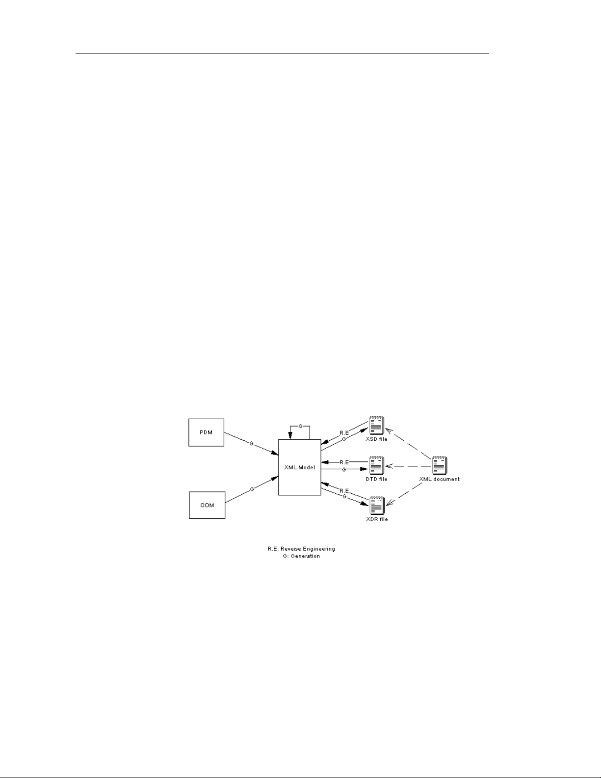
With the graphical interface and the Browser tree view of PowerDesigner
XML Model, you can design an XML diagram which represents the content
of an XML Schema Definition file (.XSD), a Document Type Definition file
(.DTD) or an XML-Data Reduced file (.XDR). Since XML structures can be
very complex, it is much ea s ier to visualize them through comprehensive and
explicit diagrams, than to read XML-coded pages.
Once you have created an XML diagram, you can generate an XSD, a DTD
or an XDR file to share the structure of an XML document via an ordinary
plain text file.
Conversely, you will be able to reverse engineer an XSD, a DTD or an XDR
file into an XML model, with its corresponding diagram.
The XML Model allows you to:
♦ Build an XML model
♦ Check an XML model
♦ Map objects in an XML model
♦ Edit a report of an XML model
♦ Generate and reverse engineer an XSD, a DTD or an XDR file
♦ Generate an XML model from a Physical Data Model (PDM)
♦ Generate an XML model from an Object Oriented Model (OOM)
♦ Generate an XML model from an XML model
2 PowerDesigner
Page 15

What is an XML model?
An XML model is a graphical representation of an XML Schema Definition
file (.XSD), a Document Type Definition file (.DTD) or an XML-Data
Reduced file (.XDR).
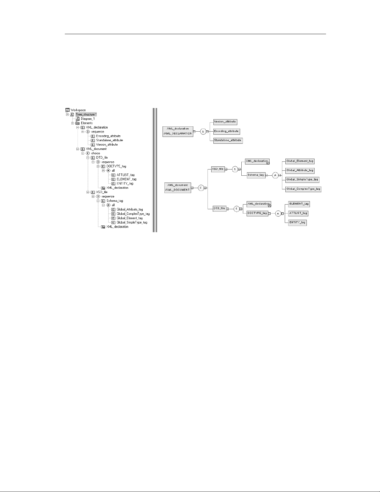
With its Browser tree view and diagram, an XML model gives you a global
and schematic view of all the elements composing an XSD, a DTD or an
XDR file. This is very helpful when you need to understand, check or modify
the complex structure of an XSD, a DTD or an XDR file.
Example of an XML model (Browser and diagram):
Chapter 1 XML Model Basics
Demo models
Demo XML models are available in the Examples directory.
XSM User's Guide 3
Page 16
What is an XML model?
About XML
Why use XML?
DTD, XSD or XDR
The eXtensible Markup Language is used for different reasons:
♦ It describes and structures data, whereas HTML only displays data
♦ It uses a self-describing and personalized syntax
♦ It can be exchanged between incompatible systems, since data is stored
in plain text format
The structure of an XML model is described by a DTD, an XSD or an XDR
file:
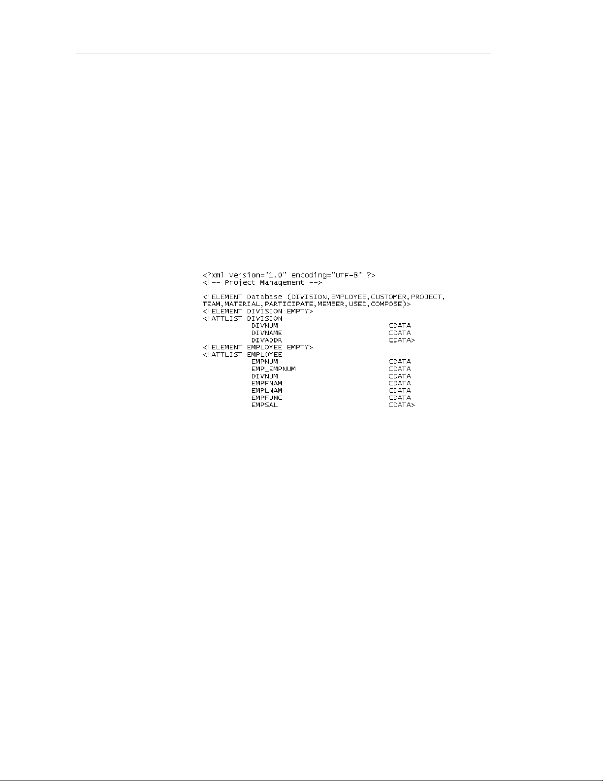
♦ A DTD file is a basic way to describe the structure of an XML
document. It is a raw list of all the legal elements making up an XML
document
Extract of a DTD file:
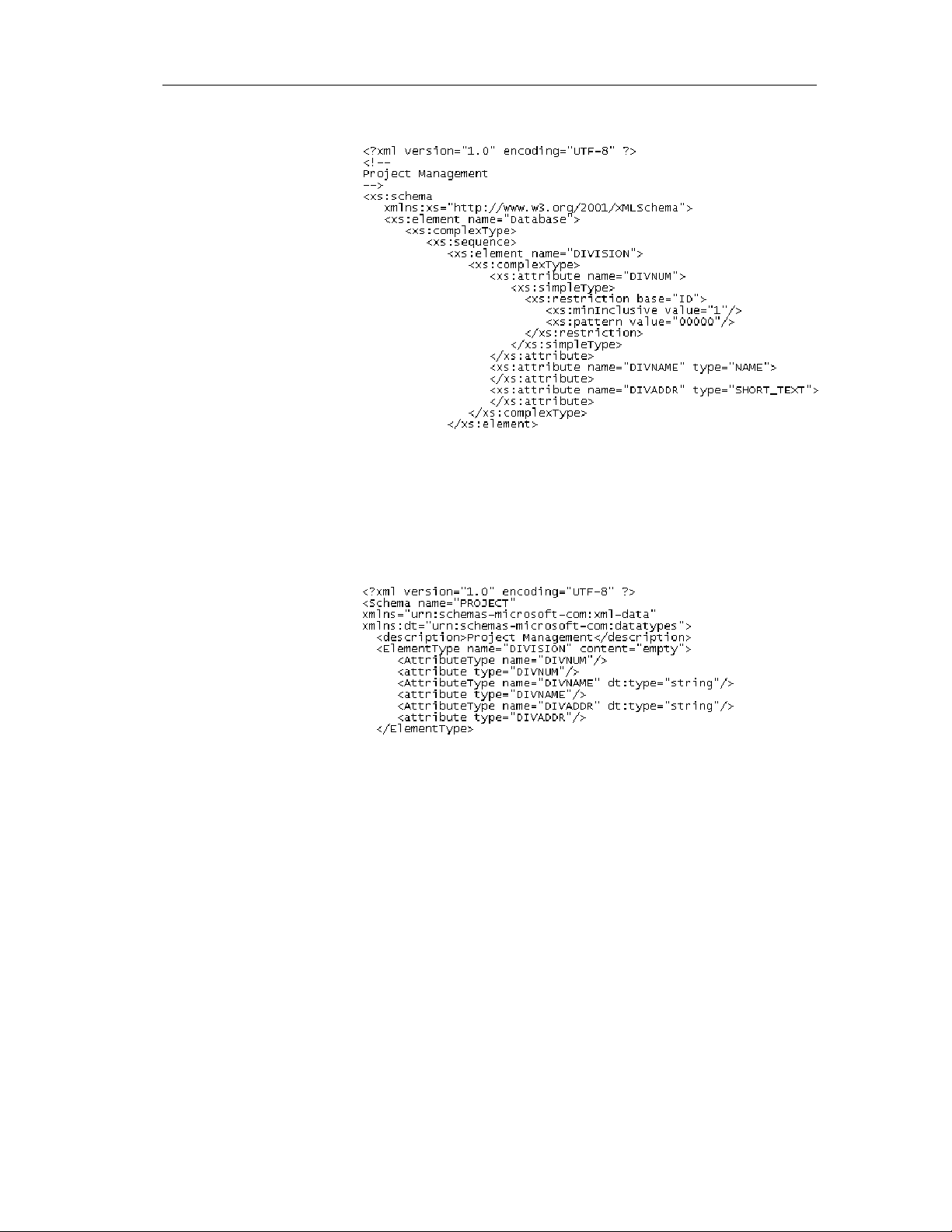
♦ An XSD file (or schema) is an elaborated way to describe the structure
of an XML document. It can support namespaces, derivations, keys,
simple and complex user-defined data types and a robust collection of
predefined data types
4 PowerDesigner
Page 17
Chapter 1 XML Model Basics
Extract of an XSD file:
An XSD file always starts with the <schema> tag (root element). All
objects created in the model will appear in the XSD file between the
schema start-tag and end-tag
♦ An XDR file is a simplified XSD file (or schema). It does not support
simple and complex user-defined data types
Extract of an XDR file:
An XDR file always starts with the <schema> tag (root element). All
objects created in the model will appear in the XDR file between the
schema start-tag and end-tag
Objects in an XML model
An XML model represents the structure of a potential or existing XML
document through a n XSD, a DTD o r an XDR file.
XSM User's Guide 5
Page 18
What is an XML model?
An XML model is a tree structure of child elements attached to parent
elements. Elements are the basic describing items of an XML model. They
can be made of other elements combined in different ways through group
particles. Elements are specified by attributes and data types which can be
predefined or user-defined. Simple and complex data types can be defined as
global (directly linked to the <schema> tag) or local (embedded in an
element declaration).
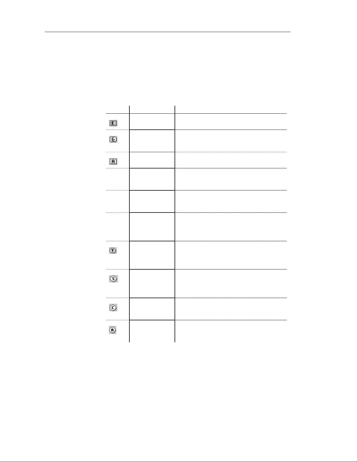
The following table displays the specific objects of an XML model:
Tool Object Description
Element The basic object of an XML model. An element
can contain other elements or attributes
Group A group of elements arranged by a group particle.
A group is defined once and reused elsewhere in
the model through references
Any Any type of object. Any can only be attached to a
sequence or a choice group particle
— Attribute Additional information about an element or a
complex type. An attribute is defined by a built-in
data type or a simple data type
— Attribute Group A group of attributes. An attribute group is
defined once and reused elsewhere in the model
through references
— Simple Type A simple data type. A simple type is used in the
case of elements or attribut es with text-only
content. Only available in a model targeted with
XSD
Complex Type A complex data type. A complex type is used to
introduce elements or attributes within an element
declaration. Only availab le in a model targeted
with XSD
Sequence A group particle to arrange a set of elements. A
sequence group particle indicates that elements
must appear at least once in t he order of their
declaration
Choice A group particle to arrange a set of elements. A
choice group particle indicates that one element
must be chosen among all elements
All A group particle to arrange a set of elements. An
all group particle indicates that each element can
appear once or not, in any order
6 PowerDesigner
Page 19
Chapter 1 XML Model Basics
Tool Object Description
— Notation A notation is used to define and process non-
XML objects within an XML model
These tools are available in the palette of the diagram window.
The main objects of an XML model are represented by symbols in its
diagram.
Objects in a diagram
Some objects may not appear in a diagram because they do not have a
symbol or this symbol has been deleted or hidden.
Always check the existence of objects in the Browser tree view.
Example of an XML diagram:
You can use several diagrams to have partial views of a complex diagram.
XSM User's Guide 7
Page 20
What is an XML model?
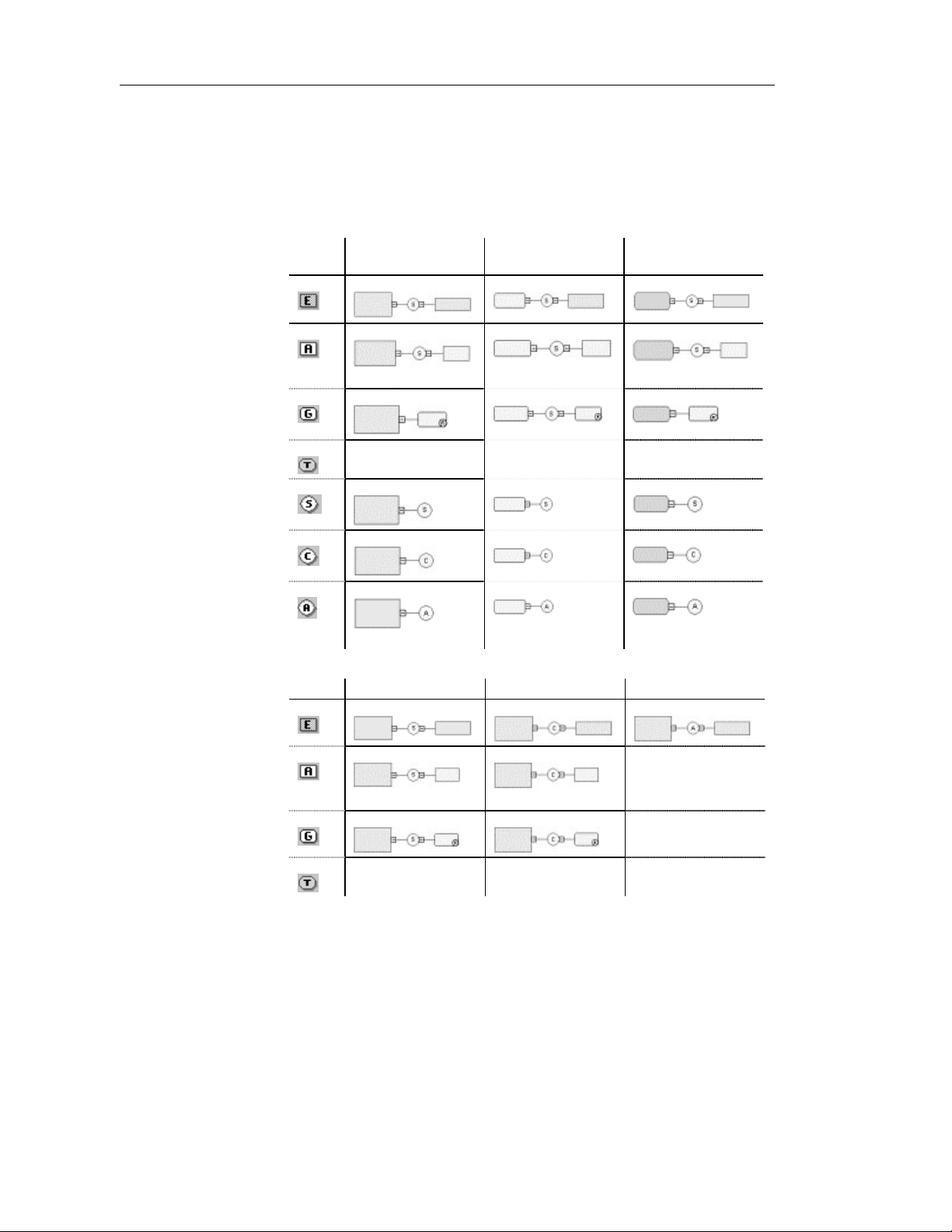
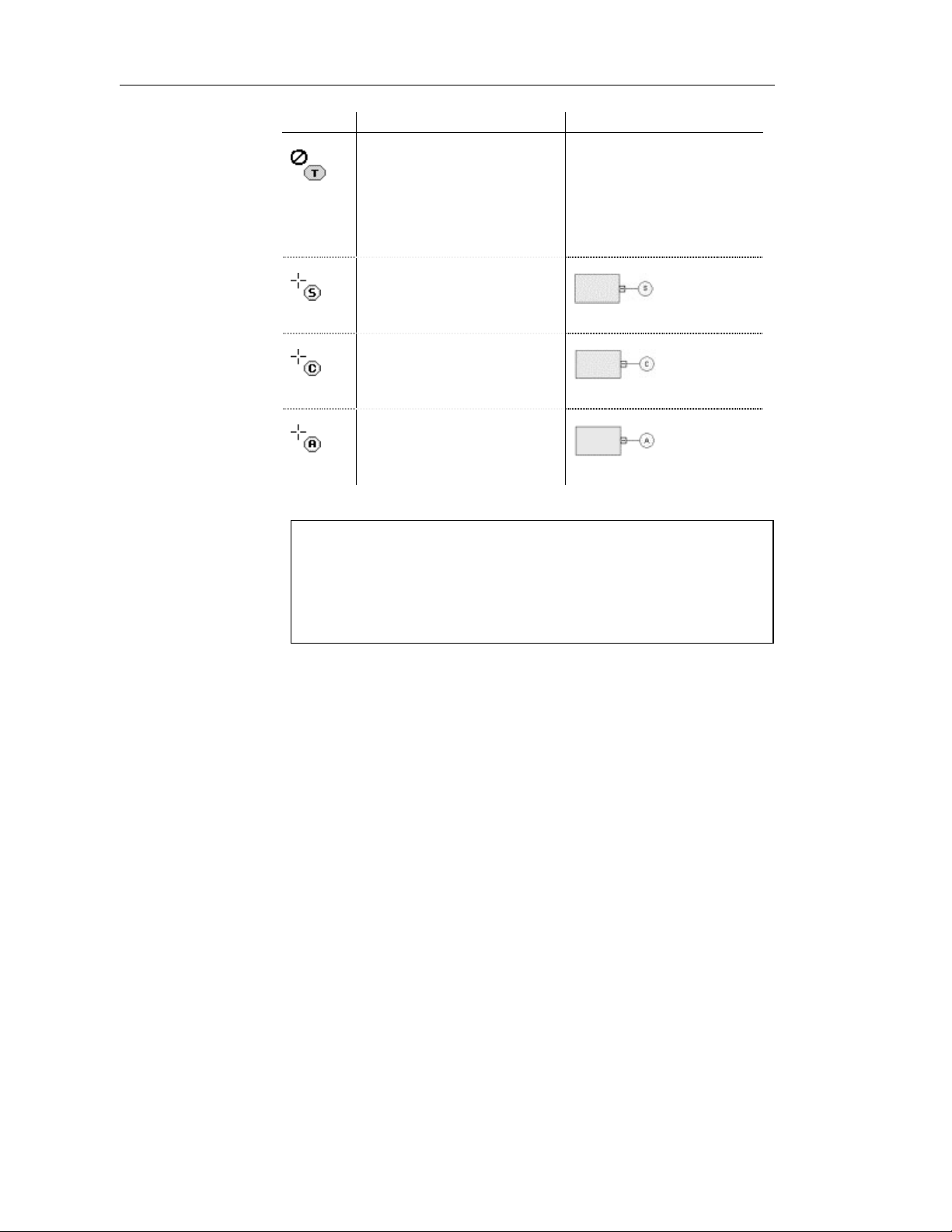
How to link a child object to a parent object in an XML model?
XML objects do not support standard link objects. To link a child object to a
parent object, you must click the child object tool in the palette and then click
the symbol of the parent object in the diagram. This will automatically create
a link between both objects. See the following table for allowed links:
Complex type
Tool Element symbol Group symbol
Any
No link No link No link
symbol
All
Tool Sequence symbol Choice symbol All symbol
No link
Any
No link
No link No link No link
8 PowerDesigner
Page 21
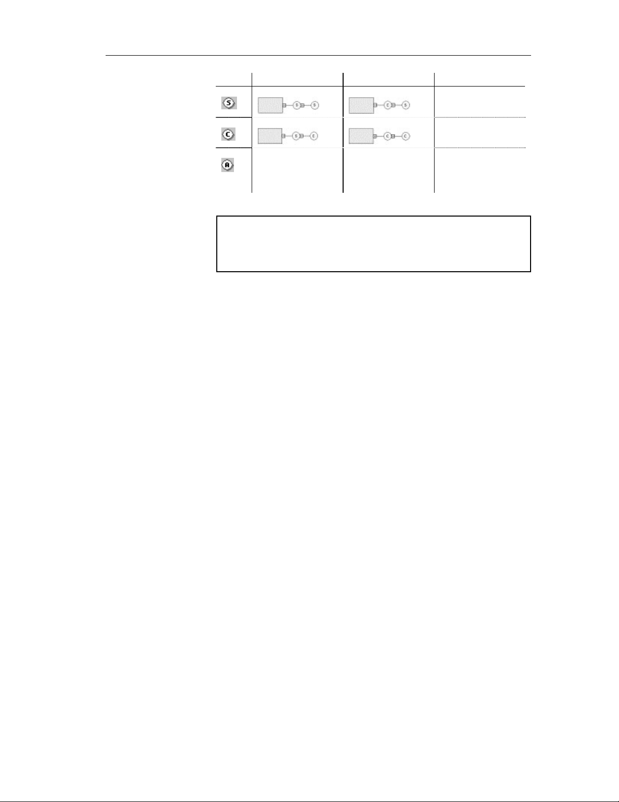
Chapter 1 XML Model Basics
Tool Sequence symbol Choice symbol All symbol
No link
No link
No link No link No link
All
Caution
A group particle (sequence, choice, all) cannot be created from scratch in
a diagram.
It must be the child element of an element, a group or a complex type.
For more information, see sections How to link a child object to an
element, How to link a child object to a group particle, How to link a child
object to a group of elements, How to link a child object to a complex type,
in chapter Building an XML model.
XSM User's Guide 9
Page 22

Defining the XML model environment
Defining the XML model environment
The XML model environment includes a set of parameters and configuration
options that define various aspects of the model content and behavior. You
can set these parameters:
♦ At model creation
♦ After creating a model with default options and parameters
♦ When creating a model template
Choosing the XML language of an XML model
An XML language contains specifications for a partic ular language. It
provides PowerDesigner with the syntax and guidelines for implementing
stereotypes, d ata types, scripts and constants for an XML la nguage. You
manage an XML language from the Resource Edi tor. The langua ge displays a
tree view with several categories that can be used to extend XML model
objects (Profile category) or manage generation (Generation category).
Each XML model is by default attached to an XML language. When you
create a new XML model, you must choose an X ML language. You can
create a new XML language or use the XM L l anguages delivered with
PowerDesigner.
The definition of an XML language is available from its property sheet. You
can select and configure parameters used when defining objects or generating
from an XML model.
For more information on XML language s, see chapter XML Languages
Reference Guide in the Advanced User Documentation.
For more information on resource files, see chapter The Resource
Editor in the General Features Guide.
Not certified resource file
Some resource files are delivered with "Not Certified" in their names.
Sybase will perform all possible validation checks, however Sybase does
not maintain specific environments to fully certify these resource files.
Sybase will support the definition by accepting bug reports and will
provide fixes as per standard policy, with the exception that there will be
no final environmental validation of the fix. Users are invited to assist
Sybase by testing fixes of the definition provided by Sybase and report
any continuing inconsistencies.
10 PowerDesigner
Page 23

Changing the XML language of an XML model
If you change the XM L language of an XML model, you have to define the
status of the language:
XML
language Description
Share To use the shared XML language stored in the XML Languages
directory of your installation. Any changes made to the XML
language are available to the linked XML model
Copy To create a copy of the XML language in the model. The current
XML language is independent from the original XML language,
so any changes made in the XML language are not available to
other models. The XML language is saved with the model and
cannot be used by other models
Caution
PowerDesigner is delivered with a set of XML languages. It is strongly
advised to make a backup copy of each XML language before you start
modifying them.
Chapter 1 XML Model Basics
To change the XML language of an XML model:
1 Select Language→Change Current Language.
The Change XML La nguage dialog bo x appears.
2 Select an XML langua ge.
3 Select the Share or Copy radio button.
XSM User's Guide 11
Page 24
Defining the XML model environment
4 Click OK.
A message box informs you that the current XML language has been
changed.
5 Click OK.
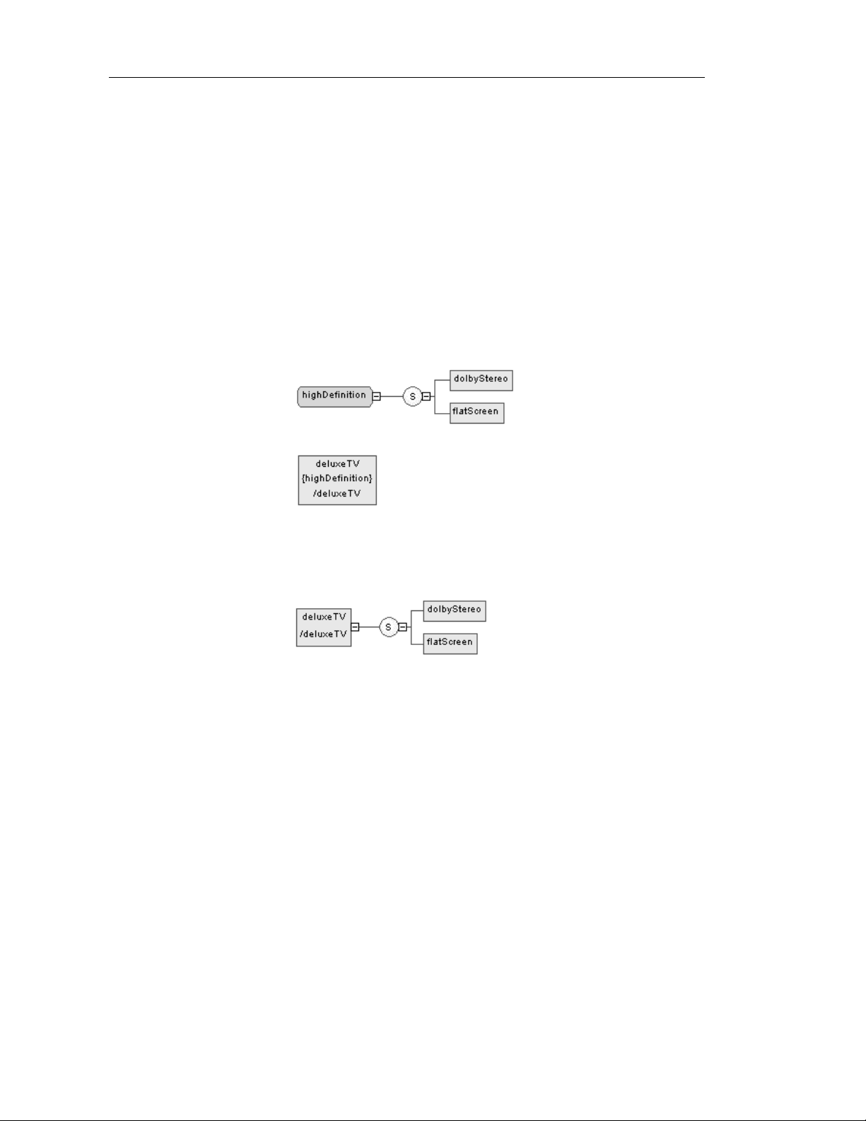
Changes concerning simple and complex types
Simple types and complex types are only supported by XSDs (schemas).
When changing an XSD into a DTD or an XDR, simple types and global
complex types (directly linked to the <schema> tag) disappear from the
diagram and the Browser tree view. Local complex types (within an element)
are expanded in the diagram, beneath their containing element.
♦ Example of a complex type with XSD:
HighDefinition is a global complex type, reused as data type for the
deluxeTV element.
♦ The same example with DTD or XDR:
For more information on simple and complex types, see sections
Defining simple types and Defining complex types in chapter Building
an XML model.
12 PowerDesigner
Page 25
Chapter 1 XML Model Basics
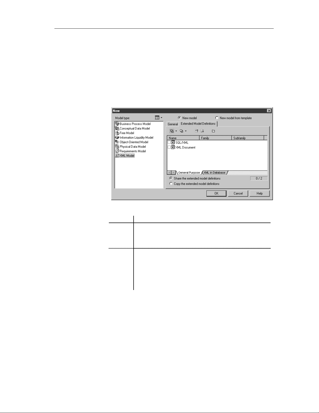
Selecting extended model definitions at model creation
Extended model definitions (.XEM files) provide means for customizing and
extending PowerDesigner metaclasses, parameters and generation. Extended
model definitions are typed like models in PowerDesigner. You create an
extended model definition for a specific type of model and you cannot share
these files between heterogeneous models.
When you create a new XML model, or when you reverse engineer into a
new XML model, you can select one or several extended model definitions
and attach them to the model from the New dialog box.
You can choose one of the following options:
Option Description
Share Current extended model definition constantly refers to the extended
model definition stored in the Resource Files\Extended Model
Definitions directory. Any changes made to the extended model
definition are shared by all linked XEM
Copy Current extended model definition is a unique copy of the extended
model definition stored in the Resource Files\Extended Model
Definitions directory. The current extended model definition is
independent of the original one, so modifications made to the
extended model definition in the Resource Files\Extended Model
Definitions directory are not available to the copied XEM. This one
is saved with the XML model and cannot be used without it
XSM User's Guide 13
Page 26

Defining the XML model environment
For more information on extended model definitions, see chapter
Extended Model Definitions Reference Guide, in the Advanced User
Documentation.
Defining model options
Name/Code case
sensitive
Enable links to
requirements
Naming
conventions
You can define the case sensitivity of names and codes for all objects in the
current model. When this check box is selected, it implies that you can have
two objects with identical name or code but different case in the same
namespace.
Unlike other model options, you can modify the name and code case
sensitivity during the design process. However, if you do so, make sure you
run the check model feature to verify if the model does not contain any
duplicate object.
Requirements are descriptions of customer needs that must be satisfied
during development processes.
You can enable links to requirements for all objects in the current model.
When this check box is selected, it implies that the Requirements tab
appears in the objects property sheet. The Requirements page allows you to
attach requirements to objects; these requirements are defined in the
Requirements models open in the workspace. Attached requirements and
Requirements models are synchronized.
For more information on requirements, see the Requirements Model
User’s Guide.
You can also set naming conventions for each type of objects in your model.
For information on naming conventions, see section Defining naming
conventions, fr om chapter Managing Models, in the General Features Guide.
14 PowerDesigner
Page 27
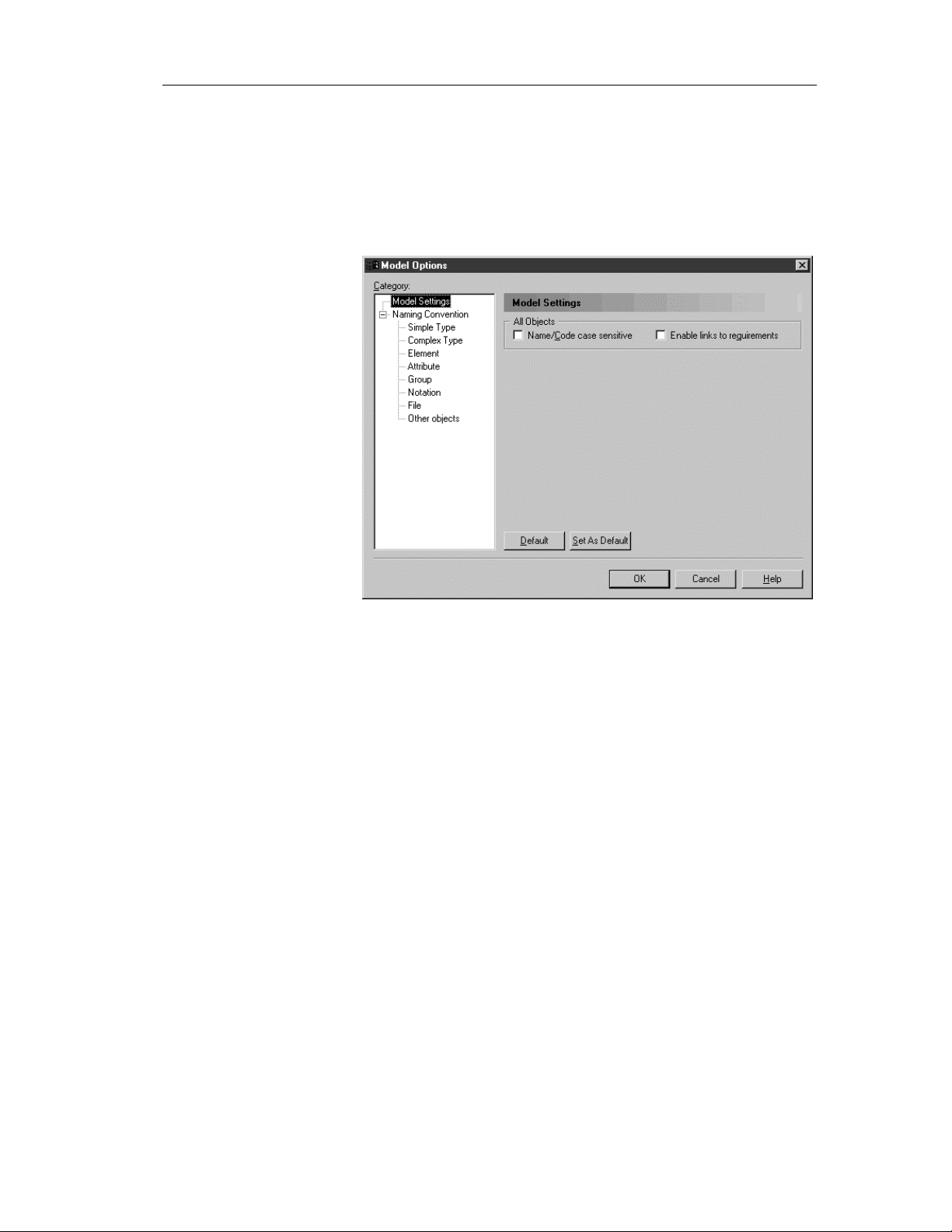
To define XML model options:
1 Select Tools→Model Options.
or
Right-click the diagram background and select Model Options in the
contextual menu.
The Model Options dialog box opens to the Model Settings pane.
Chapter 1 XML Model Basics
2 Select or clear the Name/Code case sensitive check box in the All
Objects groupbox.
3 Click OK.
XML model extended dependencies
Extended dependencies are links between objects of an XML model. These
links help to make object relationships clearer but are not interpreted and
checked by PowerDesigner as they are meant to be used for documentation
purposes only.
You can complement these links by applying stereotypes. Stereotypes can be
used to define extended dependencies between objects in an XML model.
XSM User's Guide 15
Page 28

Defining the XML model environment
You can type stereotypes directly in the Stereotype column of the object
property sheet or select a value from the dropdown listbox if you have
previously defined stereotypes in an embedded or imported extended model
definition (.XEM).
For more information on extended model definitions, see chapter
Extended Model Definitions Reference Guide in the Advanced User
Documentation.
16 PowerDesigner
Page 29
Defining an XML model
This section presents the main operations you have to perform before starting
to build or work on an XML model.
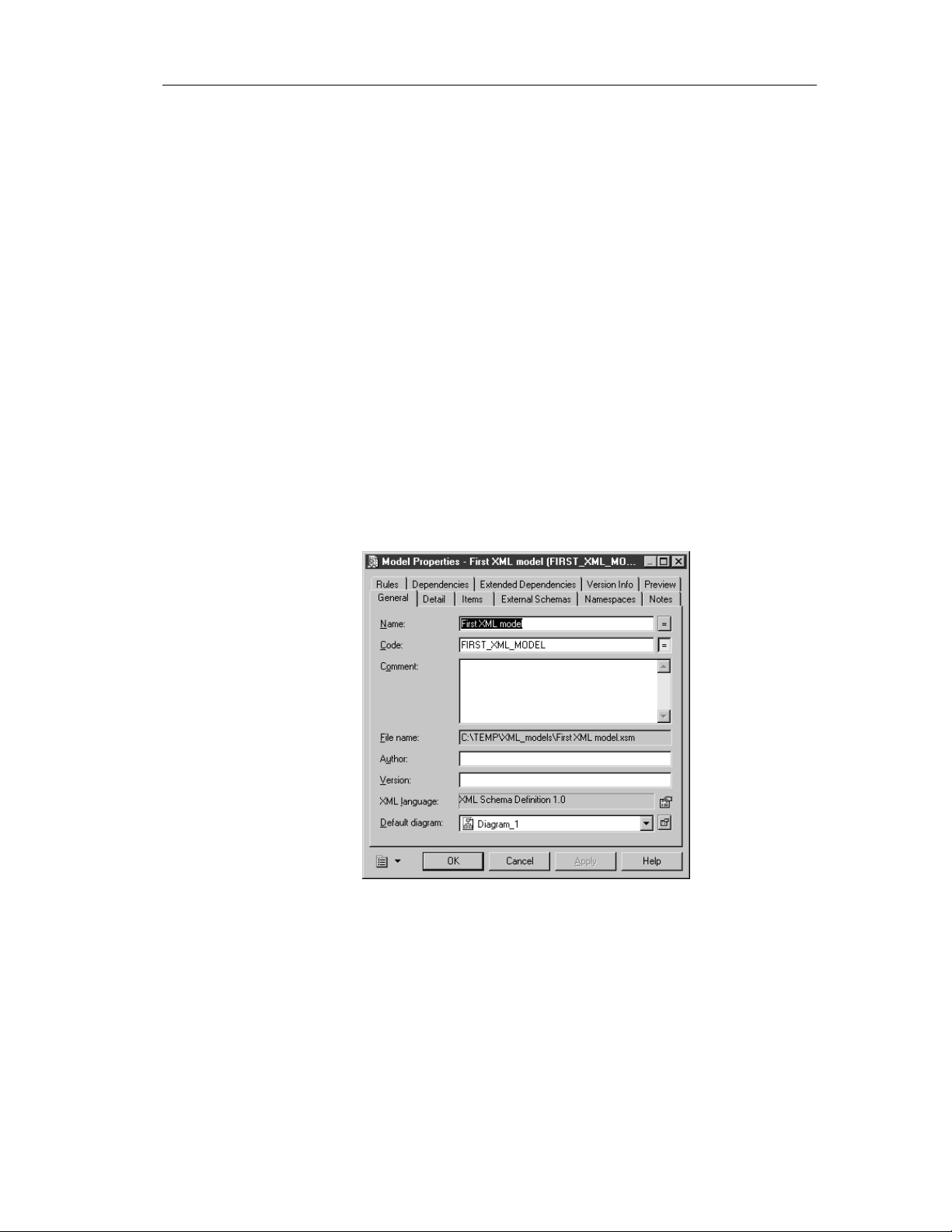
Defining model properties
The model property sheet displays the definition of the current model.
Only the specific pages of an XML model are explained in this section.
For information on the generic pages of a model property sheet, see
section Using property sheets in chapter Using the PowerDesigner
Interface in the General Features Guide.
To define the properties of an XML model:
1 Select Model→Model Properties.
or
Right-click the diagram background and select Prop erties from the
contextual menu.
Chapter 1 XML Model Basics
The model property sheet appears.
2 Type changes to model properties in the different pages.
XSM User's Guide 17
Page 30

Defining an XML model
Model General page
If you want to display the XML language, click the Properties t ool
beside the XML language box in the Ge neral page to display the
property sheet of the XML language .
3 Click OK.
The General page of the model property sheet displays the following
properties:
Property Description
Name The name of the item which should be clear and meaningful,
and should convey the item's purpose to non-technical users
Code The technical name of the item used for generating code or
scripts, which may be abbreviated, and should not generally
include spaces
Comment Descriptive label of the model
File name Location of the model file. This box is empty if the model has
never been saved
Author Author o f the model. You can insert a name, a space or
nothing. If you insert a space, the Author field in the title box
remains empty. If you intentionally leave the box empty, the
Author field in the title box displays the user name from the
Version Info page of the model property sheet
Version Version of the model. You can use this box to display the
repository version or a user-defined version of the model.
This parameter is defined in the display preferences of the
Title node
XML language Current XML language for the model
Default diagram Diagram displayed by default when opening the model
18 PowerDesigner
Page 31

Model Detail page
Chapter 1 XML Model Basics
The Detail page of a model property sheet (only available in a model targeted
with XSD) displays the following properties:
Property Description
Target
Namespace
Language Indicator of the language used in the model. For example: en,
ID ID of the model. Its value must be of type ID and unique
Element Form Form of the elements declared in th e target namespace. If you
Namespace of all the model objects. Its name is a URI which
does not refer to any file but only to an assigned name. A
prefix can be assigned to the namespace. All the schema
elements with this prefix in their start-tag will be associated
with the namespace. For example:
http://www.mycompany.com/myproduct/XMLmodel
en-GB, en-US, de, fr
within the file containing the model. For example: XMOD1
select Qualified, elements must be qualified with the
namespace prefix. If you select Unqualified, el ement s are not
required to be qualified with the namespace prefix. The value
of Element Form is the global default value for all the
elements declared in the target namespace. To override this
setting, individual elements can use the Form attribute
Attribute Form Form of the at t r ibutes declared in the target namespace. If you
select Qualified, attributes must be qualified with the
namespace prefix. If you select Unqualified, attributes are
not required to be qualified with the namespace prefix. The
value of Attribute Form is the global default value for all the
attributes declared in the target namespace. To override this
setting, individual attributes can use the Form attribute
Block Default value for th e Bl ock property of elements and complex
types in the target namespace. The Block property prevents an
element or a complex type with a specified t ype o f derivation
from being used in place of the inherited element o r complex
type
Final Default value for the Final property of elements, simple types
and complex types in the target namespace. The Final
property prevents the specified type of derivation for an
element, a simple type or a complex type
For more information on elements, attributes, simple and complex
types, see chapter Building an XML model.
XSM User's Guide 19
Page 32

Defining an XML model
Model Items page
The Items page of the model property sheet displays the list of global objects
(with no parent symbol in the diagram, directly linked to the <schema> tag)
created in the model. This list reflects the order in which global objects are
being declared in the schema. If you want to change this order of declaration,
you must select an item in the list and use the arrowed buttons, at the bottomleft corner of the page, to move the selected item in the list:
Button Moves item
Top of the list
Up one page
Up one line
Down one line
Down one page
Bottom of the list
You can also use the Items page to create global objects in the model:
Tool Tooltip Description
Add Element Adds an element to the model
Add Group Adds a group of elements to the model
Add Attribute Adds an attribute to the model
Add Attribute Group Adds a group of attributes to the model
Add Simple Type Adds a simple type to the model. Only
available in a model targeted with XSD
Add Complex Type Adds a complex type to the model. Only
available in a model targeted with XSD
Add Notation Adds a notation to the model, to describe the
format of non-XML data
20 PowerDesigner
Page 33

Tool Tooltip Description
For more information on these items, see chapter Building an XML
model.
Model External Schemas page
A schema is an XML-written text defining the content and structure of an
XML document. An XML model is a graphic representation of a schema.
You can use the following tools to reuse in your model global objects from
other schemas:
Tool Tooltip Description
Chapter 1 XML Model Basics
Add Annotation Adds an annotation to the model, to provide
documentation or application information.
Only available in a model targeted with XSD
Add Include Adds a specified schema file to be included in the
target namespace of the current schema
Add Import Adds a specified namespace whose schema
components are referenced by the current schema
Add Redefine Adds a specified schema file whose simple and
complex types, groups and attribute groups can be
redefined in the current schema
Add Annotation Adds an annotation to the model to provide
documentation or application information
For more information on these items, see chapter Building an XML
model.
XSM User's Guide 21
Page 34

Defining an XML model
Model Namespaces page
A namespace is a URI indicating a location where objects are declared. The
prefix of a namespace, followed by a colon (:) and the name of an object,
indicates that this object is declared in that namespace. Namespaces are not
supported by DTDs.
You can use the following tools to attach namespaces from other models or
schema files to the current model:
Tool Tooltip Description
Add Namespaces
from XML Models
Adds namespaces of other XML models. These
are source namespaces for the current model
Add Namespaces
from XML schema
files
Adds namespaces of other schema files
available on your machine. Th ese are source
namespaces for the current model
♦ In the case of a model targeted with XSD, the namespace of the W3C
XML Schema Recommendation is predefined in the list of namespaces.
22 PowerDesigner
Page 35

Chapter 1 XML Model Basics
♦ In the case of a model targeted with XDR, two namespaces are
predefined in the list of namespaces.
XSM User's Guide 23
Page 36

Defining an XML model
Model Preview page
The Preview page of the model property sheet displays a preview of the
XSD, DTD or XDR file generated from the XML model.
Example of an XSD file (or schema file):
The schema file starts with the XML declaration followed by the <schema>
(root element) declaration.
All objects created in the model will appear in the schema file between the
schema start-tag and end-tag.
Creating an XML model
There are several ways to create an XML model:
♦ Create a new XML model
♦ Create a new XML model using a template
♦ Create an XML model using existing elements (reverse engineering an
XSD, a DTD or an XDR file, generating from a PDM or an OOM)
24 PowerDesigner
Page 37

Creating an XML model using the New model option
When you create a new XML model using the New model option, you have
to select an XML language.
You can then select one of the following options:
Option Description
Share To use the shared XML language stored in the XML Languages
directory of your installation. Any changes made to the XML
language are available to the linked XML model
Copy To create a copy of the XML language in the model. The current
XML language is independent from the original XML language, so
any changes made in the XML language are not available to t he
other models. The XML language is saved with the model and
cannot be used by other models
To create a new XML model using the New model option:
1 Select File→New to display the New dialog box.
Chapter 1 XML Model Basics
2 Select XML Model in the list of model types.
3 Select the New model radio button in the upper right part of the dialog
box.
4 Select an XML langua ge from the XML language dropdown listbox of
the General page.
5 Select either Share or Copy.
XSM User's Guide 25
Page 38

Defining an XML model
6 <optional> If you want to attach one or more extended model definitions
to the model, click the Extended Model Definitions tab, and select the
extended model definitions of your choice.
For more information on attaching extended model definitions to a
model, see section Selecting extended model definitions at model
creation.
7 Click OK.
A new XML model is created in the Workspace.
8 Select Model→Model Properties.
or
Right-click any empty space in the diagram window and select
Properties from the contextual menu.
The model property sheet appears.
9 Type a name and a code for the model.
10 Click OK.
26 PowerDesigner
Page 39

Chapter 1 XML Model Basics
Creating an XML model using the New model from template option
To create a new XML model using the New model from template
option:
1 Select File→New to display the New dialog box.
2 Select XML Model in the list of model types.
3 Select the New model from template radio button in the upper right part
of the dialog box to display the Template page.
4 Select a model template from the list.
List of templates
You can select user-defined model templates (use the Change UserDefined Model Templates Folder tool to specify the user templates
folder) and copy some existing models as model templates using the
Copy Model to User-Defined Model Templates Folder tool.
For more information on model templates, see section Creating a
model in chapter Managing Models, in the General Features Guide.
5 Click OK.
A new XML model is created in the Workspace.
6 Select Model→Model Properties.
or
Right-click any empty space in the diagram window and select
Properties from the contextual menu.
The model property sheet appears.
7 Type a name and a code for the model.
8 Click OK.
XSM User's Guide 27
Page 40

Defining an XML model
Opening an existing XML model
An XML model has the file extension .XSM.
Choose XML
language
If PowerDesi gner cannot find the XML language attached to the XML model
you want to open, the Choose XML Language dialog box appears to let you
select another XML language to attach to the model. You can select the XML
language from the XML language dropdown listbox.
To open an existing XML model:
1 Select File→Open.
or
Click the Open tool.
A standard Windows Open file dialog box appears.
2 Select a file with an .XSM extension.
3 Click Open.
The model opens in the diagram window and appears in the Browser.
Detaching an XML model from the workspace
When you detach an XML model from a workspace, its node is removed
from the Browser and it is no longer defined in the workspace. Yet the file is
not deleted from your operating environment.
To detach an XML model from a workspace:
1 Right-click the XML model node in the Browser and select Detach from
Workspace in the contextual menu.
A confirmation box asks if you want to save the XML model.
2 Click Yes if you want to save modifications to the XML model.
Select or browse to a directory.
Type a name for the file and click the Save button.
or
Click No if you do not want to save modifications to the file.
The XML model is removed from the workspace.
28 PowerDesigner
Page 41

Saving and closing an XML model
Chapter 1 XML Model Basics
Saving an XML
model
Closing an XML
model
To save an XML model, choose one of the following options:
♦ Select File→Save
♦ Click the Save tool in the standard toolbar
♦ Right-click the XML model in the Browser tree view and select Save in
the contextual menu
If it is the first time you save an XML model, a standard Windows Save As
dialog box appears: Type a file name, choose a folder in your directory and
click Save.
To close an XML model, choose one of the following options:
♦ Select File→Close
♦ Right-click the XML model in the Browser tree view and select Close in
the contextual menu
When an XML model is closed, a red mark appears on its icon in the
Browser tree view:
XSM User's Guide 29
Page 42

Defining an XML model
30 PowerDesigner
Page 43

CHAPTER 2
Building an XML model
About this chapter
Contents
This chapter describes how to build an XML model (XSM). It explains the
role of each object in an XML model and how to create and modify them.
Topic Page
XML diagram basics 32
Defining elements 35
Defining identity constraints 64
Defining groups 76
Managing external shortcuts through references and data types 87
Defining simple types 89
Defining complex types 92
Defining derivations 102
Defining annotations 115
Defining notations 120
Defining entities 122
Defining import, include and redefine 125
Defining business rules 132
XSM User's Guide 31
Page 44

XML diagram basics
XML diagram basics
You can create XML diagrams in an XML model.
Defining an XML diagram
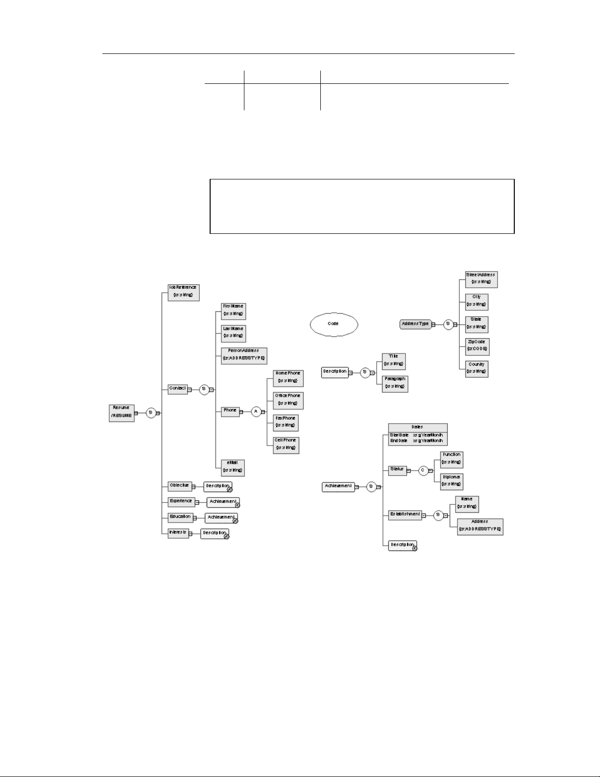
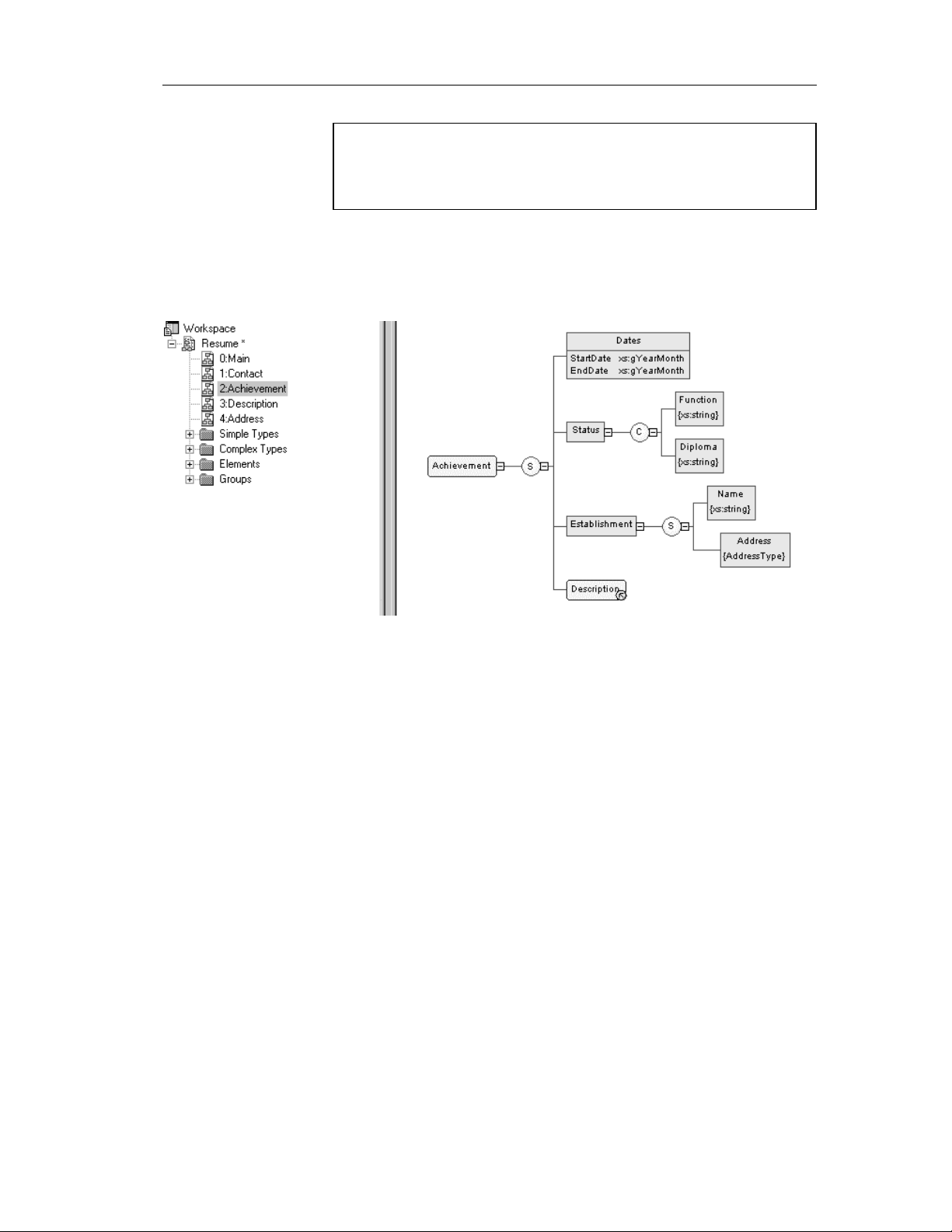
An XML diagram is a graphical view of an XML model.
The following example shows the diagram of the Resume XML model:
The main objects of an XML model are represented by symbols in its
diagram.
32 PowerDesigner
Page 45
Chapter 2 Building an XML model
Objects in a diagram
Some objects may not appear in a diagram because they do not have a
symbol or this symbol has been deleted or hidden.
Always check the existence of objects in the Browser tree view.
If an XML model is too large or too complex, you can create several
diagrams to have partial views of the model and focus on certain objects.
The following example displays the Achievement diagram of the Resume
XML model:
The original diagram of the Resume XML model being too large (see first
picture), it has been split into five diagrams (Main, Contact, Achievement,
Description and Address) corresponding to the five main objects of the
model.
Why build an XML diagram?
An XML diagram is the easiest way to define the structure and content of an
XML document if you are not familiar with the syntax of XML Schema
Definition (XSD), Document Type Definition (DTD) or XML-Data Reduced
(XDR).
With the user-friendly graphical interface of PowerDesigner XML Model,
you can build an XML diagram and then generate automatically an XSD, a
DTD or an XDR file.
XSM User's Guide 33
Page 46
XML diagram basics
Creating an XML diagram
There are two ways to create an XML diagram:
♦ From a new XML model
♦ From an existing XML model
For information on creating an XML diagram from a new XML model,
see section Creating an XML model in chapter XML Model Basics.
For information on creating an XML diagram from an existing XML
model, see section Creating a new diagram in chapter Managing Models in
the General Features Guide.
Group Symbols feature
The Symbol→Group Symbols feature is only available for free symbols in
an XML diagram.
Expand/Expand All/Collapse/Arrange Symbols features
Right-click a symbol in an XML diagram and select one of these features
in the contextual menu:
Expand: the hierarchy below a symbol is partially expanded (only the first
level).
Expand All: the hierarchy below a symbol is fully expanded (all levels).
Collapse: the hierarchy below a symbol is hidden.
Arrange Symbols: the hierarchy below a symbol is properly displayed.
34 PowerDesigner
Page 47
Defining elements
Elements are the basic building blocks of an XML model.
An XML model is a tree structure of elements where child elements are
attached to parent elements.
For example (Browser tree view and diagram):
Chapter 2 Building an XML model
XSM User's Guide 35
Page 48

Defining elements
Generated schema:
In a schema, elements are declared with <element> tags.
Defining element properties
To display an element property sheet, double-click its symbol in a diagram.
36 PowerDesigner
Page 49

Element general properties
There are global and local elements:
♦ Global elements have no parent element in a diagram. They are directly
linked to the <schema> tag (root element) in a schema. They can be
reused in the mod el through refere ncing elements (See
“XML_declaration” in the Defining elements example)
♦ Local elements have a parent element in a diagram. They are unique
within their parent scope. They can be defined by reference to a global
element (See Reference in the following table)
Global and local elements in XDR files
In a model targeted with the XML-Data Reduced language, local elements
are first declared separately, like global elements (with the
<ElementType> tag and a name attribute), then within their parent element
(with the <element> tag and a type attribute).
Extract of an XDR file:
Chapter 2 Building an XML model
Parent ele ments are linked to the i r child elements through group particles
(sequence, choice or all). A parent element can contain a group of child
elements (See Group type in the following table)
You can derive an element data type to extend or restrict its values. (Only
with a model targeted with XSD)
The General page of an element property sheet displays the following
properties:
Property Description
Name The name of the item which should be clear and meaningful,
and should convey the item's purpose to non-technical users
Code The technical name of the item used for generating code or
scripts, which may be abbreviated, and should not generally
include spaces
Comment Descriptive label of the element
Stereotype Sub-classification used to extend the semantics of an object
without changing its structure. It can be predefined or user-
defined
XSM User's Guide 37
Page 50

Defining elements
Property Description
Reference Name of a global element. The current element will have the
same properties as the global el ement. The Reference property
is only available for child elements. Use the dropdown listbox
to select a global element in the current model. Use the Browse
tool to select a global element from any model opened in the
current workspace. If you select a global element from another
model, a shortcut is creat ed with the referencing element. When
you define a reference, name and code properties are grayed.
Name and code are those of th e global element
Group type Indicator that specifies how child elements are to be used
within the parent element. It can be a group particle (all,
choice, sequence) or a group of elements (group). If you select
group, a referencing group is directly linked to the current
element (see Defining group properties)
Type Element data type. Use the dropdown listbox to select a built-in
data type. Use the Browse tool to select a simple or a complex
type from any model opened in the current worksp ace. In the
case of an XSD, selecting a data type will delete any group
particle (and its child elements) or attribute previously defined
in the element propert y sheet. Do not select a data type if you
want to define attributes or child elements within the current
element
Embedded type Locally defined data type. It applies to the current element only.
Automatically set to Complex if you define a derivation for the
element data type. Only available in a model targeted with XSD
Content
Derivation Derivation method for the element data type. Used to extend or
Content type of the element. If you select Complex, the
element can have child elements. If you select Simple, the
element cannot have child elements. Only available in a model
targeted with XSD
restrict the values of the element data type. When you define a
derivation, the data type disappears. You must click Apply and
then the Properties tool to select a base type in the derivation
property sheet. Only available in a model targeted with XSD
For more information on group particles, see section Linking child
elements to a parent element.
For more information on derivations, see section Defi ni ng derivations.
Once you have defined the reference of a referencing element, you can locate
the referenced element in the diagram by right-clicking the referencing
element symbol and selecting Find Referenced Element in the contextual
menu. The referenced element appears with handles in the diagram.
38 PowerDesigner
Page 51

Chapter 2 Building an XML model
Defining elements
in XDR files
In a model targeted with the XML-Data Reduced language, elements are
defined by different attributes:
Property or page
XDR attribute
for an element Description
Model
Content
Order
To specify if a global element can
contain new local element s. Set to
closed by default. Set to open if an
Any symbol is attached to the element
symbol
To specify the content of a glo bal
element. If a group particle and a data
type are defined, the content value is
mixed. If a group particle and no data
type is defined, the content value is
eltOnly. If no group particle and a
data type is defined, the content value
is textOnly. If no group particle or
data type is defined, the content value
is empty
To specify how local elements are
organized within a global element.
Set to seq for a sequence group
particle. Set to one for a choice group
particle. Set to many for an All group
particle
in element
property sheet
—
Group type, Type
Group type
dt:type
dt:values
type
minOccurs
maxOccurs
XSM User's Guide 39
To specify a data type for a global
element
To specify a list of available values
for a global element
To specify the name of a global
element as reference for a local
element
To specify the minimum number of
occurrences for a local element.
Usually set to 0 or 1
To specify the maximum number of
occurrences for a local element.
Usually set to 1 or * (unbounded)
Type
Values page
Reference
Detail page in local
element property
sheet
Detail page in local
element property
sheet
Page 52

Defining elements
Example of an XDR file:
Element detail properties
The Detail page of an element property sheet displays the following
properties:
Property Description
Minimum Mini mum number o f times the element can occur. To
Maximum Maximum number of times the element can occur. For an
Substitution group Name of a global element for which the current element can
specify that the element is opti onal, set this attribute to zero
unlimited number of times, select unbounded
be substituted. It must have the same type or a derived type.
Its value must be a qualified name (See Glossary)
Default Default value of the element if its content is a simple type
or text-only. Enter a default value only if there is no fixed
value
Fixed Predetermined, unchangeable value of the element if its
content is a simple type or text-only. Enter a fixed value
only if there is no default value
Block Property to prevent another element with the same type of
derivation from being us ed in place of the current element
Final Property to prevent derivation of the current element.
Prohibited if the element is not a glo bal element
Form Form of the element. Used to specify the target namespace
of the element. If you select Qualified, a namespace prefix
is required to qualify the element. If you select
Unqualified, a namespace pr efix is not required to qual i fy
the element
ID ID of the element. Its value must be of type ID and unique
within the model containing the element
Abstract Property defining if the element can appear in the instance
document or not. If selected, the element cannot appear in
the instance document
40 PowerDesigner
Page 53

Property Description
Nillable Property defining if the element is null or not
In the case of a model targeted with XDR, the Detail page is only available
for local elements.
Element attributes properties
Attributes give additional information about an element.
The Attributes page of an element property sheet allows you to add attributes
to an element declaration:
Tool Tooltip Description
Chapter 2 Building an XML model
Add Attribute Creates a local attr i bute
Add Attribute Group with
Reference to Attribute
Group
Add Attribute with
Reference to Attribute
from a Selection
Add Attribute Group with
Reference to Attribute
Group from a Selection
Any Attribute Adds any attribute of a specified
Adds an attribute group with a reference
to an attribute group defined in the current
model. Select a name in the Reference
dropdown listbox. You can also type a
new name in the Reference column and
then define a new attribute group in the
Attribute Groups list (See Model menu)
Adds one or several attributes with a
reference to global attributes defined in
the current model. Select one or several
global attributes in the Selection dialog
box
Adds one or several attribute groups with
a reference to attribute groups defined in
the current model. Select one or several
attribute groups in the Selection dialog
box
namespace
You can access directly to the Attributes page of an element property sheet
through the contextual menu. Right-click an element symbol in the diagram
and select Attributes in the contextual menu.
XSM User's Guide 41
Page 54

Defining elements
Element constraints properties
Identity constraints allow you to indicate that element values must be unique
within their specified scope.
You can use the Constraints page of an element property sheet to add the
following constraints to an element declaration:
Tool Tooltip Description
You can access directly to the Constraints page of an element property sheet
through the contextual menu. Right-click an element symbol in the diagram
and select Constraints in the contextual menu.
Key Constraint The element value must be a key within the
specified scope. The scop e of a key is the
containing element in an instance document. A
key must be unique, not null, and always
present
Unique Constraint The element value must be unique or null
within the specified scope
KeyRef Constraint The element value corresponds to those of the
specified key or unique constraint
For more information on constraints, see section Defining identity
constraints.
Element mapping properties
Object mapping is the ability to establish a correspondence between objects
belonging to het erogeneous models a nd diagrams.
The Mapping page of an element property sheet allows you to map the
current element and its attributes to PDM or OOM objects.
Select a data source in the Mapping for dropdown listbox. If it is the first
time you define a mapping for an element, the Mapping for dropdown listbox
is empty. Click the Add a Mapping for a Data Source tool and select a data
source.
Element Sources
page
42 PowerDesigner
The Element Sources page allows you to associate one or several PDM or
OOM objects to the current element.
You can use the Add Objects tool to select objects from the PDMs or OOMs
opened in the current workspace.
Page 55

Chapter 2 Building an XML model
Attributes Mapping
page
The Attribut es Mapping page allows you to define the mapping between
PDM columns or OOM class attributes and the element attributes.
Tool Tooltip Description
Add Mapping Use this tool to select the attributes in the
current element that will be mapped to PDM
columns or OOM class attributes. Once you
have selected the attributes, you can use the
dropdown listbox in the Mapped to column to
select corresponding PDM columns or OOM
class attributes
Create from Sources Use t his tool to copy PDM columns or OOM
class attributes in the data source to the
current element attributes
Generate Mapping Use this tool to automatically generate a
mapping between PDM columns or OOM
class attributes and element attributes with the
same name or code in the data source and the
current model
For more information on element mapping, see section Mapping objects
in an XML model in chapter Working with an XML model.
Creating an element
You can create an element:
♦ From the palette
♦ From the Browser tree view
♦ From the List of Elements of the Model menu
For more information on the different ways to create an element, see
section Creating an object in chapter Managing objects of the General
Features Guide.
To create an element from the palette:
1 Select the Element tool in the palette.
2 Click an empty space in the diagram.
An element symbol appears in the diagram at the click position.
XSM User's Guide 43
Page 56

Defining elements
3 Click the Pointer tool in the palette.
or
Right-click to recover the Pointer.
4 Double-click the element symbol in the diagram.
The element property sheet appears.
5 Type a name and a code for the element.
6 Select a data type for the element. You can use the Type dropdown
listbox or the Browse tool.
7 Click OK.
The element symbol appears in the diagram, with its data type (between
brackets) r i ght under its name.
44 PowerDesigner
Page 57

How to link a child object to an element?
XML objects do not support standard link objects. To link a child object to
an element, you must click the child object tool in the palette and then click
the element symbol in the diagram. This will automatically create a link
between both objects. See the following table for allowed links:
Tool Action Result
If you click a parent element
symbol with the Element tool, a
sequence group particle and a
child element symbol are created.
You can modify the group
particle via its property sheet
If you click the upper part of a
child element symbol with the
Element tool, a brother element
symbol appears above the child
element symbol
If you click the middle part of a
child element symbol with the
Element tool, a sequence group
particle and a grand child element
symbol are created. You can
modify the group particle via its
property sheet
Chapter 2 Building an XML model
If you click the lower part of a
child element symbol with the
Element tool, a brother element
symbol appears below the child
element symbol
If you click an element symbol
with the Any tool, a sequence
group particle and an any symbol
are created. You can modify the
group particle via its property
sheet
If you click an element symbol
with the Group tool, a referencing
group is created. You must now
select a group for the reference
XSM User's Guide 45
Page 58
Defining elements
Tool Action Result
If you click an element symbol
with the Complex Type tool, a
complex type symbol appears
superposed, but not linked, to the
element symbol. A global
complex type cannot be the child
of an element
If you click an element symbol
with the Sequence tool, a
sequence group particle appears
linked to the element symbol
If you click an element symbol
with the Choice tool, a choice
group particle appears linked to
the element symbol
If you click an element symbol
with the All tool, an all group
particle appears linked to the
element symbol
No link
Pointer indications
When you cannot click a symbol or an empty space in a diagram, the
Pointer displays a forbidden sign (See complex type in Tool column).
When there is a possibility to create a symbol above, below or next to
another one, the Pointer displays an arrow indicating the corresponding
direction (See elements in Tool column).
Defining the attributes of an element
Attributes are used to give additional information about elements.
46 PowerDesigner
Page 59

For example:
Generated schema:
Chapter 2 Building an XML model
In a schema, attributes are declared with <attribute> tags.
XSM User's Guide 47
Page 60
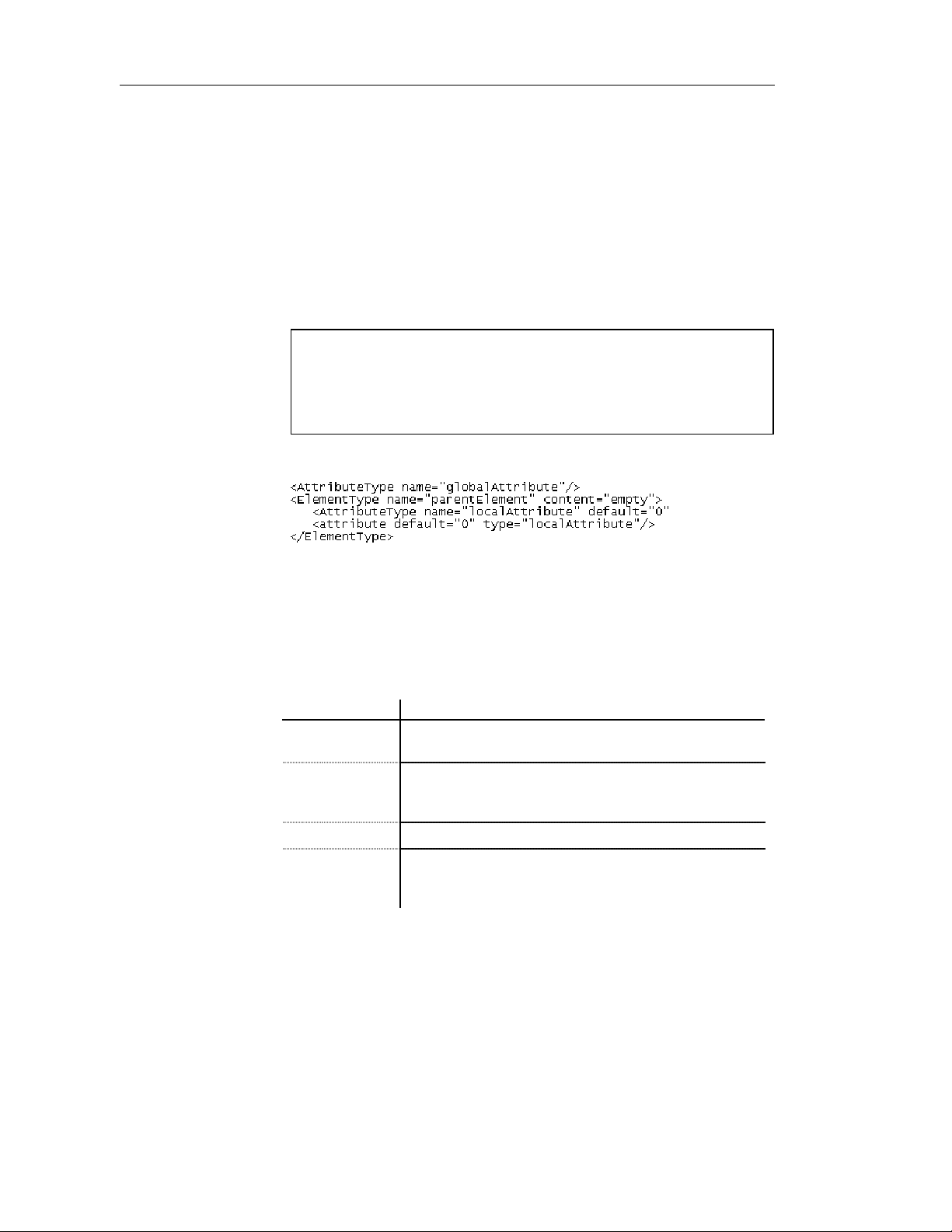
Defining elements
Attribute gener al pr oper t i e s
There are global and local attributes:
♦ Global attributes are defined with the Model menu. In a schema, they are
directly linked to the <schema> tag (root element). They can be reused
for any element in the model through refe rences (See “NUMBER”
attribute in the generated schema)
♦ Local attributes only apply to the elements in which they are created.
They can be defined by reference to a global attribute (See Reference
property)
Global and local attributes in XDR files
In a model targeted with the XML-Data Reduced language, local attrib utes
are first declared separately, like global attributes (with the
<AttributeType> tag and a name attribute), then within their parent
element (with the <attribute> tag and a type attribute).
Extract of an XDR file:
You can derive an attribute data type to extend or restrict its values. (Only
with a model targeted with XSD)
To display an attribute property sheet, double-click its name or its icon in the
Browser tree view.
The General page of an attribute property sheet displays the following
properties:
Property Description
Name The name of the item which should be clear and meaningful,
and should convey the item's purpose to non-technical users
Code The technical name of the item used for generating code or
scripts, which may be abbreviated, and should not generally
include spaces
Comment Descriptive label of the attribute
Stereotype Sub-classification used to extend the semantics o f an object
without changing its structure. It can be predefined or user-
defined
48 PowerDesigner
Page 61
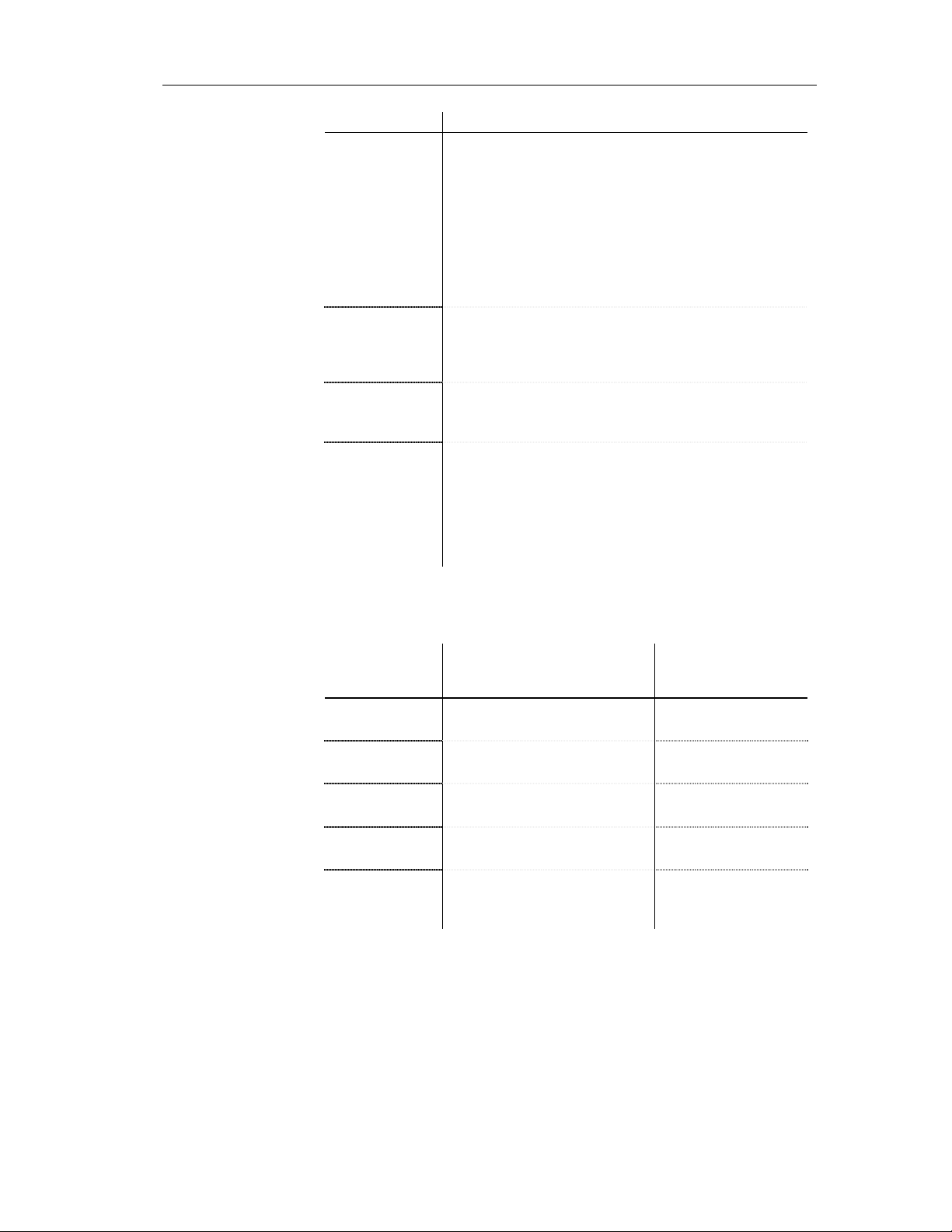
Chapter 2 Building an XML model
Property Description
Reference Name of an attribute in the current model or another model
opened in the worksp ace. A reference allows you to reuse an
attribute with all its properties without having to define it
again. Use the dropdown listbox to select an attribute in the
current model. Use the Browse tool to select an attribute from
any model opened in the workspace. If you select an attribute
from another model, a shortcut is created with the referencing
attribute. When you define a reference, name and code
properties are grayed. The name and cod e are those of the
target attribute
Type Attribute data type. It must be a qualified name (See
Glossary). Use the dropdown listbox to select a built-in data
type. Use the Browse tool to select a simple type defined in
the current model or another model opened in the workspace
Embedded Type If selected, the attribute data type disappears and a <simple
type> tag is created in the schema within the <attribute> tag.
Only available in a model targeted with XSD
Derivation Derivation method for the attribute data type. Used to extend
or restrict the values of the attribute data type. When you
define a derivation, the data type disappears. You must click
Apply and then the Properties tool to select a type, a base
type or member types for the corresponding derivation (list,
restriction or union). Only available in a model targeted with
XSD
Defining attributes
in XDR files
XSM User's Guide 49
In a model targeted with the XML-Data Re duced language, attributes tags are
defined by different attributes:
Property or page in
XDR attribute
for an attribute Description
name
default
dt:type
dt:values
type
To specify the name of a global
attribute
To specify a default value for both
global and local attributes
To specify a data type for a global
attribute
To specify a list of available
values for a global attribute
To specify the name of a global
attribute as reference for a local
attribute
attribute property
sheet
Name
Detail page
Type
Values page
Reference
Page 62
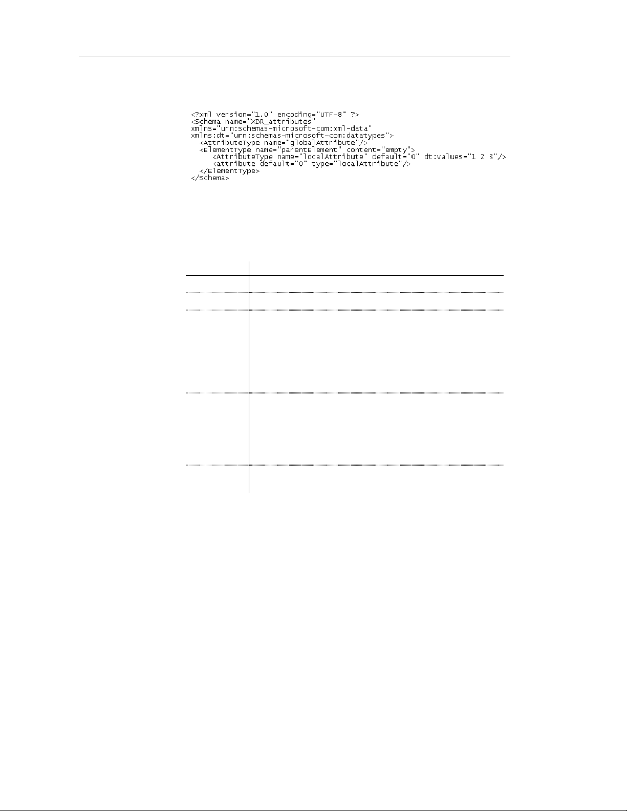
Defining elements
Example of an XDR file:
Attribute det ai l properties
The Detail page of an attribute property sheet displays the following
properties:
Property Description
Default Default value. Enter a default value only if there is no fixed value
Fixed Fixed value. Enter a fixed value only if there is no default value
Attribute values page
Use
Form
ID ID of the attribute. Its value must be of type ID and unique within
Indicator of how the attribute is used. If you select Optional, the
attribute is optional and may have any value. If you select
Prohibited, the attribute cannot be used. Use this value to
prohibit the use of an existing attribute in the restriction of
another complex type. If you select Required, the attribute must
appear at least once and may have any value matching its data
type
Form of the attribute. If you select Qualified, Form must be
qualified by combinin g the target namespace of the schema with
the no-colon-name (See Glossary) of the attribute. If you select
Unqualified, Form is not required to be qualified with the
namespace prefix and is matched again s t the no-colon-name of
the attribute
the model containing the attribute
The Values page of an attribute property sheet is only available in a model
targeted with DTD or XDR. You can set a list of predefined values for an
attribute.
50 PowerDesigner
Page 63
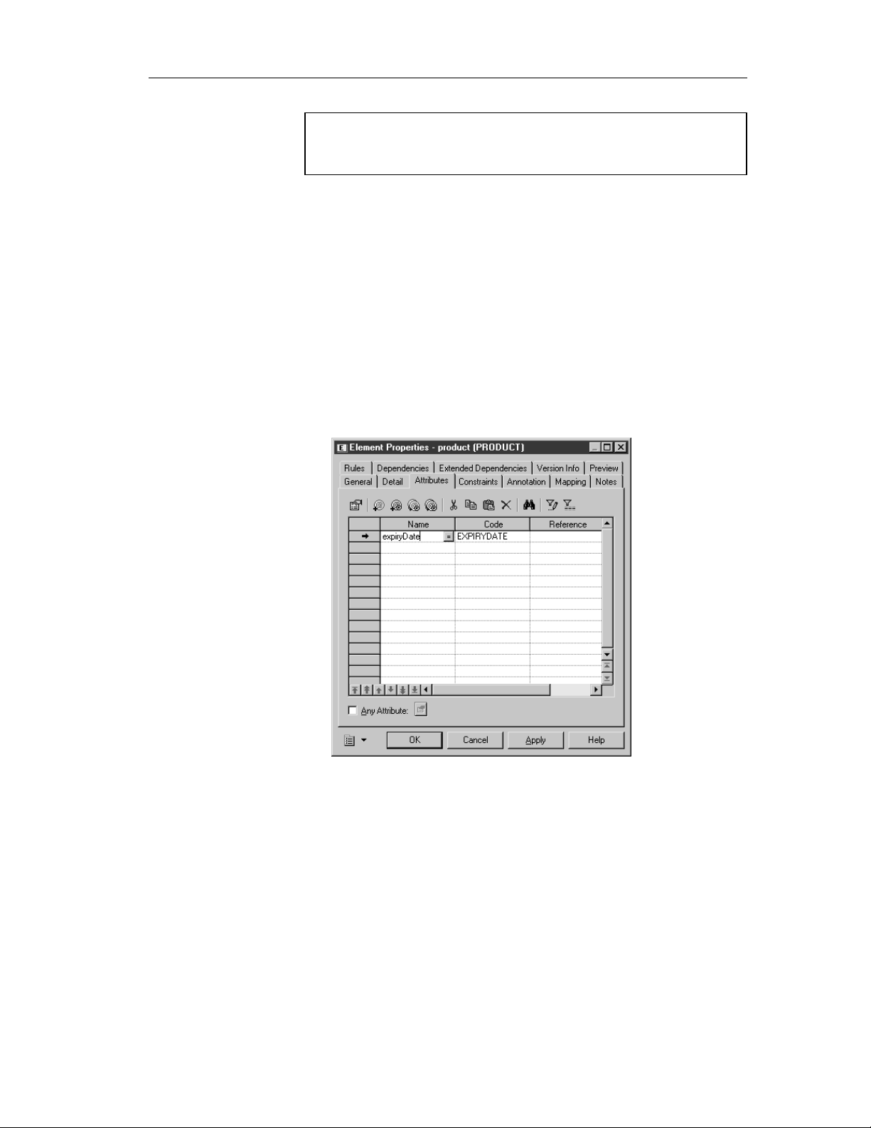
Element values with XDR
In a model targe ted with the XML-Data Reduced language, there is also a
Values page in the element property sheet.
Adding an attribute to an element
To add an attribute to an element:
1 Double-click the element symbol in the diagram.
The element property sheet appears.
2 Click the Attributes tab to display the Attributes page.
3 Click the Add Attribute tool to add an attribute to the list.
or
Click an empty row in the list.
4 Type a name and a code for the attribute.
Chapter 2 Building an XML model
5 Click OK.
XSM User's Guide 51
Page 64

Defining elements
The element symbol appears in the diagram with the attribute name. In
the example, <None> indicates that no data type has been defined for the
attribute.
Modifying element display preferences
You can modify the following display preferences for an element by selecting
Tools→Display Preferences:
Preference Description
Attributes Displays attributes and attribute values of the element
Display limit Maximum number of attributes displayed
Stereotype Displays the stereotype of the element
Type Displays the data type of the element
Show XPath An XPath expression indicates the relationship between an
element and the root el ement (<schema> tag). Select Never,
if you do not want the elements XPath expressions to be
displayed. Select Always, if you want all the elements to
have their XPath expression displayed. Select Root symbol,
if you only want the root symbols (global elements in the
main diagram or parent elements in partial diagrams) to
have their XPath expression displayed
Element Attributes
Select Type, if you want the attributes data types to be
displayed
For more information on XPath expressions, see section Defining an
identity constraint selector.
Linking child elements to a parent element
An element composed of other elements is a parent element with child
elements.
52 PowerDesigner
Page 65

Child elements are linked to their parent element through a group particle.
Defining group particles
Group particles indicate how child elements are related with their parent
element.
You can choose a group particle from the following list:
Tool Tooltip Description
Chapter 2 Building an XML model
Sequence Child elements must appear at least once in the order of
their declaration
Choice Only one child element can be linked to the parent
element
All Child elements can appear in any order and each of
them once or not
In a schema, a group particle is declared with its corresponding tag:
<sequence>, <choice> or <all>.
Group particles in
XDR files
In a model targeted with the XML-Data Reduced language, group particl es
are declared through the order attrib ute of an <ElementType> tag:
Group particle Value of the order attribute in XDR
Sequence seq
Choice one
All many
Extract of an XDR file:
XSM User's Guide 53
Page 66

Defining elements
Group particles properties
To display a group particle property sheet, double-click its symbol in a
diagram.
General properties
Items list
The General page of a group particle property sheet displays the following
properties:
Property Description
Type Type of the group particle. You can change its type by selecting a
value in the dropdown listbox and clicking OK
Minimum Minimum number of times the group particle can occur. To
specify that the group particle is optional, set this property to zero
Maximum Maximum number of times the group particle can occur. For an
unlimited number of times, select unbounded
ID ID of the group particle. Its value must be of type ID and unique
within the model containing the group particle
The Items page of a group particle property sheet allows you to add (or
order) the following objects to a list of child objects:
Tool Tooltip Description
Add Element Adds an element to the list
Add Any Adds an Any to the list. Only available with a
choice or a sequence group particle
Add Group
Particle
Adds a group particle to the list
Add Element
with Reference
to Element
Add Group with
Reference to
Group
Adds a referencing element to the list. Select a
global element for the reference in t he Selection
dialog box. To use this tool, you must have
previously defined a global element in the current
model
Adds a referencing group to the list. Select a group
for the reference in the Selection dialog box. To use
this tool, you must have previously defined a group
in the current model
When you add an object to the list, an object is created and its symbol
appears in the diagram linked to the group particle.
54 PowerDesigner
Page 67

You can access directly to the Items page of a group particle property sheet
through the contextual menu. Right-click a group particle symbol i n the
diagram and select Items in the contextual menu.
Creating a group particle
There are different ways to create a group particle.
Chapter 2 Building an XML model
From an element
property sheet
The same procedure applies for groups and complex types.
To create a group particle from an element property sheet:
1 Select a group particle from the Group type dropdown listbox of the
element property sheet.
2 Click OK.
The element symbol appears selected, with an Expand tab (+) on its
right side.
3 Click an empty space in the diagram, to deselect the element symbol, and
click the Expand tab (+) to reveal the group particle symbol and its link
with the element symbol.
Note the Collapse tab (-) on the right side of the element symbol. If you
click it, the group particle symbol and its link are replaced by an Expand
tab (+).
Click the Expand tab (+) to recover the group particle symbol and its
link.
4 Double-click the group particle symbol to display the group particle
property sheet.
5 Select the Items page to display a list of items.
6 Click the Add Element tool for each child element you create in the list.
or
Click an empty row in the list for each child element you want to create.
XSM User's Guide 55
Page 68

Defining elements
7 Click OK.
The group particle symbol appears selected, with an Expand tab on its
right side.
8 Click an empty space in the diagram, to deselect the group particle
symbol, and click the Expand tab to reveal the child element symbols
and their link.
Name and code uniqueness
To respect the name and code uniqueness within a namespace, child
elements are defined within an internal namespace which is their parent
element. Therefore, there cannot be a conflict between a parent and a child
name.
For more information on the namespace concept, see section Managing
the namespace in models, in chapter Managing Models of the General
Features Guide.
From the palette
56 PowerDesigner
To create a group particle from the palette:
1 Select a group particle tool in the palette.
2 Click the element symbol in the diagram.
The group particle symbol appears in the diagram, linked to the element
symbol.
3 Click the Element tool in the palette.
4 Click the group particle symbol in the diagram for each child element
you need.
Page 69

Chapter 2 Building an XML model
The child elements appear one by one in the diagram, linked to the group
particle symbol.
5 Right-click to recover the Pointer.
Clicking an element symbol with the Element tool
When you click an element symbol with the Element tool, a sequence
symbol (by default) appears in the diagram between the parent element
and the child element.
To add other child elements, click the sequence symbol with the Element
tool.
To change the group particle, double-click the sequence symbol to display
its property sheet, then select another group particle in the Type dropdown
listbox and click OK.
How to link a child object to a group particl e?
XML objects do not support standard link objects. To link a child object to a
group particle, you must click the child object tool in the palette and then
click the group particle symbol in the diagram. This will automatically create
a link between both objects. See the following table for allowed links:
Caution
A group particle cannot be created from scratch in a diagram.
It must be the child element of an element, a group or a complex type.
Tool Sequence symbol Choice symbol All symbol
No link
Any
XSM User's Guide 57
Page 70

Defining elements
Tool Sequence symbol Choice symbol All symbol
A referencing group
is created. You must
now select a group
for the reference
No link No link No link
No link No link No link
All
Pointer indications
A referencing group
is created. You must
now select a group
for the reference
No link
No link
No link
When you cannot click a symbol or an empty space in a diagram, the
Pointer displays a forbidden sign (See complex type in Tool column).
When there is a possibility to create a symbol above, below or next to
another one, the Pointer displays an arrow indicating the corresponding
direction (See element in Tool column).
Defining Any properties
Any allows you to attach any type of object to a choice or a sequence group
particle.
For example:
58 PowerDesigner
Page 71

Chapter 2 Building an XML model
♦ Generated XSD file:
In an XSD file, Any is declared with the <any> tag.
♦ Generated DTD file:
In a DTD file, Any is declared within an <!ELEMENT> tag with the
keyword “ANY”.
♦ Generated XDR file:
In an XDR file, Any is declared through of an <ElementType > tag
(resources in the example) with its model attribute set to “open”.
Although it appears in a diagram, Any is not considered as an object in
an XDR file.
To display an Any property sheet, double-click its symbol in a diagram.
Any general pr oper t i e s
The General page of an Any property sheet displays the following properties:
Property Description
Stereotype Sub-classification used to extend the semantics o f an object
without changing its structure. It can be predefined or userdefined
Minimum Minimum number of times the Any can occur. To specify that
the Any is optional, set this attribute to zero
Maximum Maximum number of times the Any can occur. For an
unlimited number of times, select unbounded
XSM User's Guide 59
Page 72

Defining elements
Property Description
ID ID of the Any. Its value must be of type ID and unique within
the model containing the Any. Only available in a model
targeted with XSD
Namespace Namespaces containing th e objects that can be used. If you
select ##any, objects from any namespace can be used. If you
select ##other, objects from any namespace other than the
target namespace of the schema can be used. If you select
##local, obj ect s that are not qualified with a namespace can
be used. If you select ##targetNamespace, objects from the
target namespace of the schema can be used. If you type a
combination of URI references, ##targetNamespace and
##local, provi ded they are separated by a white space, object s
from this combination can be used. Only available in a model
targeted with XSD
Process contents Indicator of how an XML processor should handle validation
of XML documents containing the objects specified by the
Any. If you select Strict, the XML processor must obtain the
schema and validate any object of the specified namespaces.
If you select Lax, the XML processor will try to obtain the
schema and validate any object of the specified namespaces.
If the schema cannot be found, no error will occur. If you
select Skip, the XML processor will not try to validate the
objects of the specified namespaces. Only available in a
model targeted with XSD
To create an Any:
1 Select the Any tool in the palette.
2 Click a choice or a sequence symbol in the diagram.
The Any symbol appears in the diagram attached to the choice or
sequence symbol.
3 Right-click to recover the Pointer.
or
Click the Pointer tool in the palette.
4 Double-click the Any symbol in the diagram.
The Any property sheet appears.
60 PowerDesigner
Page 73

Chapter 2 Building an XML model
5 Define the Any properties in the different pages of the property sheet.
6 Click OK.
Modifying the Any display preference
You can modify the Stereotype display preference for Any by selecting
Tools→Display Preferences.
Defining Any Attribute properties
The Any Attribute feature allows you to insert any attribute of specified
namespaces into an element, a complex type or an attribute group
declaration. It is only available in a model targeted with XSD.
In a schema, Any Attribute is declared with the <anyAttribute> tag.
XSM User's Guide 61
Page 74
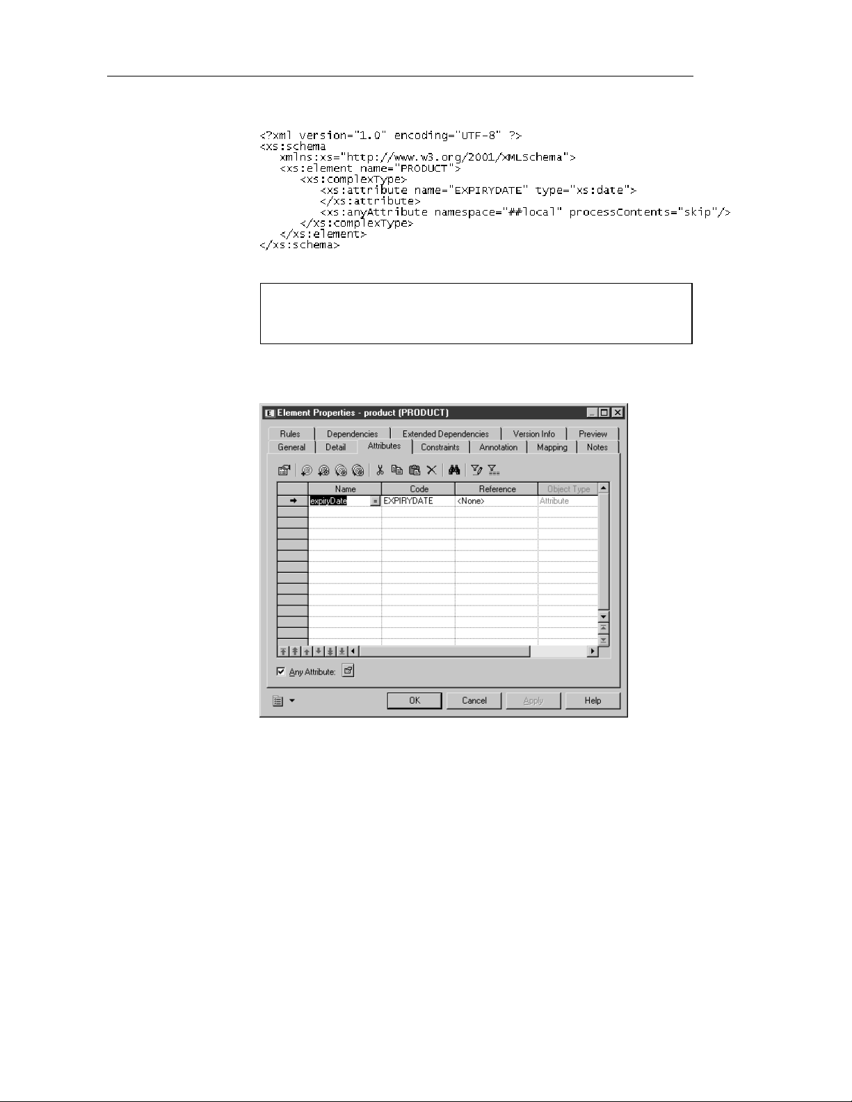
Defining elements
For example:
Caution
Any Attribute only appears in a schema (see the Preview page of a model
property sheet).
The Any Attribute feature is available via a check box in the bottom-left
corner of an Attributes page.
To display an Any Attribute property sheet, select the Any Attribute check
box and then click the Properties tool.
62 PowerDesigner
Page 75

Any Attribute general proper t i e s
The General page of an Any Attribute property sheet displays the following
properties:
Property Description
ID ID of the Any Attribute. Its value must be of type ID and
Namespace Namespaces containing th e attributes that can be u sed. If you
Process contents Indicator of how an XML processor should handle validation
Chapter 2 Building an XML model
unique within the model containing the Any Attribute
select ##any, attributes from any namespace can be used. If
you select ##other, attributes from any namespace other than
the target namespace of the schema can be used. If you select
##local, attributes that are not qual ified with a namespace can
be used. If you select ##targetNamespace, attributes from
the target namespace of the schema can be used. If you type a
white space delimited list with URI references,
##targetNamespace and ##local, attributes from this list can
be used
of XML documents containing the attributes specified by the
Any Attribute. If you select Lax, the XML processor will try
to obtain the schema and validate any attribute of the
specified namespaces. If the schema cannot be found, no error
will occur. If you select Skip, the XML processor will not try
to validate the attri butes of the specified namespaces. If you
select Strict, the XML processor must obtain the schema and
validate any attribute of the specified namespaces
XSM User's Guide 63
Page 76
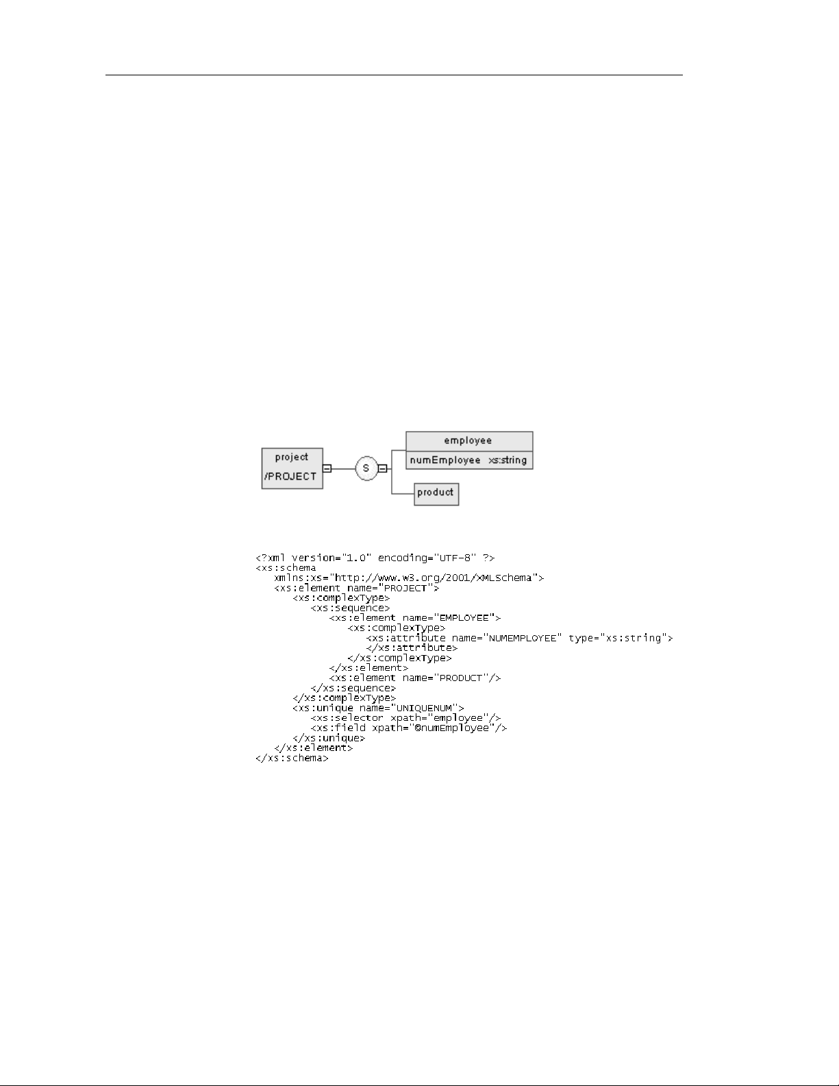
Defining identity constraints
Defining identity constraints
Identity constraints enable you to indicate that element values must be unique
within their specified scope.
There are three kinds of identity constraints: unique, key and keyRef.
Each identity constraint has two specific attributes: selector and field.
In a schema, an identity constraint is declared with its corresponding tag:
<unique>, <key> or <keyRef>.
Identity constraints are only available in a model targeted with XSD.
Defining a unique constraint
A unique constraint specifies that an element or an attribute value (or set of
values) must be unique or null within a specified scope.
For example:
Generated schema:
64 PowerDesigner
Page 77

The UNIQUENUM unique constraint, defined on the project element,
specifies that the numEmployee attribute must be unique or null within the
employee element
To display a unique property sheet, double-click its name or its icon in the
Browser tree view.
Unique general properties
The General page of a unique property sheet displays the following
properties:
Property Description
Name Name of the unique constraint. It must be a no-colon-name
Code Code of the unique constraint. It must be a no-colon-name
Comment Descriptive label of the unique constraint
Stereotype Sub-classification used to extend the semantics o f an object
ID ID of the unique constraint. Its value must be of type ID and
Chapter 2 Building an XML model
(See Glossary)
without changing its structure. It can be predefined or userdefined
unique within the model containing the unique constraint
Selector (XPath) An XML Path Language expression that selects a set of
elements across which the values specified in the Fields page
must be unique. There must be one and only one selector
For more information on Selector or XPath, see section Defining an
identity constraint selector.
Unique fields properties
The Fields page of a unique property sheet displays a list of XPath
expressions.
If there is more than one field (or XPath expression), the combination of
fields must be unique.
For more information on XPath expressions, see section Defining an
identity constraint selector.
XSM User's Guide 65
Page 78
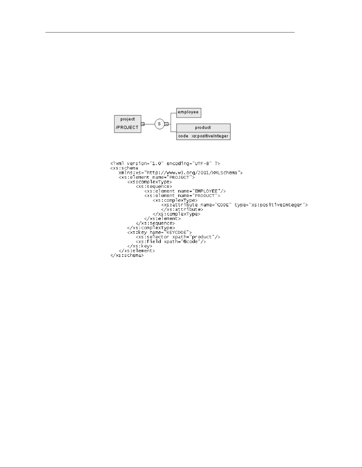
Defining identity constraints
Defining a key constraint
A key constraint specifies that an element or an attribute value (or set of
values) must be a key within a specified scope.
A key means that data should be unique, not null and always present within a
specified scope.
For example:
Generated schema:
The KEYCODE key constraint, defined on the project element, specifies that
the code attribute must be unique, not null and always present within the
product element.
To display a key property sheet, double-click its name or its icon in the
Browser tree view.
66 PowerDesigner
Page 79

Key general properties
Chapter 2 Building an XML model
The General page of a key property sheet displays the following properties:
Property Description
Name Name of the key constraint. It must be a no-colon-name (See
Glossary)
Code Code of the key constraint. It must be a no-colon-name
Comment Descriptive label of the key constraint
Stereotype Sub-classification used to extend the semantics o f an object
without changing its structure. It can be predefined or user-
defined
ID ID of the key constraint. Its value must be of type ID and
unique within the model containing the key constraint
Selector (XPath) An XML Path Language expression that selects a set of
elements across which the values specified in the Fields page
must be unique. There must be one and only one selector
For more information on Selector or XPath, see section Defining an
identity constraint selector.
Key fields properti es
The Fields page of a key property sheet displays a list of XPath expressions.
If there is more than one field (or XPath expression), the combination of
fields must be unique.
For more information on XPath expressions, see section Defining an
identity constraint selector.
Defining a keyRef constraint
A keyRef constraint specifies that an element or attribute value (or set of
values) corresponds to the value of a specified key or unique constraint.
A keyRef is a reference to a key or a unique constraint.
XSM User's Guide 67
Page 80

Defining identity constraints
For example:
Generated schema:
The KEYREF_UNIGOLD keyRef, defined on the product element, by
reference to the UNIGOLD unique constraint, specifies that the gold attribute
must be unique or null within the component_2 element, as well as it must be
unique or null within the component_1 element (See UNIGOLD).
To display a keyRef property sheet, double-click its name or its icon in the
Browser tree view.
68 PowerDesigner
Page 81

KeyRef general properties
The General page of a keyRef property sheet displays the following
properties:
Property Description
Name Name of the keyRef constraint. It must be a no-colon-name
Code Code of the keyRef constraint. It must be a no-colon-name
Comment Descriptive label of the keyRef constraint
Stereotype Sub-classification used to extend the semantics o f an object
ID ID of the keyRef constraint. Its value must be of type ID and
Reference Name of a key or a unique constraint defined in the current
Selector (XPath) An XML Path Language expression that selects a set of
Chapter 2 Building an XML model
(See Glossary)
without changing its structure. It can be predefined or user-
defined
unique within the model containing the keyRef constraint
model (or another model with a specified namespace). The
Reference value must be a qualified name (See Glossary)
elements across which the values specified in the Fields page
must be unique. There must be one and only one selector
For more information on Selector or XPath, see section Defining an
identity constraint selector.
KeyRef fields properti es
The Fields page of a keyRef property sheet displays a list of XPath
expressions.
If there is more than one field (or XPath expression), the combination of
fields must be unique.
For information on XPath expressions, see section Defining an identity
constraint selector.
Creating an identity constraint
You create an identity constraint from an element property sheet.
XSM User's Guide 69
Page 82

Defining identity constraints
To create an identity constraint from an element property sheet:
1 Click the Constraints tab of an element property sheet.
2 Click the Add Unique, Add Key or Add KeyRef Constraint tool in the
Constraints page.
An identity constraint appears in the list with predefined name and code
(a unique constraint in the example).
3 Modify the name and the code of the identity constraint.
4 Click OK.
Defining an identity constraint selector
An identity constraint selector specifies an XPath expression that selects a set
of elements for an identity constraint (unique, key or keyRef).
An XPath expression is limited to a sub s et of the full XPath l anguage defined
in the W3C Recommendation XML Path Language 1.0.
An XPath expression allows you to locate a node (an element with its
ramifications) in the hierarchical tree structure of an XML document.
70 PowerDesigner
Page 83

XPath abbreviated synt ax
You can use the following abbreviated syntax to define an XPath expression:
Syntax Description
/
Chapter 2 Building an XML model
Root node of the XML document. It is the root
element with its ramifications
.
..
*
employee Selects all the employee child elements of the
s:employee Selects all the employee child el ement s of the
@numEmployee Selects the numEmployee attribute of the
@* Selects all the attributes of the context node
../@numEmployee Selects the numEmployee attribute of the
employee[1] Selects the first employee chil d element of the
employee[last()] Selects the last employee child element of the
*/employee Selects all the employee grandchi ldren of the
Selects the context node. It is the current
element (on which an identity constraint is
defined) with its ramifications
Selects the context node parent
Selects all the child elements of the context
node
context node
context node, defined in the namespace with the
“s” prefix
context node
context node parent
context node
context node
context node
//employee Selects all the employee descendants of the root
node
.//employee Selects the employee descendants of the context
node
company//employee Selects the employee descen dants of the
company child elements of the context node
//company/employee Selects all t he employee elements with company
as parent element in the context node
XSM User's Guide 71
Page 84

Defining identity constraints
Syntax Description
/book/chapter[2]/section[3] Selects the third section in the second chapter of
employee[@dept=”doc”] Selects all the employee child elements of the
employee[@dept=”doc”][3] Selects the third employee child element of the
employee[3][@dept=”doc”] Selects the third employee child element of the
chapter[title] Selects the chapter child elements of the context
the book
context node with a dept attribute set to doc
context node with a dept attribute set to doc
context node only if it has a dept attribute set to
doc
node with at least one title child element
chapter[title=”About this
book”]
employee[@numEmployee and
@dept]
text() Selects all the child nodes of the text context
Defining selector general propert i e s
The General page of a selector property sheet displays the following
properties:
Property Description
XPath An XPath expression relative to the parent element being
declared. It identifies the child elements to which the identity
constraint applies
Stereotype Sub-classification used to extend the semantics of an object
without changing its structure. It can be predefined or userdefined
ID ID of the selector. Its value must be of type ID and unique within
the model containing the selector
Selects the chapter chi ld elements of the context
node with at least one title child element with a
text content set to About this book
Selects all the employee child elements of the
context node with the numEmployee and dept
attributes
node
To display a selector property sheet:
1 Type an XPath expression in the Selector groupbox of an identity
constraint (unique, key or keyRef) property sheet.
72 PowerDesigner
Page 85
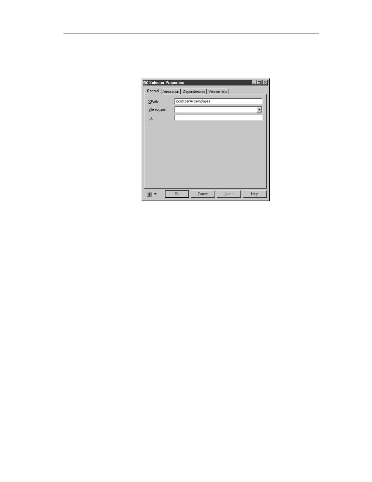
Chapter 2 Building an XML model
2 Click Apply.
3 Click the Properties tool beside the XPath box.
The selector property sheet appears.
4 Define the selector properties in the different pages of the property sheet.
5 Click OK.
Defining an identity constraint field
The Fields page of an identity constraint lets you type one or more XPath
expressions to specify the values used to define an identity constraint
(unique, key or keyRef).
For information on XPath expressions, see section Defining an identity
constraint selector.
XSM User's Guide 73
Page 86

Defining identity constraints
Defining field general proper t i e s
The General page of a field property sheet displays the following properties:
Property Description
XPath An XPath expression relat ive to each element selected by the
Stereotype Sub-classification used to extend the semantics of an object
ID ID of the field. Its value must be of type ID and unique within
To create an identity constraint field:
1 Click the Fields tab of an identity constraint (unique, key or keyRef)
property sheet.
2 Click any empty line in the Fields page.
selector of the identity constraint. It identifies a single element
(with a simple type) whose content or value is used for the
identity constraint
without changing its structure. It can be predefined or userdefined
the model containing the field
An arrow appears at the beginning of the line.
3 Type an XPath expression.
4 Click Apply.
5 Double-click the arrow left of the row.
74 PowerDesigner
Page 87

Chapter 2 Building an XML model
The field property sheet appears.
6 Define the field properties in the different pages of the property sheet.
7 Click OK.
XSM User's Guide 75
Page 88

Defining groups
Defining groups
You can define groups of elements or attributes in an XML model.
Defining a group of elements
A group of elements is a set of elements arranged by a group particle (all,
choice or sequence).
You create a group of elements when you need to reuse a set of elements in
several parts of your model. Once you have defined a group, you can reuse it
elsewhere in the model through referenci ng groups (see Reference property
in Group property sheet).
For example:
The descriptionLines group is reused in the definition of the product element
by clicking the sequence group particle (S) with the palette Group tool. The
Reference property of the referencing group property sheet is then set to
descriptionLines.
76 PowerDesigner
Page 89

Chapter 2 Building an XML model
♦ In the generated XSD file, the group is first declared with the <group>
tag and then reuse d through a reference (ref) set to descriptionLi nes:
♦ In the generated DTD file, the group is expanded directly within its
parent element:
♦ In the generated XDR file, the gr oup is declared through a <gro up> tag,
within an <ElementType> tag with its order attribute set to seq:
Defining group properties
There are global and referencing groups:
♦ Global groups are directly created in a diagram without a parent symbol.
In a schema, they are directly linked to the <schema> tag (root element).
They can be reused within any element or complex type of the model
through references (See desc riptionLines in De fining a group of
elements)
XSM User's Guide 77
Page 90
Defining groups
♦ Referencing groups are created in a diagram within an element, a
complex type or a global group. You must select a global group for their
Reference property (See the following table)
Groups in DTD and XDR files
In a model targeted with DTD or XDR language, there are no global or
referencing gr oups, although they appear on the d iagram.
Groups are expanded within their parent element and their child elements
are declared individually as global elements. (See generated DTD and
XDR files in Defining a group of elements)
To display a group property sheet, double-click its symbol in a diagram.
The General page of a group property sheet displays the following properties:
Property Description
Name Name of the group. It must be a no-colon-name (See Glossary).
Required when the group is global
Code Code of the group. It must be a no-colon-name. Required when
the group is global
Comment Descriptive label for the group
Stereotype Sub-classification used to extend the semantics of an object
without changing its structure. It can be predefined or user-
defined
Reference Name of a group in the current model or another model opened in
the workspace. It must be a qualified name (See Glossary). A
reference allows you to reuse a group with all its properties
without having to define it again. Use the dropdown listbox to
select a group in the current model. Use the Browse tool to select
a group from any model opened in the workspace. If you select a
group from another model, a shortcut is created with the
referencing group. When a reference is defined, the name and
code properties are grayed. The name and code are those of the
target group
Group type Indicator that specifies how child elements are to be used within
the group. Select a group particle (all, choice or sequence)
Minimum Minimum number of times the group can occur. To specify that
the group is optional, set this attribute to zero
Maximum Maximum number of times the group can occur. For an unlimited
number of times, select unbounded
ID ID of the group. Its value must be of type ID and unique within
the model containing this group
78 PowerDesigner
Page 91

Once you have defi ned the reference of a referenc ing group, you can lo cate
the referenc ed group in the diagram by right-clicking t he referencing group
symbol and selecting Find Referenced Group in the contextual menu. The
referenced group appears with handles in the diagram.
You can access directly to the Preview page of a group property sheet. Rightclick a group (or a referencing group) symbol in the diagram and select
Preview in the contextual menu.
Creating a group of elements
You can create a group of elements:
♦ From the palette
♦ From the Browser tree view
♦ From the List of Groups in the Model menu
For more information on the different ways to create a group, see
section Creating an object in chapter Managing objects of the General
Features Guide.
Chapter 2 Building an XML model
To create a group of elements from the palette:
1 Click on the Group tool in the palette.
2 Click an empty space in the diagram.
A group symbol appears in the diagram at the click position.
3 Click the Pointer tool in the palette.
or
Right-click to recover the Pointer.
4 Double-click the group symbol in the diagram.
The group property sheet appears.
XSM User's Guide 79
Page 92
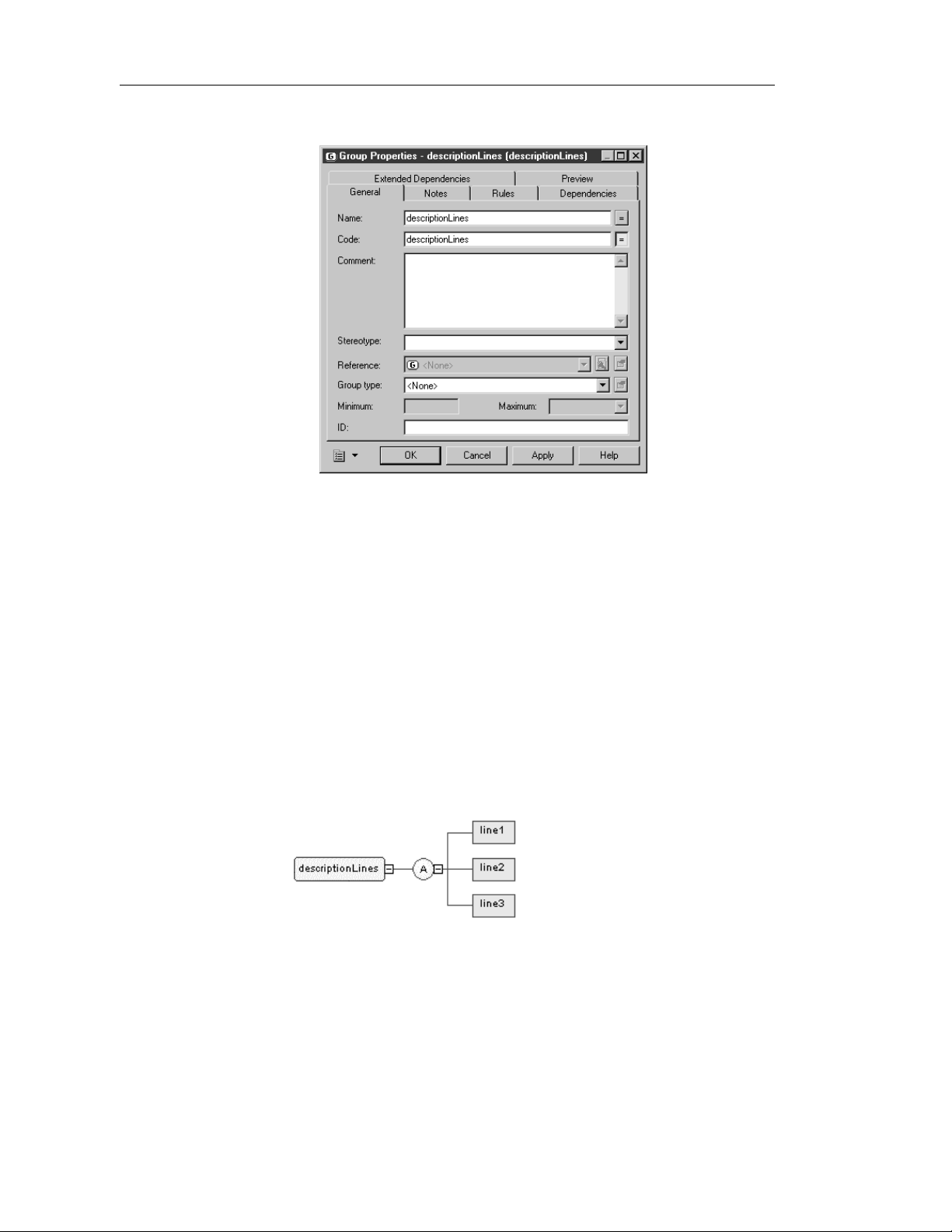
Defining groups
5 Type a name and a code for the group.
6 Click OK.
7 Select a group particle tool in the palette (Sequence, Choice or All).
8 Click the group symbol in the diagram.
The group particle symbol appears attached to the group symbol.
9 Select the Element tool in the palette.
10 Click the group particle symbol in the diagram for each child element
you want to create.
The child element symbols appear attached to the group particle symbol.
11 Double-click a child element symbol to display its property sheet.
12 Type a name and a code for the child element.
13 Repeat steps 11 and 12 for each child element.
14 Click OK.
80 PowerDesigner
Page 93
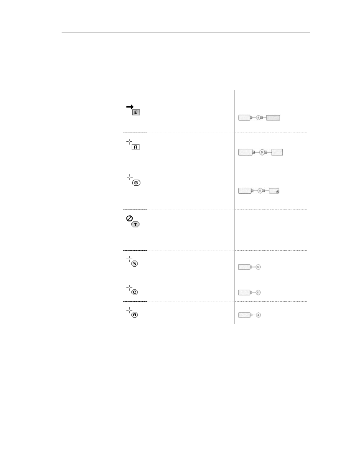
Chapter 2 Building an XML model
How to link a child object to a group of elements?
XML objects do not support standard link objects. To link a child object to a
group, you must click the child object tool in the palette and then click the
group symbol in the diagram. This will automatically create a link between
both objects. See the following table for allowed links:
Tool Action Result
If you click a group symbol with the
Element tool, a sequence group
particle and a child element symbol
are created. You can modify the
group particle via its property sheet
If you click a group symbol with the
Any tool, a sequence group particle
and an any symbol are created. You
can modify the group particle via its
property sheet
If you click a group symbol with the
Group tool, a sequence group particle
and a referencing group are created.
You can modify the group particle via
its property sheet. You must now
select a group for the reference
If you click a group symbol with the
Complex Type tool, a complex type
symbol appears superposed, but not
linked, to the group symbol. A global
complex type cannot be the child of a
group
If you click a group symbol with the
Sequence tool, a sequence group
particle appears linked to the group
symbol
If you click a group symbol with the
Choice tool, a choice group particle
appears linked to the group symbol
If you click a group symbol with the
All tool, an all group particle appears
linked to the group symbol
XSM User's Guide 81
No link
Page 94
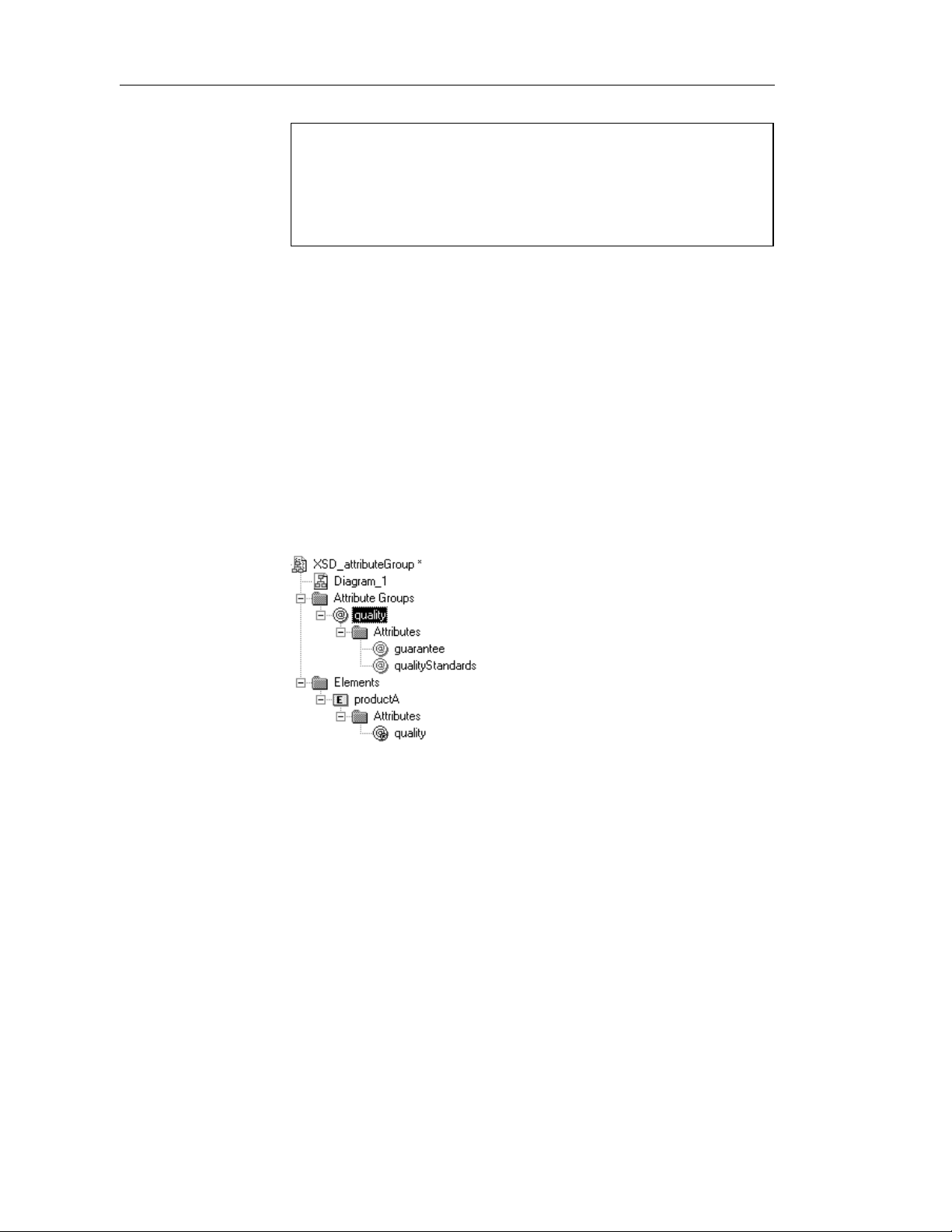
Defining groups
Pointer indications
When you cannot click a symbol or an empty space in a diagram, the
Pointer displays a forbidden sign (See complex type in Tool column).
When there is a possibility to create a symbol above, below or next to
another one, the Pointer displays an arrow indicating the corresponding
direction (See element in Tool column).
Modifying the group display preference
You can modify the Stereotype display preference for a group by selecting
Tools→Display Preferences.
Defining a group of attributes
An attribute group is a set of attributes. You define an attribute group
globally (with the Model menu) and then you reuse it locally (with only its
reference) in the definition of an element, a complex type or another attribute
group.
For example:
The quality attribute group is composed of the guarantee and
qualityStandards attributes. The productA element reuses the quality attribute
group via the Attributes page of its property sheet (See attribute group tools).
82 PowerDesigner
Page 95
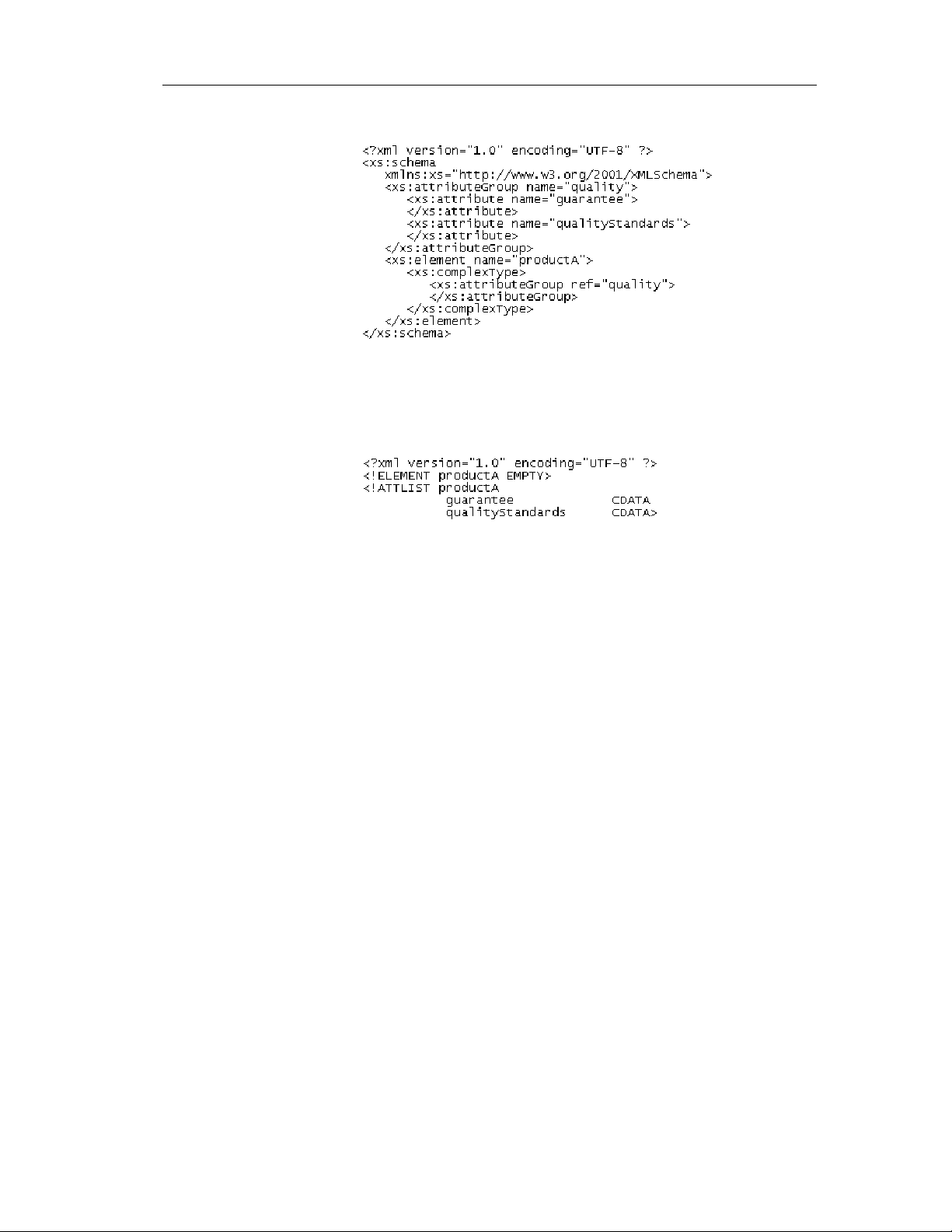
Chapter 2 Building an XML model
♦ Generated XSD file:
In a schema, a group of attributes is declared with the <attributeGroup>
tag. It can contain the following tags: <attribute>, <attributeGroup> or
<anyAttribute>.
♦ Generated DTD file:
Attribute groups are not supported by XDR.
Defining attribute group proper t i e s
To display an attribute group property sheet, double-click its name or its icon
in the Browser tree view.
Attribute group
general properties
There are global and referencing attribute groups:
♦ Global attribute groups are defined with the Model menu. In a schema,
they are directly linked to the <schema> tag (root element). They can be
reused for any element, complex type or attribute group in the model
through references (See quality attribute group in the generated schema)
♦ Referencing attribute groups are used within an element, a complex type
or an attribute group definition. For this, you must use the attribute group
tools in the Attributes page of an element, a complex type or an attribute
group property sheet
XSM User's Guide 83
Page 96

Defining groups
The General page of an attribute group property sheet displays the following
properties:
Property Description
Name Name of the attribute group. It must be a no-colon-name (See
Glossary). Required when the attribute group is global
Code Code of the attribute group. It must be a no-colon-name.
Required when the attribute group is global
Comment Descriptive label of the attribute group
Stereotype Sub-classification used to extend the semantics of an object
without changing its structure. It can be predefined or user-
defined
Reference Name of an attribute group from the current model or any
model opened in the workspace. It must be a qualified name
(See Glossary). If you select an attribute group from another
model, a shortcut is created with the referencing attribute
group. A reference allows you to reuse an attribute group with
all its properties without having to define it again. When a
reference is defined, the name and code properties are grayed.
The name and code are those of the target attribute group
ID ID of the attribute group. Its value must be of type ID and
unique within the model containing this attribute group
Attribute group
attributes
The Attributes page of an attribute group property sheet allows you to add
attributes to an attribute group declaration:
properties
Tool Tooltip Description
Add Attribute Creates a local attr i bute
Add Attribute Group with
Reference to Attribute
Group
Add Attribute with
Reference to Attribute
from a Selection
Adds an attribute group with a reference
to an attribute group defined in the current
model. Select a name in the Reference
dropdown listbox. You can also type a
new name in the Reference column and
then define a new attribute group in the
Attribute Groups list (See Model menu)
Adds one or several attributes with a
reference to global attributes defined in
the current model. Select one or several
global attributes in the Selection dialog
box
84 PowerDesigner
Page 97

Tool Tooltip Description
Creating an attribute group
You can create an attribute group:
♦ From the Browser tree view
♦ From the List of Attribute Groups in the Model menu
For more information on the different ways to create an attribute group,
see section Creating an object in chapter Managing objects of the General
Features Guide.
To create an attribute group from the Browser tree view:
Chapter 2 Building an XML model
Add Attribute Group with
Reference to Attribute
Group from a Selection
Any Attribute Adds any attribute of a specified
Adds one or several attribute groups with
a reference to attribute groups defined in
the current model. Select one or several
attribute groups in the Selection dialog
box
namespace
1 Right-click the name or the icon of the XML model.
2 Select New→Attribute Group in the contextual menu.
The attribute group property sheet appears.
XSM User's Guide 85
Page 98

Defining groups
3 Type a name and a code for the attribute group.
4 Click OK.
5 Select the Attributes page.
6 Select different tools to add items to the attribute group.
7 Click Apply.
8 Double-click on the left of a row to display an item property sheet.
9 Type a name and a code for the item.
10 Repeat steps 8 and 9 for each item.
11 Click OK.
86 PowerDesigner
Page 99

Chapter 2 Building an XML model
Managing external shortcuts through references
and data types
External shortcuts allow you to share objects between different models. You
can define external shortcuts in an XML model, but you cannot use them
directly in the model, except as substitution groups for elements (see Detail
page in element property sheet).
You can define external shortcuts for any global object (with no parent object
in the diagram), except for imports, includes, redefines and annotations.
Internal shortcuts allow you to share objects between packages of a same
model. You cannot define internal shortcuts since an XML model does not
support packages.
External shortcuts are automatically generated in the following situations:
References
Data types
When you use the Reference property to define an element, an attribute, a
group or an attribute group, by reference to a similar object in another model
opened in the workspace, a shortcut is created between the referencing object
and the target object.
The shortcut appears in the current model with a specific item in the Browser
tree view and the “(Shortcut)” expression in the reference symbol and item.
The target object keeps track of the referencing object in the Reference tab of
the Dependencies page of its property sheet.
When you define the data type of an element by selecting a simple or a
complex type from another model (using the Browse tool beside the Type
dropdown listbox), a shortcut is created between the current element type and
the target data type.
The shortcut appears in the current model with a specific item in the Browser
tree view.
XSM User's Guide 87
Page 100

Managing external shortcuts through references and data types
Example of shortcuts through a refere nce and a data type :
88 PowerDesigner
 Loading...