

Page 1

OBJECT ORIENTED MODEL
User’s Guide
POWERDESIGNER 7.5
Page 2

Copyright (c) 1988–2000 Sybase, Inc. All rights reserved.
Information in this manual may change without notice and does not represent a commitment on the part of Sybase, Inc. and its
subsidiaries.
The software described in this manual is provided by Sybase, Inc. under a Sybase License agreement. The software may be used
only in accordance with the terms of the agreement.
No part of this publication may be reproduced, transmitted, or translated in any form or by any means, electronic, mechanical,
manual, optical, or otherwise, without the prior written permission of Sybase, Inc. and its subsidiaries.
Sybase, SYBASE (logo), ADA Workbench, Adaptable Windowing Environment, Adaptive Component Architecture, Adaptive
Server, Adaptive Server Anywhere, Adaptive Server Enterprise, Adaptive Server Enterprise Monitor, Adaptive Server
Enterprise Replication, Adaptive Server Everywhere, Adaptive Server IQ, Adaptive Warehouse, AnswerBase, Anywhere
Studio, Ap plication Manager, AppModeler , APT Workbench, APT-Build, APT-Edit, APT-Execut e, APT-FORMS, APTTranslator, APT-Library, ASEP, Backup Server, BayCam, Bit-Wise, Certified PowerBuilder Developer, Certified SYBASE
Professional, Certified SYBASE Professional Logo, ClearConnect, Client-Library, Client Services, CodeBank, Column Design,
ComponentPack, Connection Manager, CSP, Data Pipeline, Data Workbench, DataArchitect, Database Analyzer, DataExpress,
DataServer, DataWindow , DB-Library, dbQueue , Developers Work bench, Direct Connect Anywhere, DirectC onnect,
Distribution Director, E-Anywhere, E-Whatever, Electronic Case Management, Embedded SQL, EMS, Enterprise Application
Server, Enterprise Application Studio, Enterprise Client/Server, Enterprise Connect, Enterprise Data Studio, Enterprise
Manager, Enterprise SQL Server Manager, Enterprise Work Architecture, Enterp rise W ork D e s igner, Enterprise W ork
Modeler, EWA, First Impression, Formula One, Gateway Manager, GeoPoint, ImpactNow, InfoMak e r, Information Anywhere,
Information E verywhere, InformationConnect, InstaHe lp, Intellidex, Intern etBuilder, iScript, Jaguar CTS, jConne ct for JDB C,
KnowledgeBase, Logical Memory Manager, MainframeConnect, Maintenance Express, MAP, MDI Access Server, MDI
Database Gateway, media.splash, MetaWorks, MethodSet, MySupport, Net-Gateway, Net-Library, NetImpact, Next
Genera tion Learning, N ext Generation Learning St udio, O DEV ICE, OASiS, OASiS logo, ObjectConnect, ObjectCycle,
OmniConnect, OmniSQL Access Module, OmniSQL Toolkit, Open Client, Open ClientConnect, Open Client/Server, Open
Client/Server Interfaces, Open Gateway, Open Server, Open ServerConnect, Open Solutions, Optima++, Partnerships that
Work, PB-Gen, PC APT Execute, PC DB- Net, PC Ne t Library, Po wer++, P ower Through Kno wledge, power.stop,
PowerAMC, Pow erBuilder, PowerBuilder Foundatio n Class Library, PowerDesigne r , PowerDimensions, PowerDynamo,
PowerJ, PowerScript, PowerSite, PowerSocket, Powe rs oft, Powe rStage, Powe rStudio, PowerTips, Pow e rs oft Portfolio,
Powersoft Professional, PowerWare Desktop, PowerWare Enterprise, ProcessAnalyst, RelationalBeans, Report Workbench,
Report-Execute, Replication Agent, Replication Driver, Replication Server, Replication Server Manager, Replication Toolkit,
Resource Manager, RW-D isplayLib, RW-Library, S Designor, S-Designor, SAFE, SAFE/PRO, SDF, Secure SQL Server,
Secure SQL Toolset, Security Guardian, SKILS, smart.partners, smart.parts, smart.script, SQL Advantage, SQL Anywhere,
SQL Anywhere Studio, SQL Code Checker, SQL Debug, SQL Edit, SQL Edit/TPU, SQL Everywhere, SQL Modeler, SQL
Remote, SQL Server, SQL Server Manager, SQL SMART, SQL Toolset, SQL Server/CFT, SQL Server/DBM, SQL Server
SNMP SubAgent, SQL Station, SQLJ, STEP, SupportNow, Sybase Central, Sybase Client/Server Interfaces, Sybase
Development Framework, Sybase Financial Server, Sybase Gateways, Sybase Learning Connection, Sybase MPP, Sybase SQL
Desktop, Sybase SQL Lifecycle, Sybase SQL Workgroup, Sybase Synergy Program, Sybase Virtual Server Architecture,
Sybase User Workbench, SybaseWare, Syber Financial, SyberAssist, SyBooks, System 10, System 11, System XI (logo),
SystemTools, Tabular Data Stream, The Enterprise Client/Server Company, The Extensible Software Platform, The Future Is
Wide Open, The Learning Connection, The Model For Client/Server Solutions, The Online Information Center, Transact-SQL,
Translation Toolkit, Turning Imaginatio n Into Reality, UltraLit e, UNIBO M, Unilib, Uninull, Unise p, Unistring, URK Runtime
Kit for UniCode, Viewer, Visual Components, VisualSpeller, VisualWriter, VQL, WarehouseArchitect, Warehouse Control
Center, Warehouse Studio, Warehouse WORKS, Watcom, Watcom SQL, Watcom SQL Server, Web Deployment Kit,
Web.PB, Web.SQL, WebSights, WebViewer, WorkGroup SQL Server, XA-Library, XA- Server and XP Server are trademarks
of Sybase, Inc. or its subsidiaries
Unicode and the Unicode Logo are registered trademarks of Unicode, Inc.
Other trademarks are the property of their respective owners.
Page 3

Contents
About This Book ............................................................................................ix
1 Object-Oriented Model Basics ..........................................1
Functional overview ..................................................................2
UML and object-oriented modeling...........................................3
What is an OOM?.....................................................................4
Objects in an OOM ...................................................................5
Creating a new OOM................................................................ 6
Opening an existing OOM......................................................... 8
Defining OOM model options....................................................9
Defining OOM properties ........................................................ 11
2 Building an Object-Oriented Model.................................13
Defining packages .................................................................. 14
Package properties .......................................................... 14
Displaying text in package symbols.................................. 15
Defining classes......................................................................17
Class properties ............................................................... 18
Analyzing class properties................................................19
Creating a class................................................................21
Inner classes .................................................................... 23
Classifiers......................................................................... 27
Modifying class properties................................................ 27
Adding objects to a class..................................................29
Preview the code of a class or an interface......................33
Displaying text in class symbols....................................... 34
Defining interfaces .................................................................. 36
Interface properties .......................................................... 36
Analyzing interface properties.......................................... 37
Creating an interface........................................................37
Modifying interface properties ..........................................39
Adding inner classes to an interface ................................41
Adding objects to an interface..........................................41
iii
Page 4

Preview the code of an interface......................................45
Displaying text in interface symbols ................................. 46
Defining attributes................................................................... 48
Attribute properties...........................................................49
Analyzing attribute properties........................................... 50
Creating an attribute......................................................... 51
Modifying attribute properties...........................................54
Attaching an attribute to a domain.................................... 57
Copying an attribute to another class............................... 59
Displaying text in attribute symbols.................................. 60
Defining identifiers .................................................................. 62
Identifier properties........................................................... 62
Creating an identifier ........................................................ 63
Adding attributes to an identifier....................................... 64
Modifying identifier properties........................................... 65
Defining operations................................................................. 67
Operation properties......................................................... 67
Analyzing operation properties......................................... 68
Creating an operation....................................................... 68
Modifying operation properties.........................................71
Adding constructors and destructors to a class ............... 73
Adding operations to a class ............................................ 77
Adding Getter and Setter operations to a class................ 79
Creating an implementation operation ............................. 81
Modifying the code of an implementation operation......... 83
Copying an operation to another class............................. 84
Displaying text in operation symbols................................ 85
Defining parameters ............................................................... 88
Parameter properties........................................................ 88
Creating a parameter ....................................................... 89
Defining generalizations.......................................................... 91
Generalization properties ................................................. 91
Analyzing generalization properties.................................. 92
Creating a generalization..................................................92
Modifying generalization properties..................................94
Displaying text in generalization symbols.........................95
Defining associations.............................................................. 97
Association properties......................................................98
Creating an association.................................................... 99
Analyzing cardinality properties......................................100
Changing an association into an associative class ........102
Modifying association properties.................................... 103
Displaying text in association symbols........................... 106
Defining dependencies ......................................................... 108
Dependency properties .................................................. 108
Analyzing dependency properties...................................109
iv
Page 5

Creating a dependency .................................................. 109
Modifying dependency properties...................................111
Displaying text in dependency symbols.......................... 112
Defining realizations.............................................................. 114
Realization properties.....................................................114
Creating a realization......................................................115
Modifying realization properties......................................116
Displaying text in realization symbols.............................118
Defining domains .................................................................. 120
Domain properties..........................................................120
Creating a domain..........................................................121
Indicating data type, length, and precision..................... 122
Selecting a data type for a domain................................. 123
Selecting a data type from a list of standard data types.125
Modifying domain properties ..........................................129
Defining check parameters................................................... 130
Setting standard check parameters for objects..............130
Defining additional check parameters for objects .......... 131
Using a validation rule in check parameters...................132
3 Managing Object-Oriented Models...............................135
Checking an OOM ................................................................136
Object parameters verified by Check model .................. 136
OOM check options........................................................ 137
Indicating error severity..................................................137
Object selection in the Check Model..............................138
Checking a OOM............................................................ 138
Making corrections based on OOM check results.......... 141
Merging two OOM.................................................................144
Opening a Rose model in an OOM.......................................145
Objects imported ............................................................ 146
Objects not imported ...................................................... 147
4 Reverse Engineering......................................................149
What is reverse engineering?...............................................150
Reverse engineering Java .................................................... 151
Reverse engineering Java options................................. 152
Loading a JDK library model in the workspace .............. 153
Reverse engineering Java source files
without code body...........................................................154
Reverse engineering Java source files ..........................156
Reverse engineering compiled Java files.......................158
Reverse engineering Java files from a source directory 161
Reverse engineering archived .jar or .zip files................ 163
Reverse engineering PowerBuilder.......................................166
v
Page 6

Reverse engineering PowerBuilder options ................... 166
Loading a PowerBuilder library model in
the workspace................................................................ 168
Reverse engineering objects from a
PowerBuilder application................................................ 169
Reverse engineering objects from SRU files ................. 171
Reverse engineering XML .................................................... 174
Reverse engineering XML options ................................. 174
Reverse engineering XML files ...................................... 175
Reverse engineering into a new OOM.................................. 177
5 Generating Objects from an OOM ................................179
Generating objects................................................................180
Selecting objects to include in the generation................ 180
Generating Java source files ................................................ 182
Defining Java generation options...................................182
Generating Java class definition files............................. 184
Creating Java BeanInfo classes..................................... 186
Generating objects for PowerBuilder.................................... 189
Defining PowerBuilder generation options .....................189
Generating objects for a PowerBuilder application ........ 191
Generating PowerBuilder objects in sru files..................193
Generating for XML .............................................................. 195
Defining XML generation options ................................... 195
Generating XML objects................................................. 196
Customizing scripts...............................................................199
6 Generating a Conceptual Data Model f rom an
Object-Oriented Model...................................................201
Generating OOM objects to a CDM...................................... 202
Translating OOM objects into CDM objects................... 202
Translating OOM data types for a CDM ............................... 203
Translating Java data types for a CDM..........................203
Generating a CDM from an OOM......................................... 204
Generating and updating a CDM.................................... 204
CDM generation options................................................. 205
Object selection parameters .......................................... 206
Generating a new CDM.................................................. 207
Updating an existing CDM.............................................. 210
7 Generating a Physical Data Model from an
Object-Oriented Model...................................................215
Generating OOM objects to a PDM...................................... 216
Translating OOM objects into PDM objects................... 216
vi
Page 7

Translating OOM data types for a PDM................................217
Translating Java data types for a PDM ..........................217
Generating a PDM from an OOM ......................................... 218
Generating and updating a PDM.................................... 218
Defining PDM generation options...................................220
Object selection parameters...........................................220
Generating a new PDM..................................................221
Updating an existing PDM.............................................. 224
8 Using Object Languages ...............................................229
Object languages..................................................................230
Types of object language ...............................................230
Accessing object language properties............................231
Modifying the current object language............................231
Modifying linked object language properties .................. 233
Changing the object language of an OOM.....................235
Creating a new object language..................................... 235
Using the object language editor .......................................... 239
Modifying values in the object language editor............... 240
Object language editor categories ........................................ 241
General category............................................................ 241
UML category.................................................................241
Script category................................................................245
Extended Attributes category .........................................249
9 Using Business Rules....................................................251
What is a business rule?....................................................... 252
Defining business rules in an OOM ...................................... 253
Types of business rule ................................................... 253
Business rule properties................................................. 254
Creating a business rule.................................................254
Applying business rules to objects........................................ 256
Applying a business rule to an object............................. 256
Attaching an expression to a business rule.................... 257
Glossary .........................................................................................259
Index .........................................................................................263
vii
Page 8

viii
Page 9

About This Book
Subject
Audience
Where to find
information
This book describes the PowerDesigner Object-Oriented Model environment.
It shows you how to do the following:
♦ Build an Object-Oriented Model (OOM)
♦ Use classes, packages, and other modeling objects
♦ Verify the model and import a Rose model
♦ Generate a Conceptual Data Model and a Physical Data Model from the
OOM
♦ Reverse engineer Java files
♦ Generate Java source files
Anyone who will be designing or building an OOM with PowerDesigner
Object-Oriented Model will find this book useful. It requires an
understanding of object modeling, as well as familiarity with UML theory.
Some experience with database structure and terminology, is helpful but not
required.
This book focuses on the design and construction of an object-oriented
model. General information about the PowerDesigner modeling environment,
for example using many of the graphic tools, interface features, merging
models, and using the Browser, can be found in the PowerDes igner General
Features Guide.
ix
Page 10

About This Book
To help you do your work more easily, this book is divided into chapters that
focus on particular goals.
If you want to Use these parts of the book
Learn about the environment Object-Oriented Model Basics
Build an object-o ri ented model Building a Object-Orien ted Model
Verifying the model and
importing a Rose model
Generating a conceptual data
model or a physical data model
Managing Object-Oriented Models
The chapters on generating conceptual and
physical models
x
Page 11

CHAPTER 1
Object-Oriented Model Basics
About this chapter
Contents
This chapter presents the PowerDesigner Object-Oriented Model. It provides
you with an introduction to the basic notions of object-oriented modeling and
the Unified Modeling Language (UML).
Topic Page
Functional overview 2
UML and object-oriented modeling 3
What is an OOM? 4
Objects in an OOM 5
Creating a new OOM 6
Opening an existing OOM 8
Defining OOM model options 9
Defining OOM properties 11
1
Page 12

Functional overview
Functional overview
PowerDesigner Object-Oriented Model is a powerful design tool for objectoriented modeling. It gives you all the advantages of a graphical object
design implementation.
With this product, you can:
♦ Build an Object-Oriented Model (OOM)
♦ Generate Ja va class source files (.java)
♦ Generate PowerBuilder objects
♦ Reverse engineer Java files (.class, .java, or .jar)
♦ Reverse engineer PowerBuilder objects
♦ Import a Conceptual Data Model (CDM)
♦ Import a Physical Data Model (PDM)
♦ Generate a Conceptual Data Model (CDM)
♦ Generate a Physical Data Model (PDM)
♦ Customize the Object-Oriented Model to suit physical and performance
considerations
♦ Customize and print model reports
2
Page 13

Chapter 1 Object-Oriented Model Basics
UML and object-oriented modeling
What is UML?
Notational
Terminology
What is objectoriented modeling?
UML (The Unified Modeling Language) is a modeling language aimed at
defining standards for object-oriented modeling. UML has become a
standardized language largely through the work of the OMG (Object
Management Group), a group composed of individuals and representatives of
companies involved in object-oriented projects. However, its original
conception drew much of its inspiration from the work of G. Booch, J.
Rumbaugh, and I. Jacobson.
UML has a vocabulary and rules that focus on the conceptual and physical
representation of a system. You use UML symbols and notations to create
your models and diagrams in an OOM.
UML has a well-defined syntax and semantics that is clear and easy to use in
object modeling. All of the terminology used in the OOM interface is
consistent with UML language notations.
Object-oriented modeling refers to the process of using objects as the basic
building blocks for creating a software system. An object in this context
usually means a class, that is, a description of a set of common objects. Each
object or class has identity and behavior. You use these objects to build
models in which the properties of each object interact to perform certain
actions that together make up a system of information.
3
Page 14

What is an OOM?
What is an OOM?
An OOM contains a set of packages, classes, interfaces, and their
relationships. These objects together form a class structure that is the logical
design view of all (or part of) a software system. An OOM is essentially a
static conceptual model of a software system.
You use PowerDesigner Object-Oriented Model to build object-oriented
models (OOM). You can build an OOM for purely object-oriented modeling
purposes, to generate Java files or for PowerBuilder, or you can use objects
from an OOM in a Physical Data Model (PDM), for relational database
design analysis.
When modeling objects graphically, you use diagrams such as the class
diagram.
OOM roles
OOM creation
You can use an OOM to:
♦ Represent the physical organization of objects in a graphic format
♦ Generate Ja va class source files
♦ Generate PowerBuilder objects
♦ Reverse engineer Java class source files
♦ Reverse engineer PowerBuilder objects
♦ Generate a Conceptual Data Model (CDM)
♦ Generate a Physical Data Model (PDM)
There are several ways to create an OOM:
♦ Create an OOM from scratch
♦ Import one or more existing OOM
♦ Generate an OOM from a Conceptual Data Model (CDM)
♦ Generate an OOM from Physical Data Model (PDM)
♦ Import a Rational Rose model (.mdl)
4
Page 15
Objects in an OOM
An OOM represents the interaction of the following objects:
Object
Package General purpose sub-set used to organize objects
Class Set of objects that share the same attributes,
Interface Collection of operations used to specify the
Attribute — Named property of a class
Operation — Service that can be requested from a class
Association Structural relationship between objects of
Dependency Relationship between two modeling elements, in
Chapter 1 Object-Oriented Model Basics
Selection
Tool Description
into groups
operations, methods, and relationships
externally visible behavior of a class, object, or
other entity
different classes
which a change to one modeling element will
affect the other modeling element
Realization Link between classes and interfaces and between
components and interfaces
Generalization Link between classes showing that t he subclass
shares the structure or behavior defined in one or
more superclasses
5
Page 16
Creating a new OOM
Creating a new OOM
Creating an OOM requires that you do the following:
♦ Open a new file
♦ Give the OOM a name and a code
After you create an OOM, you can enrich its definition by entering properties
and associating objects.
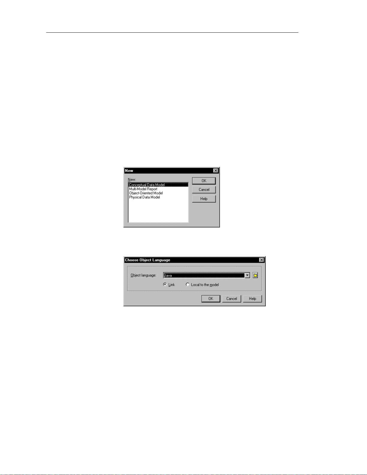
v To create an OOM:
1 Select File➤New.
or
Click the New button in the toolbar.
The New window appears.
2 Select Object-Oriented Model and click OK.
The Choose O bject Language windo w ap pears.
Every OOM is atta ched by default to one set of object language
properties. When you create a new OOM, you choose a ta rget language.
$ For more information on object la nguage properties, see the
chapter Ob ject Language Properties.
3 Select an object language from the Object language dropdown listbox.
6
Page 17
Chapter 1 Object-Oriented Model Basics
4 Click OK.
If you were working on an existing workspace, PowerDesigner opens an
new OOM. If there was no workspace open, PowerDesigner opens a new
workspace and a new OOM.
5 Select Model➤Model Properties.
or
Right-click any empty space in the diagram and select Model Properties
from the contextual menu.
The model property sheet appears.
6 Type a model name and model code.
7 Click OK.
7
Page 18

Opening an existing OOM
Opening an existing OOM
An OOM has the file extension .OOM.
v To open an existing OOM:
1 Select File➤Open.
or
Click the Open tool.
A standard Windows file selection dialog box appears.
2 Select a file with the .OOM extension.
3 Click OK.
The model window displays the selected model.
8
Page 19

Chapter 1 Object-Oriented Model Basics
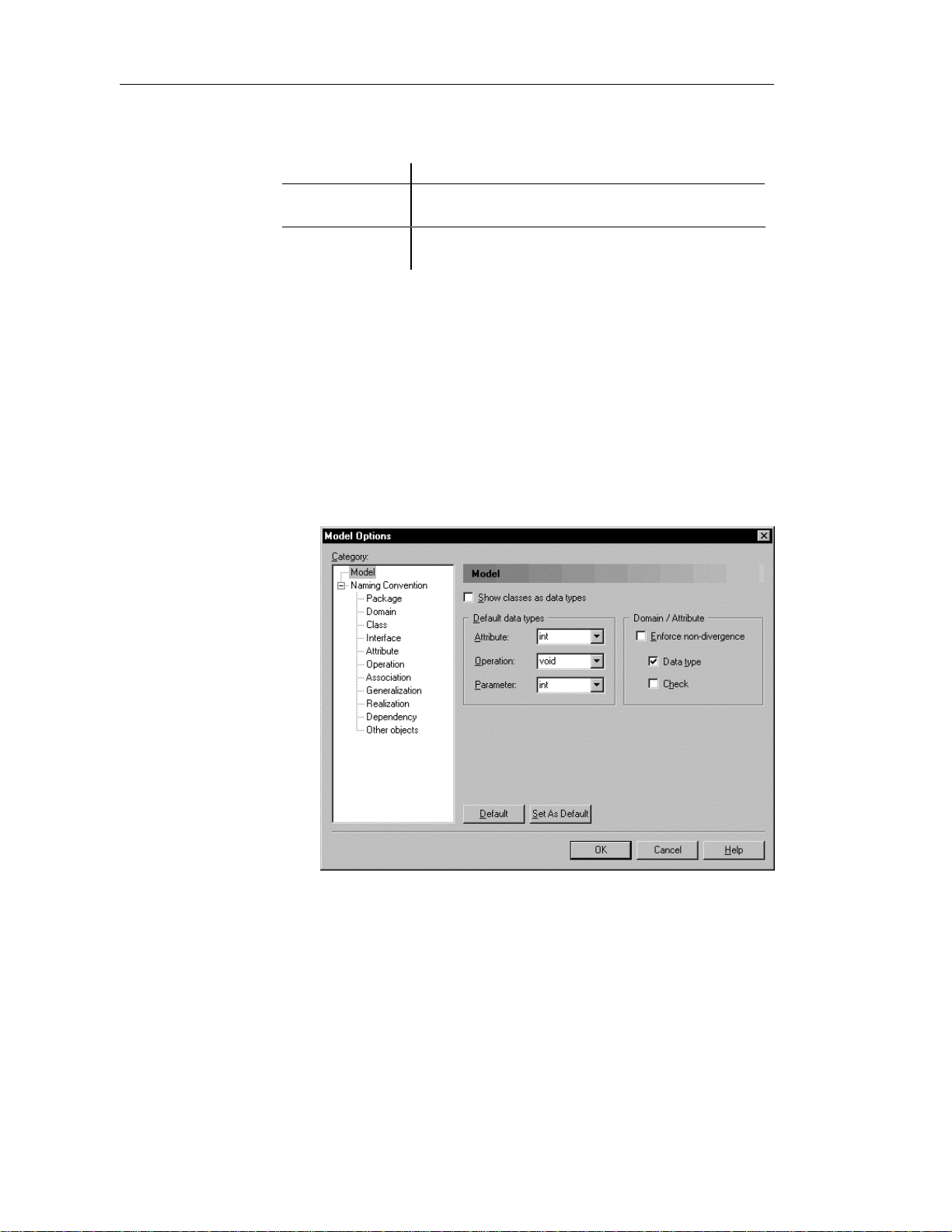
Defining OOM model options
You can set model options and naming conventions that apply to all objects
in the model. You can also set naming conventions for each type of object in
your model.
You define OOM model options from the model options dialog box.
You can set options that apply to the following OOM objects:
♦ Classes
♦ Default data types
♦ Domain/Attribute
Classes
Default data types
Domains/Attribute
You can set the following option for classes in an OOM:
Option Description
Show classes as
datatypes
Includes classes that exist in the model in the list of data
types that you can define for attributes, operations, or
parameters
The default data type is the data type that applies to attributes, operations and
parameters if no data type is selected.
You can set the following options for default data type in an OOM:
Option Description
Attribute Default
Data Type
Operation Default
Data Type
Parameter Default
Data Type
Defines the default data type for all new attributes
Defines the default return type for all new operations
Defines the default data type for all new operation
parameters
From the Model Options dialog box, you can choose to enforce nondivergence between a domain definition and the attributes using the domain,
for the following attribute properties:
Property Attributes in the domain cannot have divergent
Data type Data type, length, and precision
Check Check parameters
9
Page 20
Defining OOM model options
Your choice of whether or not to enforce domain and attribute nondivergence has the following results:
Non-divergence Result
Not enforced Attributes that are divergent from the d omain definition can
Enforced Attributes that are divergen t from the domain (for certain
If you modify domain non-divergence optio ns, these changes app l y only to
the current OOM.
$ For more information on PowerDesigner model options, see the
PowerDesigner General Features Guide.
v To define OOM model options:
1 Select Tools➤Model Options.
remain attached to the d omain
attribute properties) must be detached from the domain
or
Right-click any empty space in the diagram and select Model Options
from the contextual menu.
The Model Options dialog box opens to the model page.
10
2 Select model options in the different boxes.
3 Click OK.
Page 21

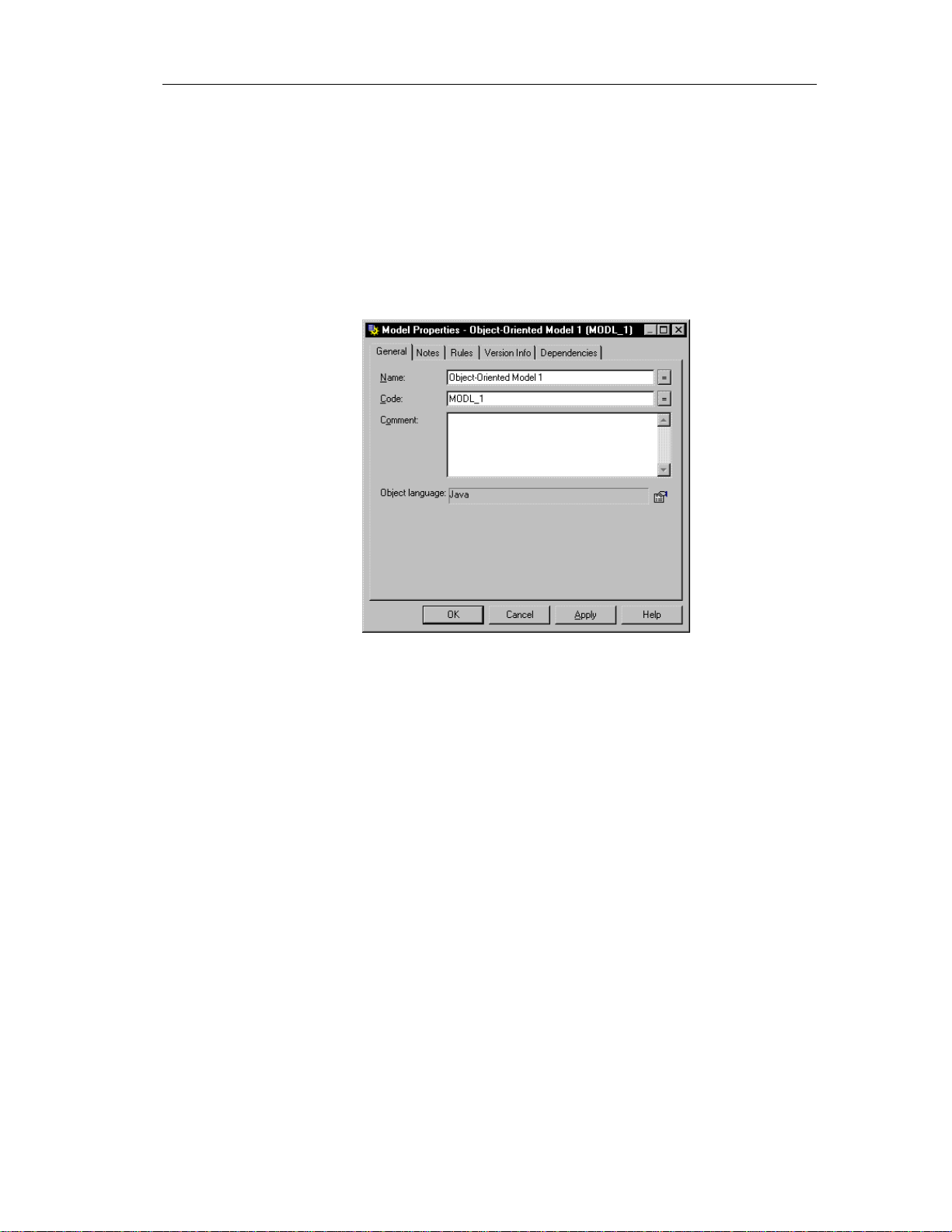
Defining OOM properties
The Model property sheet displays the definition of the current model. From
this property sheet you can modify the model definition.
A OOM has the following model properties:
Property Description Length
Name Name for the model 254
Chapter 1 Object-Oriented Model Basics
Code Code for the model. This code is generated in
database scripts
Comment Descriptive label for the model —
Object language Current object language for the model. You can
open the property sheet for the current object
language by clicking the Properties tool to the
right of the box
v To modify the model properties:
1 Select Model➤Model Properties.
or
Right click the diagram background and select Properties from the
contextual menu.
The model property sheet appears.
2 Type changes to model properties.
3 Click OK.
254
—
11
Page 22

Defining OOM properties
12
Page 23

CHAPTER 2
Building an Object-Oriented Model
About this chapter
Contents
This chapter describes how to build an Object-Oriented Model (OOM). It
explains the role of each object in an OOM and how to create and modify
objects.
Topic Page
Defining packages 14
Defining classes 17
Defining interfaces 36
Defining attributes 48
Defining identifiers 62
Defining operations 67
Defining parameters 88
Defining generalizations 91
Defining associations 97
Defining dependencies 108
Defining realizations 114
Defining domains 120
Defining check parameters 130
13
Page 24

Defining packages
Defining packages
A package is a general purpose mechanism for organizing elements into
groups.
When you are working with large models, you can split any model into
smaller subdivisions in order to avoid manipulating the entire set of data of
the model. Packages can be useful to assign portions of a model, representing
different tasks and subject areas, to different development teams.
You can create as many packages as you need in a model. The name of each
package must be unique in the model.
Package hierarchy
You can create several packages at the same hierarchical level within a
model. or decompose a package into other packages and continue this
process without limitation in decomposition depth. At each level of
decomposition you can create several diagrams.
Packages work as models, they can contain the following items:
♦ Model objects
♦ Other packages
♦ Diagrams, in order to have diffe rent views of the contents of the
$ For more information on packages, see the PowerDesigner Feature
Guide.
Package properties
Packages have properties displayed on property sheets. All packages share
the following common properties:
Property Description Length
Name Names are like titles that clearly identify the package
Code Codes are references for packages 254
package. Each package appears with a default diagram window
254
during the design process
14
Comment A comment is an optional label that describes a
package and provides more information than the name
Namespace Option that defines the package as being the area in
which the name of an object must be unique in order to
be used.
—
—
Page 25

Displaying text in package symbols
You can define the following display preferences for a package:
Preference Description
Show stereotypes When selected, displays the stereotype of th e package
Show constraints When selected, displays the constraints (types of business
rule) that are attached to the package
You modify the display preferences for a package in the Display Preferences
dialog box.
v To modify the package display preferences:
1 Select Tools➤Display Preferences.
or
Right-click the diagram background and select Display Preferences from
the contextual menu.
The Display Preferences dialog box appears.
2 Expand the Object View node in the Category list.
Chapter 2 Building an Object-Oriented Model
3 Select Package.
15
Page 26
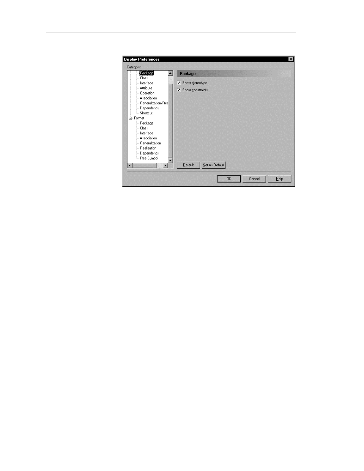
Defining packages
The package display preferences page appears.
4 Modify the package display preferences.
16
5 Click OK.
Page 27
Defining classes
A class is a description of a set of objects that have a similar structure and
behavior, and share the same attributes, operations, relationships, and
semantics. A class usually implements one or more interfaces.
Classes are the main building blocks of an OOM. Classes, and the
relationships that you create between them, form the basic structure of an
OOM. Typically, classes represent either real, abstract or conceptual things
that together make a whole or a part of a particular problem or system.
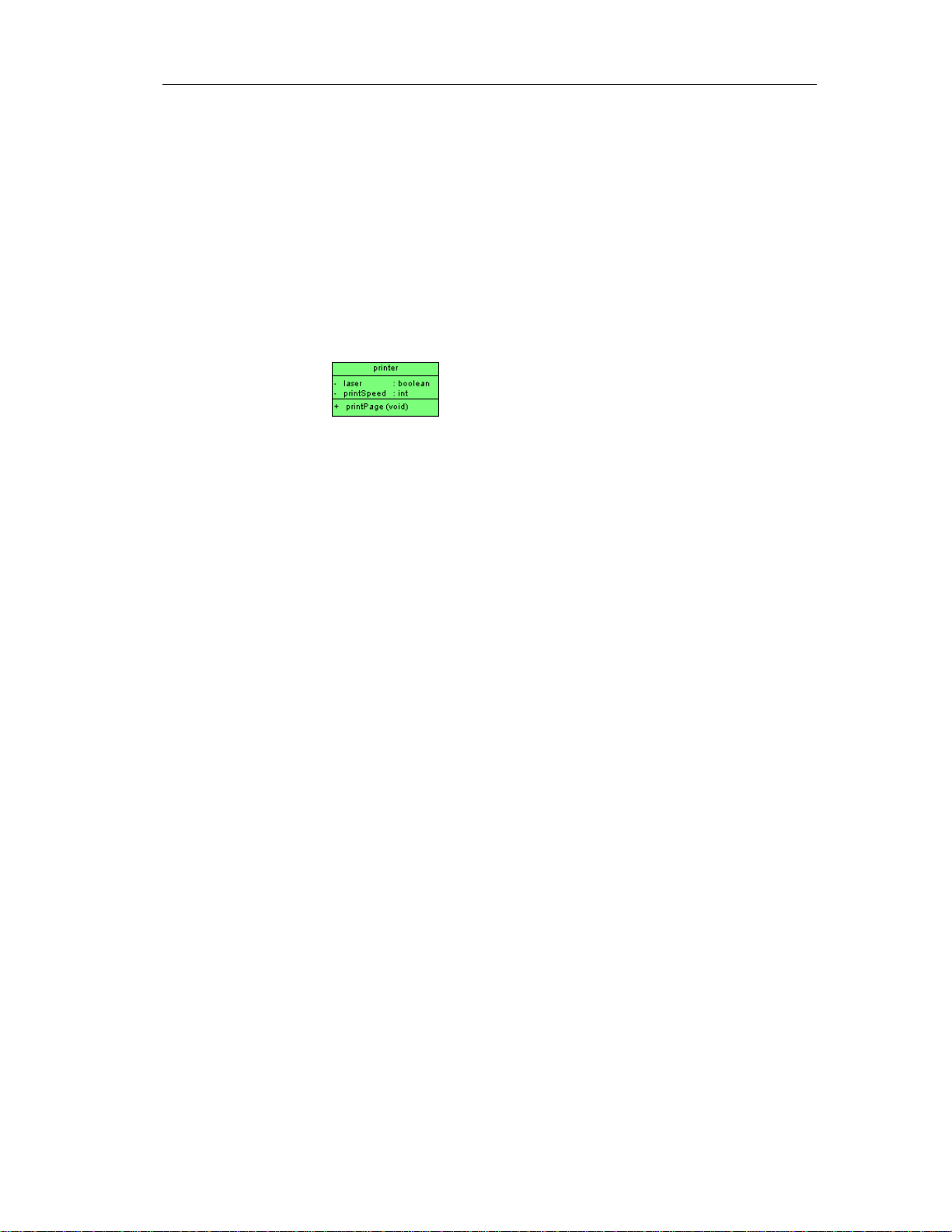
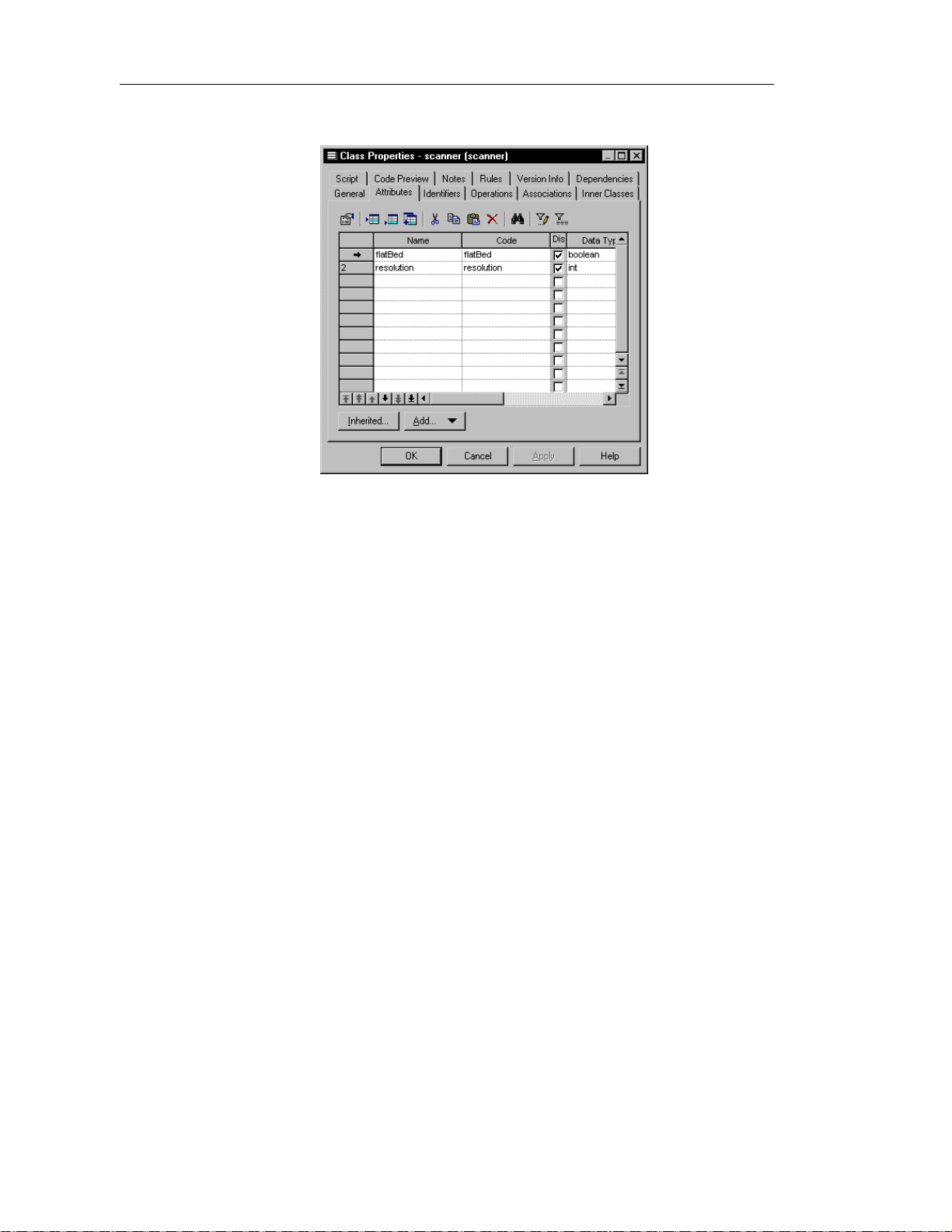
The following example shows the class Printer with its attributes and
operations.
Chapter 2 Building an Object-Oriented Model
17
Page 28

Defining classes
Class properties
A class has the following general properties:
Maximum
Property Description
Name Name of the class 254
Code Reference name for the class 254
Comment Descriptive comment for the class —
length
Stereotype Subclassification of a class derived from an existing
one. Extends the semantics of a class without
changing it's structure
Type Set of instances that share the same operations,
abstract attributes, and relationships, and semantics
Visibility Visibility of the class, whose value denotes how it
may be seen and used by other objects
Cardinality Specific number of instances that the class can have —
Persistence Lifetime of the instances of a class. An object can be
persistent or transient. If it is persistent, it continues
to exist after the process th at created it has ceased to
exist. If it is transient, t hen it ceases to exist when
the process that created it ceases to exist
Abstract Indicates that the class cannot be instantiated and
therefore has no direct instances
Final Specifies that the class cannot have any inherited
objects
Generate Indicates that the class will be automatically
included among the objects generated from the
model when you launch the generation process
—
—
—
—
—
—
—
A class definition also includes the following properties, which are defined
on associated property sheets:
18
Property Description
Attribute Defines the characteristics of a class
Operation C arries out a service that effects behavior
Rule A business rule that your business follows. Business rules guide and
document the creation of a model
Page 29

Analyzing class properties
The following class properties each have several default values from which
you can select from:
♦ Stereotype
♦ Type
♦ Visibility
♦ Cardinality
Stereotype
Stereotypes are classes that are derived from existing classes but that are
specific to a particular problem. They enable you to extend the semantics of a
class without changing its structure. In this way stereotypes must be based on
existing classes but they allow you to provide additional distinctions for these
classes. Stereotypes can be predefined or user-defined. They allow you to add
additional information that may be specific to a project or process. They may
extend the semantics, but not the structure of pre-existing classes.
Chapter 2 Building an Object-Oriented Model
Modify or creating
new stereotypes
You can modify an existing stereotype or create a new one from the object
language property sheet.
$ For more information on modifying and creating variables of an object
language, see the chapter Obj ect Language Properties.
19
Page 30

Defining classes
Default stereotypes
You can declare a class to be one of the following stereotypes:
Stereotype Description
actor Coherent set of roles that u sers of use cases play when
interacting with the use cases
enumeration List of named values used as the range of a particular
attribute type
exception Exception class. Used mostly in relation to error
messages
implementationClass Class whose in stances are statically typed, and that
defines the physical data structure and methods of a class
as implemented in traditional programming languages
process Heavyweight flow that can execute concu rrently with
other processes
signal Specification of an asynchronous stimulus communicated
between instances
thread Lightweight flow that can execute concurren tly with other
threads within the same process. Usually executes inside
the address space of an en cl osing process
type Abstract class used only to specify the structure and
behavior of a set of objects, not the implementation
utility Class that has no instances
Type
20
You can declare a class to be one of the following types:
♦ Business Object
♦ Class
♦ Storage
♦ Utility
♦ Visual Object
♦ JavaBean
Page 31

Visibility
Cardinality
Chapter 2 Building an Object-Oriented Model
The visibility of a class refers to the way in which it can be seen by other
objects. A class that is visible to another object may influence the structure or
behavior of the object, or similarly, its own properties may be affected by the
other object.
Property Visible
Private Only to the class itself
Protected Only to the class and its inherited objects
Package To all objects cont ained within the same package
Public To all objects in the model
The cardinality of a class specifies the number of instances that the class can
have.
Cardinality Number of instances
0..0 None
Creating a class
0..1 None or one
0..* None to an unlimited number
1..1 One to one
1..* One to an unlimited number
* Unlimited number
There are three ways to create a class:
♦ Create a class symbol in the Browser
♦ Add a new class to the list of classes
♦ Create a class symbol directly in a diagram
21
Page 32
Defining classes
Creating a class from the Browser
v To create a class from the Browser:
1 Right-click the Classes category in the Browser.
2 Select New from the contextual menu.
The property sheet of the class appears.
3 Type a class name and a class code.
4 Click OK.
A new class is created in the Classes category.
Creating a class from the list of classes
v To create a class by inserting it in the list:
1 Select Model➤Classes.
The list of classes appears.
Accessing the list of classes
The list of classes is accessible only from a diagram. If the current
diagram is of a package, the list contains all the classes that exist in
the package. If the current diagram is of the model, the list contains
all the classes that exist in the model.
22
2 Click a blank line in the list.
or
Click the Add a Row tool.
An arrow appears at the beginning of the line.
3 Type a name and code for the class.
4 Select a stereotype from the Stereotype dropdown listbox.
5 Select a visibility from the Visibility dropdown listbox.
6 Click OK.
A symbol for this class is inserted in the current model.
Page 33

Creating a class from a diagram
v To create a class in a diagram:
1 Click the Class tool in the palette toolbar.
2 Click anywhere in the diagram.
The following symbol appears at the click position:
At creation, a class is named Classn, where n is a number assigned in the
order of the creation of objects.
3 Click the Pointer tool in the palette toolbar.
4 Double-click the new class symbol in the diagram.
The class property sheet appears.
5 Type a class name and a class code.
6 Click OK.
The newly created class is visible in the Browser.
Chapter 2 Building an Object-Oriented Model
Inner classes
An inner class is a class that is defined within another (outer) class or
interface. Inner classes are commonly used in Java. They help you to improve
the overall visibility of your model by allowing you to group together classes
that logically belong together.
You can add inner classes to a class or an interface.
23
Page 34
Defining classes
Attaching an inner class to a class
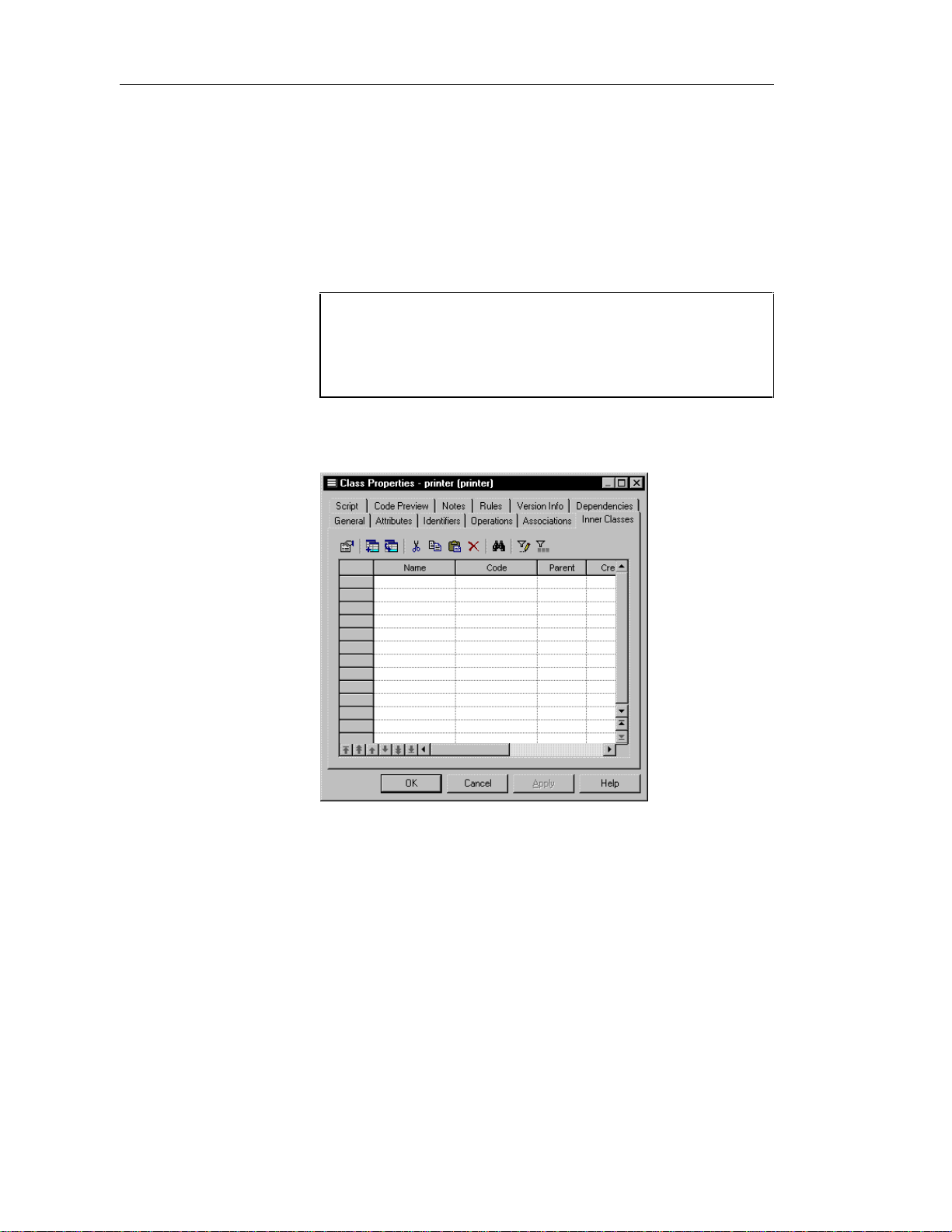
You attach an inner class to a class (or interface) from the Inner Classes page
of the class (or interface) property sheet.
v To declare an inner class within a class:
1 Double-click a class in the model.
The class property sheet opens to the General page.
Opening property sheets at last accessed page
Property sheets open to the General page by default. However, you
can choose to open property sheets at the last page accessed by
selecting Tools➤Options➤Dialog, and selecting the option Keep
Last Tab in the Property Sheets groupbox.
2 Click the Inner Classes tab.
The Inner Classes page appears.
24
3 Click the Attach inner class tool.
A selection window appears.
4 Click the classes you want to attach as inner classes in the current class.
5 Click OK.
Page 35
Chapter 2 Building an Object-Oriented Model
The classes appear in the list of inner classes for the current class, and
the definition of the classes are added to the current class definition.
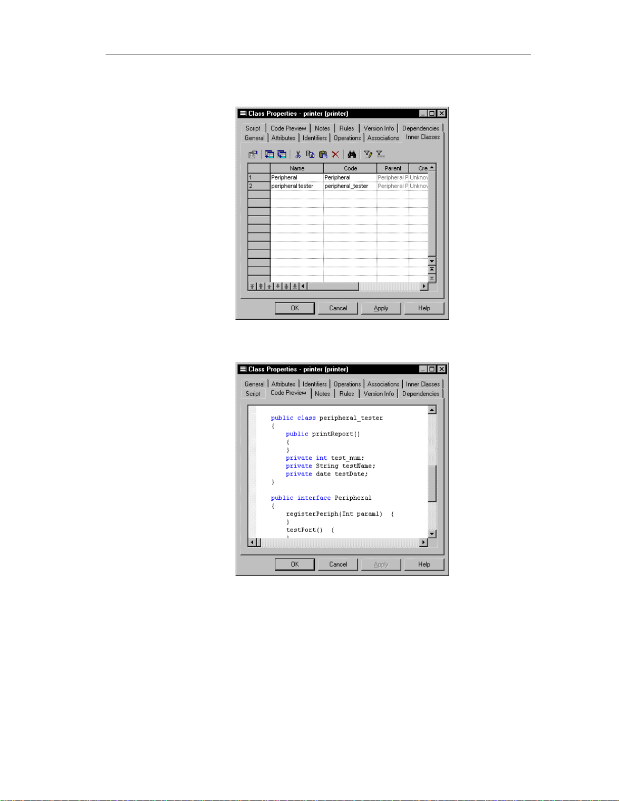
6 Click the Code Preview tab to visualize the inner class definitions within
the current class:
7 Click OK.
25
Page 36

Defining classes
Detaching an inner class from a class
Once you have attached an inner class to a class, to remove its declaration
from the class you must use detach it.
v To detach an inner class from a class:
1 Double-click a class in the model.
The class property sheet opens to the General page.
Opening property sheets at last accessed page
Property sheets open to the General page by default. However, you
can choose to open property sheets at the last page accessed by
selecting Tools➤Options➤Dialog, and selecting the option Keep
Last Tab in the Property Sheets groupbox.
2 Click the Inner Classes tab.
The Inner Classes page appears.
26
3 Select an inner class from the list of inner classes.
4 Click the Detach inner class tool.
The inner class definition is detached from the current class definition
and is removed from the list of inner classes of the current class.
5 Click OK.
Page 37

Chapter 2 Building an Object-Oriented Model
Classifiers
A classifier, in UML terminology, is a mechanism that has structural
(attributes) and behavioral (operations) features. A class is the most
important classifier, but all objects that can have instances, such as interfaces
or associations, are classifiers.
Modifying class properties
There are two approaches to modifying class properties:
♦ Modify the property sheet of the class
♦ Modify an entry in the list of classes
Modifying class properties from its property sheet
The class property sheet displays the definition of the class, which you can
modify.
v To modify class properties from its property sheet:
1 Double-click the class in the Browser.
or
Double-click the class in the list of classes.
or
Double-click the class in a diagram.
27
Page 38

Defining classes
The class property sheet appears.
2 Type or select class properties.
or
Click on a page tab.
Type or select class properties as required.
3 Click OK.
Modifying class properties from the list of classes
The list of classes includes all classes attached to the current model or
package. You can modify the class properties from the list.
v To modify class properties from the list of classes:
1 Select Model➤Classes.
The list of classes appears.
2 Click the class that you want to modify.
28
Page 39
Chapter 2 Building an Object-Oriented Model
An arrow appears at the beginning of the line.
3 Modify any of the properties of the class directly in the list.
4 Click OK.
Adding objects to a class
You can add an object to a class, that already exists in the model, but which
belongs to another class.
You can add the following objects to an object:
Object Description
Attribute Named property of a class that defines the characteristics of a
Operation Implementation of a service that can be requested from any
Business rule Written statement specifying what the information system must
You add an object to a class from the list in the page corresponding to the
object, in the class property sheet.
When you add an object to a class in this way, you in fact create a copy of the
object. The new object exists as a unique object, and you can then make
changes to it as you would to any object in the model.
class
object of the class in order to affect behavior
do or how it must be structured to support business needs
29
Page 40
Defining classes
Adding an attribute to a class
An attribute is a named property of an object that defines the characteristics
of the object.
You can add attributes that already exist in the model and which belong to
other objects.
v To add an attribute to a class:
1 Double-click a class in the model.
The class property sheet appears.
2 Click the Attributes tab.
The Attributes page appears.
30
3 Click the Add Attributes tool.
Page 41

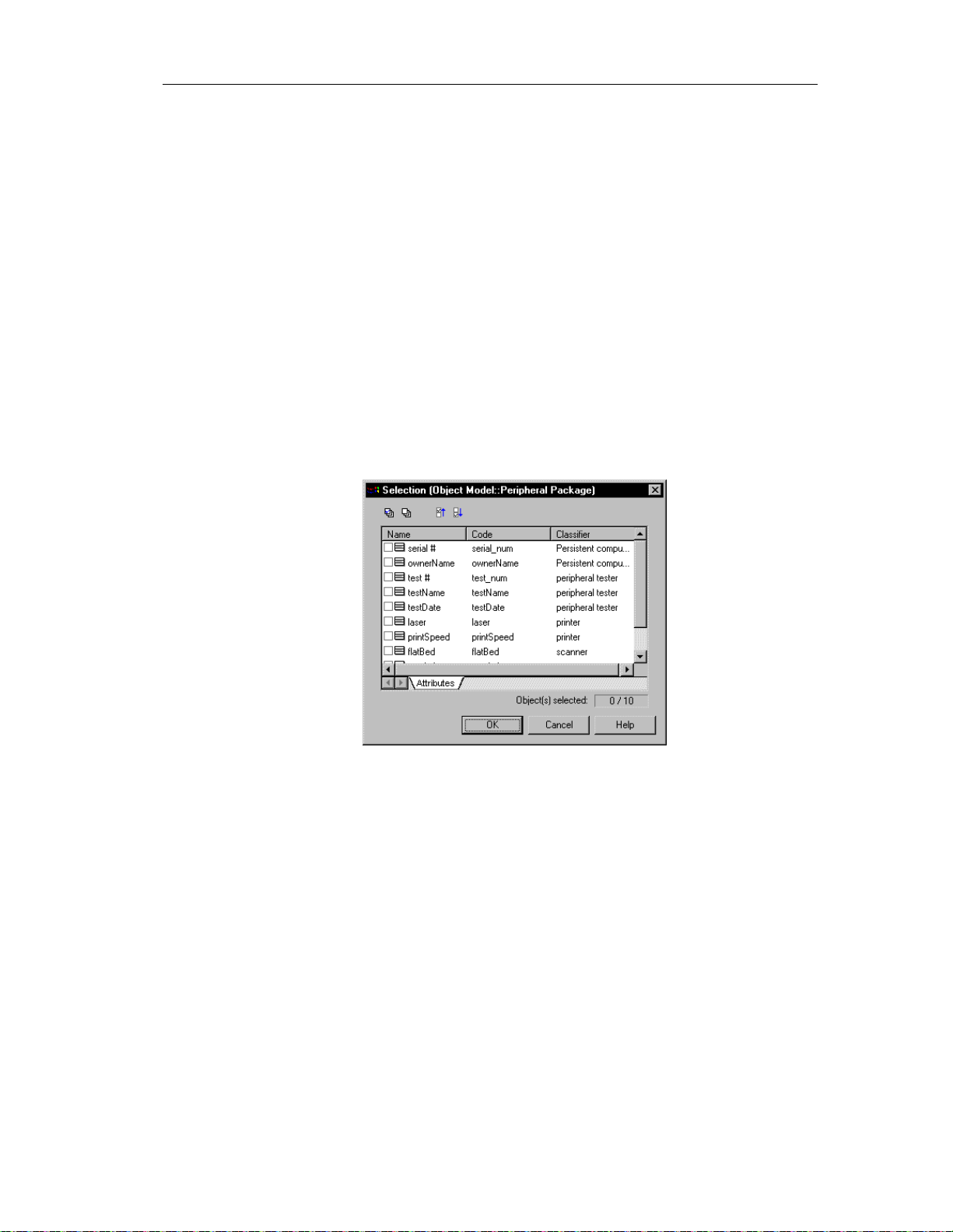
Chapter 2 Building an Object-Oriented Model
The Selection window appears. It contains a list of all the attributes that
exist in the model, with the exception of those that already belong to the
class.
4 Select the attributes that you want to add to the class.
or
Use the Select All tool to add all the attributes in the list to the class.
5 Click OK.
The attributes are added to the class and appear at the end of the list.
6 Click OK.
Adding an operation to a cl ass
An operation is the implementation of a service that can be requested from
any object of the class in order to affect behavior.
You can add operations that already exist in the model and which belong to
other objects.
v To add an operation to a class:
1 Double-click a class in the model.
The class property sheet appears.
2 Click the Operations tab.
31
Page 42

Defining classes
The Operations page appears.
3 Click the Add Operations tool.
32
The Selection window appears. It contains a list of all the operations that
exist in the model, with the exception of those that already belong to the
class.
4 Select the operations that you want to add to the class.
5 Click OK.
Page 43
Chapter 2 Building an Object-Oriented Model
The operations are added to the class and appear in the list of operations
for the class.
6 Click OK.
Preview the code of a class or an interface
You can preview the code of a class or an interface in the Code Preview page
of the Property sheet of a class or an interface. You cannot edit the code in
this window.
v To preview the code of a class:
1 Double-click a class in the model.
The class property sheet appears.
2 Click the Code Preview tab.
The Code Preview page appears.
3 Click OK.
33
Page 44

Defining classes
Displaying text in class symbols
You can define the following display preferences for a class:
Preference Description
Show attributes Displays all the attributes of the class, or limits the number
displayed to a maximum that you specify in the Limit box
Show operations Displays all the operations of the class, or limits the number
displayed to a maximum that you specify in the Limit box
Show stereotypes When selected, displays the stereotype of the class
Show constraints When selected, displays the constraints (types of business
rule) that are attached to the class
You modify the display preferences for a class in the Display Preferences
dialog box.
v To modify the class display preferences:
1 Select Tools➤Display Preferences.
or
Right-click the diagram background and select Display Preferences from
the contextual menu.
34
The Display Preferences dialog box appears.
2 Expand the Object View node in the Category list.
3 Select Class.
Page 45

Chapter 2 Building an Object-Oriented Model
The class display preferences page appears.
4 Modify the class display preferences.
5 Click OK.
35
Page 46

Defining interfaces
Defining interfaces
An interface is a type of class that is similar to a class but which is used to
implement the specification of an abstraction of a class. An interface is a
collection of operations used to specify the externally visible behavior of a
class. It has no implementation of its own.
A class that implements all the operations in an interface is said to realize the
interface. A class that requires one or more operations in an interface is said
to use the interface. The interface includes the signatures of the operations of
the class. Usually, an interface specifies only a limited part of the behavior of
a class. A class can implement one or more interfaces.
The following example shows a Name (interface) that realizes the action
GetName for an Employee (class).
Interface properties
An interface has the following properties:
Property Description
Name Name of the interface 254
Code Reference name for the interface 254
Comment Descriptive comment for the interface —
Stereotype Subclassification of an interface derived from an
Visibility Visibility of the interface, whose value denotes
Generate Indicates that the class will be automatically
36
Maximum
length
—
existing one. Extends the semantics of an interface
without changing it's structure
—
how it may be seen outside its enclosing name
space
—
included among the objects generated from the
model when you launch the generation process
Page 47

An interface definition also includes the following properties, which are
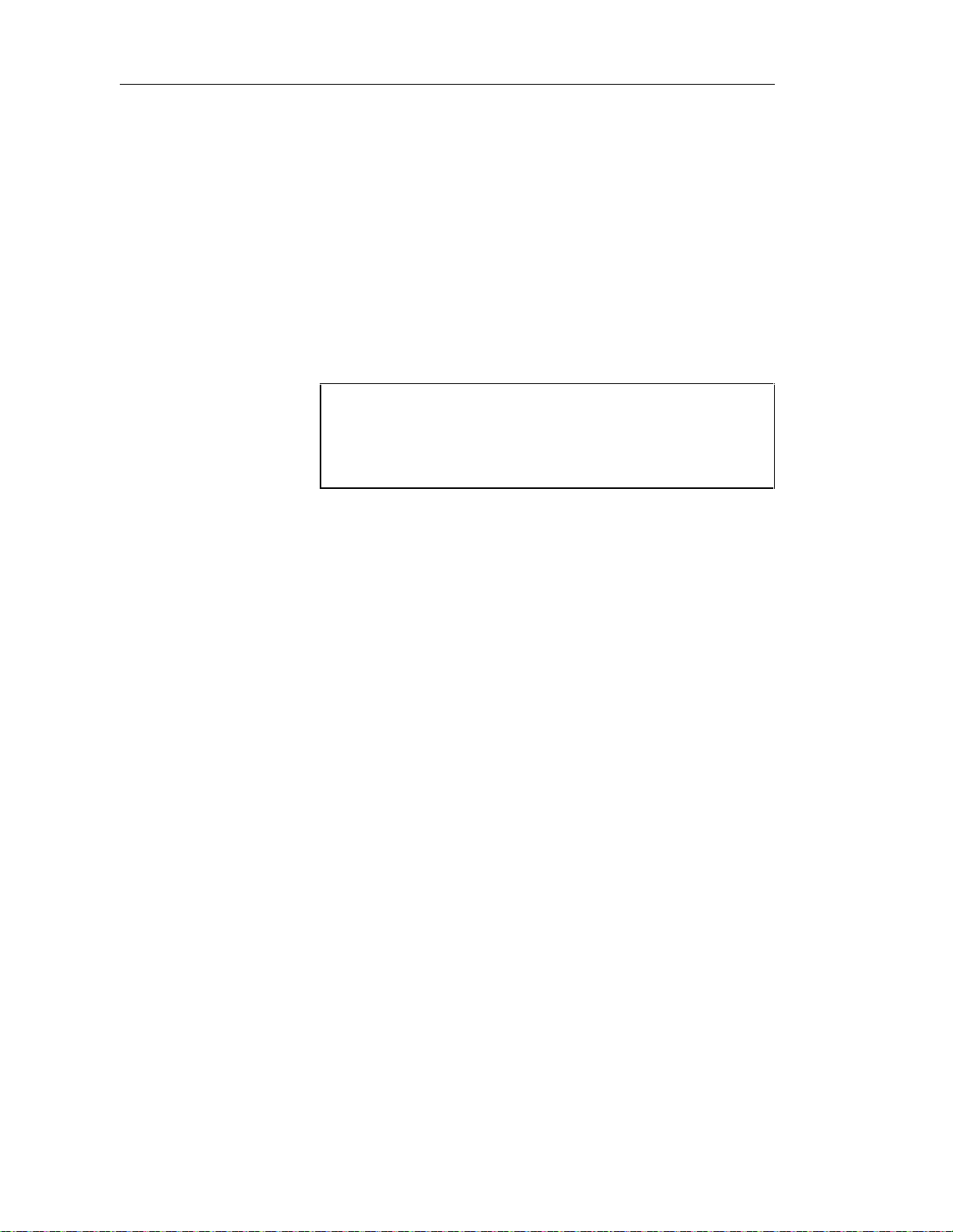
defined on associated property sheets:
Property Description
Attribute Defines the characteristics of an in terface
Operations Carries out a service that effects behavior
Business rules A rule that your business follows. Business rules guide and
document the creation of a model
Analyzing interface properties
Chapter 2 Building an Object-Oriented Model
Visibility
The visibility of an interface refers to the way in which it can be seen by
other objects. An interface that is visible to another object may influence the
structure or behavior of the object, or similarly, its own properties may be
affected by the other object.
Property Visible
Private Only to the interface itself
Protected Only to the i nterface and its inherited objects
Package To all objects contained within the same package
Public To all objects in workspace
Creating an interface
There are three ways to create an interface:
♦ Create an interface symbol in the Browser
♦ Create an interface symbol directly in a diagram
♦ Add a new interface to the list of classes
Creating an interface from the Browser
v To create an interface from the Browser:
1 Right-click the Interfaces category in the Browser.
2 Select New from the contextual menu.
37
Page 48
Defining interfaces
The property sheet of the interface appears.
3 Type an interface name and an interface code.
4 Click OK.
A new interface is created in the Interfaces category.
Creating an interface from the list of interfaces
v To create an interface by inserting it in the list:
1 Select Model➤Interfaces.
The list of interfaces appears.
Accessing the list of interfaces
The list of interfaces is accessible only from a diagram. If the current
diagram is of a package, the list contains all the interfaces that exist in
the package. If the current diagram is of the model, the list contains
all the interfaces that exist in the model.
2 Click a blank line in the list.
or
Click the Add a Row tool.
An arrow appears at the beginning of the line.
3 Type a name and code for the interface.
4 Select a stereotype from the Stereotype dropdown listbox.
5 Select a visibility from the Visibility dropdown listbox.
6 Click OK.
A symbol for this interface is inserted in the current model.
Creating an interface from a diagram
v To create an interface in a diagram:
1 Click the Interface tool in the palette toolbar.
2 Click anywhere in the interface diagram.
38
Page 49

The following symbol appears at the click position:
At creation, an interface is named Intfn, where n is a number assigned in
the order of the creation of objects.
3 Click the Pointer tool in the palette toolbar.
4 Double-click the new interface symbol in the diagram.
The interface property sheet appears.
5 Type an interface name and an interface code.
6 Click OK.
The newly created interface is visible in the Browser.
Modifying interface properties
There are two approaches to modifying interface properties:
♦ Modify an interface property sheet
Chapter 2 Building an Object-Oriented Model
♦ Modify an entry in the list of interface
Modifying interface properties from its property sheet
The interface property sheet displays the definition of an interface, which you
can modify.
v To modify interface properties from its property sheet:
1 Double-click the interface in the Browser.
or
Double-click the interface in the list of interfaces.
or
Double-click the interface in a diagram.
39
Page 50
Defining interfaces
The interface property sheet opens to the General page.
Opening property sheets at last accessed page
Property sheets open to the General page by default. However, you
can choose to open property sheets at the last page accessed by
selecting Tools➤Options➤Dialog, and selecting the option Keep
Last Tab in the Property Sheets groupbox.
2 Type or select interface properties.
or
Click on a page tab.
Type or select interface properties as required.
3 Click OK.
Modifying interface properties from the list of interfaces
The list of interfaces includes all interfaces attached to the current model.
You can modify the interface properties from the list.
v To modify interface properties from the list of interfaces:
1 Select Model➤Interfaces.
40
Page 51

Chapter 2 Building an Object-Oriented Model
The list of interfaces appears.
2 Click the interface that you want to modify.
An arrow appears at the beginning of the line.
3 Modify any of the properties of the interface directly in the list.
4 Click OK.
Adding inner classes to an interface
An inner class is a class definition that is defined within another (outer) class
definition. Inner classes are commonly used in Java. They help you to
improve the overall visibility of your model by allowing you to group
together classes that logically belong together.
You can add inner classes to a class or an interface.
$ For more information on inner classes, see the section Inner classes.
Adding objects to an interface
You can add an object to an interface, that already exists in the model, but
which belongs to anot her object.
41
Page 52

Defining interfaces
You can add the following objects to an interface:
Object Description
Attribute Named property of an interface that defines th e characteristics of
Operation Implementation of a service that can be requested from any
Business rule Written statement specifying what the information system must
You add an object to an interface from the list in the page corresponding to
the object, in the interface property sheet.
When you add an object to an interface in this way, you in fact create a copy
of the object. The new object exists as a unique object, and you can then
make changes to it as you would to any object in the model.
Adding an attribute to an interface
An attribute is a named property of an object that defines the characteristics
of the object.
an interface
object of the interface in order to affect behavior
do or how it must be structured to support business needs
42
You can add attributes to an interface that already exist in the model and
which belong to other objects.
v To add an attribute to an interface:
1 Double-click an interface in the model.
The interface property sheet appears.
2 Click the Attributes tab.
Page 53

Chapter 2 Building an Object-Oriented Model
The Attributes page appears.
3 Click the Add Attributes tool.
The Selection window appears. It contains a list of all the attributes that
exist in the model, with the exception of those that already belong to the
interface.
4 Select the attributes that you want to add to the interface.
5 Click OK.
The attributes are added to the interface and appear in the list of
attributes for the interface.
43
Page 54

Defining interfaces
6 Click OK.
Adding an operation to an interface
An operation is the implementation of a service that can be requested from
any object of the class in order to affect behavior.
You can add operations that already exist in the model and which belong to
other objects.
v To add an operation to an interface:
1 Double-click an interface in the model.
The interface property sheet appears.
2 Click the Operations tab.
The Operations page appears.
44
3 Click the Add Operations tool.
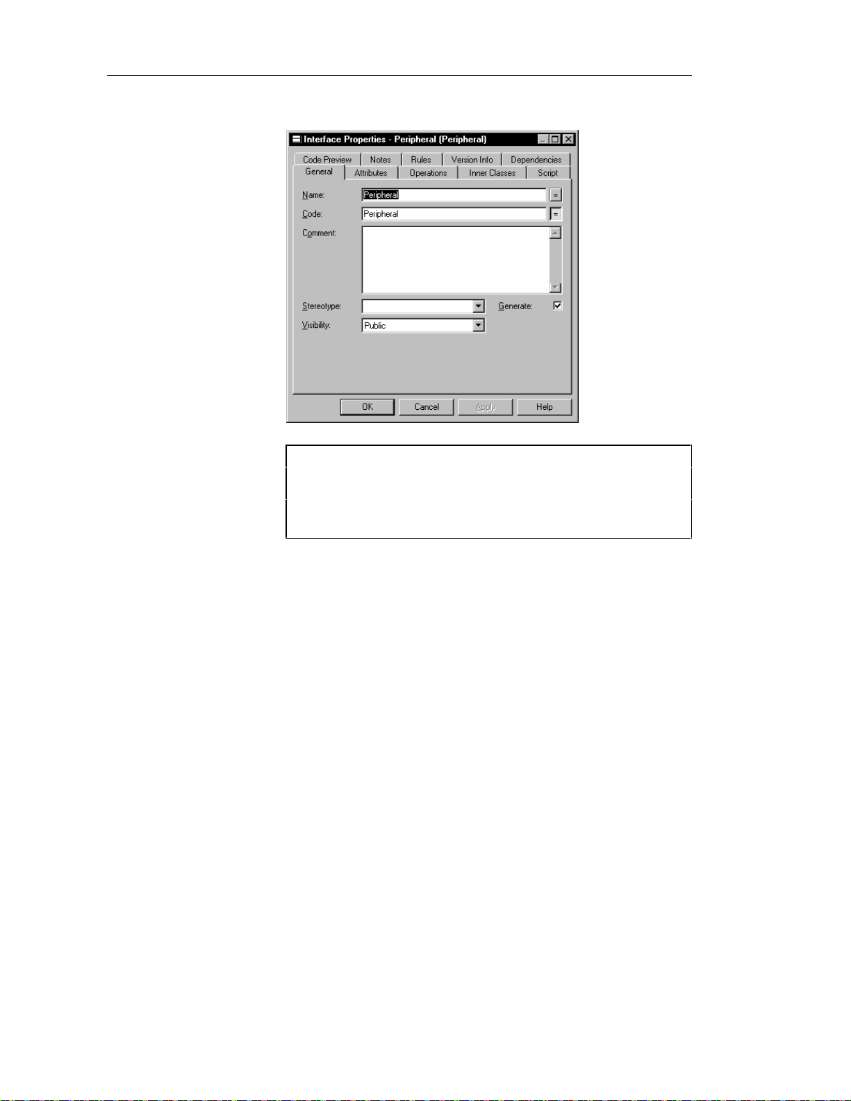
Page 55
Chapter 2 Building an Object-Oriented Model
The Selection window appears. It contains a list of all the operations that
exist in the model, with the exception of those that already belong to the
interface.
4 Select the operations that you want to add to the interface.
5 Click OK.
The operations are added to the interface and appear in the list of
operations for the interface.
6 Click OK.
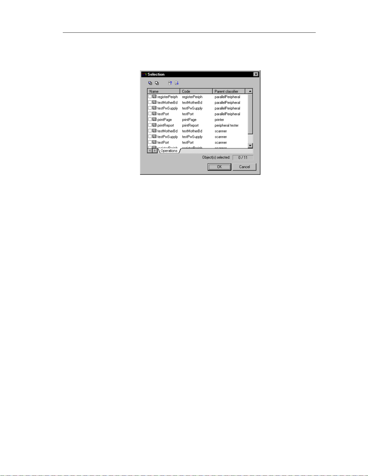
Preview the code of an interface
You can preview the code of an interface or a class in the Code Preview page
of the Property sheet of an interface. You cannot edit the code in this
window.
v To preview the code of an interface:
1 Double-click an interface in the model.
The interface property sheet appears.
2 Click the Code Preview tab.
45
Page 56
Defining interfaces
The Code Preview page appears.
3 Click OK.
Displaying text in interface symbols
You can define the following display preferences for an interface:
Preference Description
Show attributes Displays all the attributes of the interface, or limits t he
number displayed to a maximum that you specify in the Limit
box
Show operations Displays all the operations of the interface, or limits the
number displayed to a maximum that you specify in the Limit
box
Show stereotypes When sel ect ed, displays the stereotype of the interface
Show constraints When selected, displays the constraints (types of business
rule) attached to the interface
You modify the display preferences for an interface in the Display
Preferences dialog box.
46
Page 57

Chapter 2 Building an Object-Oriented Model
v To modify the interface display preferences:
1 Select Tools➤Display Preferences.
or
Right-click the diagram background and select Display Preferences from
the contextual menu.
The Display Preferences dialog box appears.
2 Expand the Object View node in the Category list.
3 Select Interface.
4 Modify the interface display preferences.
5 Click OK.
47
Page 58

Defining attributes
Defining attributes
Attributes define the characteristics of a class. A class may have none or
several attributes. An attribute is a named property of a class that describes
the range of values that instances of the property may hold. Each object in a
class has the same attributes, but the values of the attributes may be different.
Attribute names within a class must be unique. You can give identical names
to two or more attributes only if they exist in different classes.
You can create attributes for the following objects of an OOM:
♦ Class
♦ Interface
You can attach attributes to an Identifier.
48
Page 59

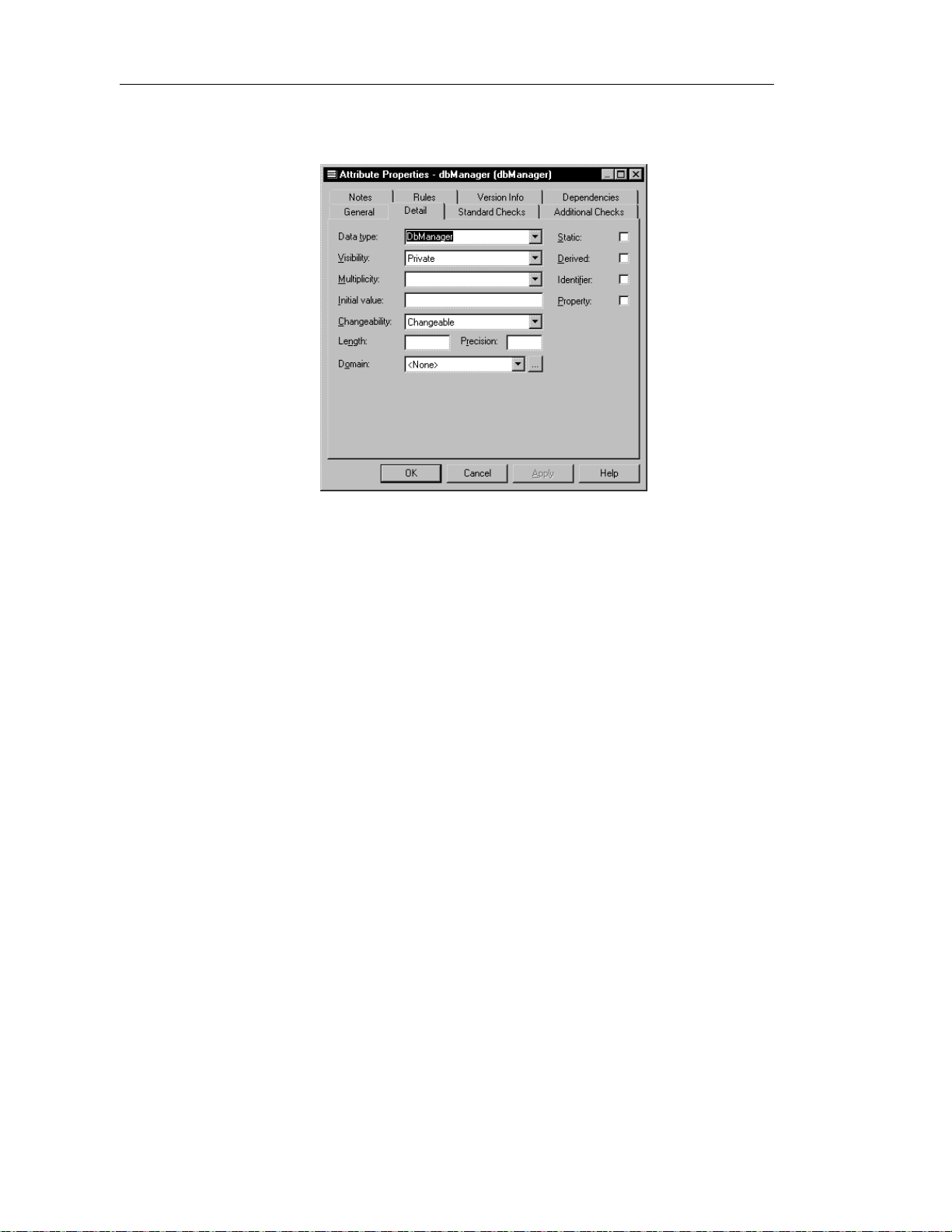
Attribute properties
An attribute has the following properties:
Property Description
Parent Object to which the attribute belongs to 254
Name Name of the attribute 254
Code Reference name for the attribute 254
Comment Descriptive comment for the attribute —
Chapter 2 Building an Object-Oriented Model
Maximum
length
Stereotype Subclassification of an attribute derived from an
existing one. Extends the semantics of an attribute
without changing it's structure
Data Type Set of instances that share the same operations,
abstract attributes, and relationships, and
semantics
Visibility Visibility of the attribute, whose value denotes
how it may be seen outside its enclosing name
space
Multiplicity Specification of the range of allowable
cardinalities that a set may assume
Initial value Initial value of the attribute —
Changeability Specifies that the value of the attribute cannot be
modified once the object has been initialized
Length Maximum number of characters —
Precision Number of places after the decimal point, for data
values that can take a deci mal p oint
Domain Name of the associated domain —
Static Defines the attribute as static, meaning it cannot
be modified
Derived Indicates that the attribute is a calculated formula —
—
—
—
—
—
—
—
Identifier When selected, converts the attribute into a
primary key after generation of the OOM to a
PDM
Property When selected, converts the attribute into a
property after generating PowerBuilder objects
from the OOM
—
—
49
Page 60

Defining attributes
An attribute definition also includes business rules, which are defined on
associated property sheets.
Analyzing attribute properties
The following attribute properties each have several default values from
which you can select from:
♦ Data Type
♦ Visibility
♦ Multiplicity
Data Type
You can select one of the following instances as a data type for an attribute:
Boolean
Byte
Char
Double
Float
Int
Long
Short
Visibility
50
Property Visible
Private Only to the attribute itself
Protected Only to the attribute and its inherited objects
Package To all objects contained within the same package
Public To all objects
Page 61

Multiplicity
The cardinality of each of an attribute is called the multiplicity.
Cardinality Number of instances in relation
0..0 None
0..1 None or one
0..* None to infinity
1..1 One to one
1..* One to infinity
* Infinity
You can change the default format of cardinalities from the registry:
Creating an attribute
Chapter 2 Building an Object-Oriented Model
HKEY_CURRENT_USER\Software\Sybase\PowerDesigner
7\ModelOptions\Cld
MultiplicityNotation = 1 (0..1) or 2 (0,1)
There are three ways to create an attribute:
♦ Create an attribute symbol in the Browser
♦ Add a new attribute to the list of attributes
♦ Create an attribute from a class in a diagram
Creating an attribute from the Browser
v To create an attribute from the Browser:
1 Right-click the Attributes category in the Browser.
2 Select New from the contextual menu.
51
Page 62

Defining attributes
The property sheet of the attribute appears.
3 Type an attribute name and an attribute code.
4 Click OK.
A new attribute is created in the Attributes category.
Creating an attribute from t he l ist of attributes
v To create an attribute by inserting it in the list:
1 Select Model➤Attributes.
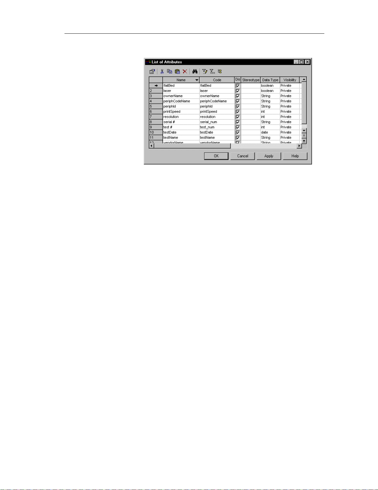
The list of attributes appears.
Accessing the list of attributes
The list of attributes is accessible only from a diagram. If the current
diagram is of a package, the list contains all the attributes that exist in
the package. If the current diagram is of the model, the list contains
all the attributes that exist in the model.
2 Click a blank line in the list.
or
Click the Add a Row tool.
An arrow appears at the beginning of the line.
52
Page 63

Chapter 2 Building an Object-Oriented Model
3 Type an attribute name and an attribute code.
4 Click the Stereotype column.
5 Select a stereotype from the Stereotype dropdown listbox.
or
Type a stereotype in the Stereotype column.
6 Click the Data Type column.
7 Select a data type from the Data Type dropdown listbox.
or
Type a data type in the Data Type column.
8 Click the Visibility column.
9 Select a value from the Visibility dropdown listbox.
10 Click the Multiplicity column.
11 Select a cardinality value from the Multiplicity dropdown listbox.
or
Type a cardinality value in the Multiplicity column.
12 Type the name of the class to which you want to associate the attribute in
the Parent column.
13 Click OK.
The attribute is created for the class.
Creating an attribute from a class in a diagram
You can create an attribute from a class or an interface in a diagram in the
same way.
v To create an attribute from a class in a diagram:
1 Double-click a class in the model.
The class property sheet appears.
2 Click the Attributes tab.
53
Page 64
Defining attributes
The Attributes page appears. It lists attributes defined for the class.
3 Click a blank line in the list.
or
Click the Add a Row tool.
An arrow appears at the beginning of the line.
4 Type an attribute name and an attribute code.
5 Click OK.
The attribute is created for the class and appears in the list of attributes
for the class.
6 Click OK.
Modifying attribute properties
There are two approaches to modifying attribute properties:
♦ Modify the property sheet of an attribute
♦ Modify an entry in the list of attributes
54
Page 65

Chapter 2 Building an Object-Oriented Model
Modifying attribute properties from its property sheet
The attribute property sheet displays the definition of the attribute, which you
can modify.
v To modify attribute properties from its property sheet:
1 Double-click the attribute in the model.
The attribute property sheet appears.
Opening property sheets at last accessed page
Property sheets open to the General page by default. However, you
can choose to open property sheets at the last page accessed by
selecting Tools➤Options➤Dialog, and selecting the option Keep
Last Tab in the Property Sheets groupbox.
2 Type or select attribute properties as required.
3 Click on the Detail tab.
55
Page 66
Defining attributes
The general properties of the attribute, in addition to those on the general
page, appear.
4 Type or select attribute properties as required.
5 Click OK.
Modifying attribute properties from the list of att r i but es
The list of attributes includes all attributes attached to the current model. You
can modify the attribute properties from the list.
v To modify attribute properties from the list of attributes:
1 Select Model➤Attributes.
56
Page 67
Chapter 2 Building an Object-Oriented Model
The list of attributes appears.
2 Click the attribute that you want to modify.
An arrow appears at the beginning of the line.
3 Modify any of the properties of the attribute directly in the list.
4 Click OK.
Attaching an attribute to a domain
If you attach an attribute to a domain, the domain supplies the data type and
related data characteristics. It may also indicate check parameters, and
business rules.
v To attach an attribute to a domain:
1 Double-click a class in the model.
The class property sheet appears.
2 Click the Attributes tab.
The Attributes page appears listing attributes associated with the class.
3 Click an attribute in the list.
An arrow appears at the beginning of the line.
4 Click the Properties tool.
or
Double click the arrow at the beginning of the line.
57
Page 68
Defining attributes
The attribute property sheet opens to the General page.
Opening property sheets at last accessed page
Property sheets open to the General page by default. However, you
can choose to open property sheets at the last page accessed by
selecting Tools➤Options➤Dialog, and selecting the option Keep
Last Tab in the Property Sheets groupbox.
5 Click the Detail tab.
58
6 Select a domain from the Domain dropdown listbox at the bottom of the
dialog box.
7 Click OK.
You return to the Attributes page. In the Data Type attribute, the
domain’s data type replaces the data type previously defined for the
attribute.
8 Click OK.
Page 69
Chapter 2 Building an Object-Oriented Model
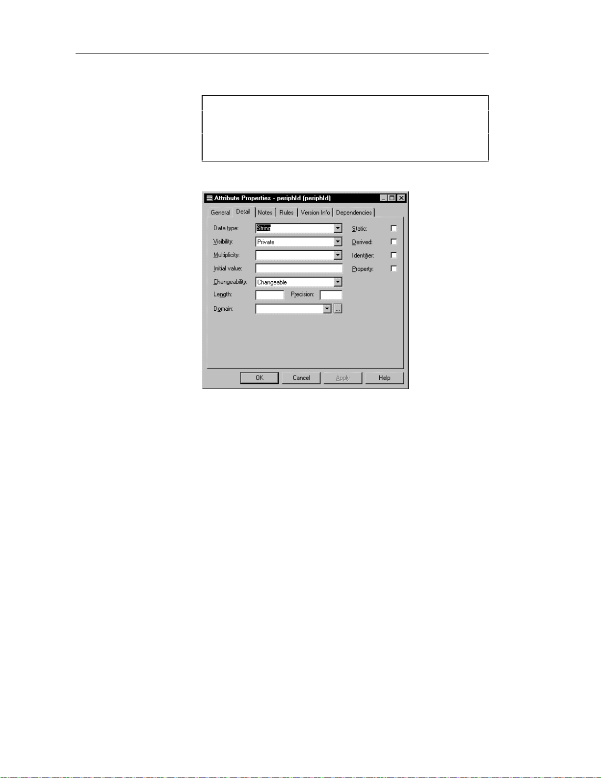
Copying an attribute to another class
You can copy an attribute from one class and add it to another class. If the
class already contains an attribute with the same name or code as the copied
attribute, the copied attribute is renamed. For example the attribute
PERIPHLD is renamed PERIPHLD2 when it is copied to a class which
already contains an attribute PERIPHLD.
v To copy an attribute to another class:
1 Double-click a class in the model.
The class property sheet appears.
2 Click the Attributes tab.
The Attributes page appears.
3 Click the Add Attributes tool.
A selection box appears. It lists attributes attached to all other classes in
the model.
4 Select one or more attributes in the list.
5 Click OK.
The copied attributes appear in the list of attributes for the current class.
6 Click OK.
59
Page 70
Defining attributes
Displaying text in attribute symbols
An attribute has the following display preferences:
Preference Description
Show visibility Displays the attribute as an icon, with markers, or using
keywords
Show datatype When selected, displays the datatype of the attribute in the
attribute symbol
Show initial value When selected, displays the initial value of the attribute in the
attribute symbol
The visibility of an attribute in a class or an interface can be displayed in one
of the following ways:
Visibility When selected
Icon Displays the attribute as an icon
Markers Displays the visibility of the attribute as a marker:
- (private), # (protected), + (public), or * (package)
Keywords Displays the visibility of the attribute as a word:
private, protected, public, or package
60
You modify the display preferences for an attribute in the Display
Preferences dialog box.
v To modify the display preferences:
1 Select Tools➤Display Preferences.
or
Right-click the diagram background and select Display Preferences from
the contextual menu.
The Display Preferences dialog box appears.
2 Expand the Object View node in the Category list.
Page 71
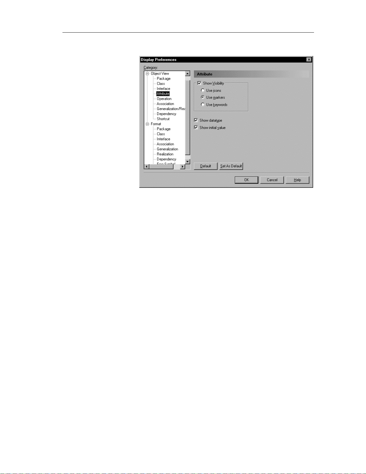
Chapter 2 Building an Object-Oriented Model
3 Select Attribute.
4 Modify the attribute display preferences.
5 Click OK.
61
Page 72

Defining identifiers
Defining identifiers
An identifier is a class attribute, or a combination of class attributes, whose
values uniquely identify each occurrence of the class. An identifier is the
OOM equivalent of a CDM identifier or a primary key or an alternate key in
a PDM.
Each class must have at least one identifier. If a class has only one identifier,
than it is designated by default as the primary identifier for the class. A
primary identifier is the main identifier for a class.
You can attach attributes or business rules to an identifier.
Identifier properties
An identifier has the following properties:
Property Description
Name Name of the identifier 254
Code Reference name for the identifier 254
Maximum
length
62
Comment Descriptive comment for the identifier —
Class Name of the class to which the identifier belongs to 254
Primary
identifier
Indicates that the identifier is the primary identifier of
the class. There can only be one primary identifier for
a given class
—
An identifier definition also includes the following properties, which are
defined on associated property sheets:
Property Description
Attribute Defines the characteristics of an identifier
Business rules A rule that your business follows. Business rules guide and
document the creation of a model
Page 73

Creating an identifier
You can create an identifier from a class.
v To create an identifier:
1 Double-click a class in the model.
2 Click the Identifier tab.
Chapter 2 Building an Object-Oriented Model
The class property sheet opens to the General page.
The Identifier page appears.
3 Click a blank line in the list.
or
Click the Add a Row tool.
An arrow appears at the beginning of the line.
4 Type a name and code for the identifier.
5 Click OK.
63
Page 74
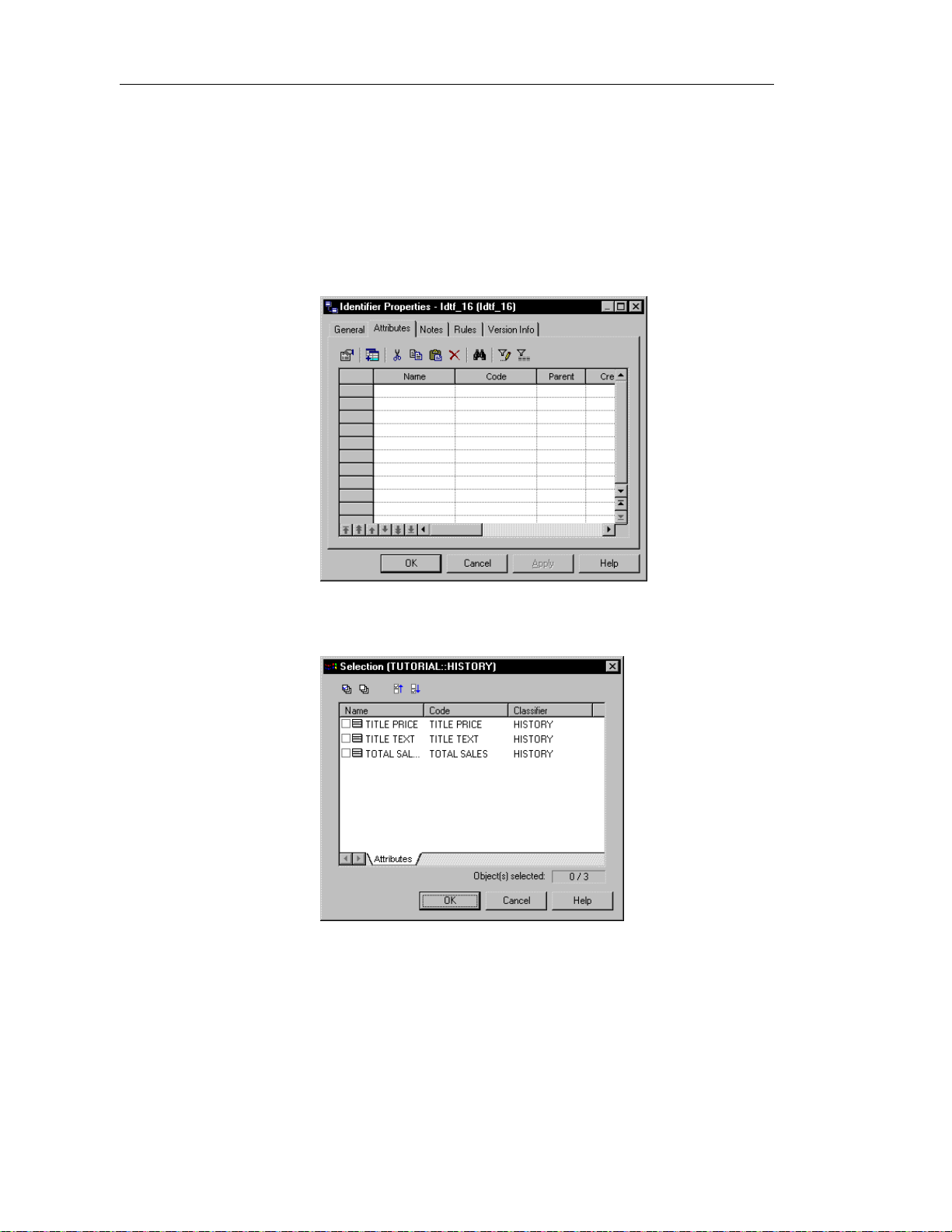
Defining identifiers
Adding attributes to an identifier
You can add attributes to an identifier.
v To add attributes to an identifier:
1 From the identifier property sheet, click the Attributes tab.
The Attributes page appears. It lists the attributes currently defined for
the identifier.
64
2 Click the Add Attributes tool.
A list of attributes defined for the class appears.
Page 75
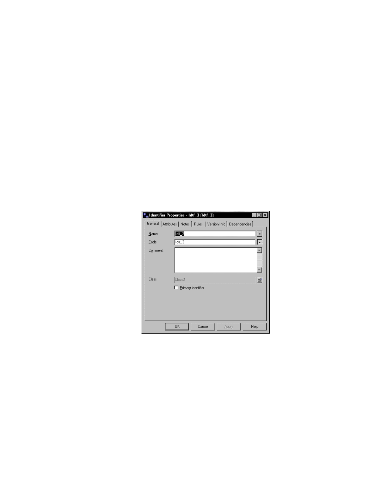
Chapter 2 Building an Object-Oriented Model
3 Select checkboxes for one or more class attributes that you want to
designate as an identifier.
4 Click OK in each of the dialog boxes.
Modifying identifier properties
There are two approaches to modifying identifier properties:
♦ Modify the property sheet of an identifier
♦ Modify an entry in the list of identifiers
Modifying identifier pr oper t i es f r om i t s pr oper t y sheet
The identifier property sheet displays the definition of the identifier, which
you can modify.
v To modify identifier properties from its property sheet:
1 Double-click the identifier in the model.
The identifier property sheet appears.
65
Page 76

Defining identifiers
Opening property sheets at last accessed page
Property sheets open to the General page by default. However, you
can choose to open property sheets at the last page accessed by
selecting Tools➤Options➤Dialog, and selecting the option Keep
Last Tab in the Property Sheets groupbox.
2 Type or select identifier properties as required.
3 Click OK.
Modifying identifier properties from the list of identifiers
The list of identifiers includes all identifiers attached to the current model.
You can modify the identifier properties from the list.
v To modify identifier properties from the list of identifiers:
1 Select Model➤Identifiers.
The list of Identifiers appears.
66
2 Click the identifier that you want to modify.
An arrow appears at the beginning of the line.
3 Modify any of the properties of the identifier directly in the list.
4 Click OK.
Page 77

Defining operations
An operation is a service that can be requested from an object to effect
behavior. It has a name and a list of parameters. An operation is a
specification of a transformation or query that an object may be called to
execute.
Operation names within a class must be unique. You can give identical names
to two or more operations only if they exist in different classes.
Operation properties
An operation has the following properties:
Property Description
Parent Object to which the operation belongs to 254
Name Name of the operation 254
Code Reference name for the operation 254
Comment Descriptive comment for the operation —
Chapter 2 Building an Object-Oriented Model
Maximum
length
Stereotype Subclassification of an operation derived from an
existing one. Extends the semantics of an operation
without changing it's structure
Return Type A list of values returned by a call of the operation.
If there are no values returned by the operation, the
return type value is null
Visibility Visibility of the operation, whose value denotes
how it may be seen outside its enclosing name
space
Event Significant occurrence that has a location in time
and space. An event can trigger a state transition
Abstract Indicates that the operation cannot be instantiated
and therefore has no d irect instances
Final Indicates that the operation cannot be redefined —
Static Defines the operation as static, meaning it cannot
be modified
—
—
—
—
—
—
An operation definition also includes business rules, and parameters, which
are defined on associated property sheets.
67
Page 78

Defining operations
Analyzing operation properties
The following operation properties each have several default values from
which you can select from:
♦ Visibility
♦ Stereotype
Visibility
Property Visible
Private Only to the operation itself
Protected Only to the operation and its inherited objects
Package To all objects cont ained within the same package
Public To all objects
Stereotype
Stereotype Description
constructor Operation that creates and initializes an instance of a class
Creating an operation
There are three ways to create an operation:
♦ Create an operation symbol in the Browser
♦ Add a new operation to the list of operations
♦ Create an operation from a class in a diagram
Creating an operation from the Br owser
v To create an operation from the Browser:
1 Right-click the Operations category in the Browser.
2 Select New from the contextual menu.
The property sheet of the operation appears.
68
Page 79

Chapter 2 Building an Object-Oriented Model
3 Type an operation name and an operation code.
4 Click OK.
A new operation is created in the Operations category.
Creating an operation from the l ist of operations
v To create an operation by inserting it in the list:
1 Select Model➤Operations.
The list of operations appears.
Accessing the list of operations
The list of operations is accessible only from a diagram. If the current
diagram is of a package, the list contains all the operations that exist
in the package. If the current diagram is of the model, the list contains
all the operations that exist in the model.
2 Click a blank line in the list.
or
Click the Add a Row tool.
An arrow appears at the beginning of the line.
3 Type an operation name and an operation code.
4 Click the Stereotype column.
5 Select a stereotype from the Stereotype dropdown listbox.
or
Type a stereotype in the Stereotype column.
6 Click the Return Type column.
7 Select a return type from the Return Type dropdown listbox.
or
Type a return type in the Return Type column.
8 Click the Visibility column.
9 Select a value from the Visibility dropdown listbox.
10 Click OK.
The operation is created for the class.
69
Page 80
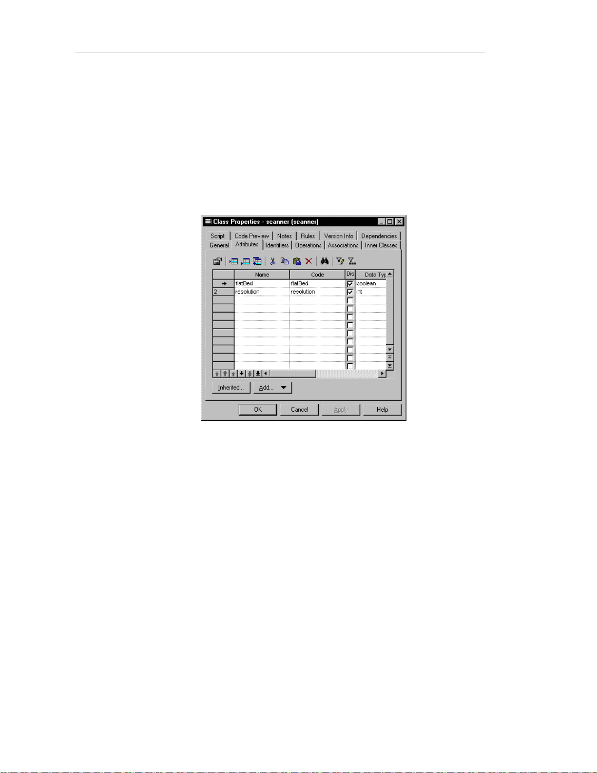
Defining operations
Creating an operation from a class in a diagram
You can create an operation from a class or an interface in a diagram in the
same way.
v To create an operation from a class in a diagram:
1 Double-click a class in the model.
The class property sheet appears.
2 Click the Operations tab.
The Operations page appears. It lists operations defined for the class.
70
3 Click a blank line in the list.
or
Click the Add a Row tool.
An arrow appears at the beginning of the line.
4 Type an operation name and an operation code.
5 Click OK.
The operation is created for the class and appears in the list of operations
for the class.
6 Click OK.
Page 81

Chapter 2 Building an Object-Oriented Model
Modifying operation properties
There are two approaches to modifying operation properties:
♦ Modify the property sheet of an operation
♦ Modify an entry in the list of operations
Modifying operation properti es f r om i t s pr oper t y sheet
The operation property sheet displays the definition of the operation that you
can modify.
v To modify operation properties from its property sheet:
1 Double-click a class in the model.
The class property sheet appears.
2 Click the Operations tab.
The Operations page appears. It lists operations associated with the
class.
3 Click the operation that you want to define.
An arrow appears at the beginning of the line.
4 Click the Properties tool.
or
Double-click the arrow at the beginning of the line.
71
Page 82

Defining operations
The operation property sheet opens to the General page.
Opening property sheets at last accessed page
Property sheets open to the General page by default. However, you
can choose to open property sheets at the last page accessed by
selecting Tools➤Options➤Dialog, and selecting the option Keep
Last Tab in the Property Sheets groupbox.
5 Type or select operation properties.
or
Click on a page tab.
Type or select operation properties as required.
6 Click OK.
Modifying operation properties from the list of operat i ons
The list of operations includes all operations attached to the current model.
You can modify the operation properties from the list.
v To modify operation properties from the list of operations:
1 Select Model➤Operations.
72
Page 83
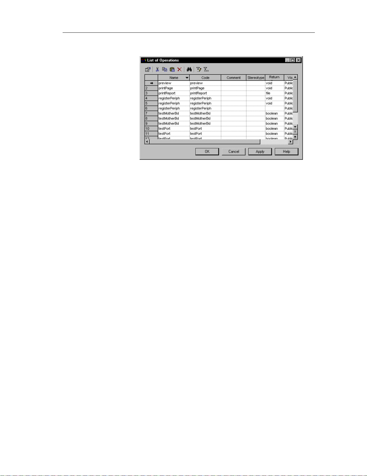
Chapter 2 Building an Object-Oriented Model
The list of operations appears.
2 Click the operation that you want to modify.
An arrow appears at the beginning of the line.
3 Modify any of the properties of the operation directly in the list.
4 Click OK.
Adding constructors and destructors to a class
A constructor is a special type of operation that creates and initializes an
instance of a class.
A destructor, on the other hand, is the complement of a constructor in that it
is an operation that it deinitializes and destroys the class instance. You can
only create a default destructor for a given class, and only if the current
object l anguage for the OOM is PowerBuilde r.
You can create constructors and destructors only from a class, from the
Operations page of the class property sheet.
Constructor and destructor names are assigned automatically by
PowerDesigner and you cannot modify them.
You cannot declare a Return Type for a constructor.
73
Page 84

Defining operations
You can create two types of constructor for a given class:
Default
Copy
A Default construc t or has no paramete rs.
Adding a Default constr uct or and dest ruct or t o a cl ass
You can define only one Default constructor and one Default destructor
(PowerBuilder only) for any given class.
If the current object language of the OOM is Analysis or Java, you can create
only one Default constructor and no Default destructor for a class. The
constructor has the same name as the class to which it belongs.
If the current object language of the OOM is Po werBuilder, you can create
one Default constructor and one Default destructor for a class. The
constructor has the name "constructor" and destructor has the name
"destructor".
v To add a Default constructor and destructor to a class:
1 Double-click a class in the model.
74
2 Click the Operations tab.
3 Click the Add button.
4 Select Default Constructor/Destructor from the dropdown list.
Page 85

Chapter 2 Building an Object-Oriented Model
If the current object langua ge of the OOM is Analysis o r Java, a Defaul t
constructor is created at the end of the list of operations for the class. It
has the same name as the class to which it belongs:
If the current object langua ge of the OOM is PowerBuilder, a Default
constructor and a Default destructor is created at the end of the list of
operations for the class. They have the names constructor and destructor:
75
Page 86
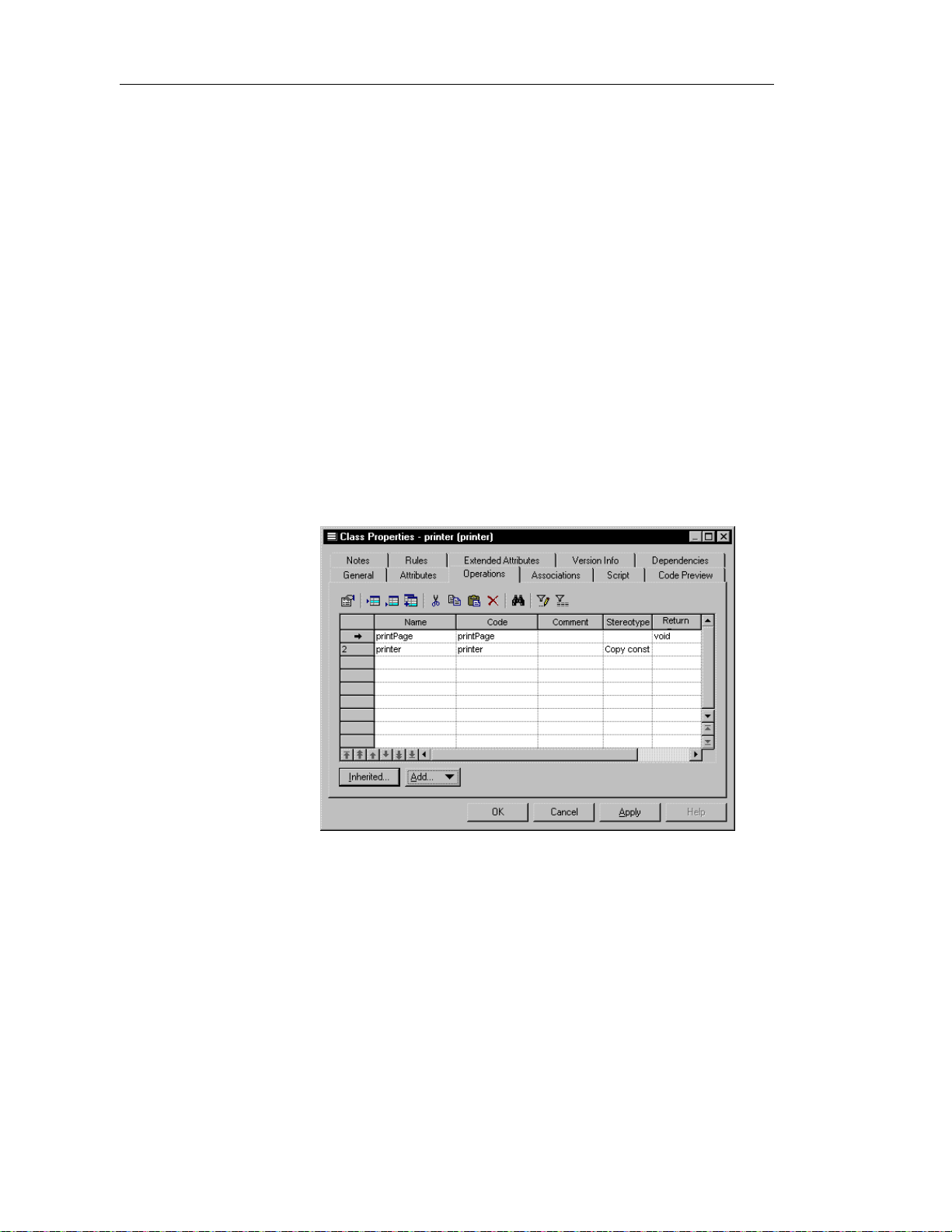
Defining operations
Adding a Copy const r uct or t o a cl ass
The body of a Copy constructor contains a copy of the attributes of the class
that exist at the moment of the creation of the constructor.
When you create a Copy constructor, it has the same as that of the class,
prefixed by the keyword new. It has a default parameter that you can modify,
or you can add other parameters.
If the class is an instance of another class, the attribute names within the body
of the Copy constructor operation are the same as those in the parent class.
You can define only one Copy constructor to any given class.
v To add a Copy constructor to a class:
1 Double-click a class in the model.
2 Click the Operations tab.
3 Click the Add button.
4 Select Copy Constructor from the dropdown list.
A Copy constructor is created at the end of the list of operations for the
class. It has the same name as the class to which it belongs.
76
Page 87

Adding operations to a class
You can add an operation to a class in one of the following two ways:
♦ Add a duplicate operation
♦ Add an operation from a parent class
Adding a duplicate operat ion to a class
A duplicate operation is an operation that creates and initializes an instance
of a class within the class.
When you create a duplicate operation, it has the name Duplicate, which you
can modify.
You can define only one duplicate operation to any given class.
v To add a duplicate operation to a class:
1 Double-click a class in the model.
2 Click the Operations tab.
3 Click the Add button.
Chapter 2 Building an Object-Oriented Model
4 Select Duplicate Operation from the dropdown list.
A duplicate operation, the name Duplicate, is created at the end of the
list of operations for the class.
77
Page 88

Defining operations
Adding an operation fr om a par ent cl ass
You can add to a class an operation that belongs to a parent class. The new
operation has the same signature (name and parameters) as the original
operation, but does not have its other properties.
Once you add an operation to a class in this way, you can modify only the
code implementation of the operation. You cannot modify the signature of
the operation.
v To add an inherited operation to a class:
1 Double-click a class that is linked to a parent class in the model.
2 Click the Operations tab.
3 Click the Inherited button.
The Inherited Operations window appears showing the operations that
belong to all the parent classes of the class.
78
4 Select an operation.
5 Click the Override button.
Page 89
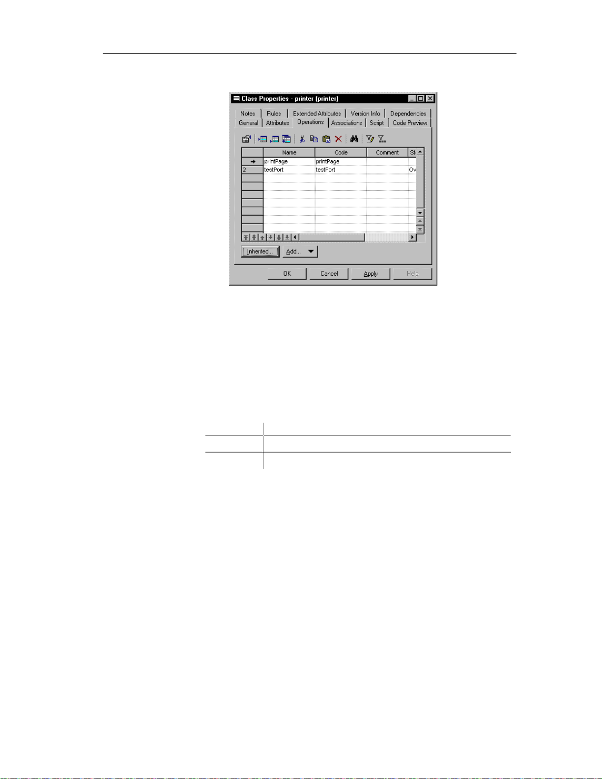
Chapter 2 Building an Object-Oriented Model
A copy of the operation is added to the list operations for the class.
Adding Getter and Setter operations to a class
Getter or a Setter operations are special types of operations that you create
for an attribute. You create a Getter or a Setter operation type from the list of
attributes of a class. For each attribute, you can create one Getter, one Setter
operation, or both a Getter and a Setter operation.
You create Getter or a Setter operations for sending a receiving data values
between fields.
Operation Description
Getter Returns a value from a field
Setter Puts a value into a field
v To add a Getter and a Setter operation to a class from an attribute:
1 Double-click a class in the model.
The class property sheet appears.
2 Click the Attributes tab.
The Attributes page appears.
3 Select one or more attributes.
79
Page 90
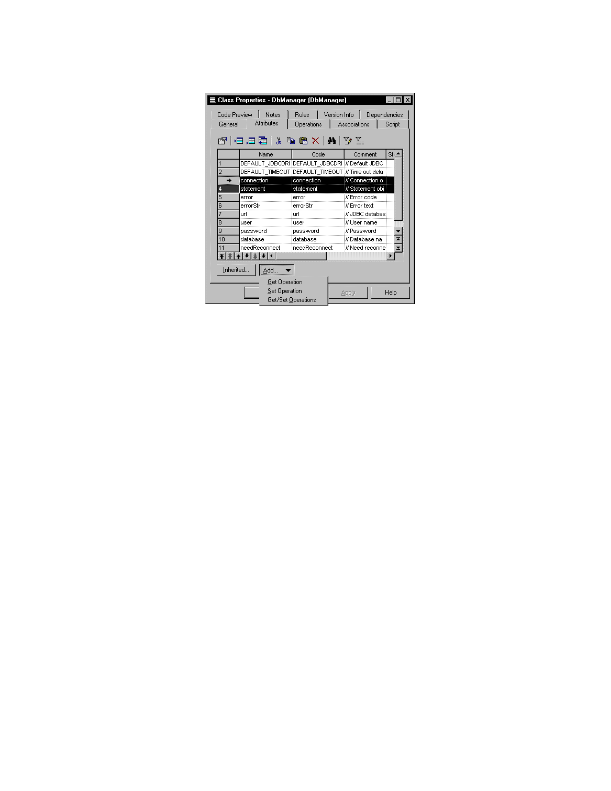
Defining operations
4 Click the Add button.
5 Select Get/Set Operations from the dropdown listbox.
80
The operations are created for the attributes. You can visualize them in
the list of operations of the class.
6 Select the Operations tab.
Page 91
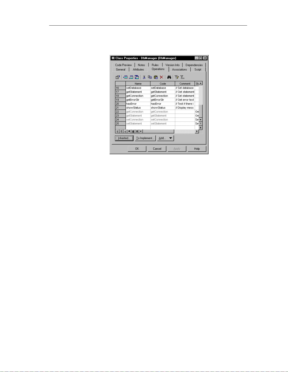
Chapter 2 Building an Object-Oriented Model
The newly created operations appear at the bottom of the list of
operations for the class. They are grayed indicating that their names can
not be modified.
7 Click OK.
Creating an implementation operation
When you create a realization link between a class and an interface in which
the class implements the interface, you create an operation in the class that
implements the interface.
81
Page 92

Defining operations
v To create an implementation operation:
1 Double-click a class that is linked to an interface by a realization link.
2 Click the Operations tab.
82
3 Click the To be implemented button.
The To Be Implemented Operations window appears. It contains a list of
all the operations of the interface that can be implemented from the class.
4 Select an operation from the list.
5 Click the Implement button.
A copy of the operation is created in the class.
Page 93
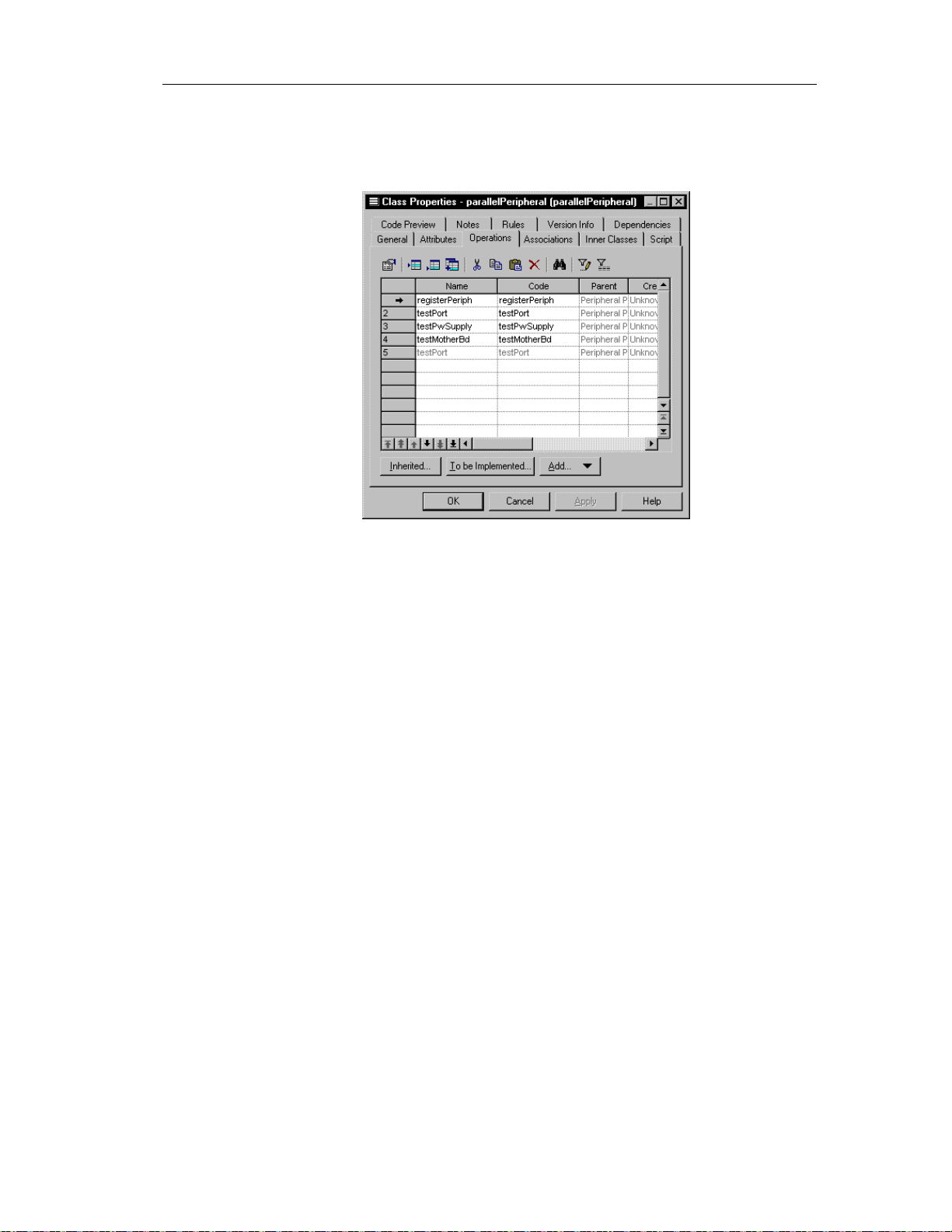
Chapter 2 Building an Object-Oriented Model
6 Click Close.
The newly created operation is added to the end of the list of operations
for the class. It is grayed, indicating that its name cannot be modified.
7 Click OK.
Modifying the code of an implementation operation
You can modify the code of an implementation operation from the
Implementation page of the operation property sheet.
$ For information on how to create an implementation operation, see the
section Creating an implementation operation.
v To modify the code of an implementation operation:
1 Double-click an implementation operation in the list of operations of a
class that implements an interface.
2 Click the Implementation tab.
83
Page 94
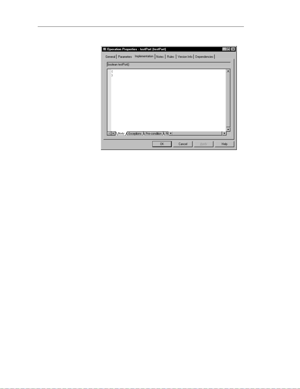
Defining operations
The Implementation page appears.
3 Type or modify code directly in the window.
or
Click a tab at the bottom of the edit window and type or modify code.
4 Click OK.
Copying an operation to another class
You can copy an operation from one class and add it to another class. If the
class already contains an operation with the same name or code as the copied
operation, the copied operation is renamed. For example the operation
testPort is renamed testPort2 when it is copied to a class which already
contains an operation testPort .
v To copy an operation to another class:
1 Double-click a class in the model.
The class property sheet appears.
2 Click the Operations tab.
The Operations page appears.
3 Click the Add Operations tool.
84
Page 95

Chapter 2 Building an Object-Oriented Model
A selection box appears. It lists operations attached to all other classes in
the model.
4 Select one or more operations in the list.
5 Click OK.
The copied operations appear in the list of operations for the current
class.
6 Click OK.
Displaying text in operation symbols
An operation has the following display preferences:
Preference Description
Show visibility Displays the operation as an icon, with markers, or using
keywords
Show return type When selected, displays the return type of the operation in
the operation symbol
Show parameters When selected, displays the parameters of the operation in
the operation symbol
85
Page 96

Defining operations
The visibility of an operation in a class or an interface can be displayed in
one of the following ways:
Visibility When selected
Icon Displays the operation as an icon
Markers Displays the visibility of the operation as a marker:
- (private), # (protected), + (public), or * (package)
Keywords Displays the visibility of the operation as a word:
private, protected, public, or package
You modify the display preferences for an operation in the Display
Preferences dialog box.
v To modify the display preferences:
1 Select Tools➤Display Preferences.
or
Right-click the diagram background and select Display Preferences from
the contextual menu.
The Display Preferences dialog box appears.
86
2 Expand the Object View node in the Category list.
3 Select Operation.
Page 97

Chapter 2 Building an Object-Oriented Model
4 Modify the operation display preferences.
5 Click OK.
87
Page 98
Defining parameters
Defining parameters
A parameter is a specification of a variable that can be changed, passed, or
returned. Parameters are used only for operations.
A parameter always has a direction, which indicates the flow of information.
Parameter properties
A parameter has the following properties:
Property Description
Parent Operation to which the parameter belongs to 254
Name Name of the parameter 254
Code Reference name for the parameter 254
Commen t Descriptive comment for the parameter —
Maximum
length
Direction
Data Type Set of instances that share the same operatio ns,
abstract attributes, and relationships, and semantics
Array Used in generating and r e ver s e engineering for Java
and PowerBuilder. When selected, arranges attributes
into table format
Parameter
Type
Direction of information flow of the parameter 254
—
—
The choice you make in the Direction dropdown listbox indicates what value
is returned when the parameter is called by the operation during the execution
process.
You can set the following values for the direction:
Value Description
In Input parameter passed by value. The final value may not be modified
and information is not available to the caller
In\Out Input parameter that may be modified. The final value may be modified
to communicate information to the caller
Out Output parameter. The final value may be modified to communicate
information to the caller
88
Page 99
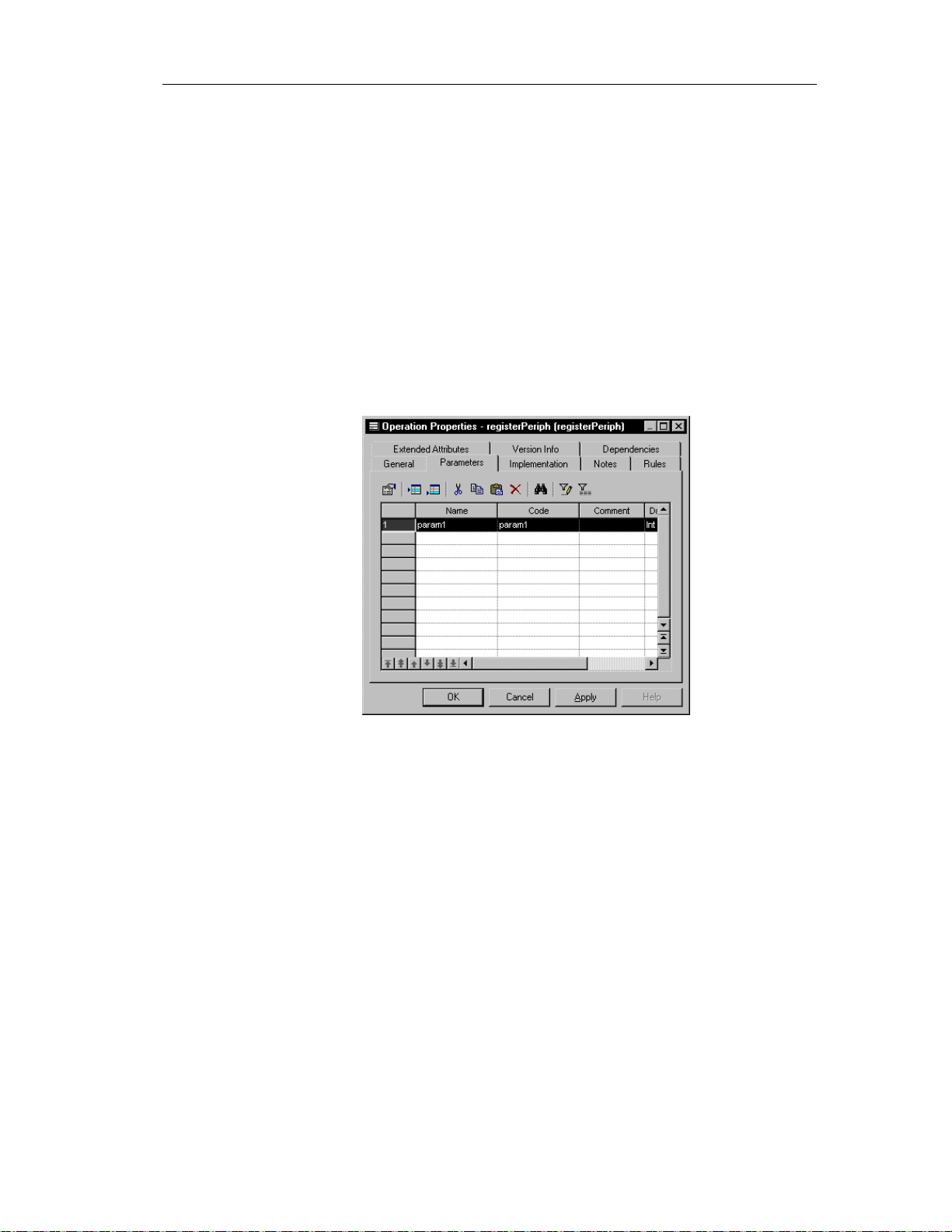
Creating a parameter
You can create parameters only from an operation. You create parameters
from the Parameters page in the operation property sheet.
v To create a parameter:
1 Double-click an operation in the model.
2 Click the Parameters tab.
3 Click the Add a Row tool
Chapter 2 Building an Object-Oriented Model
The Parameters page appears.
or
Click the first row.
A parameter is created.
4 Double-click the arrow at the beginning of the line.
A confirmation bo x appears asking you if you to confirm the creation of
the parameter.
5 Click OK
89
Page 100
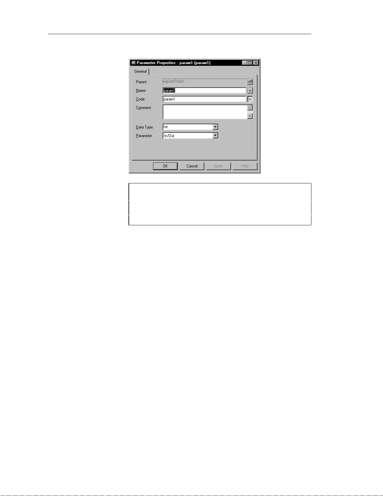
Defining parameters
The parameter property sheet opens to the General page.
Opening property sheets at last accessed page
Property sheets open to the General page by default. However, you
can choose to open property sheets at the last page accessed by
selecting Tools➤Options➤Dialog, and selecting the option Keep
Last Tab in the Property Sheets groupbox.
90
6 Type a name and code.
7 Select a value from the Direction dropdown listbox.
In/Out is the default direction value.
8 Click OK in all the open dialog boxes.
 Loading...