

Page 1

INSTALLATION AND OPERATION INSTRUCTIONS FOR
REVERSE OSMOSIS SYSTEMS
Basic™
Premium™
MetalsMaster™
BioMaster™
Other / Custom
Page 2

Table of Contents
A. Component Placement . . . . . . . . . . . . . . . . . . . . . . . . . . . . . . . . . . . . . . . . . . . . . .2
B. Component Information . . . . . . . . . . . . . . . . . . . . . . . . . . . . . . . . . . . . . . . . . . . . .2
C. Installation . . . . . . . . . . . . . . . . . . . . . . . . . . . . . . . . . . . . . . . . . . . . . . . . . . . . . . . . .4
D. Startup Procedures . . . . . . . . . . . . . . . . . . . . . . . . . . . . . . . . . . . . . . . . . . . . . . . . . .7
E. Maintenance . . . . . . . . . . . . . . . . . . . . . . . . . . . . . . . . . . . . . . . . . . . . . . . . . . . . . . .8
F. Flow Diagram . . . . . . . . . . . . . . . . . . . . . . . . . . . . . . . . . . . . . . . . . . . . . . . . . . . . . .10
G. Troubleshooting . . . . . . . . . . . . . . . . . . . . . . . . . . . . . . . . . . . . . . . . . . . . . . . . . . . .11
A. Component Placement
A.1 Faucet Placement
Proper faucet placement should ensure a no-splash waterfall pattern into the
sink. The faucet handle should normally be positioned to either the left or the
right of your existing faucet as one faces the sink.
A.2 Pressurized Storage Tank
In a typical installation, the closer to the faucet that the storage tank can be,
the better. If you locate the storage tank under the sink it should be placed so
that it can be easily removed from under the sink. Avoid placing the storage
tank in an out-of-the-way location. There are two reasons for this: First, the
difficulty of installation increases significantly; Second,when the storage tank is
located further away from the faucet, the flow rate decreases.
A.3 RO System Assembly Placement
The reverse osmosis system assembly bracket should be hung on a wall or sink
cabinet side wall with the two screws provided. Be sure to either:
3.1 Leave enough length of both blue and orange tubing so the system
assembly can be lifted off the mounting screws and removed from under
the sink for periodic cartridge replacement , or...
3.2 Leave enough bottom clearance to remove and replace the cartridges
from their respective housings after the housings have been unscrewed for
servicing.
A.4 Pressurized Storage Tank Placement
The storage tank can be placed anywhere within the vicinity of the reverse
osmosis system. It can be placed vertically or horizontally. It is suggested for
proper flow rate not to exceed placement more than 5 feet away from the
reverse osmosis system. If a distance of more than 5 feet from the reverse
osmosis system is required, larger tubing may need to be installed between the
storage tank and the reverse osmosis system.
B. Component Information
B.1 Filter Cartridges
Sediment Cartridges
Sediment cartridges are designed to remove large amounts of suspended
particals from water to help reduce the probability of clogging the reverse
osmosis membr
ane.
2
Page 3

Carbon Cartridges (Basic and Premium Series)
Carbon cartridges remove taste and odor, chlorine, pesticides, and other
contaminants from the water. These are a necessity on chlorinated water as a
pretreatment for systems with thin film membranes (TFM), because the chlorine
will greatly reduce the life of this type of membrane. They also help prevent
fouling on the quartz sleeves in systems with ultraviolet sterilizers.
Special Metals Reduction Cartridge (MetalsMaster and BioMaster Series only)
B.2 Reverse Osmosis Membranes
The reverse osmosis membrane is made from a semi-permeable material. Its
function is to separate water molecules from dissolved impurities in the water.
This is accomplished by the application of pressure greater than the osmotic
pressure in water containing dissolved solids.
There are two main types of reverse osmosis membranes. The first type (used in
Basic Series) is made of cellulose acetate (CA).These have a higher resistance
to chlorine, but should not be used on water supplies that have bacteriological
contamination. The second type (used in Premium, MetalsMaster, and
BioMaster Series) are made of a thin film composite material (TFM).These have
a poor resistance to chlorine, but will not be destroyed by bacteriological
contamination. These usually also have higher flow rates available.
B.3 Ultraviolet Sterilizers
The ultraviolet light used for sterilizing is at a specific wavelength (254 nm) that
destroys or inactivates the DNA of micro-organisms to render them harmless.
Important Safeguards:
• Never look directly at an unshielded UV lamp.
It can cause permanent
eye damage. Always wear protective eye wear such as eye glasses or
safety glasses.
• Great caution should be exercised when handling a lamp to avoid burns.
UV lamps run extremely hot.
• To prevent electrical shock, never immerse or wash the unit in water while
the bulb is inside or when the unit is plugged in.
• ALWAYS DISCONNECT THE UNIT FROM THE ELECTRICAL POWER SOURCE
before replacing the UV bulb or servicing any part of the unit.
• Never operate the unit if it has malfunctioned, has a damaged cord or
plug, or has been dropped or damaged in any manner.
• Use only those attachments recommended by the manufacturer.
• The Polisher Biolyte™ sterilizer should not be used for any purposes other
than its intended function. This unit is designed to treat possible bacteria
contamination at the rated specifications and operating limits listed
below:
Water Pressure . . . . . . . . . . . . . . . . . . . . . . . 100 psi
Capacity @ 10 mic. Clear Water . . . . . . . . 0.7 gpm (3 liters)
Lamp Life. . . . . . . . . . . . . . . . . . . . . . . . . . . . 9,000 hours (12 months)
Output . . . . . . . . . . . . . . . . . . . . . . . . . . . . . . 30,000 microwatt seconds/cm²
WARNING: This filter must be protected from freezing.Failure to do so may result
in cracking of the filter and water leakage. UV is for bacteria and virus control
only
. UV does not kill giardia, cryptosporidium, or other cysts. Make certain that
the installation complies with all state and local laws and regulations.
3
Page 4

C. Installation
C.1 Drilling the Faucet Hole (Only if a sink hole is not already provided):
Once the location of the faucet has been determined, always check below
the point you are about to drill to ensure it is unobstructed where the hole will
exit, and that it isn't over a reinforcing rib.
1.1 Center punch the desired location to provide a starting point for your drill.
1.2 Drill a 1/8” pilot hole.
1.3 Enlarge the pilot hole with a 1/2” drill (or 1¼”high speed steel hole saw for
an air gap faucet).
1.4 Remove all burrs and sharp edges.
1.5 Immediately clean up sink area.
Note: If an enamel or porcelain sink is encountered, it is very important that a
layer of porcelain be removed before following the steps outlined above. This
can be accomplished by gently grinding away, using a hobby grinder and a
silicon carbide wheel, enough area of porcelain down to the metal base to
accommodate the hole size needed. The drill or hole saw must not contact
surrounding porcelain or chipping can occur.
C.2 Standard Faucet Installation
2.1 Slide the faceplate and black rubber gasket on to the faucet stud.
2.2 Place the stud through the hole from the top of the sink or countertop.
Properly position the faucet, handle, and faceplate with gasket.
2.3 From under the counter, slide on the black locating washer, used where a
1/2” hole is available or reverse when mounting on stainless steel or when
using drilled hole.
2.4 Slide on the washer and nut.
2.5 Be sure faucet spout and body are in proper position, and tighten nut,
while holding the faucet in position with a padded crescent wrench. Be
careful not to over tighten.
C.3 Air Gap Faucet Installation (optional on some equipment)
The air gap faucet includes an anti-siphon device as required by regulatory
agencies in some states. The purpose of the air gap is to prevent water in the
drain from backing up into the RO drinking
water system.It is a dry air gap and allows 1”free
fall above the clear line which satisfies all known
agencies.
3.1 Slide the face plate and rubber gasket on
to the stud.
3.2 Place the stud through the drilled hole.
Properly position the faucet, handle, and
face plate with gasket.
3.3 From under the counter, slide on the steel
slotted washer, white plastic spacer (open
end upw
ar
ds),
washer, and nut.
4
1/4” Black Tube
(reject water from
RO system)
3/8” Black Tube
(to drain)
1/4” Blue Tube
(product water
from RO system)
Page 5

Be sure faucet spout and body are in position,and align the slotted washer and
spacer to allow access to hose barbs. Tighten the hex nut while holding the
faucet in position with a padded crescent wrench.Do not over tighten.
C.4 Angle Stop Valve Installation
4.1 Turn off cold water supply.
4.2 Disconnect riser hose from cold water supply valve.
4.3 Ensure that sealing gasket is fully seated into angle stop valve female thread.
Install angle stop valve (female thread side) on cold water supply valve.
4.4 Connect riser hose to angle stop valve on male thread side.
DO
NOT open the angle stop valve or cold water supply valve at this time.
C.5 Drain Saddle Assembly Installation
The RO system comes supplied with a drain saddle and mounting hardware
which fits around a standard 1½” O.D. drain pipe.
5.1 The drain saddle should be installed above the trap, on the vertical or
horizontal tailpiece. It should never be placed close to the outlet of a
garbage disposal.
5.2 Drill a 5/16” hole in the drain pipe in the location where the drain saddle
will be positioned. Support the drain against drilling pressure. Do not drill
through both sides of the drain pipe.If possible, place the hole so the drain
saddle fitting will angle toward the faucet location.
5.3 Position the drain saddle so that the drain fitting is over the hole in the drain
pipe.
5.4 Tighten the drain saddle screws evenly and firmly so a good seal is made.
Avoid over tightening.
Note: Some state or local codes may require that the drain saddle be served
by a trap other than the one serving the garbage disposal. Before making a
connection, please check your code regulations.
C.6 Pressurized Storage Tank Valve Installation
6.1 Remove the protective plastic cap from the 1/4” NPT fitting on the top of
the storage tank.
6.2 Wrap the 1/4” NPT fitting with Teflon tape (plumbers tape).
6.3 Thread the storage tank valve onto the 1/4”NPT fitting.Avoid over tightening.
C.7 Filter Cartridge Installation
7.1 Unscrew the filter housing sumps by hand or with a spanner wrench.
7.2 Rinse out each of the housings and fill about 1/3 full with water. Add about
2 to 3 tablespoons of bleach and scrub thoroughly with a brush or sponge.
Rinse thoroughly.
7.3 Install the cartridge into the sump making sure that it slips down over the
sump standpipe.
7.4 Turn the sump into the cap and hand tighten. Do not over tighten.
5
Page 6
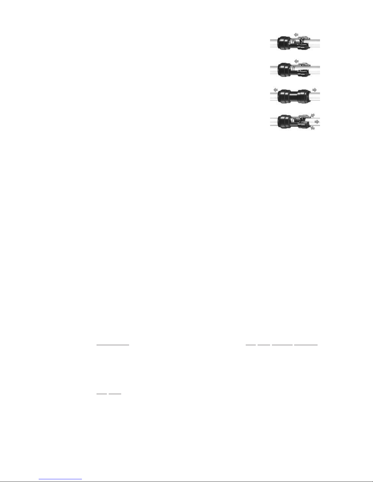
C.8 Using Quick Connect Fittings
8.1 Insert tube through collet of fitting. The fitting will be
gripped before it will seal.
8.2 Push the tube all the way into the fitting to the stop.The
collet has stainless steel teeth which grip the tube while
the o-ring provides a permanent leakproof seal.
8.3 Pull the tube to check that it is secure.It is good practice
to check the system before it is used.
8.4 To disconnect, ensure that the system is depressurized.
Push the collet against the face of the fitting. With the
collet held in this position, pull on the tube to remove it.
C.9 Reverse Osmosis Membrane Installation
9.1 Disconnect the processed water line from the RO housing end cap via the
quick connect fitting.
9.2 Twist off the end cap from the housing.
9.3 Apply a fresh coating of a FDA approved silicone lubricant to the two
o-rings on the end of the membrane.
9.4 Insert the membrane into the housing with the “two o-ring end” first.
9.5 Thread the cap back on and hand tighten firmly.
9.6 Reconnect the processed water line by inserting it into the quick connect
fitting.
C.10 Ultraviolet Lamp Installation
(Systems with the Polisher Biolyte™ Ultraviolet Sanitizer Only)
10.1 Unscrew white cap with silicon plug from stainless steel UV chamber.
10.2 Carefully insert bulb into the quartz sleeve. Be sure the wire is hanging out
of the quartz sleeve.
10.3 Push the stopper (which is attached to the wire) into the quartz sleeve.
10.4 Remove the silicon plug from the white cap.
10.5 Slide the wire through the hole in the cap.
10.6 C
AREFULLY screw the cap onto the UV chamber. DO NOT CROSS THREAD.
There is a glow bottle starter attached to the lamp. This should be left
inside of the cap.
10.7 Replace the silicon plug around the wire into the cap.
10.8 Plug the wire into the power adapter.
10.9 DO
NOT attach the power adapter to a power source at this time.
C.11 Connecting Components
Most connections are with plastic quick connect type fittings (see C.8 above).
The exception is the dr
ain saddle w
hich has a compr
ession type fitting that uses
a nut and a plastic insert. Systems with air gap faucets have two slip-on barbed
tubing connections.
6
Page 7

11.1 Connect the orange tube (feed water) to the angle stop valve on the
cold water supply line.
11.2 Connect the blue tube (product water) from the RO system assembly to
the quick disconnect fitting on the faucet.
11.3 Connect the yellow tube (processed water) to the storage tank valve
fitting.
11.4 Connect the black tube (reject water) to the drain saddle fitting.If you are
using a system with an air gap faucet: connect the 1/4”black tube to the
1/4” barb on the faucet and the 3/8” black tube from the faucet to the
drain saddle fitting. The 3/8” black tube should not have any loops or
should not drop below the drain saddle connection. Shorten the 3/8”
tubing if required.
Note: Make sure there are no kinks in any of the tubing.
D. Startup Procedures
1. Turn on the cold water line valve and check for leaks. Correct any problems if
necessary.
2. Purge the air out of the system by slowly opening the angle stop valve on the
cold water supply line. Be sure the storage tank valve is open.When open, the
valve handle should be parallel with the tubing.
3. Open the faucet.The water should begin to trickle within a few minutes.The RO
system should now be processing water.
4. Close the faucet when water begins to trickle, and DO
NOT open the faucet
again for at least 2 to 3 hours. It will take approximately 2 to 3 hours for the
holding tank to fill.
5. After 2 to 3 hours, open the faucet and completely drain the storage tank.You
should expect air and carbon fines (black powder) from the carbon filter. This is
normal and not hazardous.
6. It is important that the system be flushed at least once. If there is still a slight foul
taste in the water or carbon fines after flushing the system once, repeat steps 4
and 5.
Note: It will not be uncommon to experience air bubbles or effervescence in the
product water. This will disappear after the system is in service for a short period of
time.
WARNING: This reverse osmosis membrane contains a preservative to prevent
microbiological growth and freezing, which, if ingested, may cause irritation of the
gastrointestinal tract, colic, diarrhea, or other similar symptoms. Therefore, 2 to 5
gallons (approximately 1 to 2 full tanks) must be drawn from the faucet to flush out
the preservative before the unit should be considered operational. If there is still a
slight foul taste to the water,run another 2 to 3 gallons of water through the faucet.
7
Page 8

E. Maintenance
E.1 Filter Cartridges
Sediment and carbon filters have different effective lives when used on
different water systems. The amount of use that the cartridge receives also
determines its life. A family of two usually will not use as much filtered water as
a family of six.No amount of water metering or maintenance scheduling will be
an absolute guarantee of performance. Common sense, and the help of your
local water treatment professional is still the best way to maintain a properly
functioning filtration system. New cartridges (and changing cartridges often)
will enhance performance.
A sediment filter’s function is to remove suspended particles from the water,
thus reducing the possibility of clogging the reverse osmosis membrane. The
flow rate will slow down as the cartridge becomes clogged. When the water
flow slows down perceptively, it’s time to change the cartridge. Depending on
your water supply, this could be as soon as 2 months, or as long as 1 year. We
recommend at least an annual change.
Carbon cartridges remove taste and odor, chlorine, pesticides, and other
contaminants from water. Special advanced-style carbon blocks also remove
metals such as lead, iron, and copper. They also prevent iron fouling of the
quartz sleeves in UV equipped systems. The carbon cartridges should be
changed at a minimum every 12 months (or earlier if you notice any change in
the taste or smell of your water). Again, your local water professional will be
familiar with the quality of your water supply and can offer valuable advice
and/or periodic testing, depending on the quality of your feed water.
Replacing Filter Cartridges
1.1 Turn off the feed water supply to the RO system assembly. Open the
RO faucet and let it bleed all the water from the RO holding tank.
1.2 Turn the storage tank valve to the closed position.(90 degree angle to
the water line.)
1.3 Unscrew the filter housing sumps by hand or with a spanner wrench.
1.4 Remove the used cartridge and discard. Rinse out each of the
housings and fill about 1/3 full with water. Add 2 to 3 tablespoons of
bleach and scrub thoroughly with a brush or sponge. Rinse thoroughly.
1.5 Remove the o-ring from the housing and wipe the groove and o-ring
clean. Lubricate the o-ring with a coating of clean petroleum jelly.
Place the o-ring back into the groove. If the o-ring appears damaged
or crimped, it should be replaced immediately.
1.6 Install the new cartridge into the sump making sure that it slips down
over the sump standpipe.
1.7 Turn the sump into the cap and hand tighten. DO
NOT OVER TIGHTEN.
If the membrane needs to be changed, go to
Replacing the RO Membrane
1.8
Slo
wly tur
n on the f
eed (incoming) water supply and allow the housings
to fill with water. Check for any leaks.
1.9
T
ur
n the storage tank valve to the open position (parallel with the
water line).
8
Page 9

E.2 Reverse Osmosis Membrane
RO membranes remove dissolved (not visible) contamination from water (all
the way down to the molecular level). The membrane in your system may last
for several years in the proper application.The most obvious indication that your
membrane needs to be changed is a slow down in the manufacturing of water
(i.e. your storage tank does not refill as quickly with water as it once did). If your
RO system contains a pressure gauge the membrane should be changed
when a 15 psi drop is determined.Your water can also be periodically checked
to determine its TDS level.
Replacing the Reverse Osmosis Membrane
2.1 Turn off the feed waterline. Open the RO faucet and drain the water
from the tank.
2.2 Disconnect the processed water line from the RO housing end cap
via the quick connect fitting.
2.3 Twist off the end cap from the housing. (Reasonable force may have
to be used if the end cap has been on for several years).
2.4 Remove and discard the old membrane.
2.5 Apply a fresh coating of a FDA approved silicone lubricant to the two
o-rings on the end of the membrane.
2.6 Insert the membrane into the housing with the ‘two o-ring end’ first.
2.7 Apply a fresh coating of a FDA approved silicone lubricant to the
o-rings on the membrane housing.
2.8 Thread the cap back on and hand tighten firmly.
2.9 Reconnect the processed water line by inserting it into the quick
connect fitting.
2.10 Slowly turn on the feed water while checking for any leaks.
WARNING: This reverse osmosis membrane contains a preservative solution
to prevent microbiological growth and freezing, which, if ingested, may
cause irritation of the gastrointestinal tract, colic, diarrhea, or other similar
symptoms.Therefore,2 to 5 gallons (approximately 1 to 2 full tanks) must be
drawn from the faucet to flush out the preservative before the unit should
be considered operational.If there is still a slight foul taste to the water, run
another 2 to 3 gallons of water through the faucet.
NOTE: Manufacturer recommends that the flow capillary be changed
every time the membrane is replaced. Disconnect the black reject water
tubing from the RO housing drain port. Remove the flow capillary from the
tubing and replace it with a new one. IMPORTANT: Be sure to match the
size of the new flow capillary to the new membrane.
E.3 Ultraviolet Lamp
(Systems with the Polisher Biolyte™ Ultraviolet Sanitizer Only)
Change the ultraviolet lamp annually. The ultraviolet lamp in your filtration
system emits a very powerful and specific UV wave length for the sterilization of
micr
oor
g
anisms. This wave length is not visible to the naked eye. It is very
important that the lamp be changed once every year even if the lamp is still lit.
Visible light is not an indication of UV output. After one year, a UV lamp
degrades very quickly until it is no longer effective, even if the lamp is still lit.
9
Page 10

Replacing the Ultraviolet Lamp
3.1 Unplug the power adapter from the electrical outlet.
3.2 Unplug the lamp from the power cord.
3.3 Loosen and remove the white silicone plug from the white end cap.
3.4 Unscrew the white end cap with the silicone plug.
3.5 CAUTION: The old lamp could be very hot. Do not handle until lamp
has cooled down sufficiently.
3.6 Slide the old lamp out of the quartz sleeve and discard the lamp and
the silicone plug.
3.7 Carefully insert bulb into the quartz sleeve. Be sure the wire is hanging
out of the quartz sleeve.
3.8 Push in stopper (cap) which is attached to the wire into the quartz
sleeve.
3.9 Remove silicon plug from cap.
3.10 Slide the wire through the hole in the cap.
3.11 Carefully screw the cap onto the UV chamber. DO
NOT CROSS
THREAD. There is a glow bottle starter attached to the lamp. This can
be left inside of the cap.
3.12 Replace the silicon plug around the wire into the cap.
3.13 Plug the wire into the power adapter.
3.14 Plug the adapter into the correct power supply. (The use of a ground
fault protected outlet is recommended).
F. Flow Diagram
10
Pressurized
Storage
Tank
Sediment Prefilter
(Basic,
MetalsMaster,
BioMaster Only)
Carbon Block Prefilter
(Pr
emium, MetalsMaster,
BioMaster Only)
Carbon Bloc
k Postfilter
Polisher™ Ultraviolet Sterilizer
(BioMaster Only)
Reverse Osmosis Membrane
A
uto
Shut-off
V
alve
To Tank
(Yellow)
To Faucet
(Blue)
Feed Water
(Orange)
IN
OUT
To Drain
(Black)
T
ANK
Page 11

G. Troubleshooting
Problem Possible Cause Solution
1. No product water/ a. Feed water supply turned off. a. Turn on feed water supply.
not enough product water. b. Feed water pressure too low. b. Feed water pressure must be at least 35psi.
c. Feed water tubing kinked or plugged. c. Remove blockage or kink in line.
d. Flow/pressure control plugged. d. Flush out flow control; replace if necessary.
e. Product water check valve plugged. e. Clean or replace check valve.
f. Membrane fouled/clogged. f. Replace membrane element.
g. Storage tank is over pressurized. g. Drain tank, and relieve air to 10 psi.
h. System has been used too much. h. Convert system to higher production output.
i. Storage tank valve turned off. i. Open tank valve.
j. Prefilter(s) fouled or clogged. j. Replace prefilter(s).
2. Low flow rate from faucet. a. Low precharge in storage tank. a. Increase air pressure to 7 to 10 psi in tank
with product water drained.
b. Storage tank diaphragm ruptured. b. Replace storage tank.
c. Tank valve partially closed. c. Completely open tank valve.
3. High TDS product water. a. Check-valve failure on flow control. a. Replace check-valve tee.
b. Membrane fouled, hydrolyzed, ruptured b. Replace membrane.
or attacked by bacteria.
c. TDS increased in feedwater. c. Contact dealer for revised product water TDS.
d. Filters weren’t flushed properly. d. Flush system again.
4. Bad tasting or smelling a. Increase in product water TDS. a. See High TDS Product Water above.
product water. b. Post-filter exhausted. b. Replace post-filter.
c. Storage tank and system contaminated. c. Replace sediment and carbon filters. Sanitize
tank and system.
d. Product line and waste line connections d. Check lines and make corrections.
are reversed.
e. Membrane life expired. e. Replace membrane and flush system.
f. UV bulb burned out. f. Replace UV bulb.
5. Cloudy water. a. Dissolved oxygen in feedwater, which a. Usually clears up as condition of feedwater
is concentrated in product water. changes. Letting water stand will allow
dissolved air to dissipate.
(CONTINUED ON NEXT PAGE)
11
Page 12

G. Troubleshooting (Continued)
Problem Possible Cause Solution
6. Cloudy ice cubes. a. TDS increased in product water. a. See High TDS Product Water above.
b. Dissolved oxygen in feedwater, which b. See Cloudy Water above.
is concentrated in product water.
c. Larger (square shaped) ice cubes are c. Change ice cube shape. Let water stand to
usually clearest; small, round ice cubes release dissolved oxygen before freezing.
are usually cloudier.
7. Faucet leaks. a. Leak through spout. Valve tee bar is a. Raise tee bar so there is just a little play in
set too low or valve seat is defective. handle in the off position,or replace valve
assembly.
b. Leak around stem. O-ring seals worn b. Replace valve assembly.
on valve assembly.
8. Overflow at faucet air gap. a. Drain tubing kinked or plugged. a. Straighten and clean/flush drain tubing.
b. Tubing connections are reversed. b. Check tubing connections and correct.
c. Air gap plugged. c. Clean with vinegar and/or soap.
d. Drain tubing not in downward sloped d. Check for low spots and loops.
position.
e. Pipe tap (drain saddle) not aligned e. Realign pipe tap (drain saddle).
properly.
9. No blue glow emitting from a. Lamp burnt out. a. Replace lamp.
UV chamber site ports. b. Power adapter not plugged into wall outlet. b. Plug into wall.
c. Lamp not plugged in properly to PIN c. Check connections and adjust.
connector.
d. Ballast is burnt out. d. Replace ballast.
12
03/11
 Loading...