

SWR Sound SM-1500 User Manual
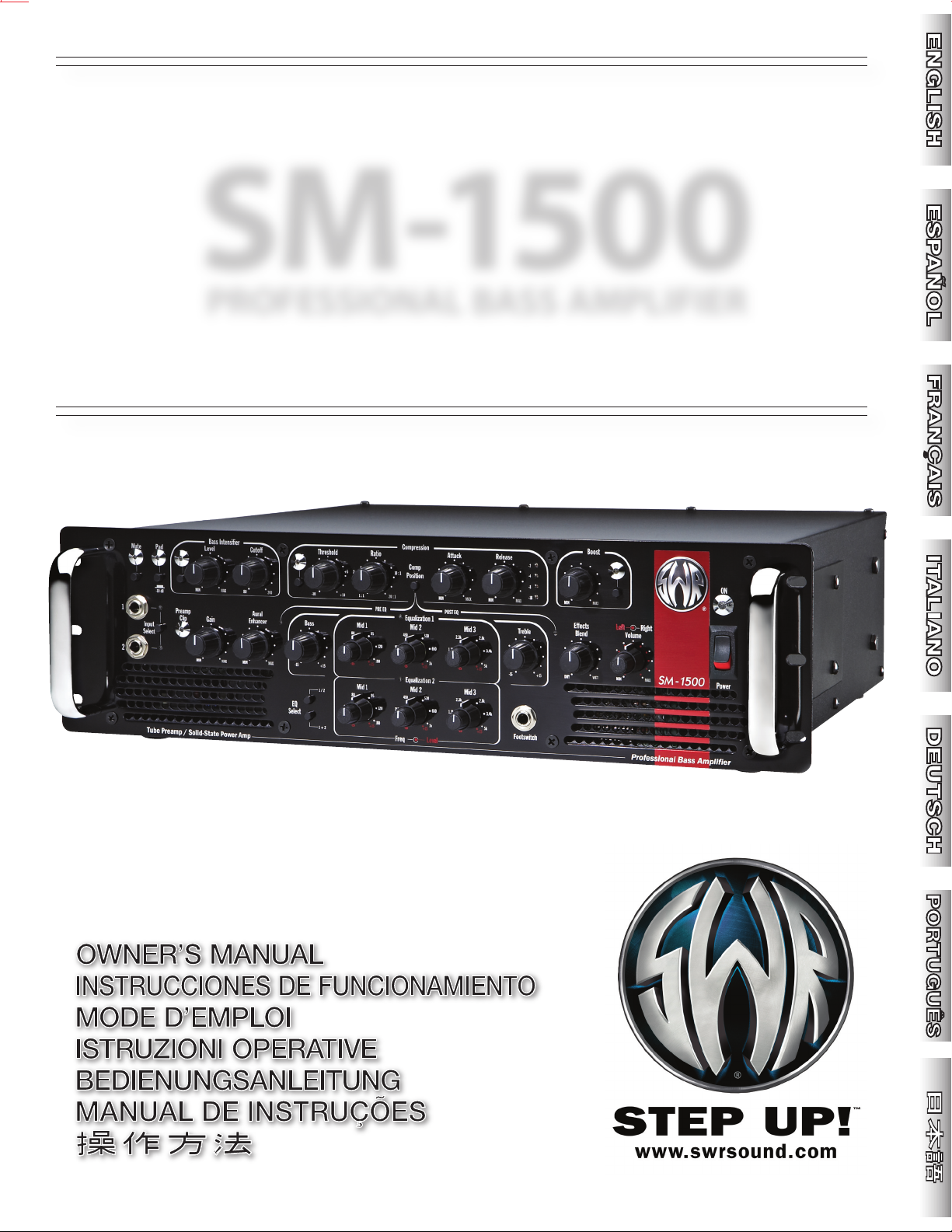
SM-1500
PROFESSIONAL BASS AMPLIFIER
ENGLISH - PAGES . . . . . . . . . . . 6–13
ESPAÑOL - PAGINAS . . . . . . . 14–21
FRANÇAIS - PAGES . . . . . . . . . . 22–29
I m p o r t a n t S a f e t y I n s t r u c t i o n s
Th is symb ol warns the user of d angerou s voltag e levels locali zed with in
the enclos ure.
Th is symbo l advi ses the use r to read all ac company ing liter ature for
safe operation of t he unit.
∆ Read, retai n, and follo w all instruct ions. Heed all wa rnings.
∆ Only c onnect the po wer s upply cord t o an ea rth grounde d AC recepta cle i n
acco rdance with the volta ge an d freq uency rating s lis ted un der I NPUT POWER on
the rea r pane l of this product.
∆ WARNING: To p revent damag e, fi re or s hock hazard, d o not expose this u nit t o
rain or m oisture .
∆ Unplug the po wer sup ply cord be fore clean ing th e unit exter ior (use a damp cloth
only ). Wait until the u nit is compl etely dry b efore reconnecti ng it to power.
∆ Maintain at least 6 i nches (15. 25 cm) of uno bstruc ted ai r space behin d the u nit to
allow for proper ven tilatio n and cooli ng of the u nit.
∆ This p roduct sh ould be lo cated away f rom heat sources s uch as radiator s, heat
register s, or other produc ts that p roduce heat.
ITALIANO - PAGINE . . . . . . . . 30–37
DEUTSCH - SEITEN . . . . . . . . . . 38–45
PORTUGUÊS - PAGINA. . . . . . . 46–53
∆ This product may be equipp ed with a polarized plug (on e blade wi der than the
other). This is a s afety feature. If yo u are u nable to inser t the plug i nto the outle t,
cont act an electric ian to replace yo ur obsolete outl et. Do not defe at the safet y
purp ose o f this plug.
∆ Prote ct th e power s upply cord fro m bei ng pin ched or abraded.
∆ This produ ct shoul d onl y be used with a cart, stan d or rack that is re commended
by the ma nufacturer.
∆ The power s upply cord of this product shoul d be unpl ugged from th e outl et whe n
left u nused for a lo ng per iod of t ime, o r duri ng ele ctrica l stor ms.
∆ This prod uct should be ser viced by quali fied serv ice pers onnel when : th e po wer
supply cord or the plug has been damage d; or objec ts have fallen , or liquid has
been spill ed onto the pro duct; or th e p roduct has been ex posed to rai n; or the
product does not a ppear to op erate no rmally or e xhibits a m arked c hange i n
per forman ce; or the product h as bee n drop ped, or t he enc losure damaged.
∆ Do not d rip no r splash liquids, nor place liqui d filled contai ners o n the un it.
∆ CAUTION : No user servi ceable parts inside , refer ser vicin g to qualif ied person nel
only.
∆ SWR® amp lifier s and loudsp eaker sy stems are cap able of produci ng very high
sound p ressure levels which may cau se temp orary or perman ent hea ring d amage.
Use care w hen setti ng and a djusting volume levels durin g use.
∆ Hazardous voltages may be present within the cabinet even when the power switch
is off and the power cord is connected. Therefore, disconnec t the power cord from
the rear panel power inlet before ser vicing. The power inl et must remain readily
operable.
∆ CAU TION: Keep all wir ing and mate rials awa y from the sides of t he unit and
allow the unit to cool d own fo r 2 m inutes before pullin g from a rack encl osure.
. . . . . 54–61

I n s t r u c c i o n e s d e S e g u r i d a d I m p o r t a n t e s
C o n s i g n e s d e S é c u r i t é I m p o r t a n t e s
Este sím bolo advie rte al usuario que en el i nterior de la carcasa hay nivel es
peligros os de vol taje.
Este símbol o adviert e al us uario q ue lea toda la docum entació n adju nta para
utiliza r la unidad con segu ridad.
∆ Lea las atent amente instr uccione s y sígala s al pie de la le tra. Tenga en cuenta todas las
instruccion es.
∆ Conec te única mente el cab le de alime ntació n eléc trica a una toma de CA de acu erdo
con las e specif icacio nes de volta je y frecuencia que se in dican en la poten cia de entra da
INPUT POWER d el pan el posterior de es te producto.
∆ ADVERTE NCIA: Para evit ar daños, ince ndios y desca rgas eléct ricas, no exponga esta
unidad a la lluvia ni a la h umedad.
∆ Antes d e lim piar el ex terior de la unidad, desc onecte el cabl e de alimentac ión ( utilíce se
únicame nte un paño húm edo). Deje que la unid ad se sequ e co mpletamente antes de
volve r a c onecta rla a la corriente.
∆ Para un a venti lación y re frigera ción ade cuadas, d eje un espacio m ínimo de 15.25 c m
detrás de la unida d.
∆ Este produc to deberá estar s ituado lejos de fue ntes de cal or tale s como rad iadores,
registros de c alefacción u ot ros pro ductos que generen calor.
∆ Es posi ble que este prod ucto esté equipa do con un enchuf e polar izado (un blade más
ancho q ue el otro). Esta es un a función de segur idad. Si no puede introdu cir el enchu fe
dent ro de la to ma de corr iente, pónga se en contac to con un e lectri cista para que la
camb ie ya q ue podr ía esta r antic uada. No a nule el propós ito de s egurid ad de este
enchufe.
∆ Tenga cuidad o de que el cable de a limentació n no se pinche ni s e erosione .
∆ Este producto sólo se de be uti lizar con el s oporte recomenda do por e l fabr icante.
∆ El cab le de ali mentac ión de este producto deb erá estar descon ectado de la toma de
corr iente cuando no se vaya a u tiliza r dur ante un períod o de tiem po largo o e n cas o de
torm enta e léctri ca.
∆ Este produ cto debe rá se r repa rado por p ersona l cua lificado si: el cabl e de alime ntació n
o e l ench ufe están dañad os, ha caído algún objeto o se h a derr amado líquid o enci ma, el
producto ha estado expu esto a la lluvia , no funciona norm almente o mues tra s ignos de
camb io en el rendimiento, h a sufr ido algún golpe o la caja esta dañada .
∆ Evite que gote en o salpique n líquid os y no col oque rec ipiente s con líqu idos sobre la
unidad.
∆ PRECAUC IÓN: Contien e p iezas cuyo mantenimi ento no lo pued e reali zar el usua rio,
sino sólo personal cualifica do.
∆ Los ampl ificadores y al tavoces SWR® pueden produ cir niveles de presión acústica muy
elevado s, que pued en provoca r dañ os te mporales o perman enetes en el oído. Util ice la
precauci ón al ajusta r el volumen n ivela.
∆ Es pos ible q ue hay a carga s eléctricas pelig rosas dent ro de la caj a, aunque se h aya
apagado, mi entras est é conec tado el cabl e d e a liment ación. Po r t anto, se de be
desconecta r el ca ble de ali mentaci ón del pa nel posterior ante s de pro ceder a su
reparaci ón o manten imiento. La toma de corr iente debe perman ecer prepa rada para su
funcion amiento.
∆ PRECAUCION: Coloq ue todos los ca bles y otros materia les lejos de lo s later ales de la
unidad y deje qu e se refrigere durant e al menos 2 minu tos antes d e extraerla d e un
bastido r rack .
Ce s ymbole aver tit l' utilis ateur de la pré sence de ni veaux de ten sion à risque
dans l'app areil.
Ce symbol e consei lle à l' utilisateur de l ire toute la documentatio n jo inte au
produit pour garanti r une sécur ité de fonc tionne ment.
∆ Veuil lez li re a ttentiveme nt toutes les in struc tions et vous y con former. Res pectez
scru puleus ement tous l es ave rtissemen ts.
∆ Conne ctez le câble d'ali mentati on élec trique à une prise C A mise à la terre s elon le
volt age et la fré quence in diqués s ur le pann eau arriè re de l'amp lificat eur sous I NPUT
POWE R.
∆ AVERTISS EMENT: Pour éviter l’endo mmagem ent d e l’appareil, u n dépar t d’in cendie,
ou un choc élec trique, n e l’expos ez jamais a l’ humidi té ou à la pluie.
∆ Débranchez le câble d'alimentation avant de nettoyer le boîtier de l'appareil (utiliser un chiffon
légèrement humide). Attendez que l'appareil soit complètement sec avant de le rebrancher sur
le secteur.
∆ Conse rvez au moins 15. 25 c m d'espa ce d errière l'ap pareil pour permet tre u ne aération
appropri ée de cel ui-ci .
∆ Il est conseillé d'entrep oser cet appa reil loin de tou te sourc e d e c haleur, tell e q ue des
radi ateurs, de s accu mulateu rs de chaleur ou aut res un ités p roduisa nt de la ch aleur.
∆ Cet app areil peu t ê tre équip é d'un e prise pol arisée (une fi che plus la rge que l'au tre).
C'est une gara ntie de s écurité. Si vo us n e par venez p as à i nsérer la prise dans l a sorti e,
cont actez un élec tricie n pour qu'il rempla ce la sor tie. Ne modif iez r ien q ui puiss e
supprim er les garan ties de sécu rité q u'offre cette prise.
∆ Veillez à ce que le câble d'aliment ation ne soi t pas coincé ou abras é.
∆ Cet a ppareil doit u niquem ent être utili sé avec un supp ort à roul ettes o u un pi ed conseil lé
par le fa bricant.
∆ Le câble d'ali mentati on de cet appare il doit être débran ché de la sort ie lorsqu 'il reste
longtemps sans ê tre ut ilisé ou en cas d 'orage électr ique.
∆ Les rép arations et la maintenance de ce t appare il doive nt être ef fectué es par un person nel
qualifi é dans les cas suivan ts : le câble d'al imentat ion ou la p rise so nt endo mmagés ; des
objets sont to mbés sur l'ap pareil, du liq uide a été renvers é dessu s o u l'ap pareil a été
expo sé à la pl uie ; l'appareil ne semb le pas f onctio nner norm alement ou vous no tez des
changem ents notabl es d ans la perf ormance de l 'ampli ficateur, o u encore le produi t est
tomb é ou l'encei nte est endo mmagée.
∆ Ne placez aucun réc ipient rempli de l iquide su r le produit.
∆ ATTEN TION: Au cune maintenanc e ne d oit être effe ctuée pour les pièc es s ituées d ans
l’app areil. Les rép aration s et la mai ntenanc e doivent être exécutées uniqu ement par une
personn e qualifi ée.
∆ Les niveaux sonores élév és émi s par les s ystèmes d'emplifi cateur et haut-p arleur s SWR®
peuvent entraîner des lé sions auditi ves durabl es. Faites attention lors que vous régle z ou
ajustez le vo lume l ors de l 'utilisati on des appareils.
∆ Voltage dang ereux. R isque d 'électroc ution a u n iveau d u c offret l orsqu e le câble
d'alime ntation est bra nché mê me s i l' apparei l n'e st p as s ous ten sion. D ébranchez
le câ ble d'a limenta tion du pann eau arrière avant de travaille r sur l' apparei l. L'entrée
électrique doit res ter accessible .
∆ ATTENTIO N : Veillez ne ja mais f aire p asser vos câble s et cord ons sur les côtés de
l’amp lificateur et veui llez atte ndre au mo ins 2 minu tes que l’ampli ficateu r refroidisse
avant de l e retirer de son boîtier en Rack.
I m p o r t a n t i I s t r u z i o n i p e r l a S i c u r e z z a
W i c h t i g e S i c h e r h e i t s h i n w e i s e
Questo si mbolo in dica che si a vvisa l' utente de lla p resenza di livelli di
tens ione peri colosi all'i nterno della strutt ura.
Que sto sim bolo in dica ch e si co nsigl ia a ll'utente d i le ggere tu tta la
documentazi one alleg ata ai fini del funzioname nto si curo de ll'uni tà.
∆ Legg ere, conser vare e s eguire le is truzion i. O sserv are le av verten ze.
∆ Collegare il ca vo di alim entazi one solo a una pres a c.a. con messa a terra c onform e
ai req uisiti di tens ione e frequen za indic ati sull'etic hetta IN PUT POWER del pa nnello
posteriore di que sto prodot to.
∆ AVVERTIM ENTO: Per evi tare danni, r ischi di incend i o scoss e el ettriche, non espor re
questa unità alla pioggia o al l'umidità.
∆ Scolleg are il cavo di alime ntazio ne prima di p ulire l'es terno del l'unit à (usare so lo un
panno umido). Attende re ch e l' unità sia completam ente asciut ta pr ima di ri colleg arla
all'ali mentazione.
∆ Lasc iare alm eno 15.2 5 cm di spa zio libe ro dietro a ll'uni tà per con sentirne il corret to
raff reddame nto tramite ve ntilaz ione.
∆ Que sto pro dotto va coll ocato lont ano da fo nti di ca lore co me rad iatori , u nità d i
risc aldame nto o altri prodotti che producono calore.
∆ Que sto prod otto pu ò essere do tato di spina polarizzat a (con p oli gra ndi). Si trat ta di u na
misura di sicurezz a. Se non s i riesce a inseri re la s pina n ella p resa, f ar sos tituire la pre sa
obsolet a ad un elettr icista . Non e liminare l a spin a di sicurez za.
∆ Prote ggere il cavo di a limentazio ne da da nni e abrasi oni.
∆ Que sto prod otto de ve essere u sato so lo con un carre llo o con un s uppor to consigli ato dal
produtto re.
∆ Il cavo d i ali mentazi one d i que sto pro dotto deve esse re sco llegato dalla p resa q uando il
prodotto non viene usato per lu nghi periodi o du rante le tem peste elettro magneti che.
∆ La m anutenz ione per i l prodot to d eve ess ere eseguit a da person ale di ass istenza
qualifi cato nei casi segue nti: danno d el cavo o della spin a di alimen tazione; cadut a di
oggetti o d i liquid o sul prodo tto; esposi zione del prodotto a lla p ioggia ; fun zionam ento
anomalo de l p rodotto o marcata vari azione delle pres tazion i d el prodott o; caduta del
prodotto ; dann o della struttura del p rodotto.
∆ Non di sporre alcun conteni tore ri empito di l iquido su l prodo tto.
∆ ATTEN ZIONE: Non con tiene parti ripar abili dall'u tente: fare e seguire la manut enzione
soltanto da p ersona le qualif icato.
∆ I sist emi di ampl ificazione e gli altipar lanti SWR ® sono in grado di produrre l ivelli di
pression e acusti ca molto al ti che pos sono provo care dann i tempora nei o perm anenti
all'udi to. Presta re attenz ione al l'impo stazio ne e rego lazion e dei li velli d i volume durante
l'uso.
∆ All'inte rno dell' apparecchia tura p ossono essere pre senti live lli di tensi one pe ricolosi
anche q uando l'inter ruttore dell'a limentazio ne è d isinse rito m a il c avo di alimen tazione
è colleg ato. Si raccoma nda, perciò, d i st accare tale c avo d alla presa dell 'alime ntazione
posta sul pannell o p osterio re p rima di esegu ire qualsi asi inter vento di manut enzione.
La p resa dell' alimentazi one de ve, tut tavia, rim anere s gombra e pron ta per l'uso in
qualunq ue momento.
∆ ATT ENZIONE: Mant enere q ualsi asi cav o e o gget to l onta ni da i panne lli l aterali
del l’unit à e, pr ima di e stra rre l’un ità d a un ra ck, at tende re alm eno 2 m inuti per
con senti rne i l raff redd amento .
Dieses Symbol warnt den B enutze r vor gefähr lichen Spannu ngen inne rhalb
des Ge häuses.
Dieses Symbol bed eutet für den Benut zer, dass er fü r eine n sich eren Be trieb
des Ge räts die gesamte begle itende Do kumentatio n lese n muss.
∆ Bef olgen Sie sä mtlich e Sich erheitshin weise und bewahre n Sie sie auf. Beacht en Sie alle
Warnun gen.
∆ Das Ne tzkabe l mus s an eine geerde te Netzst eckdose ange schlos sen we rden, die d ie au f
der Rückse ite de s Verstär kers unter INPUT POWER an gegebene Spannung und Fre quenz
liefer t.
∆ WARN UNG: Se tzen Sie d ieses Gerät nie mals R egen o der Fe uchtig keit aus, um
Bes chädig ung, Br andent wicklung und el ektris che Schlä ge zu ver meiden .
∆ Ziehen Sie den Netzs tecker, bevor Sie das Gehäu se des Geräts rein igen (verw enden Sie
zum Rei nigen n ur ein feuchtes Tuch). Stec ken Sie den Netzste cker erst wiede r ein, wenn
das Ge rät vol lständ ig get rocknet ist.
∆ Halten S ie hinter dem Gerät einen Freiraum von mindeste ns 15.25 cm ein, damit ei ne
ausreic hende Belüftun g gewährle istet ist.
∆ Der Verstär ker darf nic ht in der Nähe von Wärmeq uellen wie Heiz körpern o der a nderen
wärm eerzeugend en Ge räten a ufgestellt werden .
∆ Die ses Prod ukt ist möglic herweise mit einem un vertausch baren Stecker ausges tattet
(unt erschiedli ch breite Pol e). Dabei handelt es si ch um eine Sic herheitsvorric htung.
Wenn Sie den Stecker n icht in di e Stec kdose ste cken kö nnen, la ssen Sie Ihre al te
Steckdose von einem Elekt riker au swechseln. Zerstöre n Sie ni cht die Sicher heitsfunkt ion
des Ste ckers.
∆ Das Netzkabel d arf nicht eingeklem mt oder a bgescheuer t werden.
∆ Das Prod ukt sollte nur mit vo m Hers teller empfoh lenen Karre n oder Stä ndern v erwend et
werde n.
∆ Bei G ewitte r o der we nn da s G erät l ängere Zeit nicht g ebrauc ht wird, s ollte der
Netz stecker gezogen werden.
∆ In fol genden Fällen sol lte da s Gerä t repar iert werd en, un d zwar au sschli eßlich von
qualifi zierten Techn ikern: Sc häden an Ne tzkabel o der -stecker; Besch ädigun g durch
hera bfalle nde Gegenstän de, ausgel aufene Flü ssigkei t o der Regen; Funkti onsstörung en
ode r deutl ich v eränd ertes B etriebs verhalten; Be schäd igung d urch Her unter falle n;
Sch äden a m Gehäuse .
∆ Set zen Sie das Gerät ke iner t ropfend en oder spritzende n Flüss igkeit aus; stelle n Sie ke ine
mit Flü ssigkei t gefüllt en Behält er auf dem Gerät ab.
∆ VORSICH T: I m Ger ät sin d kein e zu warte nden Teile . Reparaturar beiten dürf en nur v on
qualifi zierten Techn ikern durch geführ t werd en.
∆ SWR®-Vers tärker und Lautsp recher könn en sehr ho he Laut stärkepege l erzeugen , die
vorü bergehe nde oder dau erhaft e G ehörsc häden ver ursachen könn en. Gehen Sie beim
Eins tellen bz w. Reguli eren der Lautstä rke vorsic htig vor.
∆ Im G ehäu se können au ch im a usges chal teten Z ustan d g efähr liche Sp annun gen
auftrete n, wenn da s Netz kabel ein gesteck t ist. Zie hen Si e dahe r das Net zkabel aus
der Net zansch lussbu chse a uf der Rü ckseit e d es Ger äts bevor Sie War tungs- od er
Reparaturar beiten v ornehmen. D ie N etzans chluss buchse muss ste ts f rei z ugängl ich
bleiben .
VORS ICHT: Ha lten Sie a lle K abel und Mate rialien von den Se iten des Geräts fe rn
∆
und l assen S ie es 2 M inuten a bkühl en, bevo r Si e es aus e inem Ra ck-Ge häuse
hera usnehm en.
I n s t r u ç õ e s I m p o r t a n t e s d e S e g u r a n ç a
Este símb olo adve rte o usuári o da p resença d e nív eis p erigoso s de
volt agem d entro da caixa.
∆ Leia , cons erve na mem ória e s iga todas as ins truções . Obse rve t odas a s adve rtências.
∆ Conecte o cabo de força somente à uma saída de cor rente com t erminal de te rra e cujas
volt agem e freqüên cia corresp ondam ao indi cado no INPUT POW ER no p ainel tras eiro
deste p roduto.
∆ ADVERTÊ NCIA: Para evita r da nos, incênd io o u ch oque elétrico, não permi ta q ue e ste
aparelho seja expost o à c huva o u umid ade.
∆ Des conecte o cabo de e nergia antes de l impar a sup erfíc ie ex terior deste aparelh o (us e
um pano úmid o so mente). Espere até que esteja compl etamente seco para recone ctalo.
∆ Durante a operaçã o: M antenha pelo menos 6 p olegad as (15.2 5cm) de espa ço li vre p or
detrás desta unidade para p ermitir uma correta ventil ação e refrigera ção da mesma.
∆ Este produto de ve es tar l ocalizado lo nge de fo ntes d e cal or ta is co mo ra diadore s,
aquecedores ou ou tros aparel hos que produza m calo r.
∆ Est e apa relho po de es tar equ ipado co m um plug pola rizado ( uma ext remidade
mais la rga que a outr a). Es ta é um a medi da de seguran ça. Se você não co nsegui r
inserir o pl ug n a sa ída, entre em contato com um e letric ista para subst ituir sua saíd a
ultrapa ssada. N ão anule o prop ósito de se gurança deste plug.
∆ Evite q ue o cabo d e alimentação fique re torcido ou es magado.
∆ Este produto deve se r usado som ente com um suport e ou car reta que ten ham sid o
recom endado s pelo própri o fab ricante.
Este símbolo adve rte o us uário de que toda literatura que vem acompan hada
deste aparel ho dev erá se r lida para um ma nuseio seguro d o mesm o.
∆ Des conecte o cabo de aliment ação deste aparel ho da saída q uando este nã o for se r
utiliza do durante um l ongo p eríodo de tempo ou d urante tempes tades elétri cas.
∆ Est e apa relho de ve ser re visad o por t écnico s espec ializ ados qua ndo: o cab o d e
alimentação ou o plu g f orem danif icados ; o bjetos caí rem sobre ele ou líquid os forem
derr amados no a parelho ; ou o produ to tiver sido expo sto à chuva; ou o produ to não
parecer opera r correta mente ou se for obs ervada alguma a lteraçã o evide nte em sua
per forman ce; ou se o apare lho fo r derr ubado, ou a caixa danifi cada.
∆ Não derra me ou espi rre líqui dos, nem coloq ue objetos que os contenh am sobre es te
aparelho.
∆ AVIS O: Ma nutenç ão e/o u reparo d e q uaisquer par tes inte grantes desde produ to
não devem ser re alizadas po r usu ários, encam inhe o ser viço so mente a té cnicos
especia lizado s.
∆ Os sis temas de amp lificadores e au to-falantes SW R® têm capac idade par a produ zir
altíssi mos níve is de pres são de so m os quais po dem caus ar p erda temp orária o u
perm anente de audição. Se ja pruden te ao defini r e a justar os n íveis de vol ume du rante
a u tiliza ção.
∆ Es pos ible q ue haya cargas eléctric as pel igrosas den tro de la caj a, aun que se haya
apagado, mie ntras esté c onecta do el c able de al imentac ión. Por tanto, se d ebe
desconecta r el cable de ali mentac ión del pan el p osterio r an tes d e proced er a su
reparaci ón o manteni miento. La to ma de cor riente debe permanecer prepar ada para su
funcion amiento.
∆ AVISO: Mantenh a todos os fios e ma teriais a fastad os das late rais do equipa mento e
deixe o equipame nto es friar por 2 minuto s ante s de removê- lo de um rack.

SM -1500 Bass Amplifier
Congratulations on your purchase of the SWR® SM-1500™ bass
amplifier!
The SM-1500 builds on the tradition of innovation established by SWR founder Steve W. Rabe in 1984. In response
to the advice and suggestions from the top L.A. recording
bassists of the day, who wanted their live sound to be every
bit as great as what they heard in studio playback monitors,
Rabe developed an entirely new concept for bass instrument
amplification; and the “SWR Sound” was born.
The PB-200™ was the first tube preamp/solid state power
hybrid bass amp and featured the now classic SWR preamplifier and Aural Enhancer™ circuitry. It was a product that
started a revolution in bass amplification and offered crystalclear, high-fidelity tone in live performance and recording
situations.
Your new SM-1500 Professional Bass Amplifier offers the performance, power and SWR® tone that professional bassists of every
playing style demand:
• Twin power amps with three modes of operation
• Bridge (mono) mode—1,500 watts @ 4-ohms
• Stereo mode—750-watts @ 2-ohms (per side)
• Bi-Amp mode—with adjustable crossover frequency
• Tube preamp fueled by a 12AX7 dual triode tube
• Two front panel inputs plus one rear panel input with input select
switch to accommodate multiple bass guitar setups
The next leap in SWR’s evolution came in 1985, with the
introduction of the now legendary SM-400™ amplifier. This
was the first true stereo bass amp with a stereo effects loop
and inputs for both passive and active instruments. The now
industry standard 4x10 Goliath, the first full range speaker
enclosure for bass that featured a high frequency tweeter, followed in 1987.
In 1991, our never-ending quest for more power and professional features led to the creation of the SM-900™; one of
the most requested bass amps by both concert promoters
and backline companies worldwide. In 1993, the SM-400
was upgraded to the SM-400S™ and further refinements and
improvements in the platform led to the SM-500™ in 1999.
True to SWR tradition, the SM-1500 is an innovative product
that is the result of decades of research and design experience, coupled with direct input from the world’s greatest
recording and touring bassists. In the SM-1500, we have combined the extensive feature set from our SM family of amplifiers; including stereo and bi-amp capabilities, with a staggering amount of power: 750 watts per side in dual mono or
stereo operation, or 1500 watts @ 4 ohms bridged to mono.
In addition, we have added our popular Bass Intensifier™
circuit; (a boost circuit great for soloing); and a tube-driven
compressor, which can be engaged before or after the EQ
section of the amp. The SM-1500 is simply a remarkable piece
of engineering as well as an incredibly powerful and versatile
tool for the serious bass player.
• World renowned SWR® Aural Enhancer tone shaping
• World-class Compression with Comp Position selection
• Four Footswitch selectable features
• Bass Intensifier for maximum impact
• Boost to accent solos
• Three Semi-Parametric Equalizer configurations—choose from
two independent 3-band Eq's or combine them into one 6-band
Eq
• Stereo/mono Effects Loop with Effects Blend control
• Traditional Bass/Treble tone controls
• Speakon® and 1/4" speaker outputs
• Balanced XLR output with Line, Comp Output and tube Direct
modes, plus Level control, Phase and Ground Lift switches
We are confident you will enjoy your SM-1500 for many years
to come and we thank you for “Stepping Up” to SWR.
6
Front Panel
Input
Select
1
2
-10 dB
Pad
Mute
Preamp
Clip
MIN
MAX
MIN
MAX
Aural
Enhancer
Gain
EQ
Select
1 + 2
1 / 2
MIN
MAX
Level
80
200
Cutoff
-15
+15
Bass
-10
-5
+5
+10
Threshold
Ratio
Position
Comp
MIN
MAX
Attack
MIN
MAX
-2
-8
-18
-4
Release
ON
Power
Footswitch
Volume
Effects
Blend
-15
+15
Treble
Right
Left
Bass Intensifier
PRE EQ
POST EQ
Freq
Level
Equalization 1
Equalization 2
Compression
Boost
SM-1500
MIN
MAX
1 : 1
2 : 1
10 : 1
20 : 1
120
180
45
35
-15
+15
Mid 1
80 95
Mid 3
650
1k
250
180
-15
+15
Mid 2
450 530
3.4k
5k
1.3k
1k
-15 +15
2.3k 2.8k
120
180
45
35
-15 +15
Mid 1
80
95
3.4k
5k
1.3k
1k
-15
+15
Mid 3
2.3k
2.8k
650
1k
250
180
-15
+15
Mid 2
450
530
MIN
MAX
DRY
WET
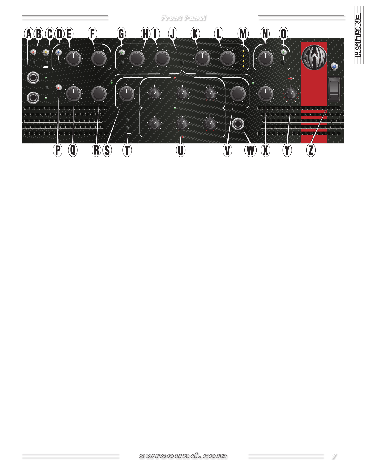
A. INPUTS Plug into either (or both) of the input jacks using a
shielded instrument cable. Press Input Select to choose either
input 1 or 2 to be the active jack as indicated by the LEDs.
The rear panel In jack {LL} can be used instead of input 1 on the
front panel; useful for connecting wireless receivers. NOTE: If
both of these jacks are used at the same time, the front panel
jack overrides the rear panel jack.
• TIP: To overdrive the first tube stage of the preamp, connect
an external preamp inline between your instrument and the
input. For the best pure-tube overdrive sound, boost the output of your external preamp, then dial in a clean Gain setting
using the PreAmp Clip LED {P}. (The Preamp Clip LED does
not monitor the very first preamp tube stage to allow you to
isolate it and overdrive it independent of the Gain controlled
stage of the preamp.)
B. MUTE Press in to disable all output from the unit, except
Tuner Out {KK}; useful when switching or tuning instruments or
during breaks.
C. PAD
cleaner response from high-output instruments.
D. BASS INTENSIFIER Press in to engage the Bass Intensifier
circuit as indicated by the LED. The Bass Intensifier boosts
a chosen set of low frequencies combined with a smooth,
fast-acting compressor, providing radical boosts without
overdriving the amplifier; useful for heavier sections of a tune.
Bass Intensifier can also be engaged from the footswitch.
E. LEVEL Adjusts the strength of the Bass Intensifier effect.
F. CUTOFF Limits the frequency range that the Bass Intensifier
operates in from below 80Hz to below 200Hz.
Press in to reduce input sensitivity by –10dB; useful for
G. COMPRESSION
Press in to engage the Compressor circuit
as indicated by the LED. Compression moderates signal level
as it peaks, according to the way you have controls {H, I, K and
L} set.
H. THRESHOLD
Sets the signal level at which Compression
engages. Turn fully counter-clockwise for maximum sensitivity.
Note that Gain {Q} level and instrument output are what actually trigger the Compressor.
I. RATIO
Adjusts how much compression is applied once it
has been triggered. For example, at 1:1 there is no compression. With a ratio of 2:1, an increase of 10 dB will be needed to
increase the output signal level by 5 dB over the threshold. At
10:1, an increase of 10 dB will only increase the output signal
level by 1 dB. (Many consider ratios of 10:1 and greater to be
hard limiting.)
J. COMP POSITION Press to alternate the position of the
Compressor circuit in the signal path from before most of the
tone shaping controls to after, as indicated by the LEDs. See
Block Diagram on page 11.
K. ATTACK Adjusts the rate that Compression engages once
the the signal level rises above the threshold; useful for fine
tuning the transparency of the Compressor effect.
L. RELEASE
Adjusts the rate that Compression disengages
once the signal level drops below the threshold; useful for fine
tuning the transparency of the Compressor effect.
M. METER
tion in dB.
Four LEDs indicate the actual amount of gain reduc-
7

Front Panel
N. BOOST LEVEL Adjusts the level of signal boost.
O. BOOST Press in to engage the Boost circuit; useful for solos.
Boost can also be engaged from the footswitch.
P. PREAMP CLIP LED
occurs anywhere in the preamp signal path before the Effects
Loop. For the cleanest sound, set Gain {Q} and other front panel
controls so that the Preamp Clip LED barely flickers at your
instrument’s peak output levels. Note that preamp clipping
is not harmful to your amplifier (unlike power amp clipping),
therefore reduce Gain only if you hear unwanted preamp distortion.
Q. GAIN Adjusts the signal level of the preamplifier. Your equal-
ization, tone and effect levels all contribute to the preamp signal level and should be adjusted before Gain. NOTE: Gain is the
primary control for setting the output level of Effects Send {FF}.
R. AURAL ENHANCER™
the Aural Enhancer brings out the fundamental low notes of
the bass, brightens high-end transients and reduces certain
frequencies that “mask” the fundamentals. The ultimate effect is
a more transparent sound that opens up the sibilant characteristics of all instruments without being harsh.
How the Aural Enhancer works: Think of it as a variable tone
control that changes frequency range AND level according to
where you set the Aural Enhancer control:
As you rotate the control clockwise from the “MIN” position,
you are elevating low, mid, and high frequency levels in ranges
that are different, yet complementary to the Bass and Treble
tone controls. The “2 o’clock” position—a favorite for many
players—brings out both low end fundamentals and crisp highs
while at the same time, adds a little lower midrange helping you
to cut through the band. Then, as you rotate further clockwise,
selected mids will drop off—specifically, a group of frequencies
centered around 200Hz. While apparent, the Aural Enhancer is
gentle compared to the extreme effects you can create with the
basic tone controls.
S. BASS Adjusts low-frequency signal response ±15dB centered
around 70Hz.
Illuminates when clipping (overdriving)
A trademark SWR® feature for 20 years,
T. EQUALIZER SELECT
dent 3-band equalizers by pressing "1/2" or use both together
as one 6-band equalizer by pressing "1+2" as indicated by the
LEDs. EQ Select can also be engaged from the footswitch (hold 1
second for 1+2).
U. SEMIPARAMETRIC EQUALIZERS First, use Equalizer
Select {T} to choose the Equalizer set that you want to use, then
use the corresponding controls to make adjustments. Each EQ control has an inner knob and
outer ring: the inner Level knob adjusts signal
response (±15dB) in the range set by the outer
Frequency ring knob. NOTE: Any EQ control with
Level set to “0” will have no effect on your signal.
TIP: If you need to “cut through” the band, try boosting
response in the 200–400Hz range. If you like a more transparent
or “scooped” sound, try cutting in the 800Hz range.
V. TREBLE Adjusts high-frequency signal response ±15dB cen-
tered around 3kHz.
W. FOOTSWITCH Plug in the (included) footswitch with any
length guitar or speaker cable to enable remote selection of the
Bass Intensifier, EQ Select, Effects Loop and Boost as indicated
by the LEDs. Multiple footswitches can be connected together
for multiple access points (stage left and stage right footswitches)!
X. EFFECTS BLEND Controls your effects level, or more precise-
ly, the ratio of direct signal (dry) mixed with effects loop signal
(wet). Set to "DRY" when not using any Effects Return jacks {FF}.
Y. MASTER VOLUMES
separately (stereo/bi-amp), or as one (mono/bridge), according
to the Normal/Bridge {PP} selector on the rear panel:
• Normal Mode—the center knob is left master and the outer
ring knob is the right master volume.
• Bi-Amp Mode—the center knob is high-frequency level control
and the outer ring knob is the low-frequency level control.
• Bridge Mode—the center knob is the master volume and the
outer ring knob is disabled.
You can switch between two indepen-
Adjusts the output of the power amps
Z. POWER SWITCH Switches the unit ON-OFF as indicated by the
LED. To reduce the risk of hearing loss and equipment damage,
please turn both level knobs {Y} down to "Min" before switching
the Power ON!
8
Rear Panel
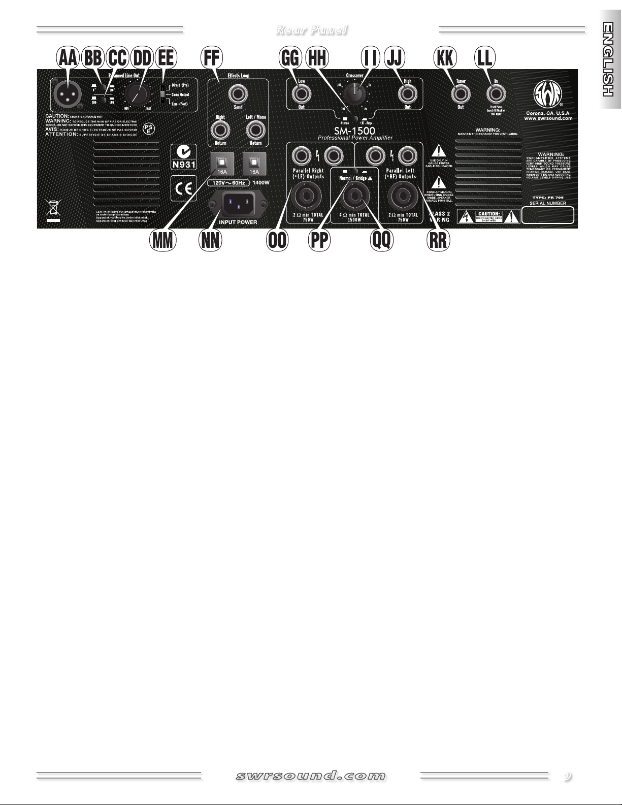
AA.
BALANCED LINE OUTPUT A fully featured, true electronical-
ly-balanced XLR jack for output to studio and live performance
mixing consoles.
BB.
0° / 180° Press to reverse the polarity of the Balanced Line
Out jack; useful for reducing phasing problems that may occur
when playing in locations with non-standard wiring or when
combining Line Output with miked cabinet signal. Normally,
leave this switch out.
CC.
GROUND / LIFT Disconnects the ground connection (pin-1)
from the Balanced Line Out jack to reduce ground loop noise
generated from non-standard wiring. Normally, leave this
switch out.
DD.
LEVEL Adjusts the output level of the Balanced Line Out jack
to accommodate a variety of sound equipment connections
and input sensitivities.
EE. DIRECT / COMPRESSOR OUTPUT / LINE Choose the point
in the signal path to connect the Balanced Line Out jack. See
Block Diagram on page 11.
• Direct (Pre)Just after the first stage–no EQ. Most like a Tube
D.I. (direct box).
• Comp OutputDepends on the Comp Position switch {J}.
Always post Gain and Aural Enhancer, but either pre or post
Bass Intensifier and EQ circuits.
• Line (Post)After all preamp circuits, including Boost and
Effects. Not affected by Master Volume {Y}.
FF. EFFECTS LOOP TRS1 multipurpose jacks—Send provides a
preamp output and includes onboard tone shaping. Output
level is primarily controlled by Gain {Q}. Effects Return (wet)
signals are mixed with the onboard preamp (dry) signal in any
ratio set by the Effects Blend control {X}. Effects Loop can be
bypassed from the footswitch.
The effects loop on the SM-1500 is located on a "side chain"
circuit, a design used in studio equipment to isolate the effects
from the main circuit. This provides the full sound of your
instrument AND allows the diversity of your external effects to
come through. The effects circuit is also located after the gain
stages in the preamp signal path to bypass the noise associated
with effects inline before the preamp.
• Effects Devices: Connect Send to your effects device input and
the effect's output(s) to the Left/Mono Return (mono effects)
or both Return jacks (stereo effects). NOTE: On your effects
device—set any wet/dry control fully to WET to prevent phasing problems and set any input level control to +4dB (or 0dB if
the unit is being overdriven). NOTE: Stereo effects are automatically summed to mono in Bi-amp and Bridge modes.
• Multiple Amplifiers: For additional output, you can connect
an auxiliary power amp to your SM-1500’s Effects Send output
(Gain on your SM-1500 will affect the volume levels of both
amplifiers). NOTE: If you wish to use an SWR® amp as an auxiliary power amp, use Mono Effects Return as the input and turn
the Effects Blend control to the maximum WET position.
• Accompaniment: Connect a CD player or drum machine to
either the Mono Return or both Stereo Return jacks. Adjust
accompaniment volume from the device and with the Effects
Blend control {X}.
GG.
LOW OUT TRS1 line level, 1/4" output. Supplies low frequen-
cies; useful for connection to an external power amplifier in a
bi-amp configuration. NOTE: This output is always active, independent of the positions of the mode switches {HH and PP}.
HH.
STEREO / BIAMP Selects a core mode of operation for the
SM-1500 power amplifiers—when not in Bridge mode {PP}:
• Stereo ModeThe power amplifiers operate separately as left
and right channels. In Stereo Mode, use both Volume knob {Y}
sections as labeled ("Left" and "Right").
• Bi-Amp Mode—The power amplifiers operate separately as
low– and high–frequency channels. In Bi-Amp Mode, use both
Volume knob {Y} sections, "Right" for low frequencies and "Left"
for high frequencies. (Stereo effects will be summed to mono.)
9
Rear Panel
II. CROSSOVER (Bi-amplifier control) Sets the frequency at
which your signal is split into high and low components. This
always affects the Low and High Out {GG and JJ} jacks. This only
affects the *LF and *HF speaker Outputs {OO and RR} when *BiAmp mode {HH} is selected.
JJ.
HIGH OUT TRS1 line level, 1/4" output. Supplies high frequen-
cies; useful for connection to an external power amplifier in a
bi-amp configuration. NOTE: This output is always active, independent of the positions of the mode switches {HH and PP}.
KK.
TUNER OUT Plug your instrument tuner in here. This TRS1
output can also be used as an always-active, tube-influenced
direct output.
LL.
IN An alternate input to input 1 on the front panel; useful for
wireless receivers. This input is disabled when a plug is inserted
into input 1 on the front panel.
MM.
MAIN BREAKERS Protects the power amplifiers from electri-
cal faults and circuit overloads. If a breaker has tripped (button
pops out), switch the Power {Z} OFF and allow the unit to cool
down. Inspect your speakers, all connections and other equipment for damage before pressing each circuit breaker back in
to reset them.
NN.
POWER CORD SOCKET Connect the included** power cord
to a properly wired AC electrical outlet in accordance with the
voltage and frequency ratings specified on the rear panel of
your amplifier.
** The SM-1500 uses a heavy duty power cord to supply the
high power requirements. To ensure safe operation: If
an extension cord is required, use only one extra-heavy
gauge cord (10 AWG or heavier) that is no longer than
absolutely necessary.
OO.
PARALLEL RIGHT LOW FREQUENCY SPEAKER OUTPUTS
Connect right channel (or low frequency) speakers to these
three jacks in any combination. The total impedance load of
these speakers should ideally be 2 ohms and must never be less
than 2 ohms. The power handling capacity of these speakers
must be at least 750 watts.
The SM-1500 furnishes both 1/4" and Speakon® speaker connections. Use the Speakon® jacks whenever possible to take
advantage of their superior electrical efficiency and secure
connectors. All three jacks on each side are full range and wired
in parallel. Read the Speaker Guidelines section below before
connecting speakers.
PP.
NORMAL / BRIDGE SWITCH Selects a core mode of opera-
tion for the SM-1500 power amplifiers. Each mode uses different
speaker outputs and master volumes. Turn OFF the SM-1500 while
switching modes and connections. Use the tip of a pen to reach the
recessed button:
• Normal ModeThe power amplifiers operate separately as
right and left channels (in Stereo mode {HH}) or as low and high
channels (in Bi-Amp mode). In Normal Mode: use the Parallel
Right (*LF) and Left (*HF) speaker Outputs {OO and RR} and
both Volume knob {Y} sections.
• Bridge ModeThe power amplifiers are bridged together to
operate as one monolithic power block. In Bridge mode: use
the one center speaker output {QQ} and the inner Volume {Y}
knob alone.
QQ.
MONO BRIDGE MODE SPEAKER OUTPUT One Speakon®
speaker output jack is available in Bridge Mode. The total
impedance load of this speaker(s) should ideally be 4 ohms and
must never be less than 4 ohms. The power handling capacity
of this speaker(s) must be at least 1500 watts. Read the Speaker
Guidelines section below before connecting speakers.
RR.
PARALLEL LEFT HIGH FREQUENCY SPEAKER OUTPUTS
Connect left channel (or high frequency) speakers to these
three jacks in any combination. The total impedance load of
these speakers should ideally be 2 ohms and must never be less
than 2 ohms. The power handling capacity of these speakers
must be at least 750 watts.
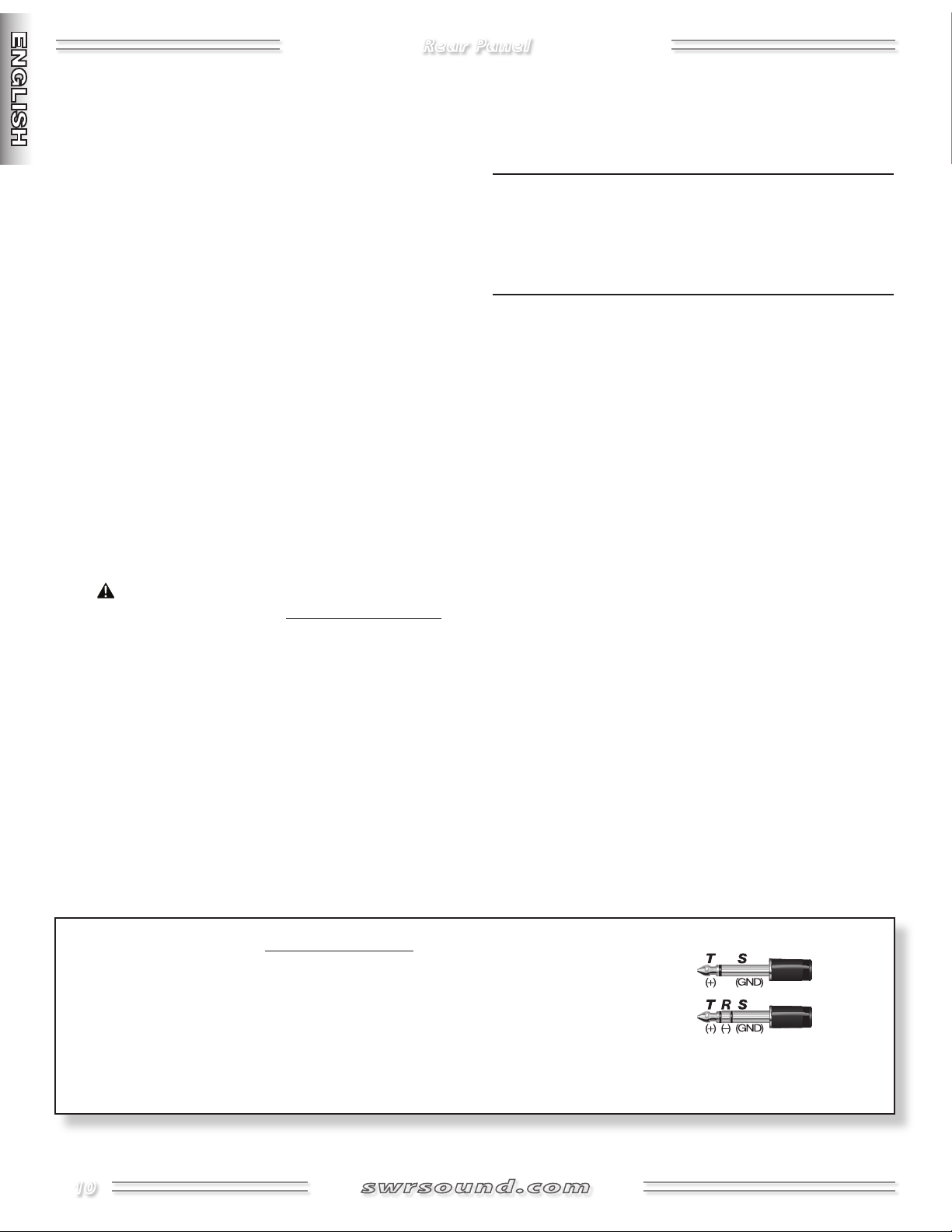
1
TRS Balanced Jacks
NOTE: Jacks {FF, GG, JJ and KK} are balanced TRS (Tip/Ring/Sleeve) types and are designed
to accept either TRS or TS (Tip/Sleeve) plugs:
Tip=positive (+)
Ring=negative (–) and
Sleeve=ground.
While standard shielded TS "mono" guitar cables may certainly be used, the use of "stereo" TRS cables may improve signal-to-noise ratio
and/or reduce hum, especially when longer connections are required.
10
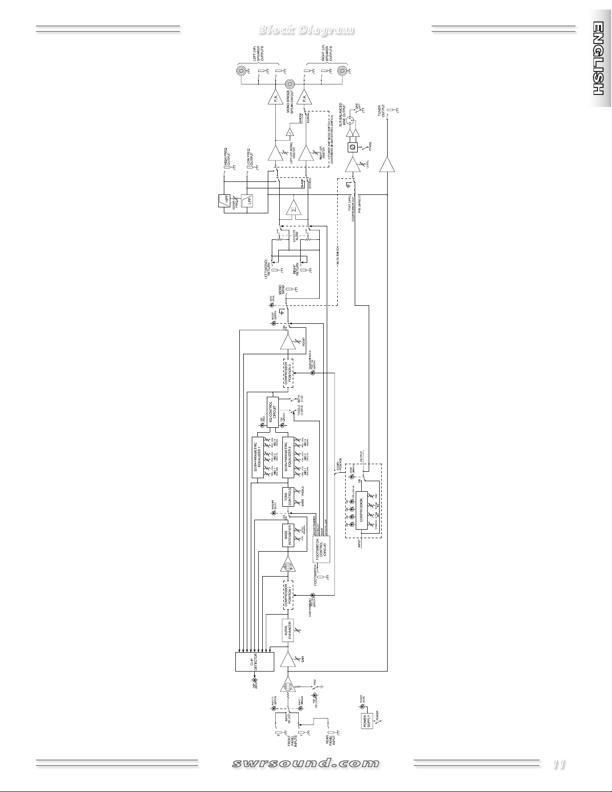
Block Diagram
11
Speaker Guidelines
• DO NOT connect a speaker load with a total impedance below the minimum rating of your amplifier to
prevent damage to your equipment.
• DO NOT connect speaker(s) with a total power han
dling capacity that is less than the power output
rating of your amplifier to prevent damage to your
equipment.
• ALWAYS switch your system power OFF before con
necting or disconnecting speakers.
• ONLY use unshielded speaker cable of 18 gauge or
heavier (16 or 14 gauge) for speaker connections.
Shielded instrument cable WILL NOT work and may
damage your equipment.
• ONLY connect one amplifier to each speaker load.
Two amplifiers connected to a single load WILL NOT
work and may damage your equipment.
Use the impedance and power ratings on your amplifier and
speakers to determine if a particular combination of speakers
is appropriate for your amplifier. NOTE: All SWR® bass speaker
enclosures, as well as most others, will be connected in parallel
(NOT series) when linked (daisy-chained) together. Therefore,
these guidelines apply only to parallel speaker configurations.
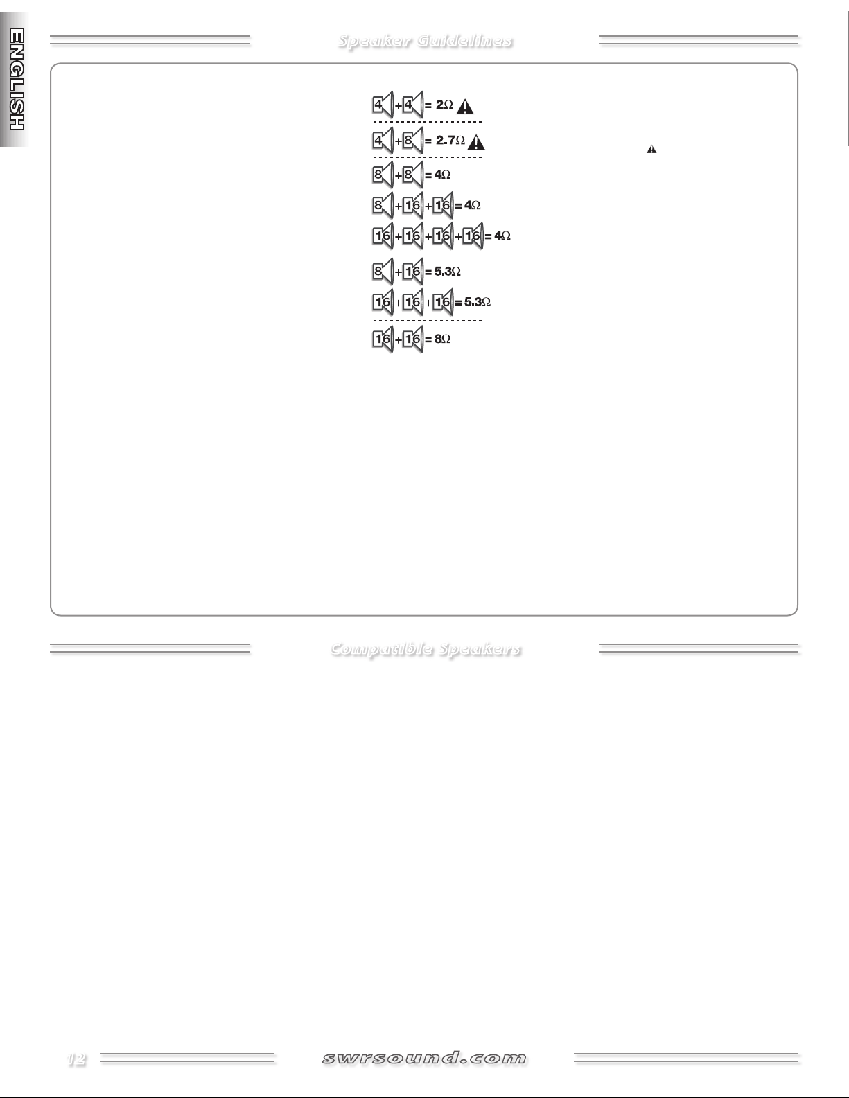
-
-
The speaker illustration gives you the total imped-
ance load calculations for various speaker impedance
combinations (=ohms). The ideal speaker load (total
impedance) is equal to the minimum impedance
rating of your amplifier. Operating below the
amp's minimum impedance rating can overheat
your amplifier and cause damage. Operating above
the amp's minimum impedance rating, while safe,
reduces the amplifier’s maximum power output.
Something else to consider: You can obtain the
same group total impedance load from different
combinations of speaker impedances (see illustra-
tion). If each speaker in a group has the same imped-
ance, each speaker will receive the same amount of
power from your amplifier. However, if impedances
are not all equal, the lowest impedance speakers will
get the most power. For example, if you connect an 8
and a 16 speaker to an amp output of 30 watts, the 8–ohm
speaker will receive about 20 of those watts (and be twice as
loud as the 16-ohm speaker). Take this into consideration when
calculating power handling capacities and when positioning your
bass speaker enclosures.
For an in-depth discussion of setup tips for amplifiers and speakers
(including a look at impedance and power rating issues), visit the
Support area of the SWR website at www.swrsound.com.
Compatible Speakers
1,500 watts is far more power than most bass speaker systems are
equipped to handle, so use caution when using the bridged mode
of this amplifier.
sor when using the bridged mode and, if you have any doubts
about your speakers’ power-handling capabilities, check the owner’s
manual and product specifications before operation.
Each side of the amplifier is capable of 750 watts @ 2 ohms, 450 watts
@ 4 ohms and 250 watts @ 8 ohms. Ensure that your speaker system
has power-handling capabilities that match or exceed these powerhandling specifications. Using two or more cabinets per side will
optimize the amplifier's headroom and power, but remember that
each additional speaker also reduces the total impedance (ohms)
connected to the amp. For example, one 8-ohm Goliath III cabinet is
rated to handle 700 watts; if you combine two of these cabinets, the
combined power handling would be 1,400 watts, but the impedance
would be lowered to 4 ohms (please see the “Speaker Guidelines”
section of this manual for further information).
It is recommended that you engage the compres-
Minimum Speaker Ratings
The combined speaker impedance and wattage ratings at each output should be no lower than the following.
In Stereo, Dual-Mono, or Bi-Amp modes (per side):
•2 ohm 750W •4 ohm 450W; •8 ohm 250W
In Bridged mode:
•4 ohm 1500W •8 ohm 900W
12
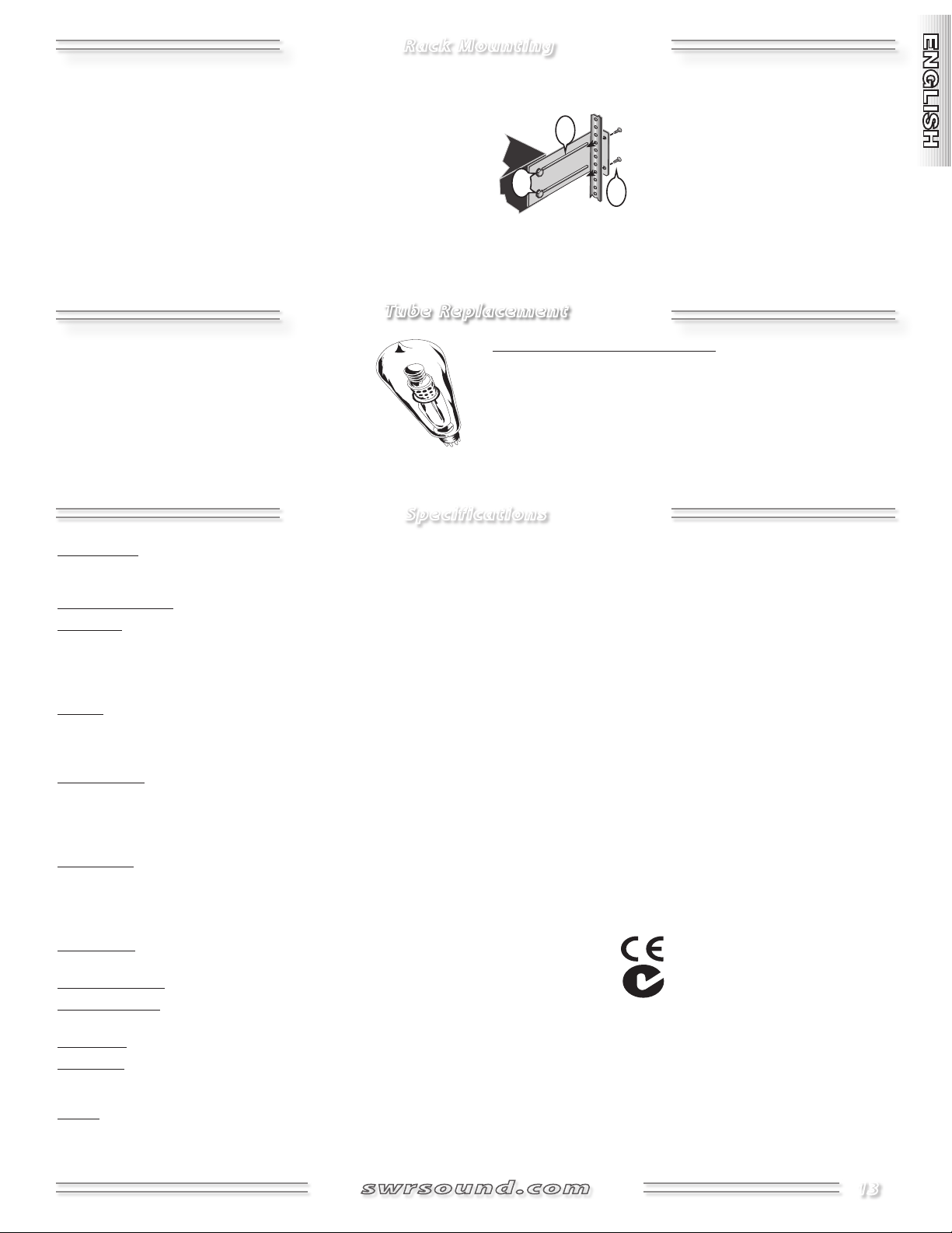
Rack Mounting
The SM-1500 requires three full rack spaces and because of its
weight, should only be mounted at the bottom of a rack case that
is equipped with both front and rear rack rails. Rear rack ears are
included for this purpose. If mounted in an upper rack space or in a
rack case with only front rails, additional support must be installed
below the SM-1500 to prevent flexing of the amplifier's chassis which,
over time, can damage the amplifier and void warranty coverage.
To mount the rear rack ears to your SM-1500, position the ears (1) and
loosely attach them to the SM-1500 chassis with the included bolts
(2). Next, support the SM-1500 in place while you attach the rear rack
bolts (3) as shown. When in place and supported, tighten all bolts.
Tube Replacement
A 12AX7 dual triode vacuum tube (valve) is at
the core of your SM-1500 pre-amplifier. Typically
a 12AX7 tube will last several years, but through
heavy use and frequent transportation jarring, it is
possible to have a tube last less than a year.
Specifications
Please routinely check the mounting and chassis screws which can
vibrate loose due to transportation and use. We recommend that at
least once a month that the SM-1500 be
removed from the rack case and all outside
screws be tightened and all connections in
your rack case be checked to preserve the
beauty and reliability of your equipment.
When to replace the preamp tube: Sometimes, tubes become
noisy or “microphonic” (the amp sounds like a glass chime tinkling
during certain notes) as they wear out, but other times, tubes will
fail without warning. If your amplifier stops working and other
possible causes have been eliminated (breakers, cords, etc.), have an
authorized service center inspect your amplifier for tube failure.
PART NUMBERS 44-01400-000 (120V, 60Hz) USA 44-01403-000 (240V, 50Hz) AUS
44-01404-000 (230V, 50Hz) UK 44-01406-000 (230V, 50Hz) EUR
44-01407-000 (100V, 50/60Hz) JPN
POWER REQUIREMENT 1400W
POWER AMP MINIMUM IMPEDANCE: 4 (Bridge Mode);
2 per channel (Normal, Stereo, Bi-Amp Modes)
SENSITIVITY: 1.2V RMS, 1kHz @ Mono Return, Effects Blend at WET, Volume at MAX
POWER OUTPUT: 1500W @ 4 (Bridge Mode);
750W @ 2 per channel (Normal, Stereo, Bi-Amp Modes)
PRE AMP INPUT IMPEDANCE: >820k (Front panel Inputs);
10kΩ (Rear panel Input)
SENSITIVITY FOR FULL POWER: 13mV @ 1kHz, Gain and Volume at MAX, all Bass, Mid and Treble controls flat (center detent),
Aural Enhancer at mid position, Effects Blend at DRY, Bass Intensifier, Compression and Boost OFF
TONE CONTROLS BASS: ±15dB @ 70Hz
TREBLE: ±15dB @ 3kHz
VARIABLE SEMI-PARAMETRIC EQ: MID 1: ±15dB @ 30Hz–200Hz
MID 2: ±15dB @ 165Hz–1.1kHz
MID 3: ±15dB @ 900Hz–6kHz
COMPRESSION GAIN REDUCTION: –22dB maximum, selectable PRE or POST EQ
THRESHOLD: –10dBV to +10dBV
RATIO: 1:1 to 20:1
ATTACK TIME: 10mS to 600mS
RELEASE TIME: 500mS to 5.5S
EFFECTS LOOP SEND IMPEDANCE: 220
RETURN IMPEDANCE: 10k Balanced
BALANCED LINE OUT SEND IMPEDANCE: 50
ACTIVE CROSSOVER RESPONSE: 3–pole (18dB/octave) Butterworth
CROSSOVER FREQUENCY: 100Hz–2.0kHz
FOOTSWITCH 4–button (0072471000)
DIMENSIONS HEIGHT: 5.5 in (14 cm)
WIDTH: 19 in (48.3 cm)
DEPTH: 19.5 in (49.5 cm)
WEIGHT 67 lb (30.4 kg)
Product specifications are subject to change without notice.
13

Amplificador de bajo SM-1500
¡Felicidades y gracias por su compra del amplificador de bajo
SWR® SM-1500™!
El SM-1500 sigue la tradición de innovación establecida por el
fundador de SWR, Steve W. Rabe, en 1984. Como respuesta a
los consejos y sugerencias de los mejores bajistas de estudio
de L.A. del momento, que le pidieron sonar en directo con
la misma calidad que en sus monitores de estudio, Rabe
desarrolló un concepto completamente nuevo en cuanto a
amplificación de bajo; y fue así como nació el “sonido SWR”.
El PB-200™ fue el primer amplificador de bajo híbrido con
previo a válvulas/etapa de potencia de estado sólido y que
disponía del ahora ya clásico preamplificador y circuitería de
intensificador Aural Enhancer™ de SWR. Este fue un producto
que dio origen a una auténtica revolución en la amplificación
de bajo y que ofrecía un sonido cristalino y de alta calidad
tanto para directo como en estudio.
Su nuevo amplificador profesional de bajo SM-1500 le ofrece todo el
rendimiento, potencia y sonido SWR® aclamado y buscado por los
mejores bajistas del mundo:
• Doble etapa de potencia con tres modos de funcionamiento
• Modo puente o bridge (mono) —1.500 watios @ 4 ohmios
• Modo stereo—750 watios @ 2 ohmios (por lado)
• Modo Bi-Amp—con frecuencia crossover ajustable
• Previo a válvulas con una doble válvula de triodo 12AX7
• Dos entradas en el panel frontal más una en el trasero con
interruptor selector de entrada para conexión de diversas
configuraciones de bajo
El siguiente paso en la evolución de SWR vino en 1985, con
la presentación del ahora legendario amplificador SM-400™.
Esta unidad era el primer amplificador de bajo realmente
stereo con un bucle de efectos stereo y entradas tanto para
instrumentos activos como pasivos. En 1987 le siguió el ahora
standard industrial 4x10 Goliath, el primer recinto acústico
de rango completo diseñado para bajo que disponía de un
tweeter para frecuencias agudas.
En 1991, nuestra incansable búsqueda de más potencia y
funciones profesionales dio paso a la creación del SM-900™;
uno de los amplificadores de bajo más solicitados tanto por
músicos de directo como por estudios y empresas de alquiler
de equipos. En 1993, el SM-400 fue mejorado y renombrado
como SM-400S™, con también más mejoras y otros modelos
que dieron paso al SM-500™ en 1999.
Fieles a la tradición de SWR, el SM-1500 es un producto
realmente innovador que es el resultado de años de
investigación y desarrollo, unido todo ello al contacto directo
con algunos de los mejores bajistas del mundo. En el SM1500, hemos combinado la amplia gama de funciones de
nuestra familia de amplificadores SM; posibilidades stereo y
bi-amp con una impresionante capacidad de potencia: 750
watios por lado en funcionamiento stereo o mono dual o
1500 watios @ 4 ohmios puenteado en mono.
• Famso modelado de sonido con SWR® Aural Enhancer
• Compresión profesional con selección de posición de Comp
• Cuatro posibilidades seleccionables de pedalera
• Intensificador de bajo para el máximo impacto
• Realce para un mayor acento en los solos
• Tres configuraciones de EQ semiparamétrico—elija entre dos
EQ de 3 bandas independinetes o combínelos en un único EQ
de 6 bandas
• Bucle de efectos stereo/mono con control de mezcla de
efectos
• Tradicionales controles de tono graves/agudos
• Salidas de altavoz en speakon® y 6,3 mm
• Salida en XLR balanceado con modos de línea, salida de compresor
y salida directa de válvulas, además de control de nivel, e
interruptores de fase y anulación de toma de tierra
Además, hemos añadido nuestra famosa circuitería Bass
Intensifier™; (un circuito de realce perfecto para solos) y un
compresor controlado a válvulas que puede ser conmutado
tanto antes como después de la sección EQ del amplificador.
Sencillamente, el SM-1500 es una maravilla de diseño a la
vez que una herramienta potente y versátil para el bajista
profesional.
Estamos seguros que disfrutará durante años del SM-1500 y le
agradecemos de antemano el “dar el paso” con SWR.
14
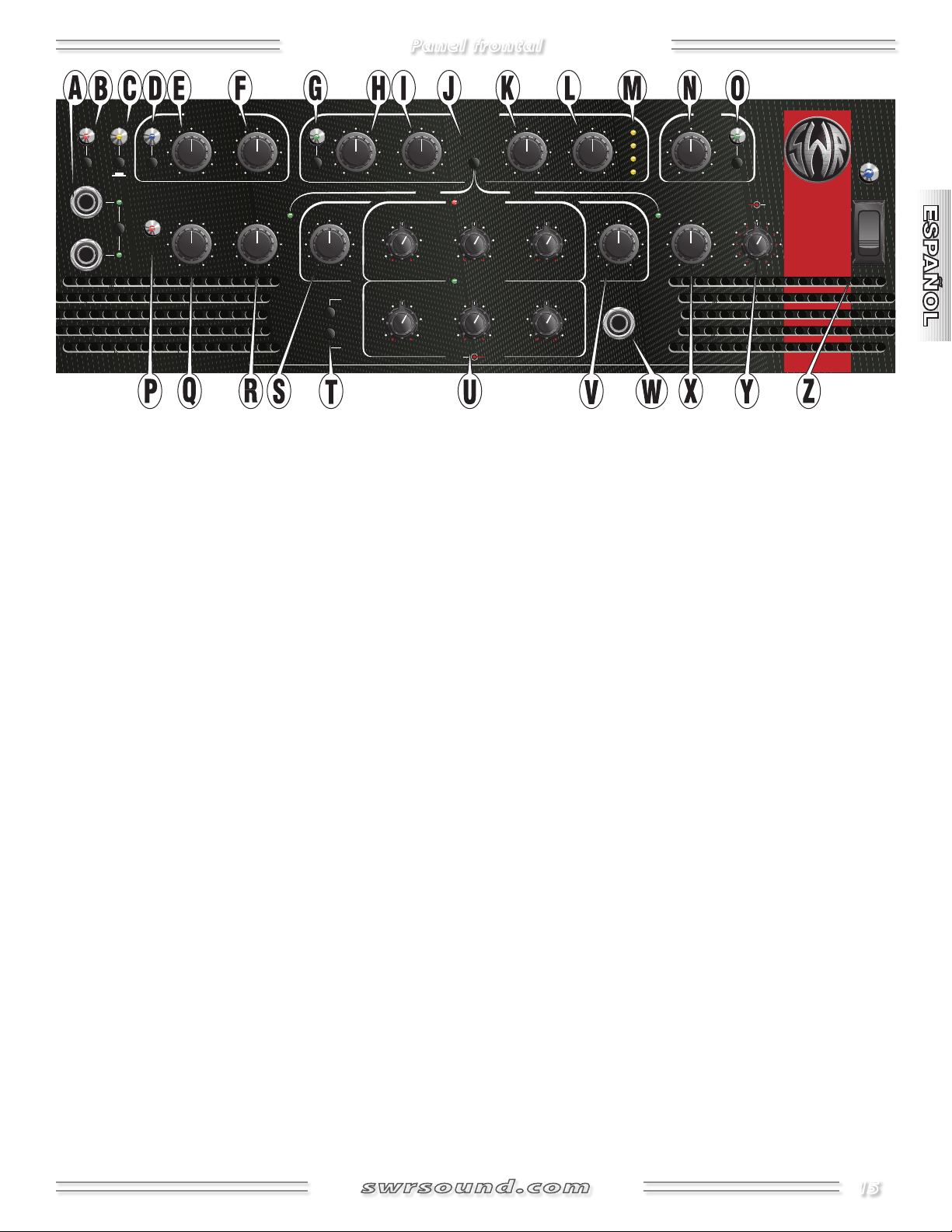
Panel frontal
Input
Select
1
2
-10 dB
Pad
Mute
Preamp
Clip
MIN
MAX
MIN
MAX
Aural
Enhancer
Gain
EQ
Select
1 + 2
1 / 2
MIN
MAX
Level
80
200
Cutoff
-15
+15
Bass
-10
-5
+5
+10
Threshold
Ratio
Position
Comp
MIN
MAX
Attack
MIN
MAX
-2
-8
-18
-4
Release
ON
Power
Footswitch
Volume
Effects
Blend
-15
+15
Treble
Right
Left
Bass Intensifier
PRE EQ
POST EQ
Freq
Level
Equalization 1
Equalization 2
Compression
Boost
SM-1500
MIN
MAX
1 : 1
2 : 1
10 : 1
20 : 1
120
180
45
35
-15
+15
Mid 1
80 95
Mid 3
650
1k
250
180
-15
+15
Mid 2
450 530
3.4k
5k
1.3k
1k
-15 +15
2.3k 2.8k
120
180
45
35
-15 +15
Mid 1
80
95
3.4k
5k
1.3k
1k
-15
+15
Mid 3
2.3k
2.8k
650
1k
250
180
-15
+15
Mid 2
450
530
MIN
MAX
DRY
WET
A. INPUTS Conecte su instrumento a una (o ambas) tomas de
entrada usando un cable de instrumento con blindaje. Pulse
Input Select para elegir entre la entrada 1 ó 2 como conector
activo (será indicado por el LED).
Puede usar el conector In {LL} del panel trasero en lugar de la
entrada 1 del panel frontal; esto es muy útil para la conexión
receptores inalámbricos. NOTA: Si usa ambas tomas a la vez, la
del panel frontal tendrá prioridad sobre la del panel trasero.
• CONSEJO: Para saltarle la primera fase a válvulas del previo,
conecte un preamplificador exterior en línea entre su
instrumento y la entrada. Para conseguir el mejor sonido de
saturación a válvulas, realce la salida de su previo exterior y
ajuste un valor limpio de ganancia usando el piloto PreAmp
Clip {P}. (Este piloto no monitoriza la primera fase a válvulas
del previo para permitirle aislarla y saturarla de forma
independiente de la etapa controlada por ganancia del previo).
B. MUTE Pulse este interruptor para desactivar todas las salidas
de la unidad, excepto la de afinador {KK}; esto es muy útil
cuando afine su instrumento o durante las pausas.
C. PAD Pulse en este botón para reducir la sensibilidad de
entrada en –10 dB; esto resulta muy útil para conseguir una
respuesta más limpia de instrumentos de alta salida.
D. BASS INTENSIFIER
Intensificador de bajos, tal como verá indicado con el piloto.
Este circuito intensifica un grupo determinado de frecuencias
rápida para conseguir un realce radical sin sobrecargar el
graves a la vez que activa un compresor suave y de activación
amplificador; esto es muy útil para las secciones más potentes
y pesadas de una canción. También puede activar este circuito
desde la pedalera.
E. LEVEL Ajusta la fuerza del efecto del Intensificador de bajos.
F. CUTOFF Limita el rango de frecuencias en el que opera el
Intensificador de bajos a por debajo de 80 Hz o por debajo de
200 Hz.
G. COMPRESSION
Pulse aquí para activar el circuito compresor,
tal como verá indicado por el LED. La compresión modera el
nivel de la señal en los picos, de acuerdo a los ajustes que haya
realizado en los controles {H, I, K y L}.
H. THRESHOLD
Ajusta el nivel de señal en la que se activará
la compresión. Gírelo completamente a la izquierda para la
máxima sensibilidad. Tenga en cuenta que el nivel de ganancia
{Q} y la salida del instrumento es lo que realmente dispara el
compresor.
I. RATIO Ajusta la cantidad o porcentaje de compresión que se
aplicará una vez que sea activado este efecto. Por ejemplo, con
1:1 no habrá compresión. Con un ratio de 2:1, será necesaria
un aumento de 10 dB para que el nivel de la señal de salida
aumente en 5 dB por encima del umbral. En 10:1, un aumento
de 10 dB hará que el nivel de la señal de salida aumente en
solo 1 dB. (Muchos consideran los ratios como 10:1 y superiores
como una limitación dura en lugar de una compresión).
J. COMP POSITION Pulse aquí para cambiar la posición del
circuito compresor en la ruta de señal entre antes de la
mayoría de los controles de modelado del tonoo después de
estos, tal como será indicado por los pilotos. Vea el Diagrama
de bloques en la página 19.
Pulse aquí para activar el circuito de
K. ATTACK
una vez que el nivel de la señal ha pasado por encima
Ajusta la velocidad a la que el compresor se activa
del umbral; esto es muy útil para ajustar con precisión la
transparencia del efecto compresor.
L. RELEASE Ajusta la velocidad con la que el compresor se
M. MEDIDOR Cuatro pilotos LED que indican la cantidad real de
desactiva una vez que el nivel de la señal cae por debajo del
umbral; útil para ajustar con precisión la transparencia del
efecto compresor.
reducción de ganancia en dB.
15

Panel frontal
N. BOOST LEVEL Ajusta el nivel de realce de la señal.
O. BOOST Pulse aquí para activar el circuito Boost o de realce;
muy útil para solos. También lo puede activar desde la pedalera.
P. LED PREAMP CLIP
saturación (clip) en algún punto de la ruta de la señal del previo
antes del bucle de efectos. Para conseguir el sonido más limpio
posible, ajuste Gain {Q} y el resto de controles del panel frontal
de forma que este piloto Preamp Clip parpadee ocasionalmente
en los picos de salida de su instrumento. Tenga en cuenta que
una saturación del previo no es dañina para su amplificador (al
contrario de lo que ocurre con las saturaciones de la etapa de
potencia), por lo que solo deberá reducir el nivel de ganancia si
escucha alguna distorsión no deseada del previo.
Q. GAIN Ajusta el nivel de señal del preamplificador. Sus niveles
de ecualización, tono y efectos contribuyen al nivel de señal del
previo, por lo que debería ajustarlos antes de ajustar este Gain.
NOTA: Gain es el control primordial para el ajuste del nivel de
salida del envío de efectos {FF}.
R. AURAL ENHANCER™ Un verdadero buque insignia de SWR®
desde hace 20 años, este Intensificador aural realza las notas
graves fundamentales del bajo, da más brillo a los transitorios
de super agudos y reduce determinadas frecuencias que
"enmascaran" los fundamentales. El efecto final es un sonido
más transparente que abre las características sibilantes de todos
los instrumentos sin hacer que resulten ásperos.
Así es como funciona este Intensificador Aural: Piense en él
como en un control de tono variable que cambia el rango de
frecuencia Y el nivel de acuerdo al punto en que lo ajuste:
Conforme gire el control a la derecha desde la posición “MIN”,
estará elevando los niveles de las frecuencias graves, medias y
agudas en rangos que son diferentes, pero complementarios a
los de los controles de tono Bass y Treble. La posición de “las 2 en
punto”—la preferida por muchos músicos—realza a la vez tanto
los fundamentales super graves como los agudos más brillantes
y añade una ligera reducción en el rango medio para ayudarle
a que su sonido sobresalga del resto del grupo. Después,
conforme más gire el mando a la derecha desde allí, habrá
una serie de medios que serán eliminados—específicamente,
un grupo de frecuencias centradas alrededor de los 200 Hz.
Aunque sus efectos son aparentes, este Intensificador Aural es
sutil en comparación con los efectos extremos que puede crear
a partir de los controles básicos de tono.
S. BASS Ajusta la respuesta de la señal de frecuencias graves en
±15 dB centrado alrededor de los 70 Hz.
Se ilumina cuando se produce una
T. EQUALIZER SELECT
ecualizadores de 3 bandas independientes pulsando "1/2" o
usar ambos juntos como un único ecualizador de 6 bandas
con la opción "1+2" tal como será indicado con los pilotos.
Esta selección de EQ también puede ser conmutada desde la
pedalera (mantenga pulsado 1 segundo para la opción 1+2).
U. ECUALIZADORES SEMIPARAMETRICOS
control Equalizer Select {T} anterior para elegir
la opción de ecualización que quiera usar y use
después los controles correspondientes para
realizar los ajustes. Cada control EQ tiene un mando
interior y un anillo exterior: el mando interior Level
le permite ajustar la respuesta de señal (±15 dB) en el rango de
frecuencias que ajuste con el anillo exterior Frequency. NOTA:
Cualquier control EQ cuyo nivel esté ajustado a “0” no tendrá
ningún efecto sobre la señal.
CONSEJO: Si necesita “sobresalir” del resto del grupo, pruebe a
realzar la respuesta en el rango 200–400Hz. Si quiere conseguir
un sonido más transparente o "scoop", pruebe a aplicar un ligero
corte en el rango de 800Hz.
V. TREBLE Ajusta la respuesta de señal de las frecuencias agudas
en ±15 dB con centro alrededor de los 3 kHz.
W. FOOTSWITCH Conecte aquí la pedalera (incluida) por medio
de un cable de guitarra o de altavoz de cualquier longitud
para realizar la selección remota del Intensificador de bajo,
selecciónde EQ, bucle de efectos y Realce, tal como verá
indciado con los pilotos. Puede conectar juntas varias pedaleras
para el acceso desde varios puntos (pedaleras de parte izquierda
y parte derecha del escenario)!
X. EFFECTS BLEND Controla su nivel de efecto o, por ser más
precisos, el ratio o relación de señal directa (seca) que es
mezclada con la señal del bucle de efectos (húmeda). Ajústelo
a "DRY" cuando no utilice ninguno de los conectores de retorno
de efectos {FF}.
Y. MASTER VOLUMES
de forma independiente (stereo/bi-amp), o como una sola
(mono/bridge), de acuerdo al ajuste del selector Normal/Bridge
{PP} del panel trasero:
• Modo Normal—el mando central es el master izquierdo y el
anillo exterior es el volumen master derecho.
• Modo Bi-Amp—el mando central es el control de nivel de las
altas frecuencias y el anillo exterior el control de las graves.
• Modo Bridge—el mando central es el volumen master y el
anillo exterior queda desactivado en este caso.
Puede elegir entre disponer de dos
Primero, use el
Ajustan la salida de las etapas de potencia
16
Z. INTERRUPTOR POWER Enciende y apaga la unidad, tal como
verá indicado por el piloto. Para reducir el riesgo de daños en el
aparato y en sus oídos, coloque los dos mandos de nivel {Y} en
la posición "Min" antes de colocar este interruptor en ON!
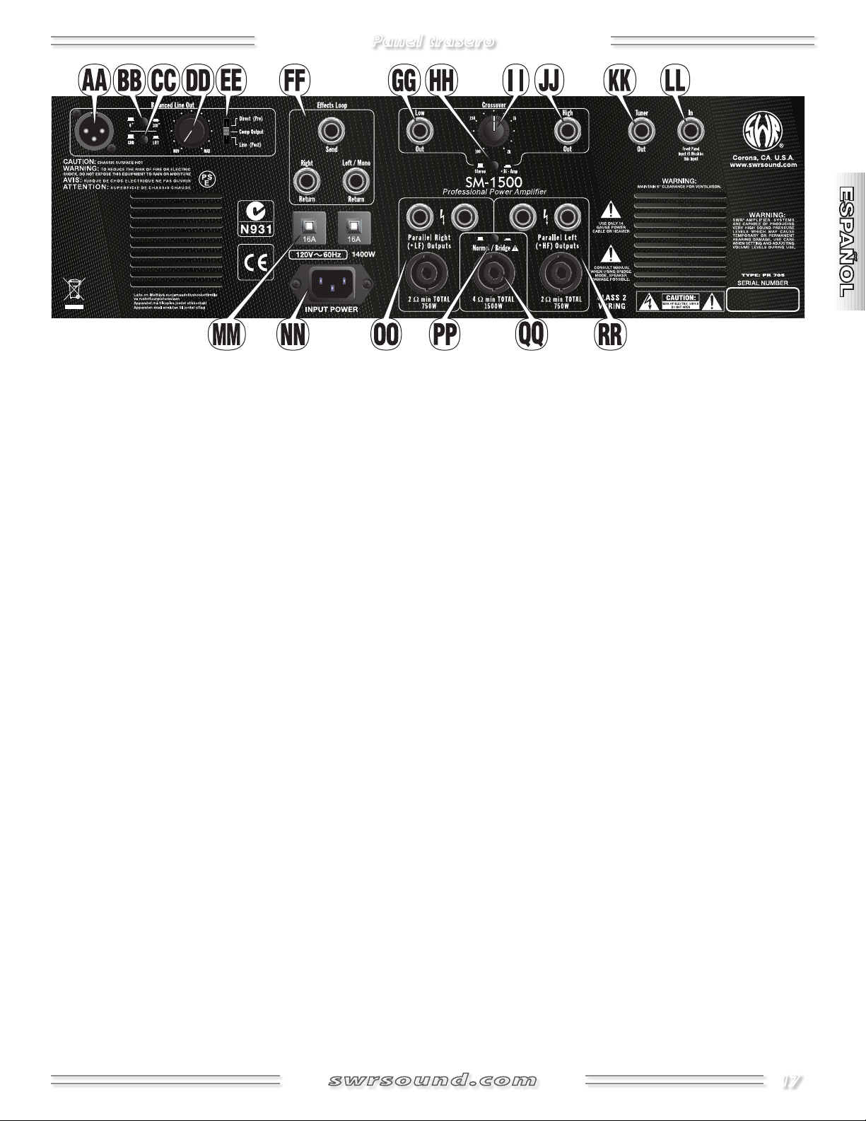
Panel trasero
AA.
SALIDA DE LINEA BALANCEADA Conector XLR balanceado
electrónicamente para dar salida a la señal a mesas de mezclas
de estudio o directo.
BB.
0° / 180° Pulse este botón para invertir la polaridad del
conector de salida de línea balanceada; esto es útil para reducir
los problemas de fase que se pueden producir al usar la unidad
en lugares con cableado no standard o cuando combine la
salida de línea con una señal captada por micro. Normalmente,
deje este interruptor sin pulsar.
CC.
GROUND / LIFT Desconecta la conexión de toma de tierra
(punta 1) del conector de salida de línea balanceada para
reducir los ruidos de bucle a tierra producidos por cableado no
standard. Normalmente, deje este interruptor sin pulsar.
DD.
LEVEL Ajusta el nivel de salida del conector de salida de
línea balanceada para adaptar esa señal a una amplia gama de
equipos de sonido y sensibilidades de entrada.
EE. DIRECT / COMPRESSOR OUTPUT / LINE Elige el punto en la
ruta de señal en el que está conectado el conector de salida de
línea balanceada. Vea el Diagrama de bloques de la página 19.
• Direct (Pre)justo después de la primera fase–no EQ. Parecido
a un D.I. (caja directa) a válvulas.
• Comp OutputDepende del interruptor Comp Position {J}.
Siempre post ganancia e intensificador aural, pero puede ser
pre o post circuitos EQ e Intensificador de bajo.
• Line (Post)Después de todos los circuitos de previo,
incluyendo los de realce y efectos. No afectado por el volumen
master {Y}.
FF. EFFECTS LOOP Conectores TRS1 multiusos—Send le ofrece
una salida de previo e incluye modelado de sonido interno.
El nivel de salida es controlado inicialmente por Gain {Q}. Las
señales de Effects Return (húmedo) son mezcladas con la del
previo interno (seca) en el ratio ajustado con el control Effects
Blend {X}. Puede anular el bucle de efectos desde la pedalera.
El bucle de efectos del SM-1500 está colocado en un circuito
de "cadena lateral", un diseño usado en los equipos de estudio
para aislar los efectos del circuito principal. Esto le ofrece todo
el sonido de su instrumento Y ADEMAS toda la diversidad
de sus efectos exteriores. El circuito de efectos está también
situado después de las fases de ganancia de la ruta de señal
de previo para anular el ruido asociado con los efectos en línea
colocados antes del preamplificador.
• Unidades de efectos: Conecte Send a la entrada de su unidad
de efectos y la salida(s) de esa unidad a Left/Mono Return
(efectos mono) o a ambas tomas Return (stereo). NOTA: En su
unidad de efectos—ajsute cualquier control húmedo/seco a
totalmente HUMEDO para evitar problemas de fase y ajuste
el control de nivel de entrada a +4 dB (o 0 dB si la unidad
está saturada). NOTA: Los efectos stereo son automáticamente
sumados a mono en los modos Bi-amp y Bridge.
• Varios amplificadores: Para una mayor salida, puede conectar
una etapa de potencia auxiliar a la salida Effects Send del SM1500 (la ganancia de su SM-1500 afectará al nivel de volumen
de ambos amplificadores). NOTA: Si quiere usar un amplificador
SWR® como etapa de potencia auxiliar, use el retorno de efectos
mono como la entrada y coloque el control Effects Blend en el
tope WET.
• Acompañamiento: Conecte un reproductor de CD o caja de
ritmos a la entrada Mono Return o a ambos retornos si es
stereo. Ajuste el volumen del acompañamiento desde la unidad
conectada y con el control Effects Blend {X}.
GG.
LOW OUT Salida TRS1 de 6,3 mm y nivel de línea. Le ofrece
una señal de bajas frecuencias; muy útil para la conexión
a una etapa de potencia exterior en en una configuración
de bi-amplificación. NOTA: Esta salida siempre está activa,
independientemente de las posiciones de los interruptores de
modo {HH y PP}.
HH.
STEREO / BIAMP Elige el modo básico de operación de las
etapas de potencia del SM-1500—cuando no está en el modo
Bridge {PP}:
• Modo StereoLas etapas actuarán por separado como canales
izquierdo y derecho. En este modo, use ambas secciones de los
mandos Volume {Y} como indican ("Izquierda" y "Derecha").
• Modo Bi-Amp—Las etapas actúan por separado como canales
de frecuencias graves y agudas. En este modo, use las dos
secciones del mando Volume {Y}, "Right" para los graves y "Left"
para los agudos. (Los efectos stereo son sumados a mono).
17
Panel trasero
II. CROSSOVER (Control Bi-amplificación) Ajusta la frecuencia a
la que su señal será dividida en componentes agudos y graves.
Esto afecta siempre a las tomas de salida Low y High Out {GG y
JJ}. Esto solo afecta a las salidas de altavoces *LF y *HF {OO y RR}
cuando haya elegido el modo *Bi-Amp {HH}.
JJ.
HIGH OUT Salida TRS1 de 6,3 mm y nivel de línea. A través
de ella es emitida una señal de altas frecuencias; esto es muy
útil para la conexión a una etapa de potencia exterior en
una configuración bi-amplificada. NOTA: Esta salida siempre
está activa, independientemente de las posiciones de los
interruptores de modo {HH y PP}.
KK.
TUNER OUT Conecte aquí su afinador de instrumento. Esta
salida TRS1 también puede ser usada como una salida directa a
válvulas y siempre activa.
LL.
IN Una entrada alternativa a la entrada 1 del panel frontal;
muy útil para receptores inalámbricos. Esta entrada queda
desactivada en cuanto haya un conector introducido en la
entrada 1 del panel frontal.
MM.
RUPTORES Protege las etapas de potencia de posibles averías
eléctricas y sobrecargas del circuito. Si uno de estos ruptores
salta (el botón sale hacia fuera), apague el interruptor Power
{Z} y deje que la unidad se refrigere. Compruebe sus altavoces,
todas las conexiones y el resto del equipo en busca de posibles
daños antes de pulsar cada uno de estos ruptores de circuito
para volver a colocarlos en su posición normal.
NN.
CONECTOR DE CABLE DE ALIMENTACION Conecte el cable
de alimentación incluido** a una salida de corriente alterna
adecuada y del voltaje y amperaje especificados en el panel
trasero del amplificador.
** El SM-1500 usa un cable de alimentación de alto
rendimiento que cumple los requisitos necesarios para
suministrar el alto nivel de corriente necesario. Para
asegurar un funcionamiento seguro: Si necesita usar una
alargadera, use solo una con cable de gran calibre (10
AWG o superior) y que sea lo más corta posible.
OO.
SALIDAS DE ALTAVOZ PARALLEL RIGHT LOW
FREQUENCY Conecte los altavoces de canal derecho (o de
bajas frecuencias) a estas tres tomas en cualquier combinación.
La impedancia de carga total de estos altavoces debería de de 2
ohmios y nunca inferior a ese valor. La capacidad de manejo de
potencia de estos altavoces debe ser de al menos 750 watios.
El SM-1500 le ofrece conexiones de altavoz tanto de 6,3 mm
como Speakon®. Use las conexiones Speakon® siempre que
pueda para sacar partido de su mayor eficacia eléctrica y su
mayor seguridad. Los tres conectores de cada lado son de
rango completo y están cableados en paralelo. Lea la sección
de guía de conexión de altavoces más adelante antes de
conectar sus recintos acústicos.
PP. INTERRUPTOR
básico de las etapas de potencia del SM-1500. Cada modo usa
distintas salidas de altavoz y volúmenes master. Apague el SM1500 cuando vaya a cambiar los modos o las conexiones. Utilice la
punta de un bolígrafo para llegar a este botón encastrado:
• Modo NormalLas etapas de potencia actúan por separado
como canales izquierdo y derecho (en el modo Stereo {HH}) o
como canales grave y agudo (en el modo Bi-Amp). En el modo
Normal: use las salidas de altavoz Parallel Right (*LF) y Left (*HF)
{OO y RR} y las dos secciones del mando Volume {Y}.
• Modo BridgeLas etapas de potencia son puenteadas juntas
para actuar como un único bloque monolítico de potencia:
use solo la salida de altavoz central {QQ} y el mando interior
Volume {Y}.
QQ.
SALIDA DE ALTAVOZ MONO BRIDGE MODE En el modo
Bridge dispone de un conector de salida de altavoz Speakon®.
La impedancia de carga total de este altavoz(es) debería ser de
4 ohmios y nunca inferior a ese valor. La capacidad de manejo
de potencia de este altavoz(es) debería ser de como mínimo
1.500 watios. Lea la sección de guía de conexión de altavoces
más adelante antes de conectar sus recintos acústicos.
RR.
SALIDAS DE ALTAVOZ PARALLEL LEFT HIGH FREQUENCY
Conecte los altavoces de canal izquierdo (o de frecuencias
agudas) a estas tres tomas en cualquier combinación. La
impedancia de carga total de estos altavoces debería de de 2
ohmios y nunca inferior a ese valor. La capacidad de manejo de
potencia de estos altavoces debe ser de al menos 750 watios.
NORMAL / BRIDGE Elige el modo operativo
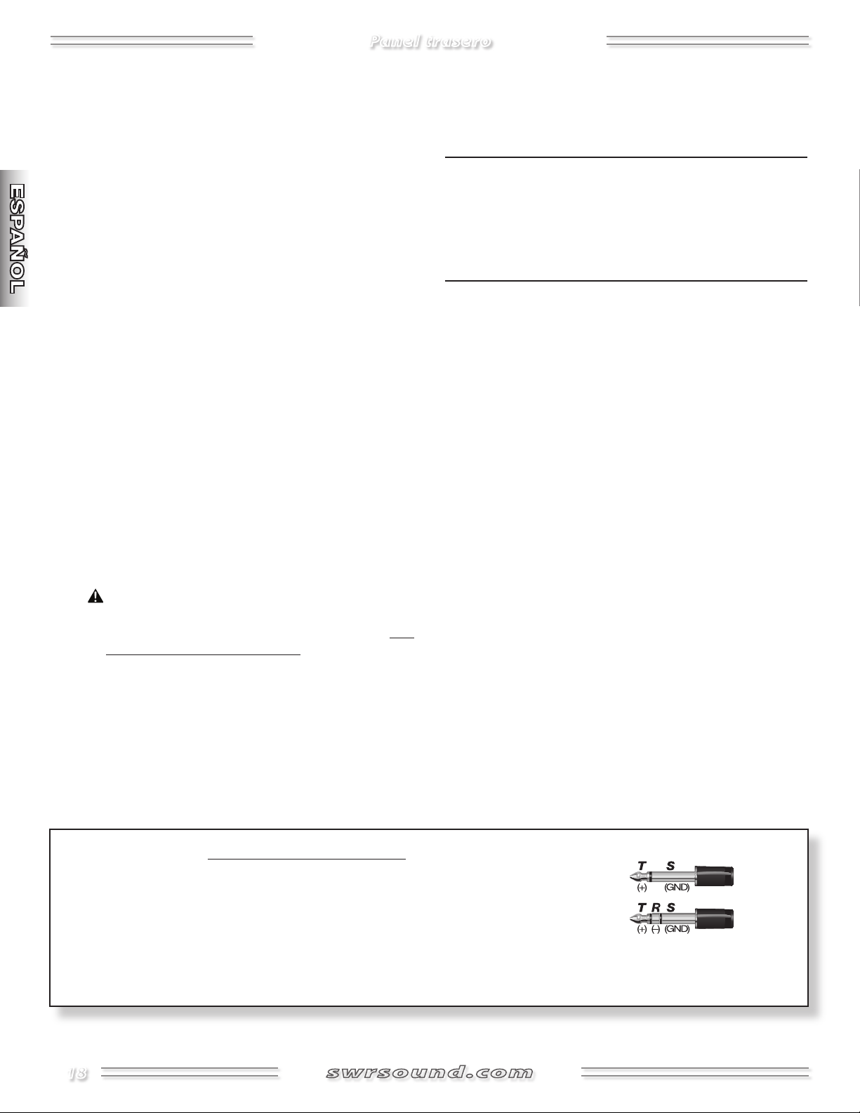
1
Conectores TRS balanceados
NOTA: Las tomas {FF, GG, JJ y KK} son del tipo TRS (Punta/Anillo/Lateral) balanceado y han
sido diseñadas para aceptar conectores tanto TRS como TS (Punta/Lateral):
Punta=positivo (+)
Anillo=negativo (–) y
Lateral=toma de tierra.
Aunque puede usar cables de guitarra TS "mono" standard, el uso de cables TRS "stereo" le permitirá mejorar la relación señal-ruido y/o
reducir los zumbidos, especialmente cuando necesite usar cables de grandes dimensiones.
18
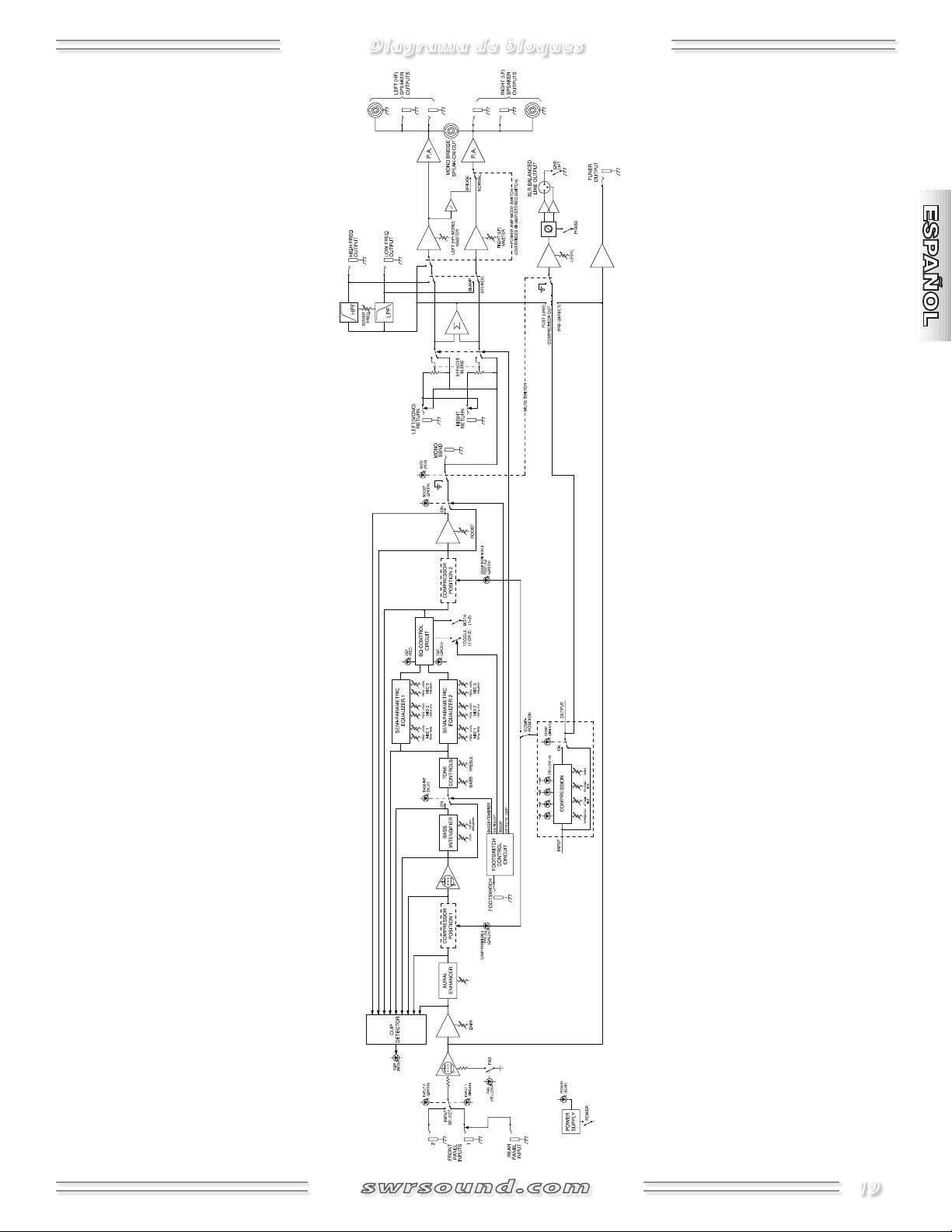
Diagrama de bloques
19
 Loading...