

SWRSound Professional Series User Manual

Professional Series and
Custom Pro Specialist Series
BASS SPEAKER ENCLOSURES
OWNER’S MANUAL
SWR • CORONA, CA • USA
PROFESSIONAL SERIES
GOLIATH III
GOLIATH JUNIOR III
GOLIATH SENIOR
MEGOLIATH
SON OF BERTHA
CUSTOM PRO SPECIALIST SERIES
BIG BEN
HENRY THE 8x8
TRIAD
12-PACK
12-STACK

Table Of Contents . . . . . . . . . . . . . . . . . . . . . . . . . . . . . . . . . . . . . . . . . . . . . . . . . . . . . . . . .1
General Information . . . . . . . . . . . . . . . . . . . . . . . . . . . . . . . . . . . . . . . . . . . . . . . . . . . . . . .2
Input Panel Diagrams . . . . . . . . . . . . . . . . . . . . . . . . . . . . . . . . . . . . . . . . . . . . . . . . . . . . . .3
Big Ben
1x18/tweeter cabinet . . . . . . . . . . . . . . . . . . . . . . . . . . . . . . . . . . . . . . . . . . . . . . . . .6
Henry The 8x8
8x8/tweeter cabinet . . . . . . . . . . . . . . . . . . . . . . . . . . . . . . . . . . . . . . . . . .7
Goliath III
4x10/tweeter cabinet – 4 and 8 ohm models . . . . . . . . . . . . . . . . . . . . . . . . . . . . . . .8
Goliath Junior III
2x10/tweeter cabinet – 4 and 8 ohm models . . . . . . . . . . . . . . . . . . . . . . .9
Goliath Senior
6x10/tweeter cabinet . . . . . . . . . . . . . . . . . . . . . . . . . . . . . . . . . . . . . . . .10
Megoliath
8x10/tweeter cabinet . . . . . . . . . . . . . . . . . . . . . . . . . . . . . . . . . . . . . . . . . . . . .11
Son Of Bertha
1x15/tweeter cabinet . . . . . . . . . . . . . . . . . . . . . . . . . . . . . . . . . . . . . . . .13
Triad
three-way speaker system . . . . . . . . . . . . . . . . . . . . . . . . . . . . . . . . . . . . . . . . . . . . . . . . .14
12-Pack
2x12 bass cabinet . . . . . . . . . . . . . . . . . . . . . . . . . . . . . . . . . . . . . . . . . . . . . . . . . .15
12-Stack
4x12 bass cabinet . . . . . . . . . . . . . . . . . . . . . . . . . . . . . . . . . . . . . . . . . . . . . . . . .16
Impedance: A General Overview . . . . . . . . . . . . . . . . . . . . . . . . . . . . . . . . . . . . . . . . . . .17
Troubleshooting Guide . . . . . . . . . . . . . . . . . . . . . . . . . . . . . . . . . . . . . . . . . . . . . . . . . . .18
Safety Instructions . . . . . . . . . . . . . . . . . . . . . . . . . . . . . . . . . . . . . . . . . . . . . . . . . . . . . . .20
Warranty Information . . . . . . . . . . . . . . . . . . . . . . . . . . . . . . . . . . . . . . . . . . . . . . . . . . . . .21
TABLE OF CONTENTS
BASS SPEAKER ENCLOSURES OWNER’S MANUAL • 1
INTRODUCTION
Congratulations on your purchase of an SWR Professional Series or Custom Pro Specialist Series bass speaker enclosure.
By placing an SWR cabinet in your bass amplification system you have made a sound desicion that could very well be the
best of your life!
Just a little humor there, but true nonetheless. For over 15 years we here at SWR have been putting everything we know
about bass into our Professional Series and Custom Pro Specialist Series bass cabinets. We’ve earned a reputation for
designing and manufacturing gear that has changed the way bassists hear themselves. That’s why you’ll find our bass amps,
cabinets, and combos on stages and in recording studios all over the world, and why you’ll hear SWR on countless recordings, spanning all genres of music.
Inside this Owner’s Manual you’ll find specifications, features, and usage suggestions for every Professional Series and
Custom Pro Specialist Series bass enclosure we make. New SWR user and seasoned user alike will benefit from reading
through this brief but informative manual. You can learn all about your current cabinet AND check out your SWR extension
options, too.
Thanks for making SWR a part of your bass amplification system.
Sincerely,
SWR

GENERAL INFORMATION
CONNECTION
Only one amplifier at a time can be connected to your SWR speaker enclosure. DO NOT plug two amplifiers into one speaker
enclosure, as it will not work and may damage your system. Always complete your amplifier-to-speaker and speaker-to-speaker connections before powering up your system.
SPEAKER CABLE
Only SPEAKER CABLE of 18 gauge or heavier (the heavier the cable, the lower the gauge) should be used to connect your amplifier to your SWR speaker enclosure. Do not use shielded instrument cable to connect your amplifier to your speakers, as this can
result in intermittent power loss, cause your amp to oscillate and damage itself and/or your speakers, and render the cable useless for any purpose.
SPEAKON JACKS
Whenever possible, use of the Speakonjacks is recommended. Speakon jacks and connectors offer the best possible connection and are far superior to banana or 1/4" phone jacks in that they not only lock in place (preventing accidental disconnection), but also offer a greater and more stable connection surface. This solid connection provides a more effective transfer
of power to your speakers, particularly from high-powered amplifiers.
TWEETER PROTECTION CIRCUIT
The tweeter protection circuit for SWR Professional Series speaker enclosures includes a size 3AG, 3 amp, 250 volt, fast-blo
fuse. Do not replace this with a fuse of a higher rating as it will void your warranty. A sudden burst of feedback or a heavily
clipped waveform can cause the fuse to open, resulting in loss of output from the tweeter.
SHOCK MOUNTED STEEL GRILL
The custom-manufactured steel grill is mounted on the top and sides with hard rubber standoffs and is installed to protect
your SWR speaker enclosure’s components from puncture or other physical damage. The standoffs act as “shock absorbers”
when the grill is bumped, and are also intended to prevent the grill from rattling during use. Prior to shipping, the grill mounting
screws are tightened to a point where the standoff barely compresses. This keeps the height of the grill far enough off the
speaker and prevents the grill from rattling on the head of the screw. Should the screws loosen, some rattling may occur. If
this happens, simply tighten the screws until they become snug. Do not over-tighten the screws, as this could bring the grill
too close to your speaker(s) and cause interference with the speaker cone.
CLEANING AND MAINTENANCE
A soft, dry cloth can be used to remove smudges or fingerprints from the chrome grill. A stiff brush (such as those available in
the cleaning section of most supermarkets) can be used to keep the cabinet’s carpeting free of lint, pet hair and dust. Should
you encounter a problem with the carpet collecting odor (from smokey clubs, etc.) a common carpet cleaner can be used. It is
recommended that, prior to spraying down the entire covering, you test whichever cleaner you choose on a small, inconspicuous area on the underside of the enclosure. This will prevent any accidental discoloration from being in view. All screws on the
baffle and input panel should be checked periodically for tightness, so as not to become loose (causing rattles or air leaks) or
lost.
2 • BASS SPEAKER ENCLOSURES OWNER’S MANUAL
TILT-BACK DESIGN
SWR’s Megoliath, Goliath Senior and Henry The 8x8 feature a tilt-back design for easy transportation. To take advantage of
this feature, firmly grasp the bar or handle (depending on the model) found on the top rear surface of the enclosure. Carefully
pull the top of the cabinet toward you so that the enclosure balances on its heavy-duty caster wheels. When a comfortable
balance is achieved, push forward in the direction you want to move the enclosure.
REMOVABLE CASTER WHEELS – GOLIATH III AND 12-STACK MODELS
The Goliath III and the 12-Stack are shipped with a set of four, heavy-duty, removable caster wheels. SWR uses only closed shaft
sockets so as to prevent air leaks or unwanted noise when the enclosure is in use. To install the caster wheels on these speaker
cabinets, carefully turn the enclosure upside down (or on its side) so that the caster base/sockets are visible. Insert the shaft of
each caster wheel into a socket on the underside of the speaker cabinet. When all four wheels are firmly in place, return the cabinet to its upright position and you’re ready to roll. You can leave the casters in place during performance, but it’s recommended
that they be removed prior to setting up your amplification system. This will allow your cabinet to couple to the floor, which can
be helpful in extending your system’s bass response. Please note that the ball bearing type caster wheels provided with your
Goliath III or 12-Stack cabinet may require periodic replacement depending on usage and care. Replacement caster wheels can
be purchased from the SWR Service Department.
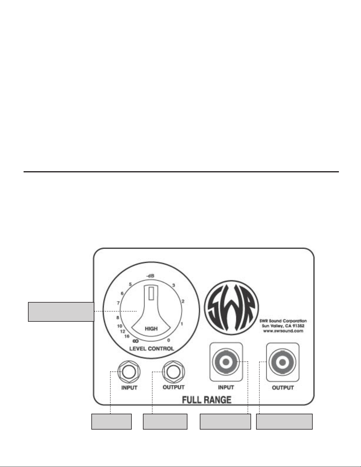
INPUT PANEL DIAGRAMS
All models (except Big Ben, 12-Pack, 12-Stack and Megoliath)
Tweeter Attenuator
Control
1/4" Input 1/4" Output
Speakon Input Speakon Output
BASS SPEAKER ENCLOSURES OWNER’S MANUAL • 3
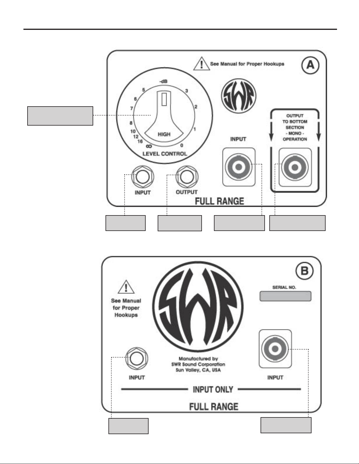
Panel A
(top chamber)
Tweeter Attenuator
Control
Panel B
(bottom chamber)
1/4" Input
1/4" Output
Speakon Input Speakon Output
1/4" Input
Speakon Input
INPUT PANEL DIAGRAMS
Megoliath
4 • BASS SPEAKER ENCLOSURES OWNER’S MANUAL
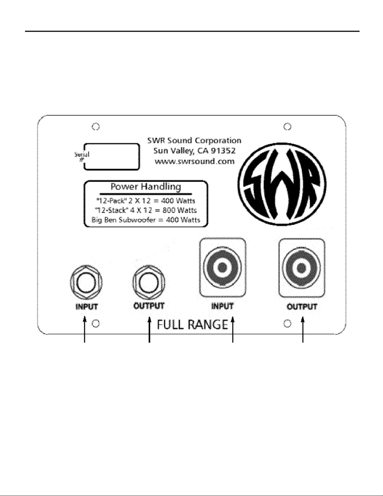
INPUT PANEL DIAGRAMS
Big Ben, 12-Pack, 12-Stack
1/4-inch connections
Input Output
Speakon connections
Input Output
BASS SPEAKER ENCLOSURES OWNER’S MANUAL • 5
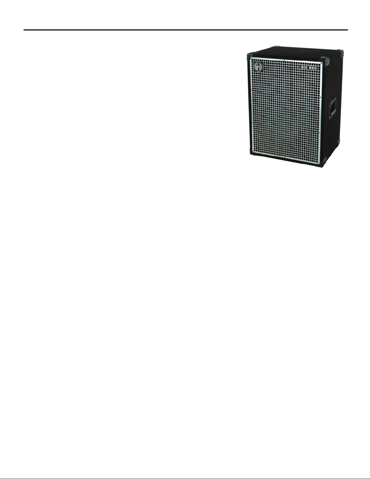
BIG BEN
SPECIFICATIONS
Power Handling: 400 watts RMS
Impedance: 8 Ohms
Frequency Response and SPL: 100 dB SPL @ 2W1M
(–6dB @ 25 Hz and 3 kHz)
Speaker Complement: (1) 18" Woofer
Spring Loaded Rubber Grip Handles, Rear Circular Ports
Dimensions: 23"W x 30.5"H x 18.5"D
Weight: 73 lbs.
DESCRIPTION
Big Ben is an extremely fast, 1x18 subwoofer. It can be used as a stand-alone
speaker enclosure, as part of a bi-amp system, or as the low end component for
any large, multi-speaker bass rig. It’s a must-have for any true bottom dweller.
CONNECTION AND OPERATION
Big Ben can be connected to any musical instrument amplifier that is capable of driving an 8 ohm load. To connect your amplifier to Big Ben, run a high quality speaker cable (18 gauge or heavier) from your amplifier’s speaker output to one of the designated speaker inputs (Speakon on 1/4”) on Big Ben’s input panel.
POWER HANDLING
The power output rating for any amplifier connected to Big Ben should not exceed the enclosure’s 400 watt RMS power handling capacity. Please be aware that exceeding Big Ben’s power handling capacity can void the SWR warranty if any damage
occurs to the 18" woofer due to overpowering.
FULL RANGE INPUT AND OUTPUT JACKS
Big Ben features four, full range input/output jacks (two standard 1/4" and two Speakon) wired in parallel. If you are running
two speaker enclosures in parallel, connect the speaker cable from your amplifier to either jack labeled “IN,” and a second
speaker cable from either jack labeled “OUT” to the input of the second speaker enclosure.
6 • BASS SPEAKER ENCLOSURES OWNER’S MANUAL
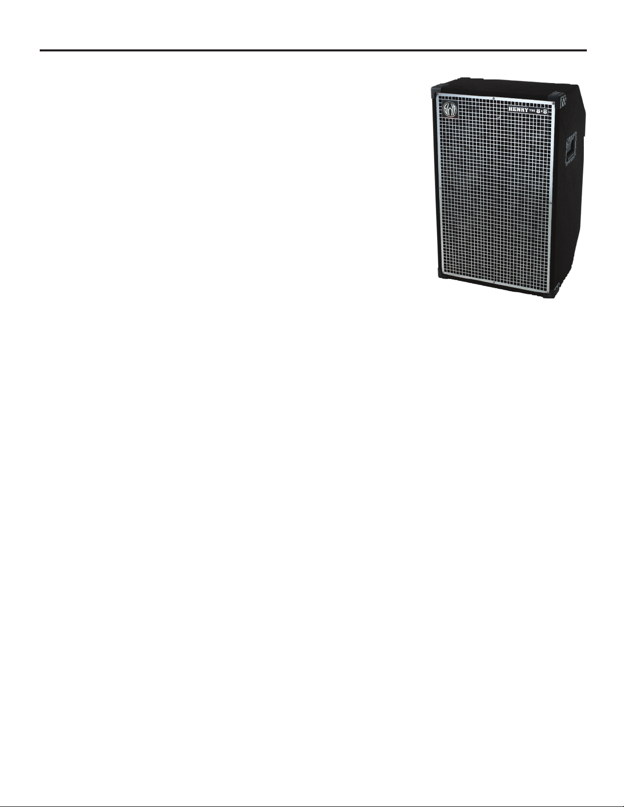
HENRY THE 8x8
SPECIFICATIONS
Description: 8x8 + Tweeter Speaker Enclosure
Power Handling: 480 watts RMS
Impedance: 4 ohms
Frequency Response & SPL: 96 dB SPL @ 1W1M
(–6 db @ 35 Hz and 18 Khz)
Speaker Complement: (8) custom 8" SWR drivers,
(1) Le-Son piezo tweeter
Heavy-Duty Casters, Spring Loaded Rubber Grip Handles, 2 Front Tube Ports, Top
Handle and Tilt Back Design for easy transportation.
Dimensions: 23"W x 36.5"H x 18.5"D
Weight: 100 lbs.
CONNECTION AND OPERATION
Henry The 8x8 can be connected to any musical instrument amplifier capable of driving
a 4 ohm load. To connect your amplifier to Henry The 8X8, run a high quality speaker
cable (18 gauge or heavier) from your amplifier’s speaker output to one of the designated speaker inputs (Speakon or 1/4")
on Henry The 8x8’s input panel.
POWER HANDLING
The power output rating for any amplifier connected to Henry The 8X8 should not exceed the enclosure’s 480 watt RMS
power handling capacity. Please be aware that exceeding Henry The 8X8’s power handling capacity can void the SWR warranty if any damage occurs to your loudspeakers due to overpowering.
FULL RANGE INPUT AND OUTPUT JACKS
Henry The 8X8 features four, full range input/output jacks (two standard 1/4" and two Speakon) wired in parallel. If you are
running two speaker enclosures in parallel, connect the speaker cable from your amplifier to either jack labeled “IN,” and a
second speaker cable from either jack labeled “OUT” to the input of the second speaker enclosure.
TWEETER ATTENUATOR CONTROL
The large dial found on the input panel of the cabinet is the Tweeter Attenuator. This control is used to adjust the level of high
frequency signal present at the tweeter. A normal setting for this control is straight up or “twelve o’clock.” Turning the dial fully
counter-clockwise removes the tweeter from the circuit. As you turn the dial clockwise from this position, the high frequency
content is increased.
INTERNAL CROSSOVER
Henry The 8X8’s internal (passive) crossover divides the incoming signal into two frequency bands. The crossover point is 5
kHz (frequencies above 5 kHz are sent to the tweeter, frequencies below 5 kHz are sent to the 8" speakers).
BASS SPEAKER ENCLOSURES OWNER’S MANUAL • 7
 Loading...