

EN
SolidFlow
Monitoring of solids

Operating Instructions
2
CONTENTS Page
1. System Overview . . . . . . . . . . . . . . . . . . . . . . . . . . . . . . . . . . . . . . . . . . . . . . . . . . . . . . . . . . . . . . . . . . . . . . 3
2. Function . . . . . . . . . . . . . . . . . . . . . . . . . . . . . . . . . . . . . . . . . . . . . . . . . . . . . . . . . . . . . . . . . . . . . . . . . . 3
3. Safety . . . . . . . . . . . . . . . . . . . . . . . . . . . . . . . . . . . . . . . . . . . . . . . . . . . . . . . . . . .
. . . . . . . . . . . . . . . . . . . . 4
3.1 Regular Use . . . . . . . . . . . . . . . . . . . . . . . . . . . . . . . . . . . . . . . . . . . . . . . . . . . . . . . . . . . . . . . . . . . . . .
4
3.2 Identification of Dangers . . . . . . . . . . . . . . . . . . . . . . . . . . . . . . . . . . . . . . . . . . . . . . . . . . . . . . . . . . . . 4
3.3 Operational Safety . . . . . . . . . . . . . . . . . . . . . . . . . . . . . . . . . . . . . . . . . . . . . . . . . . . . . . . . . . . . . . . . . 4
3.4 Technical Progress . . . . . . . . . . . . . . . . . . . . . . . . . . . . . . . . . . . . . . . . . . . . . . . . . . . . . . . . . . . . . . . . . 4
4. Mounting and Installation . . . . . . . . . . . . . . . . . . . . . . . . . . . . . . . . . . . . . . . . . . . . . . . . . . . . . . . . . . . . . . 5
4.1 Delivery Range . . . . . . . . . . . . . . . . . . . . . . . . . . . . . . . . . . . . . . . . . . . . . . . . . . . . . . . . . . . . . . . . . . . . 5
4.2 Auxiliary . . . . . . . . . . . . . . . . . . . . . . . . . . . . . . . . . . . . . . . . . . . . . . . . . . . . . . . . . . . . . . . . . . . . . . . . . . 5
4.3 Mounting of the Sensor . . . . . . . . . . . . . . . . . . . . . . . . . . . . . . . . . . . . . . . . . . . . . . . . . . . . . . . . . . . . . 5
4.4 Mounting of the Evaluation Unit . . . . . . . . . . . . . . . . . . . . . . . . . . . . . . . . . . . . . . . . . . . . . . . . . . . . . . 8
4.5 Overview of the Optional Use of the C-Box . . . . . . . . . . . . . . . . . . . . . . . . . . . . . . . . . . . . . . . . . . . . 9
4.6 Use in Ex Hazard Array . . . . . . . . . . . . . . . . . . . . . . . . . . . . . . . . . . . . . . . . . . . . . . . . . . . . . . . . . . . . . 10
5. Electrical Connection . . . . . . . . . . . . . . . . . . . . . . . . . . . . . . . . . . . . . . . . . . . . . . . . . . . . . . . . . . . . . . . . . . 11
6. Commissioning . . . . . . . . . . . . . . . . . . . . . . . . . . . . . . . . . . . . . . . . . . . . . . . . . . . . . . . . . . . . . . . . . . . . . . . 12
7. Menu Structure of SolidFlow . . . . . . . . . . . . . . . . . . . . . . . . . . . . . . . . . . . . . . . . . . . . . . . . . . . . . . . . . . . 14
8. Menu Parameters . . . . . . . . . . . . . . . . . . . . . . . . . . . . . . . . . . . . . . . . . . . . . . . . . . . . . . . . . . . . . . . . . . . . . 16
9. Connection Examples . . . . . . . . . . . . . . . . . . . . . . . . . . . . . . . . . . . . . . . . . . . . . . . . . . . . . . . . . . . . . . . . . 25
9.1 Digital Input . . . . . . . . . . . . . . . . . . . . . . . . . . . . . . . . . . . . . . . . . . . . . . . . . . . . . . . . . . . . . . . . . . . . . . 25
9.2 Impulse Output . . . . . . . . . . . . . . . . . . . . . . . . . . . . . . . . . . . . . . . . . . . . . . . . . . . . . . . . . . . . . . . . . . . 25
10. Additional Information for the Use of FME 300 Unit with a C3-Box . . . . . . . . . . . . . . . . . . . . . . . . . 26
11. Maintenance . . . . . . . . . . . . . . . . . . . . . . . . . . . . . . . . . . . . . . . . . . . . . . . . . . . . . . . . . . . . . . . . . . . . . . . . . 28
12. Warranty . . . . . . . . . . . . . . . . . . . . . . . . . . . . . . . . . . . . . . . . . . . . . . . . . . . . . . . . . . . . . . . . . . . . . . . . . . . . 28
13. Trouble Shooting . . . . . . . . . . . . . . . . . . . . . . . . . . . . . . . . . . . . . . . . . . . . . . . . . . . . . . . . . . . . . . . . . . . . . 28
14. Technical Data . . . . . . . . . . . . . . . . . . . . . . . . . . . . . . . . . . . . . . . . . . . . . . . . . . . . . . . . . . . . . . . . . . . . . . . 29
15. Quick Start Guide. . . . . . . . . . . . . . . . . . . . . . . . . . . . . . . . . . . . . . . . . . . . . . . . . . . . . . . . . . . . . . . . . . . . . 30
Operating Instructions
3
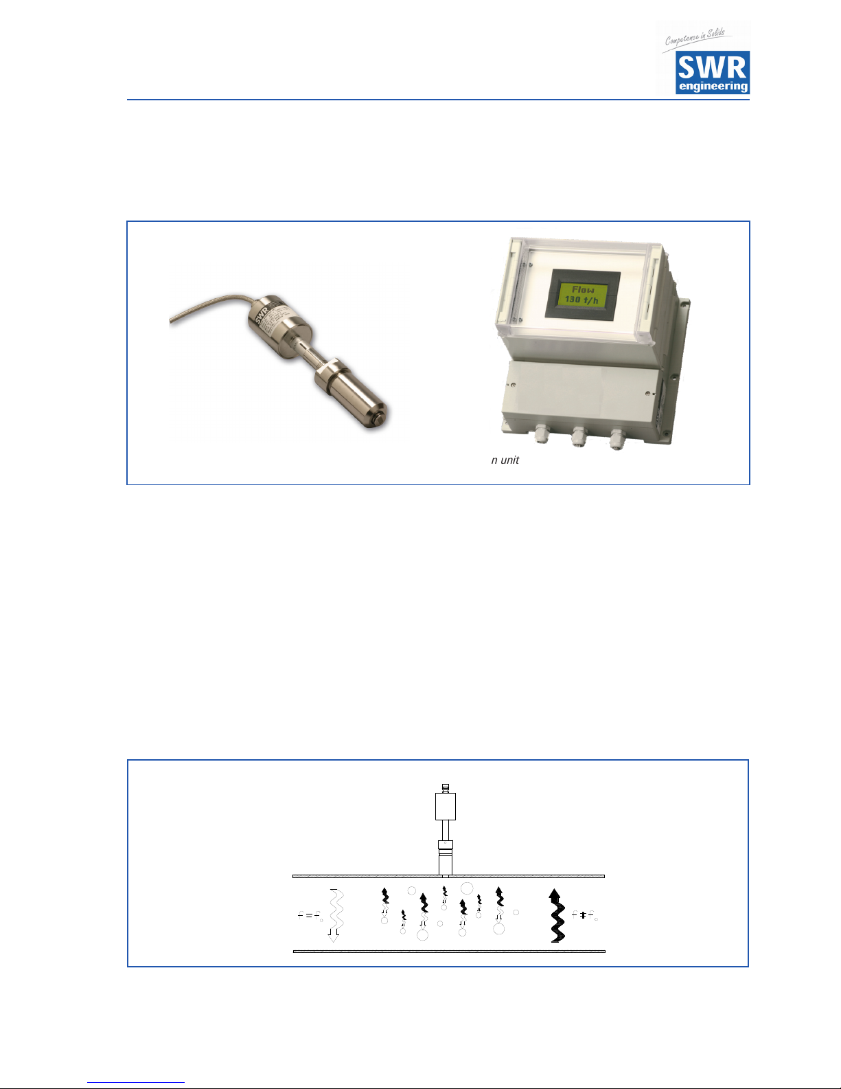
Sensor
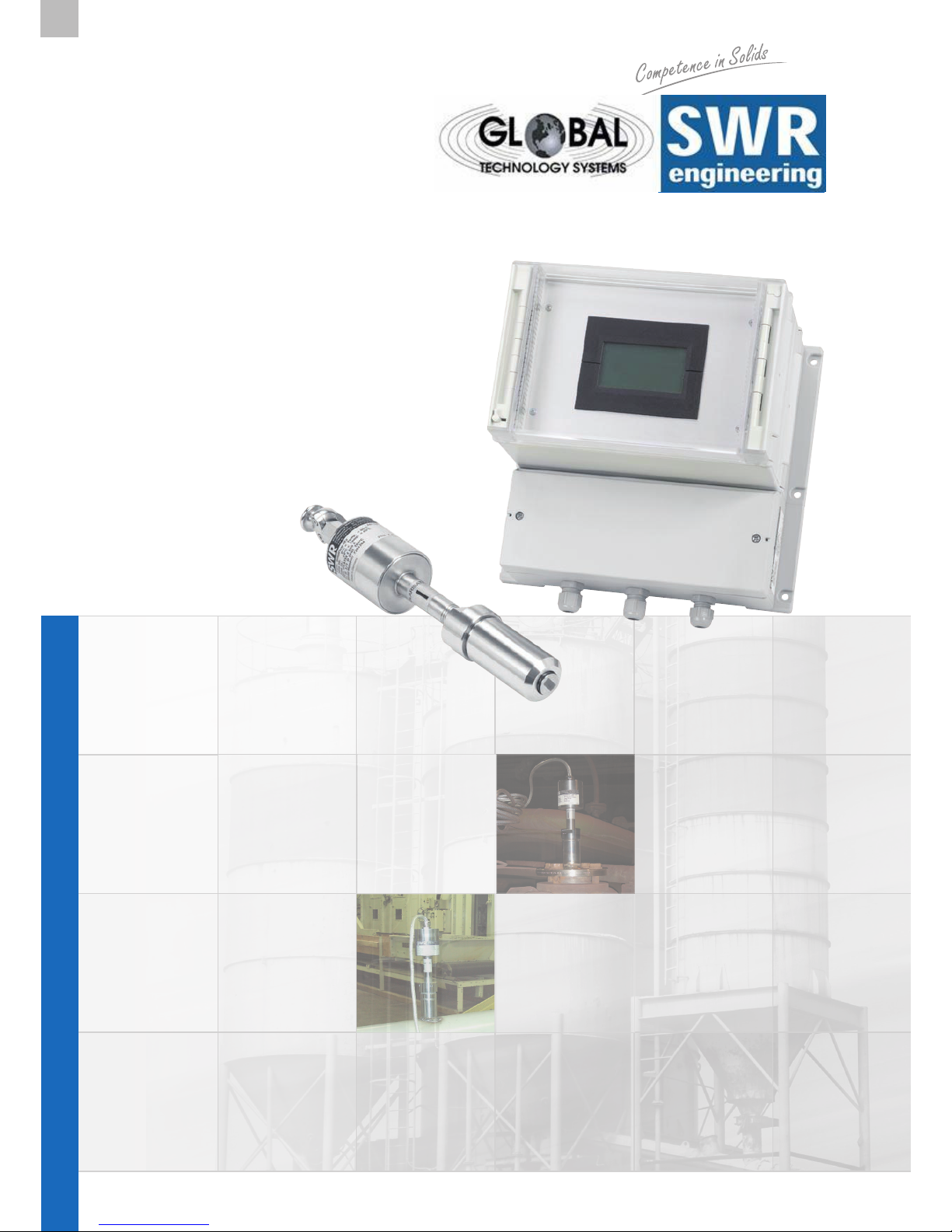
1. System Overview
Overview of the measuring system:
Fig. 3: Coupling and reflection of the microwaves.
and evaluation unit
2. Function
• SolidFlow is a measuring system especially developed for measuring the flow rate of conveyed solids in
metallic ducts.
• The SolidFlow sensor is based on the newest microwave technology. The sensor is usable in metal
ducts. Through the coupling of the microwave in the duct it is created a homogenous measured field.
• The microwave energy is being reflected by the solid particles and received by the sensor. These signals
are evaluated in frequency and amplitude.
• Because of the selective frequency evaluation only moving particles are measured.
• The measuring signal is independent of pressure and temperature in the duct. A measuring unit
consists of one sensor and the evaluation unit.
Operating Instructions
4
3. Safety
The measuring system SolidFlow was designed, built and tested to be safe and was shipped in safe conditions.
Nevertheless persons or objects may be endangered by components of the system if these are operated in an
inexpert manner. Therefore the operational instructions must be read completely and the safety notes must be
followed.
In case of inexpert or irregular use, the manufacturer will refuse any liability or guarantee.
3.1 Regular Use
• The measuring system must be installed for measuring the flow rate in metallic ducts only.
Other usage and modifications of the measuring system are not permitted.
• Only original spare parts and accessories of SWR engineering must be used.
3.2 Identification of Dangers
• Possible dangers when using the measuring system are marked by the following symbols in the
operating instructions:
Warning!
• This symbol in the operating instructions marks actions, which may represent a danger for life and limb
of persons when carried out in an inexpert manner.
Attention!
• All actions which may endanger objects are marked with this symbol in the operating instructions.
3.3 Operational Safety
• The measuring system must be installed by trained and authorised personnel only.
• Switch of the supply voltage for all maintenance, cleaning or inspection works on the tubes or on
components of the SolidFlow. Follow the notes of the chapter maintenance.
• Before hot-work the sensor must be removed from the piping.
• The components and electrical connections must be checked for damages regularly. If a damage is
found, it is to repaired before further operation of the instruments.
3.4 Technical Progress
• The manufacturer reserves the right to adapt technical data to the technical progress without particular
advance notice. If you have any questions, SWR engineering will be pleased to inform you on possible
changes and extensions of the operating instructions.
Operating Instructions
5
4. Mounting and Installation
4.1 Delivery Range
• Evaluation unit in the housing
• Weld on sensor accommodation
• Sensor (union nut, distance washers, seal-ring for adjustment)
• Operating instructions
• C-Box (optional)
4.2 Auxiliary
• Drill Ø 20 mm for steel
• 32 mm wrench for union nut
• Pliers for circlips (Ø 20 mm) for adjusting the wall thickness at the sensor
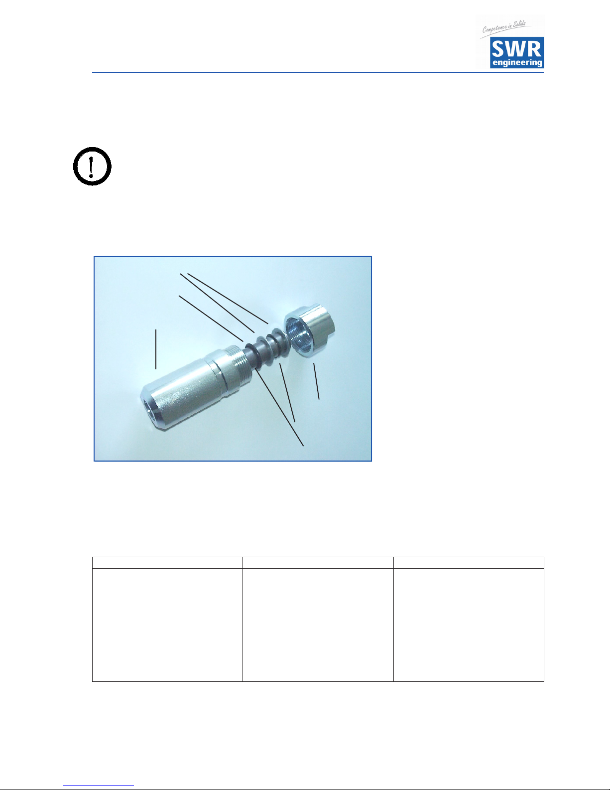
4.3 Mounting of the Sensor
The sensor is to be mounted as follows:
• Determine the place of mounting on the duct. On horizontal or inclined ducts the sensor should be
mounted from top.
• In case of duct diameters greater than Ø 200 mm or a special application one has to install up to three
sensors which are located 120 mm apart from each other and moved by 120° towards each other.
• The distances are valid for the vertical and horizontal installation position.
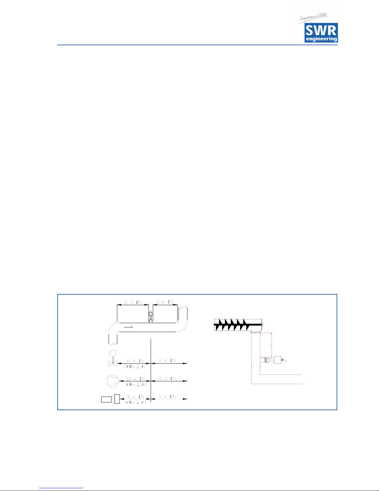
• Follow the necessary distances of valves, bows, fans or cellular wheel sluices etc. and also other
measurement devices like temperature and pressure etc. to the sensor. (see fig. 4)
Fig 4: Minimal distances of the sensor to duct bends and baffles.
• With free fall applications (e. g. after screw feeders or rotary valves) a free fall height of at least 300 mm
would be perfect.
Operating Instructions
6
• Weld the sensor accommodation on to the duct.
• Drill the Ø 20 mm hole into the duct. Please use your own drill as there are different shafts available.
Take care that the hole is in line and rectangular to the surface to avoid trouble by inserting the sensor.
Warning!
• After drilling you have to check, if there is a burr resulted at the drilling walls from the drilling. If so, this
burr in the duct must be removed with an appropriate tool. If this burr is not removed, a calibration of
the sensor is not possible!
• If the sensor is not installed immediately, the dummy plug must be put in until the sensor will be
installed (see fig. 5). Use a 32 mm wrench for tightening the union nut.
Fig. 5: Installation of the sensor
accommodation and the dummy plug.
Distance washer 1 mm
O-ring-type sealing
ring 36 x 3
Sensor accommodation
Union nut
Circlips for shafts
Dummy plug
q
q
q
q
q
q
q
• Fig. 5: Installation of the sensor accommodation and the dummy plug.
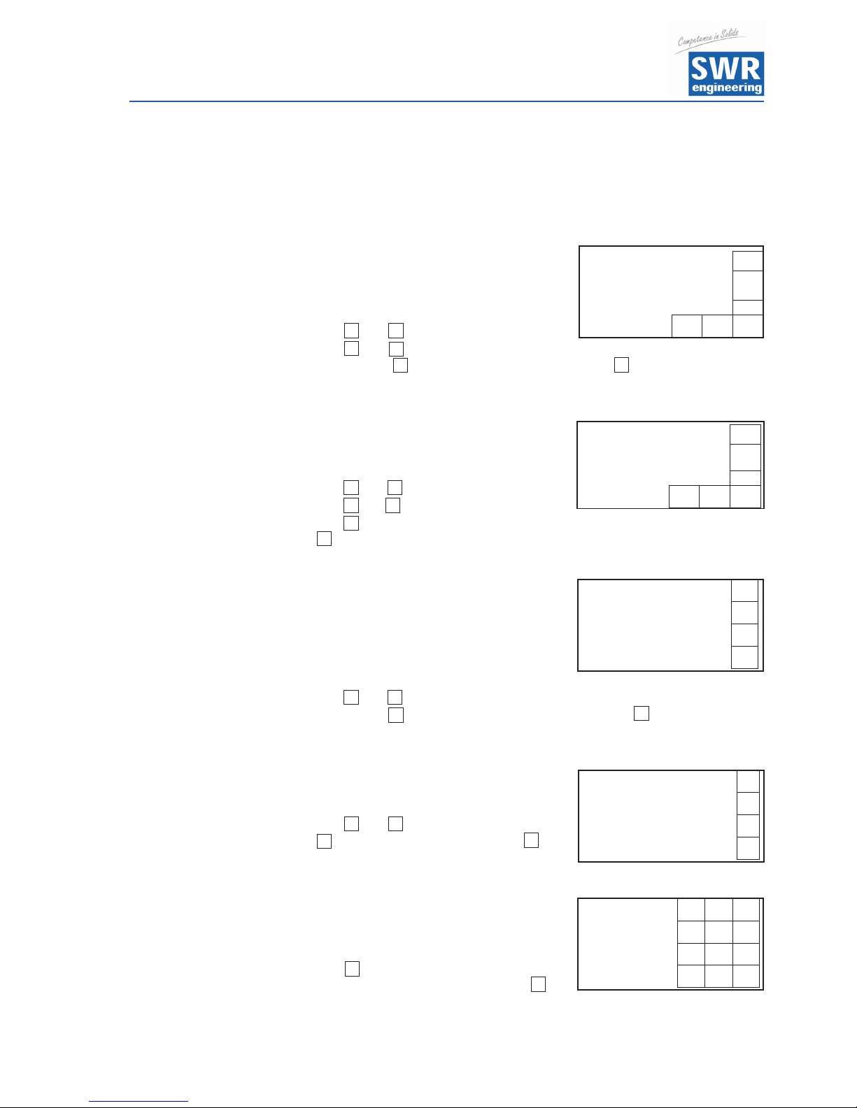
• It’s important that the sensor does not intrude into the duct because otherwise the front end of the
sensor will be worn by abrasion. If necessary the wall thickness must be checked with a depth gauge.
Then position the circlip in the complying slot. The sensor may be submerged into the duct wall by up to
1 mm without creating an error of measurement.
Wall thickness (mm) Circlip for shafts position Number of distance washers
3,0
4,0
5,5
6,5
8,0
9,0
10,5
11,5
13,0
14,0
1
1
2
2
3
3
4
4
5
5
2
1
2
1
2
1
2
1
2
1
• Now the sensor is put into the sensor accommodation and screwed with the union nut according to
figure 6a.
Operating Instructions
7
• Look at the POLARIZATION - label to adjust the sensor along to the duct, fig. 6b.
Fig. 6a: Installation of
sensor accommodation
and sensor.
Sensor accommodation
O-ring-type sealing ring 36 x 3
Distance washer 1 mm
Circlip for shafts 20 x 1.2
Distance washer 1 mm
Union nut
Sensor
q
q
q
q
q
q
q
1
2
• Lock the sensor with the union nut dust proof and fix the sensor.
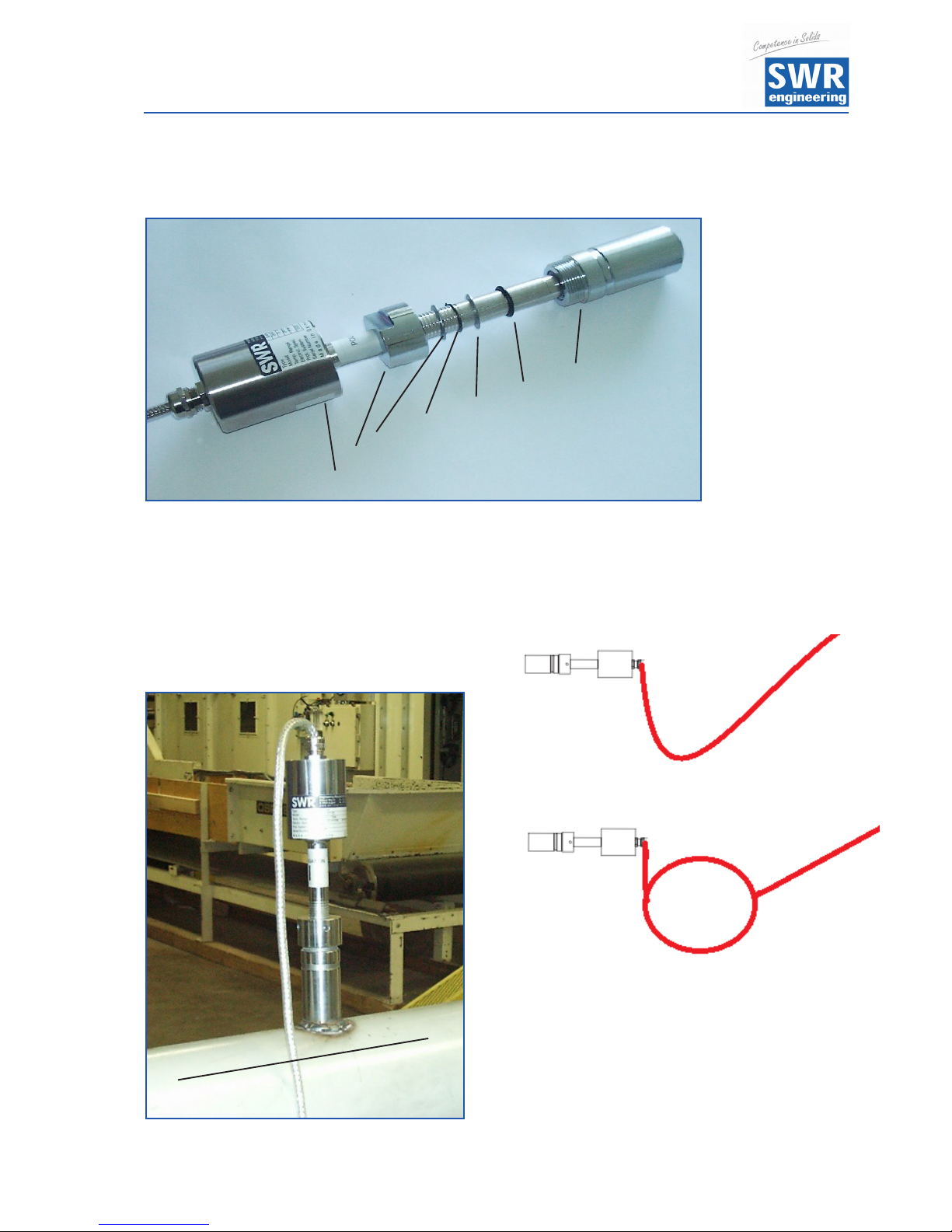
Fig. 6b: Adjustment of the sensor.
▼
Flow direction
• Make sure you install a drip loop with the cable anywhere it may get wet to prevent
water flow from reaching the sensor.

Operating Instructions
8
Fig. 7: Field housing evaluation unit.
Fig. 8: Field housing C-Box (optional).
4.4 Mounting of the Evaluation Unit
• The whole electronic equipment can be installed at a maximum distance of 300 m from the sensor.
The housing is prepared for wall mounting.
90
120
244
254
237
Sensor Evaluation Unit
PG11
98
86
36
64
Operating Instructions
9
The C-Box is an useful optional extension, if the distance between the sensor and the evaluation unit exceeds
the given standard length of 2 meters. The C-Box contains additional safety devices and terminal resistors to
guarantee the communication over the ModBus between the sensor and the evaluation unit even over longer
distances.
Sensor
C-Box Evaluation Unit
2 m cable
of the sensor
manufactures firmly
up to 300 m,
at sufficient conductor
cross section
4.5 Overview of the Optional Use of the C-Box

Operating Instructions
10
4.6 Use in Ex Hazard Array
Marking DustEx: II 1/2D Ex tD IP 65 T84 °C
Zone 20: 0 °C _< Tprozess _< 80 °C
Zone 21: -10 °C _< Tamb _< 60 °C
- Group of equipment 2
- Equipment category: 1/2
Waveguide window zone 20 / Housing zone 21
- For combustible mixtures from air and inflammable type of dust
- IP-Code 65
- Maximum surface temperature 84 °C with Ta = 60 °C
Marking GasEx: II 1/2D Ex tD A20/21 IP 65 T84 °C
II 2G Ex d IIC T5/T3
- Group of equipment 2
- Equipment category: 2
- Zone 1
- For combustible mixtures from air and inflammable type of gas
- IP-Code 65
- Allowable process temperature 0 to 150 °C
- Class of temperature T3
- Maximum surface temperature 84 °C with Ta = 60 °C
Ex hazard array
DustEx zone 20
GasEx zone 1
Zone 21/22
Zone 1/2
No ex hazard array
Tmax = 60 °C
Tmax =
150 °C
Operating Instructions
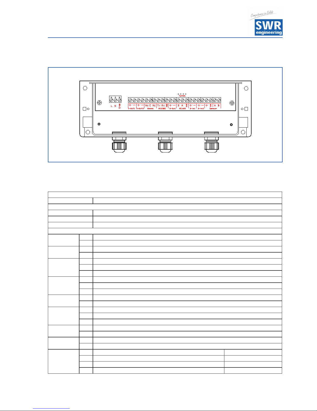
11
Evaluation Unit
Terminal No. Connection
Connection of the Supply Voltage
L / + 24 V Input Supply Voltage 230 V / 50 Hz, 110 V / 60 Hz (optional 24 V DC)
N / 0 V Input Supply Voltage 230 V / 50 Hz, 110 V / 60 Hz (optional 24 V DC)
PE Protected Earth
Sensor Connection
I-out
+ Analogue Output +
- Analogue Output -
NA not available
NA not available
Min. /
Max.Relay
NO Potential-free Relay NO (Close)
C Potential-free Relay COM (Common Conductor)
NC Potential-free Relay NC (Open)
RS 232
RX RS 232 Intersection Data
TX RS 232 Intersection Data
GND RS 232 Intersection Ground
D-out
+ Digital Output +
- Digital Output -
RS 485
B RS 485 Intersection Data B
A RS 485 Intersection Data A
GND RS 485 Intersection Ground
D-in1
+ Digital Intersection 1 (+)
- Digital Intersection 1 (-)
D-in2
+ Digital Intersection 2 (+)
- Digital Intersection 2 (-)
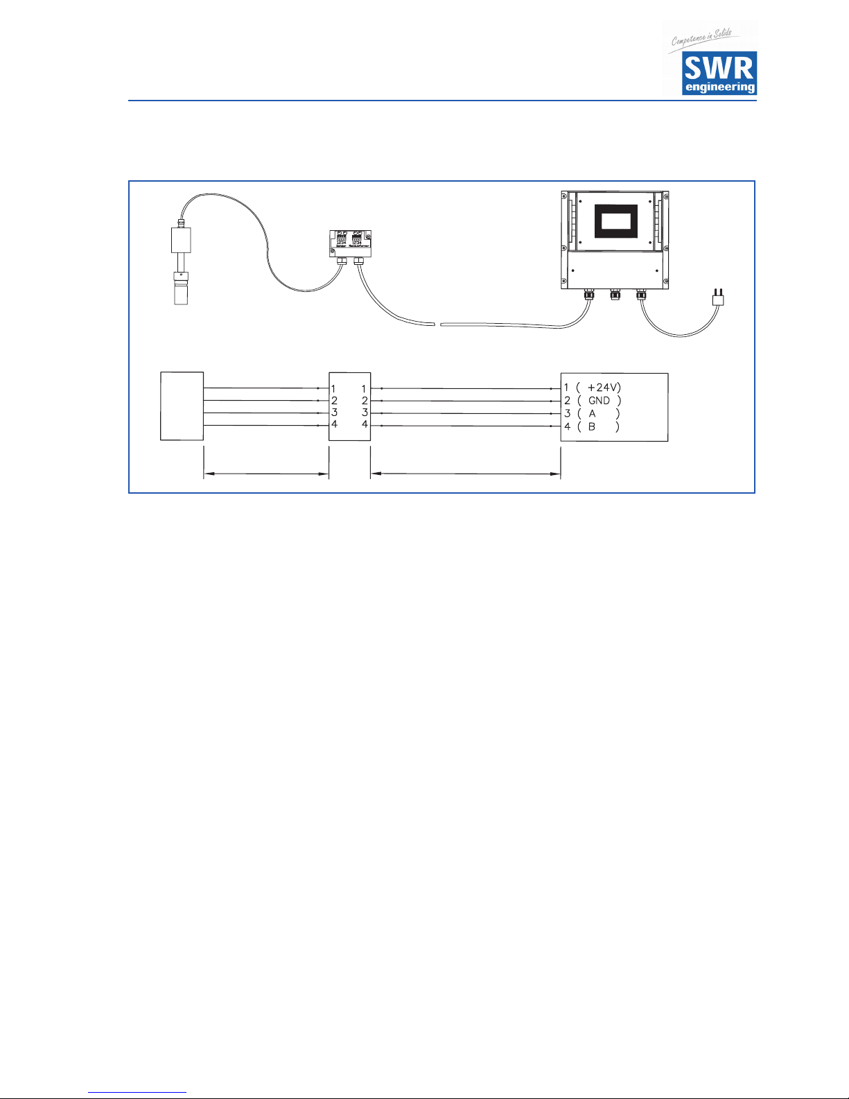
Sensor
+ Supply Voltage 24 V (+) Cable No. 1
- Supply Voltage 24 V (-) Cable No. 2
A RS 485 Data A Cable No. 3
B RS 485 Data B Cable No. 4
5. Electrical Connection
Fig. 9: Electrical connection

Operating Instructions
12
6. Commissioning
• For start-up the measurement system it is necessary to adjust the sensor to the local conditions. After
switching on the power supply there is at least a warm-up time about 15 minutes required before any
adjustment starts.
Please check again:
• The correct cabling between sensor and the evaluation unit.
• The correct adjustment of the wall thickness at the sensor.
• In case that despite these steps a successful measurement is impossible, please contact SWR.
Commissioning of SolidFlow
For start-up the sensor has to be calibrated and parameterized to each product, which will be
measured. It is necessary to assign the mass flow to the display and initial value. The menu functions
are mostly self-explaining. Following a short introduction to the overview:
By leaving the menu level and confirming the memory function in menu 8 all values changed are
transferred.
Starting The menu is started by an invisible key in the upper right corner of the
the Menu touch-screen-panel. Now press approx. 5 seconds until the menu
appears. If the temperature indication is activated, the button for the
temperature indication is in the upper right corner, in this case must be changed
into the temperature indication first, in order to be able to access the menu.
Basic Function It is sufficient to carry out a two-point-calibration (normally min and max).
Enter the data in menu 4.2.
Current / The initial values are defined in the menu points 1.5 and 1.6.
Voltage- The output value (current / voltage) is assigned to the measuring range here.
Output Standard 0 = 4 mA
Max = 20 mA
The measuring range filter is used for the adjustment to slower working devices
or for a continuous output of the analog output.
Min-Point Set point 1 to 0, with no material flow but system running.
Max-Point Set point 2 to known maximum flow rate with normal conveying and calibrate as
well. (This value can be adjusted later on.)
Thus the basic function of the measuring system is given and it is now ready for
operation.
Adjustment See menu 1, point 1 to 3 for the adjustments to the individual local conditions
regarding material, measuring units, etc.

Operating Instructions
13
Alarms entered by the user in menu 2.
Analog Output is modified in menu 3 and can be adjusted to the individual requirements.
(e. g. 0 - 20 mA)
Auxiliary Points The linearisation can be examined by measuring the varying mass throughput.
This should be weighed out in each single case for the improvement of the
accuracy. If there are deviations the non-linearity can be corrected by a basic
table. According to the chosen and fixed points in menu 4.2 (minimum 2 for the
first start-up of the commissioning), it is now possible to enter a correction value
for the actual mass flow. (This value can be changed afterwards.)
Pulse Output The pulse output can be parameterized to the value displayed in point 5 of the
menu. This is done by declaring the number of pulses per mass unit e. g.:
the mass unit is set to 1 t! The pulse output is set on 10.0 impulse / unit.
So there will be one pulse every 100 kg.
Note: please make sure that the indicated pulses do not exceed 50 pulses per
second. After changing the pulse configuration you will have to do a total reset
of the evaluation unit by interrupting the power supply a few seconds.
Otherwise the changing wouldn’t be activated.
Digital Input All digital inputs may be used for a reset of the totalizer.
System Adjustment of the ModBus by entering the “baud rate” and address.
Correction of the contrast and the delay of the backlight for ergonomics.
Totalizer With the totalizer function it is possible to monitor the entire flow rate since the
last reset of the totalizer. A RESET can be accomplished over an external control
line (see digital input) or directly over the display by pressing the R-symbol.
Storage When leaving the system you will be asked, if adjusted values should be stored
or not. By pressing ok the adjustment is done, by pressing n it will be rejected.
C-Box Will only be used, if the distance between the sensor and the evaluation unit
exceeds 2 meters.

Operating Instructions
14
Following the menu parameters in detail:
7. Menu Structure of SolidFlow
1. Measuring Range
1.1 Tag No Adjust Material (10 Digits)
1.2 Unit Adjust Text e. g. kg
1.3 Time Scale Choose: h / min / s
1.4 Decimal Point Choose Position of Dec. Point
1.5 Beginning of Measuring Range Range 0 ... 999
1.6 End of Measuring Range Range 0 ... 999
1.7 Filter Value Range 0.1 ... 999.9 s
2. Alarm
2.1 Type of Alarm Choose: Min / Max
2.2 Value of Alarm -10 to 110 % in phys. Units
2.3 Alarm Dead Time Range 0.1 ... 99.9 s
2.4 Alarm Hysteresis 0.1 ... 99.9 %
2.5 Operation Mode
Choose: Working- / Static
Current Principle
2.6 Alarm Sensor Malfunction Choose: on / off
3. Analog Output
3.1 Beginning of Measuring Range Range: 0 ... 22 mA (Standard: 4 mA)
3.2 End of Measuring Range Range: 0 ... 22 mA (Standard: 20 mA)
3.3 MIN Point Range: 0 ... 22 mA (Standard: 3 mA)
3.4 MAX Point Range: 0 ... 22 mA (Standard: 20 mA)
3.5 Value of Alarm Range: 0 ... 22 mA (Standard: 3 mA)
3.6 Filter Time Range: 0.1 ... 99.9 s (Standard: 1 s)
3.7 Calibration: 4 mA
Adjust Current Output
(4 mA calibrated)
3.8 Calibration: 20 mA
Adjust Current Output
(20 mA calibrated)

Operating Instructions
15
4. Calibration
4.1 Calibration Factor Range 0.01 ... 9.99
4.2 Calibration Filter Range 0.1 ... 999.9 s
4.3 Number of Calibration Points Range 2 ... 20 Auxiliary Points
4.4 Calibration Range 0.1 ... 999.9 s
4.4.1 Calibration Point 1
Meas. Value
Range of Beginning End of Measuring Value
(in phys. Units)
4.4.2 Calibration Point 1 Raw Value Adjust Initial Value
. . . (depending on the no. of calibration points)
4.4.(2*N) Calibration Point N
Meas. Value
Range of Beginning End of Measuring Value
(in phys. Units)
4.4.(2*N+1) Calibration Point N Raw Value Adjust Initial Value
5. Impulse Output
5.1 Number of Impulses / Mass Unit Range 0.01 ... 99.9
6. Digital Input
6.1 Digital Input 1
6.1.1 Function
Choose:
None / Totalizer Reset
6.1.2 Direction of Action Choose: Current / Without Current
6.1.3 Filter Time Range: 0.1 ... 99.9 s
6.2 Digital Input 2
6.2.1 Function
Choose:
None / Totalizer Reset
6.2.2 Direction of Action Choose: Current / Without Current
6.2.3 Filter Time Range: 0.1 ... 99.9 s
7. System
7.1 Baudrate Choose: 4800 / 9600 / 19200 / 38400
7.2 ModBus-Address Range: 1 ... 255
7.3 Contrast Adjust Contrast
7.4 Language Choose: D / F / E
7.5 Backlight
Backlight Constant = 0
or Delay of Backlight in Minutes
Range 1 ... 99 min
7.6 Temperature Display Temperature Display On / Off
7.7 Total Counter Total Counter On / Off
Operating Instructions
16
8. Menu Parameters:
1. MEASURING RANGE
1.1 Tag No.
Freely selectable symbols
of the measuring medium - or place,
max. 10 digits.
With and select the letters or symbols
with and select place of the letter
(1 ... 10); with delete the respective letter and with transfer the entry and
leave the menu level.
1.2 Unit
Entry of the measuring range
max. 6 digits.
With and select the letters or symbols,
with and select the letter (1 ... 6),
with delete the respective letter and with
transfer the entry and leave the menu level.
1.3 Time Scale
Choose of the time unit is important for the
Totalizer - Choose h / min / s
/ s per second
/ min per minute
/ h per hour
With and select according to the
display, with leave the menu without any change, with transfer the entry
and leave the menu level.
1.4 Decimal Point
Adjust the digit in the display.
With and shift the comma.
is without function here and with
transfer the entry and leave the menu level.
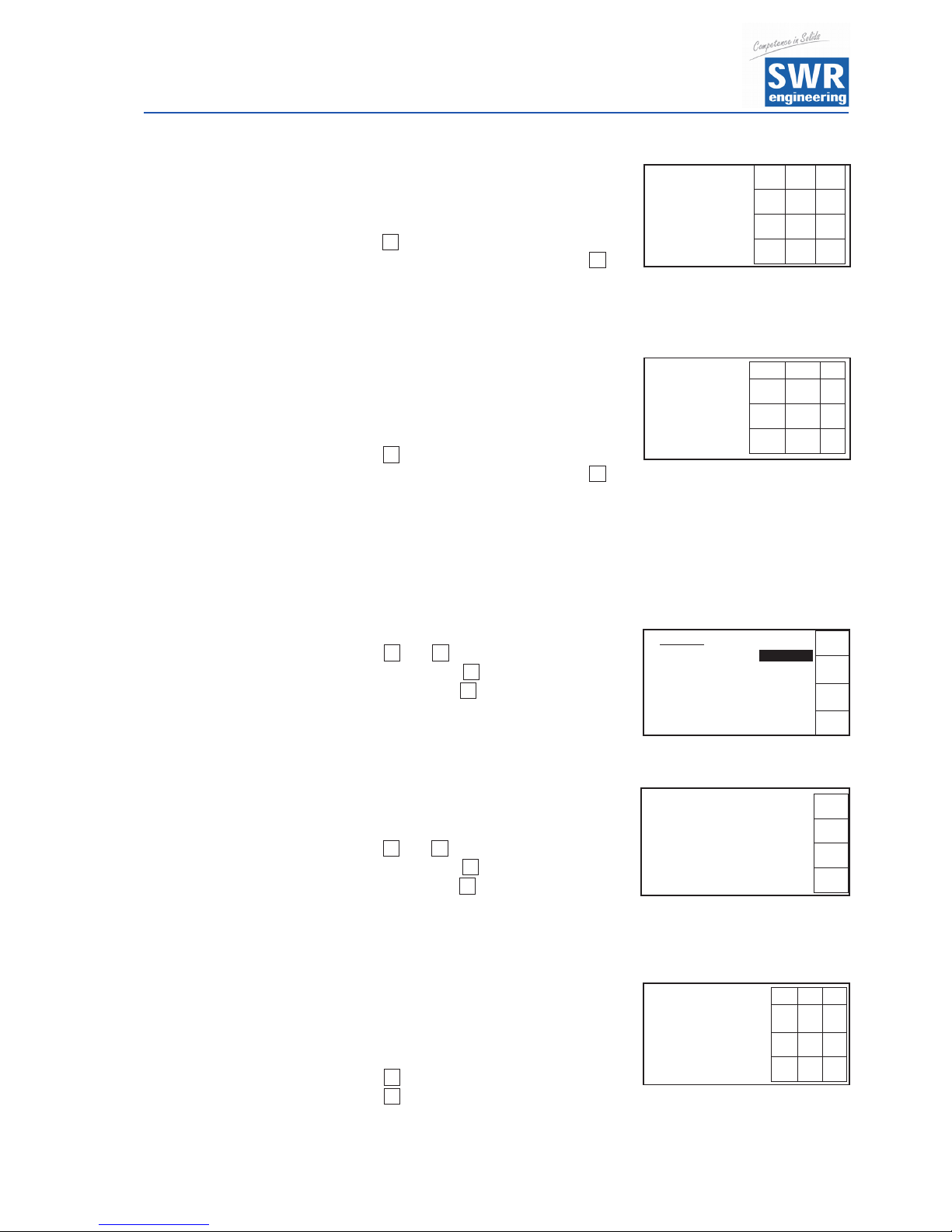
1.5 Beginning of Measuring Range
Enter the respective value of the measuring
range you will start with. Usually 0.0.
With set the value to 0.0 to start enter the
numbers of the measuring range, with
transfer the entry and leave the menu level.
¡
£
Meas. Range
£
Tag No.
¤
Material
C
¡ ¢
8
¤
¢
8
C
£
C
8
Meas. Range
£
Time Scale
¤
h
C
8
C
8
C
8
Meas. Range
£
Decimal Point
¤
000.0
C
8
¤
£ ¤
£ ¤
Meas. Range
£
Unit
¤
kg
C
¡ ¢
8
¢
¡
Meas. Range
7 8
9
Set low
4 5
6
0.0
kg/h
1 2 3
C
0
8
C
8
Operating Instructions
17
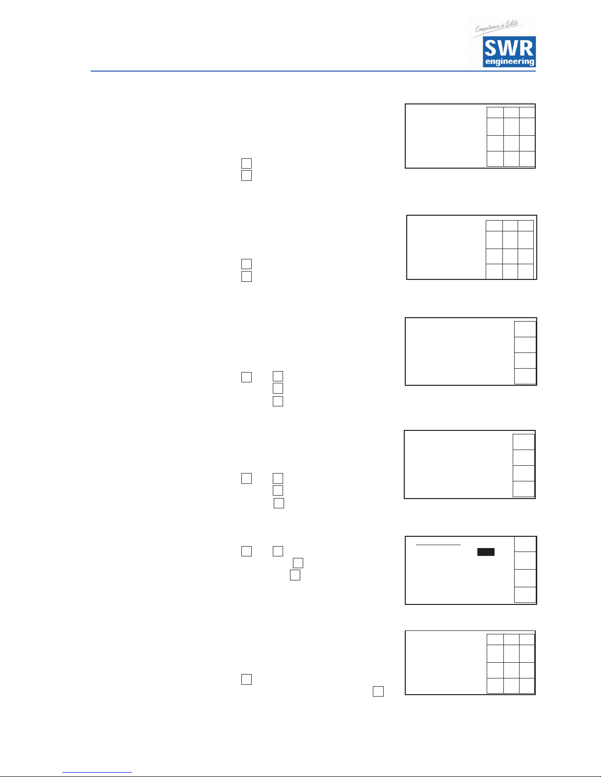
1.6 End of Measuring Range
Enter the respective value of the measuring
range end.
With set the value to 1.0 to start enter the
numbers of the measuring range, with
transfer the entry and leave the menu level.
1.7 Filter Value
Adjustable damping for the display in
seconds.
Range: 0.1 ... 999.9 s
With set the value to 0.0 to start enter the
numbers of the measuring range, with
transfer the entry and leave the menu level.
2. ALARM
Effect onto the relay
With and select according to your
significance, with leave the menu without
any change, with transfer the entry and
switch to a deeper menu level.
2.1 Type of Alarm
None / min / max.
With and select according to your
significance, with leave the menu without
any change, with transfer the entry and
switch to a deeper menu level.
2.2 Value of Alarm
Threshold value.
Range: -10 ... 110 % of the measuring range
in phys. units.
With leave the menu without any change,
with transfer the entry and leave the
menu level.
C
8
Meas. Range
7 8
9
Set high
4 5
6
10.0
kg/h
1 2 3
C
0
8
C
8
Meas. Range
7 8
9
Filter
4 5
6
1.0
s
1 2 3
C
0
8
C
8
C
8
£ ¤
Alarm 1
£
Alarm Type
¤
low alarm
C
8
C
8
£ ¤
Alarm
7 8 9
Alarm Value
4 5 6
1.0 kg/h
1 2 3
C
0
8
2. Alarm
£
2.1 Type low alarm
¤
2.2 Value 1.0
2.3 Delay 0.1 s
C
2.4 Hysteresis 1.0 %
8
q
Operating Instructions
18
2.3 Alarm Dead Time
Threshold value how long the value must be
over or under the limit until the alarm relay
reacts. Range
: 0.1 ... 99.9 s
With leave the menu without any change,
with transfer the entry and leave the
menu level.
2.4 Alarm Hysteresis
Threshold value of the alarm
Range
: 0.1 ... 99.9 % of the measuring range.
With leave the menu without any change,
with transfer the entry and leave the
menu level.
2.5 Operation Mode
Choice of the contact work or interruption.
NO - Working current
NC - Static current
With and select according to the
display, with leave the menu without any
change, with transfer the entry and leave the menu level.
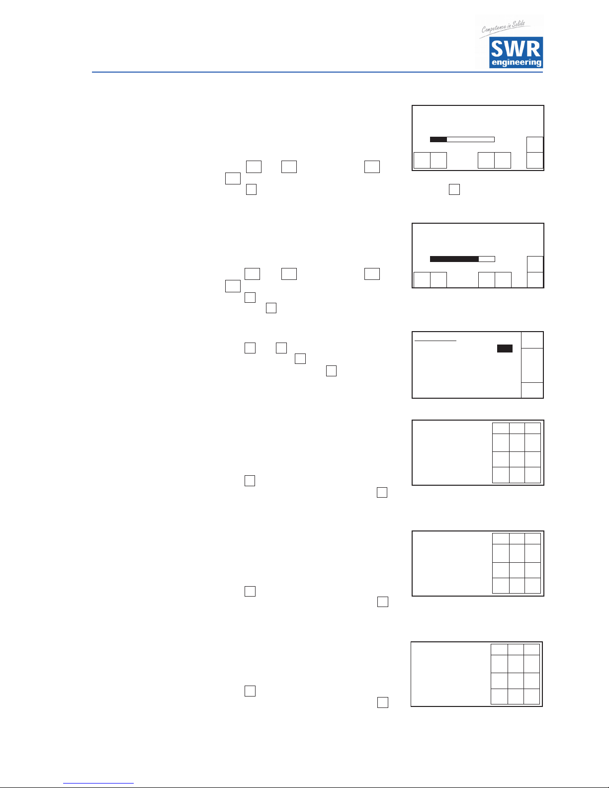
2.6 Alarm Sensor Error
Reaction by sensor error to the alarm and
current output. On / Off
With and select according to the
display, with leave the menu without any
change, with transfer the entry and leave
the menu level.
3. ANALOG OUTPUT
With and select according to your
significance, with leave the menu without
any change, with transfer the entry and
switch to a deeper menu level.
3.1 Starting Range
Value for the output min
(standard 4 mA) - Range 0 ... 22 mA
With set the value to 0.0 to start enter the
numbers of the measuring range, with
transfer the entry and leave the menu level.
C
8
8
C
Alarm
7 8 9
Hysteresis
4 5 6
1.0 %
1 2 3
C
0
8
Alarm
7 8 9
Delay
4 5 6
1.0 s
1 2 3
C
0
8
Alarm
£
Operation Mode
¤
NO
C
8
Analog Output
7 8 9
Range set low
4 5 6
4.0 mA
1 2 3
C
0
8
C
8
£
¤
Alarm
£
Sensor Fault
¤
on
C
8
C
8
£ ¤
C
8
£ ¤
C
8
3. Analog Out
£
3.1 set low 4.0 mA
¤
3.2 End 20.0 mA
3.3 Minimum 0.3 mA
C
3.4 Maximum 21.0 mA
8
q

Operating Instructions
19
3.2 End of Range
Value for the output max.
(Standard 20 mA)
Range 0 ... 22 mA
With set the value to 0.0 to start enter the
numbers of the measuring range, with
transfer the entry and leave the menu level.
3.3 MIN-Limit
Value for the MIN-Limit
Range 0 ... 22 mA
(Standard 3.0 mA)
With set the value to 0.0 to start enter the
numbers of the measuring range, with
transfer the entry and leave the menu level.
3.4 MAX-Limit
Value for the MAX-Limit
Range 0 ... 22 mA
(Standard 20 mA)
With set the value to 0.0 to start enter the
numbers of the measuring range, with
transfer the entry and leave the menu level.
3.5 Threshold Value
Value for alarm (Sensor error or internal
alarm) at the same time Rel 3 goes down.
Range 0 ... 22 mA
(Standard 3 mA)
With set the value to 0.0 to start enter the
numbers of the measuring range, with
transfer the entry and leave the menu level.
3.6 Filter Time
Adjustable damping for the current output.
Range 0.1 ... 999.9 s
(Standard 1 s)
With set the value to 0.0 to start enter the
numbers of the measuring range, with
transfer the entry and leave the menu level.
C
8
Analog Out
7 8 9
Lower-Limit
4 5 6
3.0 mA
1 2 3
C
0
8
Analog Out
7 8 9
Range set high
4 5 6
20.0 mA
1 2 3
C
0
8
C
8
C
8
C
8
C
8
Analog Out
7 8 9
Upper-Limit
4 5 6
20.0 mA
1 2 3
C
0
8
Analog Out
7 8 9
Threshold Value
4 5 6
3.0 mA
1 2 3
C
0
8
Analog Out
7 8 9
Filter Time
4 5 6
3.0 s
1 2 3
C
0
8
Operating Instructions
20
3.7 Trim 4 mA
Value of current min.
Adjust to the external measuring system
(if display differs).
With and adjust fast, with and
adjust slowly the current to 4 mA.
With transfer the entry and leave the menu level, with leave the menu
without any change.
3.8 Trim 20 mA
Value of current max. Adjust to the external
measuring system (if display differs).
With and adjust fast, with and
adjust slowly the current to 4 mA.
With transfer the entry and leave the menu
level, with leave the menu without any change.
4. Calibration
With and select according to your
significance, with leave the menu
without any change, with switch to
a deeper menu level.
4.1 Calibration Factor
Global calibration factor of the measuring
on the display and as well the output range
from 0.01 to 9.99 - Setting is 1.0
With set the value to 0.0 to start enter the
numbers of the measuring range, with
transfer the entry and leave the menu level.
4.2 Calibration Filter
Damping filter for setting unsteady signals
during the calibration.
(Has no effect on output and display)
0.1 to 999.9 s
With set the value to 0.0 to start enter the
numbers of the measuring range, with
transfer the entry and leave the menu level.
4.3 Number of
Calibration Points
Set the number of the auxiliary points:
2 ... 5 points.
With set the value to 0.0 to start enter the
numbers of the measuring range, with
transfer the entry and leave the menu level.
.
<<
8
C
Analog Out
Trim 4.0 mA
C
<< < > >>
8
>>
<
>
<<
8
C
>> <
>
Analog Out
Trim 20.0 mA
C
< < > >>
8
8
Calibration
7 8 9
Cal.-Factor
4 5 6
1.0
1 2 3
C
0
8
8
C
8
C
C
Calibration
7 8 9
Filter
4 5 6
1.0 s
1 2 3
C
0
8
Calibration
7 8 9
Segment Points
4 5 6
2
1 2 3
C
0
8
C
8
£ ¤
4. Calibration
£
4.1 Cal. Factor 1.0
¤
4.2 Filter 0.1 s
4.3 Aux. Points 2
C
4.4 Calibration
8
1.0
Operating Instructions
21
4.4 Calibration
With and select according to your
significance, with leave the menu
without any change, with transfer the
entry and switch to a deeper menu level.
4.4.1 Calibration Point 1 - Measuring Value
Measuring value in phys. units.
Range: Measuring start - Measuring end
With set the value to 0.0 to start enter the
numbers of the measuring range, with
transfer the entry and leave the menu level.
4.4.2 Calibration Point 1 - Raw Value
Indicate the initial value to the value
displayed, if pressed . With leave the
menu without any change.
All other points are calibrated as the first one.
4.4.3 Calibration Point 2 - Measuring Value
Measuring value in phys. units.
Range: Measuring start - Measuring end
4.4.4 Calibration Point 2 - Raw Value
Indicate the initial value to the value displayed.
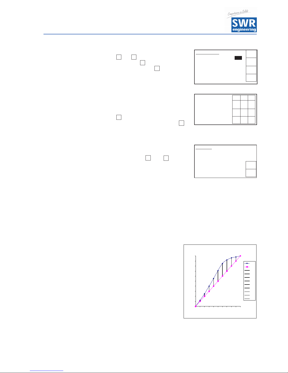
4.4.5 Calibration Point N - Measuring Value
Only necessary, if you are disturbed by
the non-linearity
(see diagram on the right side).
The measuring points of the nominal
characteristic curve will be typed in
and calibrated to the actual
characteristic curve. The customization
will be done by the evaluation unit.
The output values are linear.
Measuring value in phys. units.
Range:
Measuring start - Measuring end
4.4.6 Calibration Point N - Raw Value
Indicate the initial value to the value displayed.
C
8
C
8
£ ¤
8
C
Calibration
7 8 9
Calibration Point 1
4 5 6
0.0 kg/h
1 2 3
C
0
8
Calibration
Calibration Point 1
0.015663
C
Akt.: 0.015009
8
4.4 Calibration
£
4.4.1 Val. P1 1. 0.00
¤
4.4.2 Calibration P1
4.4.1 Val P2 1.58
C
4.4.2 Calibration P2
8
q
Stützpun ktke nnlinie
0
10
20
30
40
50
60
70
80
90
100
0 1 2 3 4 5 6 7 8 9 10
Messpunkte
Werte
ist
soll
Diff 1
Diff 2
Diff 3
Diff 4
Diff 5
Diff 6
Diff 7
Diff 8
Diff 9
Values
Set Points
Measuring Points
Operating Instructions
22
5. IMPULSE OUTPUT
(For connection examples see paragraph 9.2)
Only necessary, if impulse output is required.
With and select according to your
significance, with leave the menu without
any change, with transfer the entry and switch to a deeper menu level.
5.1 Number of Impulses / Units
Indicate the number of impulses requested
per mass unit. Range: 0.01 ... 99.9
With set the value to 0.0 to start enter the
numbers of the measuring range, with
transfer the entry and leave the menu level.
6. DIGITAL INPUT
Only necessary for a reset of the total
counter by an external device.
(For connection examples see paragraph 9.1)
With and select according to your
significance, with leave the menu
without any change, with transfer the
entry and switch to a deeper menu level.
6.1 Digital In 1
(For connection examples see paragraph 9.1)
With and select according to your
significance, with leave the menu
without any change, with transfer the
entry and switch to a deeper menu level.
6.1.1 Function
No function / external reset of totalizer
With and select according to the
display, with leave the menu
without any change, with transfer the
entry and leave the menu level.
6.1.2 Operating mode
Operation mode
Opened = direct
Closed = invert
With and select according to the
display, with leave the menu without
any change, with transfer the entry and leave the menu level.
C
8
£ ¤
8
C
C
8
£ ¤
Pulse out
7 8 9
Pulses / Units
4 5 6
10.00
1 2 3
C
0
8
£ ¤
C
8
£ ¤
C
8
Digital In 1
£
Function
¤
ResTot
C
8
Digital In 1
£
Norm. Open / Closed
¤
direct
C
8
£ ¤
C
8
5. Pulse out
£
5.1 Puls / Unit 10.00
¤
C
8
6. Digital In
£
6.1 Digital In 1
¤
6.2 Digital In 2
C
8
6.1 Digital In 1
£
6.1.1 Function ResTot
¤
6.1.2 NO / NC direct
6.1.3 Filter 1.0 s
C
8

Operating Instructions
23
6.2 Filter
Idle time after activation.
(Anti beat device for mechanical switches.)
With set the value to 0.0 to start enter the
numbers of the measuring range, with
transfer the entry and leave the menu level.
6.3 Digital In 2 like Digital In 1
7. SYSTEM
Adjusting of the ModBus intersection
parameter in case of a connection to the
system bus.
With and select according to your
significance, with leave the menu
without any change, with transfer the entry and leave the menu level.
7.1 Baud Rate
Indicating of the Baud rate
Choose: 4800 / 9600 / 19200 / 38400 Bd
With and select according to your
significance, with leave the menu
without any change, with transfer the
entry and leave the menu level.
7.2 ModBus Address
ModBus address in RTU-Mode (slave)
Selectable address 1 ... 255
With set the value to 0.0 to start enter the
numbers of the measuring range, with
transfer the entry and leave the menu level.
7.3 Contrast
Display contrast for a better legibility.
With and adjust fast, with and
adjust slowly to the contrast required,
with transfer the entry and leave the
menu level, with leave the menu without
any change.
7.4 Language
Indicating of the language - Choose: D / F / E
With and select according to your
significance, with leave the menu
without any change, with transfer the
entry and leave the menu level.
C
8
System
£
Baud Rate
¤
4800
C
8
8
C
Digital In 1
7 8
9
Filter
4 5
6
1.0 s
1 2 3
C
0
8
<<
>>
<
>
C
8
£ ¤
8
C
£ ¤
System
7 8
9
Address
4 5
6
1
1 2 3
C
0
8
8
C
System
£
Language
¤
E
C
8
8
C
£ ¤
7. System
£
7.1 Baud rate 9600 9600
¤
7.2 Address 1
7.3 Contrast
C
7.4 Language ENG
8
q
Contrast Setting
C
<<
< > >>
8
Operating Instructions
24
7.5 Backlight
Setting of durable lighting or the
luminescence intensity.
Zero switch on to permanent lighting.
With set the value to 0 (complies in this
menu to constant backlight) or enter the
numbers of minutes for the delay of the backlight, with transfer the entry
and leave the menu level.
7.6 Temperature Display
Switches display of internal
sensor temperature on / off.
The temperature is not available via
current output. This value do not
represent the temperature of product!
With and select according to your significance, with leave the menu
without any change, with transfer the entry and leave the menu level.
7.7 Total Counter
Switches the totalizer on / off.
With and select according to your
significance, with leave the menu
without any change, with transfer the
entry and leave the menu level.
8. Storage
Only with change and leaving the menu level.
With leave the menu without any change,
with transfer the entry and leave the
menu level.
C
8
System
£
Total Counter
¤
on
C
8
8
C
System
7 8
9
Backlight
4 5
6
0
min
1 2 3
C
0
8
£ ¤
8
C
£ ¤
System
£
Temperature Display
¤
off
C
8
ok
Store changes?
ok no
no

Operating Instructions
25
9. Connection Examples
9.1 Digital Input
▼
U
ST
9.2 Impulse Output
R = (Ub - 0.7 V)/l
RV = ((UST - 1.6 V) / 20 mA) - 2 kW
Open: 0 V
Closed: Ub - 0.7 V
Open: Ub
Closed: 0.7 V
Open Collector
Open Collector

Operating Instructions
26
10. Additional Information for the Use of a FME 300 Unit with a C3-Box
Connection
Evaluation UnitC3-Box
2 m
max. 300 m
Each sensor is recognized by its own address. The address is signed on the sensor rating plate.
Operating Instructions
27
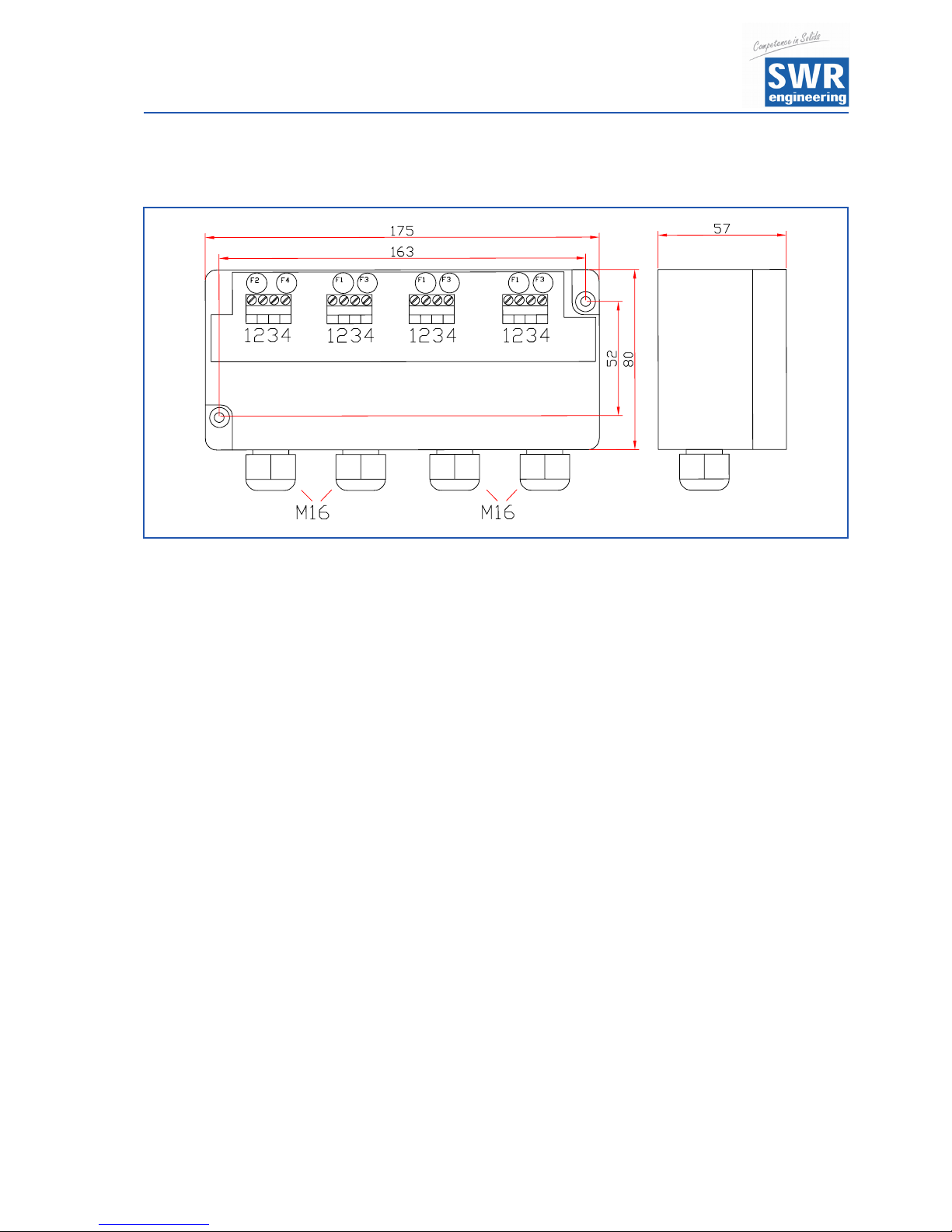
Connecting Diagram for C3-Box
Programming
In addition to the basic SolidFlow Start-up with one sensor it is necessary to switch on the sensors which should
be used for the measurement (normally all sensors which are installed). As well every sensor has his own
calibration-factor which can be used for adjusting the influence which each sensor gives to the measurement
result (normally factor 1.0 for all sensors).
This leads to the following menu-structure for the sensor calibration:
4.4 Calibration Sensor 1
4.4.1 Sensor on / Off
4.4.2 Calibration Factor Sensor
4.4.3 Calibration Point 1 Value
4.4.4 Calibration Point 1 Raw Value
4.4.5 Calibration Point 2 Value
4.4.6 Calibration Point 2 Raw Value
analogue for all further calibration points
4.5 Calibration Sensor 2
(like sensor 1)
4.6 Calibration Sensor 3
(like sensor 1)
The calibration of each sensor is to be done as it is described for the FME 100.
NOTE: It is important to program the total flow as a pre-set value for each sensor. The FME 300 is
calculating the average value of all single measurements automatically and this average value
will be given to the analog output.
Sensor 1
Sensor 2 Sensor 3
Evaluation Unit

Operating Instructions
28
11. Maintenance
Warning!
• Danger of shock with opened housing!
• Switch off the supply voltage for all maintenance or repair works on the measuring system. The tube
must not be in operation during a sensor exchange.
• Repair and maintenance work must be carried out by trained or expert personnel only.
• The system is maintenance-free.
12. Warranty
Warranty is granted for one year starting from delivery date under the condition that the operating instructions
have been followed, no interventions on the appliances have been made and the components of the system show
no mechanical damage or wear resistance.
In case of a defect during the warranty period, defective components are repaired or are replaced free of charge.
Replaced parts turn into the property of SWR. If desired by the costumer that the parts should be repaired or
replaced in its factory, then the costumer has to take over the costs for the SWR-service staff.
SWR is not responsible for damage, which did not develop at the delivery article; especially SWR is not responsible
for escaped profit or other financial damages of the customer.
13. Trouble Shooting
• Warning!
The electrical installation must only be checked by expert personnel.
Problem Cause Measure
Measuring system
does not work.
Power supply
interrupted.
Check the power supply.
Break of a cable. Check the connecting cables for a possible break of a cable.
Fuse defective. Exchange the fuse in the field housing.
Device defective. Please call SWR for further instructions.
Measuring system
outputs wrong values.
Calibration not correct. Delete input signal correction, new calibration according to
section 7.
Calibration shifted by
abrasion on front end of
sensor.
Delete input signal correction, new calibration according to
section 7.
Sensor error. Sensor not properly
connected.
Check cable.
Sensor damaged. Replace sensor.
No 24 Volt supply on
sensor.
Assure power supply.
Voltage drop on the supply
line too highly.
Examine cable lengths on the basis of the table in chapter 4.5
(page 9).
Relay output Relay flickering.
Hysteresis too small. Increase hysteresis, check effects caused by external devices.
Do not open, as otherwise the warranty claim expires!

Operating Instructions
29
14. Technical Data
Sensor / Sensor Accommodation
Housing: Steel St52, galvanised
(stainless steel 1.4541 option)
Protection category: IP 65, DustEx 20 or GasEx 1 (option)
Operating temperature: Front end of sensor: -20 ... + 80 °C [-4 ... 176 °F]
Optional:
-20 ... + 200 °C [-4 ... 392 °F]
Sensor electronic: 0 ... + 60 °C [32 ... 140 °F]
Max. working pressure: 1 bar, optional 10 bar
Working frequency: K-Band 24.125 GHz, ± 100 MHz
Transmitting power: Max. 5 mW
Weight: Approx. 1.3 kg
Dimension: Ø 60, Ø 20, L 290 mm
Accuracy: +/- 2 ... 5 % in calibrated range
Evaluation Unit
Supply voltage: 110 / 240 V AC 50/60 Hz (optional 24 V DC)
Power consumption: 20 W / 24 VA
Current consumption: Max. 1 A @ 24 V
Protection category: IP 65 to EN 60 529/10.91
Operating temperature: -10 ... +45 °C [14 ... 113 °F]
Enclosure dimensions: 225 x 237 x 174 (W x H x D)
Weight: Approx. 2.5 kg
Additional data:
Cable glands: 3 x M16 (4.5 - 10 mm Ø)
Screw terminals: 0.2 – 2.5 mm² [AWG 24-14]
Current output signal: 4 ... 20 mA (0 ... 20 mA), load < 700 W
Measurement value alarm relay output: Relay with switching contact - Max. 250 V AC, 1 A
Data storage: Flash
Pulse output: Open collector - Max. 30 V, 20 mA
RS 232 Interface:
RS 485 Interface: Bus interface
(All rights reserved.)
EN 01/2012

EN
SolidFlow
Monitoring of solids
Quick
Start
Guide

4. Calibration
With and select according to your
significance, with leave the menu
without any change, with switch to
a deeper menu level.
4.1 Calibration Factor
Global calibration factor of the measuring
on the display and as well the output range
from 0.01 to 9.99 - Setting is 1.0
With set the value to 0.0 to start enter the
numbers of the measuring range, with
transfer the entry and leave the menu level.
4.3 Number of
Calibration Points
8
Calibration
7 8 9
Cal.-Factor
4 5 6
1.0
1 2 3
C
0
8
8
C
C
Calibration
7 8 9
Segment Points
4 5 6
2
1 2 3
C
0
8
C
8
£ ¤
4. Calibration
£
4.1 Cal. Factor 1.0
¤
4.2 Filter 0.1 s
4.3 Aux. Points 2
C
4.4 Calibration
8
1.0
Set the number of the auxiliary points:
2 ... 5 points.
With set the value to 0.0 to start enter the
numbers of the measuring range, with
transfer the entry and leave the menu level.
4.4 Calibration
With and select according to your
significance, with leave the menu
without any change, with transfer the
entry and switch to a deeper menu level.
C
8
£ ¤
4.4 Calibration
£
4.4.1 Val. P1 1. 0.00
¤
4.4.2 Calibration P1
4.4.1 Val P2 1.58
C
4.4.2 Calibration P2
8
q
The menu is started by an invisible key in the bottom left hand corner of
the touch-screen-panel. Now press approx. 5 seconds until the menu
appears. If the temperature indication is activated, the button for the
temperature indication is in the upper right corner, in this case must be changed
into the temperature indication first, in order to be able to access the menu.
It is sufficient to carry out a two-point-calibration (normally min and max).
operation. (This value can be adjusted later on.)
Thus the basic function of the measuring system is given and it is now ready for
operation.
4.4.1 Calibration Point 1 - Measuring Value
Measuring value in phys. units.
Range: Measuring start - Measuring end
With set the value to 0.0 to start enter the
numbers of the measuring range, with
transfer the entry and leave the menu level.
4.4.2 Calibration Point 1 - Raw Value
Indicate the initial value to the value
displayed, if pressed . With leave the
menu without any change.
8
C
8
C
Calibration
7 8 9
Calibration Point 1
4 5 6
0.0 kg/h
1 2 3
C
0
8
Calibration
Calibration Point 1
0.015663
C
Akt.: 0.015009
8
All other points are calibrated as the first one.
Min-Point Set Calibration Set point 1 to 0 (empty), with no material flow but system
running.
Max-Point Set Calibration Set point 2 to maximum flow rate with normal conveying and

4.4.3 Calibration Point 2 - Measuring Value
Measuring value in phys. units.
Range: Measuring start - Measuring end
4.4.4 Calibration Point 2 - Raw Value
Indicate the initial value to the value displayed.
4.1 Calibration Factor
Global calibration factor of the measuring
on the display and as well the output range
from 0.01 to 9.99 - Setting is 1.0
With set the value to 0.0 to start enter the
numbers of the measuring range, with
transfer the entry and leave the menu level.
8
Calibration
7 8 9
Cal.-Factor
4 5 6
1.0
1 2 3
C
0
8
C
GTS, Inc.
PO Box 799, Shalimar, FL 32579
Ph: 850-651-3388 Fx: 850-651-4777
Email: info@onthelevel.com
Website: www.onthelevel.com
Once you set your calibration points, achieve a two runs of material and note the results.
Weigh your material and calculate the difference. Once you know the difference go to back
to menu 4.1 and adjust in the difference in a percentage (1=100% and .10=10%).
Example: If your material is 10% over than the controllers reading change the Factor to 1.10.
This will boost the reading up 10% to a total of110%. Re-run your materail check the weight
again and compare the result. If needed adjust ther Calibration Factor Again.
 Loading...