

Page 1
BA_DF_0003_E_07_04
Page 2

1 SYSTEM OVERVIEW 3
2 FUNCTION 3
3 SAFETY 4
3.1 Regular Use 4
3.2 Identification of Dangers 4
3.3 Operational Safety 4
3.4 Technical Progress 4
4 MOUNTING AND INSTALLATION 5
4.1 Delivery Range 5
4.2 Auxiliary 5
4.3 Mounting of the Measuri ng Pipe 5
4.4 Overview of the Connection of the Senor Pipe and E val uation Unit 7
5 COMMISSIONING 9
6 MENU STRUCTURE OF DENSFLOW 11
7 MENU PARAMETERS OF THE SYSTEM IN DETAIL 12
8 MAINTENANCE 16
9 WARRANTY 16
10 TROUBLE SHOOTING 16
11 TECHNICAL DATA 17
2
Page 3

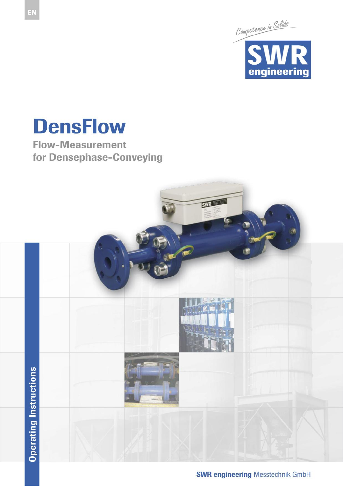
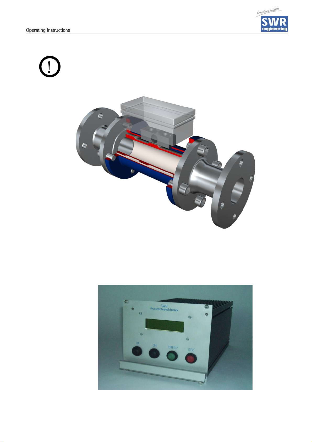
1 System Overview
Overview of the measuring system
Sensor (Measuring Pipe) Evaluation Unit
2 Function
• DensFlow is a measuri ng system especially developed for measuri ng the flow rate of
conveyed solids in densephase.
• DensFlow is working according to the latest micr oprocessor technology. By special
capacitive linking of an electromagnetic wave a homogeneous measuring field is
produced in the pipe.
• The electromagnetic wave brought into the pipe is reciprocall y acting with the solid
particles. These signals are evaluated in frequency and amplitude.
• The measurement of the solid speed is done by means of correlation. Two capacitive
sensors are used for the production of the correlation signals.
• A complete measuring unit consists of the sensor (measuring pipe) and the
evaluation unit.
Fig. 2: Coupling of the microwaves
3
Page 4

3 Safety
• The measuring system DensFlow was designed, built and tested to be safe and was
shipped in safe condition. Nevertheless persons or objects may be endangered by
components of the system if these are operated in an inexpert m anner. Therefore the
operational instruc tions must be read compl etely and the safety notes m ust be
followed.
In case of inexpert or irregular use, the manufacturer will refuse any liability or
guarantee.
3.1 Regular Use
• The measuri ng system must be instal led for measuring the flow rate onl y. Other usage and
modifications of the measuring system are not permitted.
• Only original spare part s and accessories of SWR engineering must be used.
• In order to prevent defects on the electronics, caused by e.g. electrostatic surge, the
flow velocity has to be below 50 m/s (e.g. free-blowing backwards).
3.2 Identification of Dangers
• Possible dangers when using the measuring system are marked by the foll owing
symbols i n the operating instructions:
Warning!
• This symbol in the operating instructions marks act ions, which may represent a
danger for life and limb of persons when carried out in an inexpert manner.
Attention!
• All actions which may endanger objects are marked with this sym bol in the operating
instructions.
3.3 Operational Safety
• The m easuring system must be install ed by trained and authori sed personnel only.
• Switch off the supply voltage for all maintenance, cleaning or inspection works on the
tubes or on components of the DensFlow. Follow the notes of the chapter
maintenance.
• The components and electrical connections m ust be checked for damages regularly.
If a damage is found, it is to be repaired before further operation of the instruments.
3.4 Technical Progress
• The m anufacturer reserves the right to adapt technical data to the technical progress
without parti cular advance notice. If you have any questions, SWR engineering will be
pleased to inform you on possible changes and extensions of the operating
instructions.
4
Page 5

4 Mounting and Installation
4.1 Delivery Range
• Measuring instrument in a 19"-rack system.
• Sensor for installation into the pipe.
• Seal-ring for adjustment to the pipe.
• Operating instructions.
4.2 Auxiliary
• Appropriate wrench or ring wrench for screwing.
• Tools for adjusting the wiring.
4.3 Mounting of the Measuring Pipe
• The sensor is to be mounted as follows:
• Determine the place of mounting on the pipe. On horizontal or incli ned pi pes the
sensor should be mounted from top.
• Follow the necessary distances of valves, bows, fans or cellular wheel sluices etc.
and also other measurement devices like temperature and pressure etc. to the sensor
(see fig. 3).
The mounting has to be in a vertical position.
Fig. 3: Minimal distances of the sensor to pipe bends and baffles.
5
Page 6
WARNING !
Before t he installat ion you hav e t o check, if there is a burr, a disalignm ent or a
seal in the i ntersection of the pipe and measuring sensor. If so, these
resistances in the pi pe must be removed.
Fig. 4: Installation of the sensor accommodation.
• The electronic equipment should be installed at a maxim um distance of 300 m from
the sensor. The housing is prepared for the 19"-rack system.
6
Page 7

4.4 Overview of the Connection of the Senor Pipe and Evaluation
Unit
Fig. 5: Wiring of the Sensor Pipe and Meas uring Instrument
A max imum length of 300 m of the sensor cabl e shoul d not be exceeded.
A 5-wired cable is needed between sensor and evaluati on unit.
7
Page 8

Electrical Connection
• Fig. 6: Electrical Connection
Evaluation Unit
Terminal No. Connection
Connection of the Supply Voltage
2a/c + 4a/c Input Supply Voltage +24 V DC
6a/c + 8a/c Input Supply Voltage GND
Connections
RS485
Throughput
Density
Velocity
Sensor
10a RS 485 Data A
12a RS 485 Data B
16c Output 4..20mA +
16a Output 4..20mA – (GND)
18c Output 4..20mA +
18a Output 4..20mA – (GND)
20c Output 4..20mA +
20a Output 4..20mA – (GND)
12c
22c Velocity A 0..20mA
24c Velocity B 0..20mA
28a/c Output Supply Volt age +24V +24V DC
32a/c Output Supply Volt age 0V GND
Density 0..20mA
8
Page 9

5 Commissioning
• For start-up the measurement system it is necessary to adj ust the sensor.
After swit ching on the power supply there is at least a warm-up time of 5
minut es required before any adjustment starts. Please check again :
• The correct cabl ing between sensor and the ev aluation unit.
• The correct adjustment of the sensor pipe.
Commissioning DensFlow
For start-up t he sensor has to be cal ibrated and param eterized to each
Basic Function At least a two-point-calibration (normally min and max)
product, which will be measured. It is necessary to assign
the mass flow to the display and i nitial value. The menu
functions are mostly sel f-explaining. Following a short
introduct ion to the overview:
By leaving the menu level and conf irmi ng the memory
function all values changed are transferred.
are suff icient for measuri ng the density f unction. Enter
the data in menu 3.5 and 3.6.
The v elocity measurement is firmly defined as an
absolute measurement by the distance of the sensor
plates and does not have to be cali brated.
Min-Poi nt Set point 1 to 0, when the mass flow is shut down and the
measuring pi pe is empty, calibrate this point now.
Max-Point Set point 2 to known maxi mum flow rate with normal
conveying and cali brate as well. Thi s value can be
adjusted later on when weighi ng by adjustment of
correcti on factor 2. 6.
Thus the basic f unction of t he measuring system is given
and it is now ready for operation
Adjustment See menu 2, point 1 to 6 f or the adjustment s to the
individual local condi tions regarding m aterial, measuring
units, etc.
Analog Output 1 is fi rmly configured for the m easuring of the throughput.
The measuring range is adjusted in menu point 2.2.
0 = 4 mA
Max =20 mA
Analog Output 2 is fi rmly configured for the m easuring of the vel ocity.
The measuring range is adjusted in menu point 2.1.
0 = 4mA
Max = 20mA
Analog Output 3 is fi rmly configured for the m easuring of the vel ocity.
The measuring range is fix adjusted to
0 m/s = 4 mA
10m/s = 20 mA
9
Page 10

Average The measuring range filter is used for the adjustment to
slower working devices or for a continuous output of the
analog output.
Menu point 2.3 for velocity and
Menu point 2.4 for density.
Storage Adjusted values are conf irmed by pressing t he ENTER-
button. Leaving the menu level by pressing the ES Cbutton. All changes are autom aticall y stored and the new
values are set as standard.
Suggestion for the Calibration Procedure:
Step 1 Input of the requested throughput value of the final value of the measuring range
in menu point 2.2
e.g.: 20mA = 20000 Kg/h
Step 2 Input of the requested density value of the fi nal value of the measuring range in
menu point 2.1
e.g.: 20mA = 800 Kg/m³
Step 3 Alignment of the mini mum densit y val ue with empty pipe.
min = 0 kg/m³ i n menu point 3. 5
Step 4 Alignment of the maximum densi ty value by complete fi lled pipe (e.g. 800 kg/m ³)
in menu point 3.6
Step 5 Input the di ameter of the pipe in menu point 2.5
Step 6 Conveying of the product on maximum throughput rate over a constant time
interval (e. g. 10 min. ). During this time period the throughput must not change.
Step 7 Measurement of the throughput quantity by weighi ng.
Step 8 Calculat ion of the correction factor by diff erentiati on
Value measured
Correction factor = -------------------------
Value weighted
Step 9 Correction of the m easured value by entering the correction f actor in m enu
point 2.6
10
Page 11

6 Menu Structure of DensFlow
1.1 Display
Density
1.2 Display
Throughput
1.3 Display
Velocity
2. Options
1.4 Display
Totalisator
2.1 – Density measuring range
2.2 – Throughput measuring
range
2.3 – Average velocity
2.4 – Average density
2.5 – Pipe diameter
2.6 – Correction factor
2.7 - Send parameters
2.8 - Language
11
3. Service menu
3.1 - ADC-1 (Density)
3.2 - ADC-2 (Velocity)
3.3 - DAC-Simulation
3.3.1 - DAC1 (preset 4,8,12,16,20mA)
3.3.2 - DAC2 (preset 4,8,12,16,20mA)
3.4 - Density min-value
3.5 - Density max-value
3.6 - Velocity Range
3.7 - DAC-Calibration
3.7.1 - Ofs DAC1
3.7.2 - Ofs DAC2
3.7.3 - v DAC1
3.7.4 - v DAC2
3.8 - Slave Adress
Page 12

7 Menu Parameters of the System in Detail
1. Display of the Measured
Values
1.1 - Density 2.1 - Density measuring range
1.2 - Throughput 2.2 - Throughput measuring range
1.3 - Velocity 2.3 - Average v elocity 3.3 - Current output
1.4 - Totalisator 2.4 - Average density 3.4 - Density min value
2. Options 3. Diagnosis
3.1 - A/D-1 (Density)
[kg/m³]
3.2 - A/D-2 (Velocity)
[kg/h]
(mA – preset)
2.5 - Pipe diameter [mm] 3.5 - Density max
value
2.6 - Correction fact or 3.6 - V elocity measur ing range [m/s]
2.7 - Send param eters 3.7 - DAC-Calibration
2.8 - Language 3.8 - Slave Adress
Use of the Evaluation Unit by:
ENTER-button à Selection and Confirming
UP- / DN-button à Changing
ESC-button à Backwards
1.0 Display:
1.1 Displ ay of t he measured density i n kg/m ³
1.2 Display of t he cal cul ated throughput from
density and velocity [kg/h]
1.3 Displ ay of t he measured veloci ty i n m/ s
DENSITY
0.0 Kg/m3
THROUGHPUT
0.0 Kg/h
VELOCITY
0.00 m/s
12
1.4 Displ ay of t he tot al flowrate since last reset
TOTALISATOR
0.00 Kg
Page 13

2. Options:
Press ENTER Button
OPTIONS
2.1 Entry of the density measuring range in
50 kg/m³ - steps.
2.2 Ent ry of the throughput range in 100 kg/m³ - steps.
Final value of measuri ng range [kg/h] = 20mA
2.3 Entry of the average time for the
velocity (0..120s)
à Damping of the signal
2.4 Entry of the average time for the
density (0.. .120s)
à Damping of the signal
2.5 Entry of the pipe diameter in mm.
Necessary for the cor rect calculation
of the quant ity.
2.6 Entry of the correction factor for the
throughput (0.1...10)
Here the value received can be corr ected
lateron by changing the preset value to 1.
Density Range
= 800 [Kg/m³]
Throughput Range
= 20000 Kg/h
Average V
= 10s [ 25 ]
Average D
= 10s [ 25 ]
Pipe Diameter
= 32.0 mm
Correction Factor
= 1.0
2.7 Send parameter
By pressing YES the parameters factor correction,
throughput range, densi ty measuring range will be
send via RS485 interface to all connected instrum ents
2.8 Select Language
between German and English
Parameter send
= No / Yes
Language
English
13
Page 14

3. Service menu:
To get int o the diagnostic mode press
ESC and ENTER button at the same time
Service menu
3.1 Display current val ue A/D-c onverter 1 (Density)
3.2 Display Vol t age level A/D-c onverter 2 (Veloci t y)
3.3 Select i on Current value f or test purposes.
Here a constant current ( 4, 8, 12, 20m A)
can be presetted on output 1 for testing purposes.
Here a constant current ( 4, 8, 12, 20m A)
can be presetted on output 2 for testing purposes.
ADC 1 (Density)
I=0.0mA [ 0h]
ADC 2 (Velocity)
I=0.0mA [ 0h]
DAC Simulation
DAC 1 [ENTER]
I = 04mA
DAC 2 [ENTER]
I = 04mA
3.4 Entry of the mi ni m um value f or the densit y range.
usually 0-value (Measuring pipe empt y).
The dim ensi onless value must be changed
so far, until 0% are indicated.
3.5 Entry of the max i mum v al ue for the density range.
Here you can enter the value, which can
maximally be expected or a second measuring
point. T he dimensionless value must be changed
so far, until the requested percentage is indicated.
3.6 I nput of the v eloci t y
Standard = 10m/s ex works presetted.
3.7 DAC- Cal ibrat ion f or current outputs
press ENTER to select subm enu
Offset Calibration
for 4 mA output 1 (throughput)
Density Min
= 0072 [ 0.0%]
Density Max
= 2568 [ 100%]
Velocity range
= 10.0 m/s
DAC-Calibration
DAC-Calibration
Of's DAC1 +0
14
Page 15

Offset Calibration
for 4 mA output 2 (densit y)
DAC-Calibration
Of's DAC2 +0
Span Calibration
for 20 mA output 1 (throughput)
Span Calibration
for 20 mA output 2 (densit y)
3.8 Slav e Adress
select slave adress for ModBus - comunication
Totalisator
with the totalisator function it is possible to m onitor
entire flow rate since the last reset of the Totalisator
A RESET of the counts can be accomplished over
pressing the ENTER and selection of YES or NO
with UP / DOWN button.
DAC-Calibration
V DAC1 +1
DAC-Calibration
V DAC2 +1
Slave Adress
001
TOTALISATOR
1,0 Kg
TOTALISATOR
Reset: 'NO'
Stop Totalisator
press ESC
TOTALISATOR
H: 1,0 Kg
15
Page 16

8 Maintenance
• Warning!
Danger of shock with opened housing!
• Switch off the suppl y voltage for all maintenance or repair works on the measuring
system. The pipe must not be in operati on during a sensor exchange.
• Repair and mai ntenance work must be carri ed out by trained or expert personnel only.
9 Warranty
Warr anty is granted for two years starting from deli very date under the conditi on t hat
the operational instructions have been followed, no interventions on the appliances
have been m ade and the components of the system show no mechanical damage or
wear resist ance.
In case of a defect during the warranty period, defective components are repaired or
are replaced free of charge. Replaced parts turn into the property of SWR. If desired
by the customer that the part s should be repaired or replaced in its factory, then the
customer has to take over the costs for the SWR-service staff.
SWR is not responsible for damage, which did not develop at the delivery arti cle;
especially SWR is not responsible for escaped profit or other financial dam ages of
the customer.
10 Trouble shooting
• Warni ng!
The electrical installation must only be checked by expert personnel.
Problem Cause Measure
Measuring system
does not work.
Measuring system
outputs wrong values
Relay flickering Hysteresis too small.
Power supply interrupted.
Break of a cable.
Fus e defective.
Device defect ive.
Calibration not correct.
Calibration shifted by
abrasion on front end of
sensor.
Check the power supply.
Check the connecting cables for a possible
break of a cable.
Exchange the fuse in the field housing .
Delete input signal correction, new calibration
according to section 6.
Delete input signal correction, new calibration
according to section 6.
Increase hysteresis, check effects caused by
exter nal devi ces.
Do not open, as otherwise the warranty claim expires!
16
Page 17
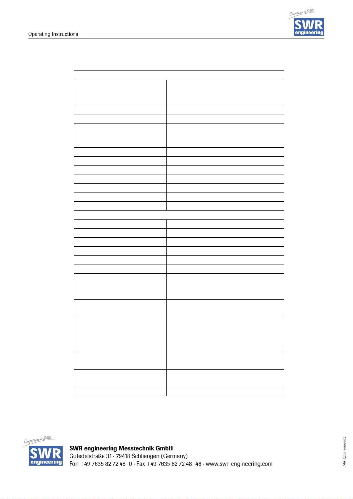
11 Techni cal Data
Sensor Pipe
Housing: Steel St52, powder-coated
(stainless steel 1.4541) option
NW 10.. ..250, Flange DIN 2576
Inner pipe: Ceramics, POM, PTFE
Protection category: IP65
Operating temperature: Sensor pipe: -20....+ 120 °C
Option: -20....+ 220 °C
Sensor electronic: 0....+ 60 °C
Max. working pressure: 10 bar, option20 bar
Max. accept. flow velocity 50 m/s
Working frequency: 100kHz
Transmitting power: max. 2 mW
Weight: Depending on nominal size
Dimension: Ø NW + 90mm , L 500mm
Accuracy: +/- 2...5% i n calibrated range
Evaluation Unit
Supply voltage: 24V DC
Power consumption: 12 W
Operating temperature: –10...+45 °C
Dimension: 19"-rack system, 3HE, 28TE, L=227mm
Weight: approx. 0.7 kg
Additional Data:
Input: 2 x Velocity 0..20mA or 0..10V
1 x Density 0..20mA
1 x PFM-Input 14V, Imax 35mA, 30..3kHz
Connections: Connector (DIN 41612)
Type B, 32-pol., connector
Current output: Throughput: : 4...20mA
Density : 4...20mA
Velocity : 4...20mA
Load < 500 Ω
Serial output: RS232 / 485, MOD-Bus-Prot ocol
Sub-D 9-pol., connector
Control unit: LCD-Display, li ghted, 16 x 2 digi ts
4 x push buttons
Data storage: EEPROM
17
EN 070507
 Loading...