

S WR
BASS 350
USER GUIDE
SWR
8860 E. Chaparral Rd. Suite 100
Scottsdale, AZ 85250-2618 USA
PHONE: (480) 596-9690
FAX: (480) 367-5262
EMAIL: custserve@fenderusa.com
WEB: swrsound.com
© 2001 SWR

IMPORTANT SAFETY INSTRUCTIONS
CAUTION: TO REDUCE RISK OF ELECTRIC SHOCK, DO NOT REMOVE THE COVER OR BACK.
NO USER-SERVICEABLE PARTS INSIDE. PLEASE REFER TO A QUALIFIED SERVICE TECHNICIAN.
A. Read Instructions: All safety and operation instructions should be read before the product is operated.
B. Retain Instructions: The safety and operating instructions should be retained for future reference.
C. Heed Warnings: All of the warnings on this product and in the operating instr uctions should be adhered to.
D. Follow Instructions: All operating and use instr uctions should be followed.
E. Cleaning: Unplug this product from the wall outlet before cleaning. Do not use liquid cleaners or aer osol cleaners. Use a
slightly damp cloth for cleaning.
F. Water and Moisture: Do not use this product near water; for example, near a swimming pool, wet basement, and the like.
G. Accessories: Do not place this product on an unstable cart, stand, tripod, bracket or table. The product may fall, causing
serious injur y to a child or adult, and serious damage to the pr oduct.
H. Ventilation: Slots and openings in the unit are provided for ventilation and to ensure reliable operation of the product, to pro-
tect it from overheating, thus these openings must not be blocked or covered. This product should not be placed in a built-in
installation such as a bookcase or rack unless proper ventilation is provided or the manufacturer's instr uctions have been
adhered to.
I. Grounding: This product is equipped with a three-wir e grounding-type plug, a plug having a thir d (gr ounding) pin. This plug will
only fit into a grounding-type power outlet. This is a safety feature. If you are unable to insert the plug into the outlet, contact
your electrician to replace your obsolete outlet. Do not defeat the safety purpose of the grounding-type plug.
J. Power Cord Protection: Power supply cor ds should be routed so that they ar e not likely to be walked on or pinched by items
placed upon them, paying par ticular attention to cor ds at plugs and the point where they exit the pr oduct.
K. Lightning: For added protection of this product during a lightning stor m or when it is left unattended and unused for long
periods of time, unplug it from the wall outlet. This will prevent damage to the product due to lightning and power-line sur ges.
L. Overloading: Do not overload wall outlets or extension cords as this can result in a risk of fir e or electric shock.
M. Object and Liquid Entry: Never push objects of any kind into this product through the openings as they may touch dangerous
voltage points or shor t out parts that could r esult in a fire or electric shock. Never spill liquid of any kind on the pr oduct.
N. Servicing: Do not attempt to service this pr oduct yourself as opening or removing covers may expose you to danger ous
voltage or other hazards. Refer all servicing to qualified service personnel.
O. Damage Requiring Service: Unplug this product from the wall outlet and r efer servicing to qualified service personnel under
the following conditions:
1) When the power supply cord has been damaged
2) If liquid has been spilled or objects have fallen into the product
3) If the product has been exposed to rain, water, or other conductive liquids
4) If the product does not operate normally by following the operating instr uctions
5) If the product has been dropped or damaged in any way
6) When the product exhibits a distinct change in performance.
P. Replacement Parts: When replacement parts are r equired, be sur e the service technician has used r eplacement parts specified by the manufacturer or have the same characteristics as the original par t. Unauthorized substitutions may r esult in fire,
electric shock, or other hazards.
Q. Safety Check: Upon completion of any ser vice or r epairs to this product, ask the service technician to perform safety checks
to determine that the product is in proper operating condition.
R. Heat: The product should be situated away from heat sour ces such as radiators, heat registers, stoves or other pr oducts that
product heat.
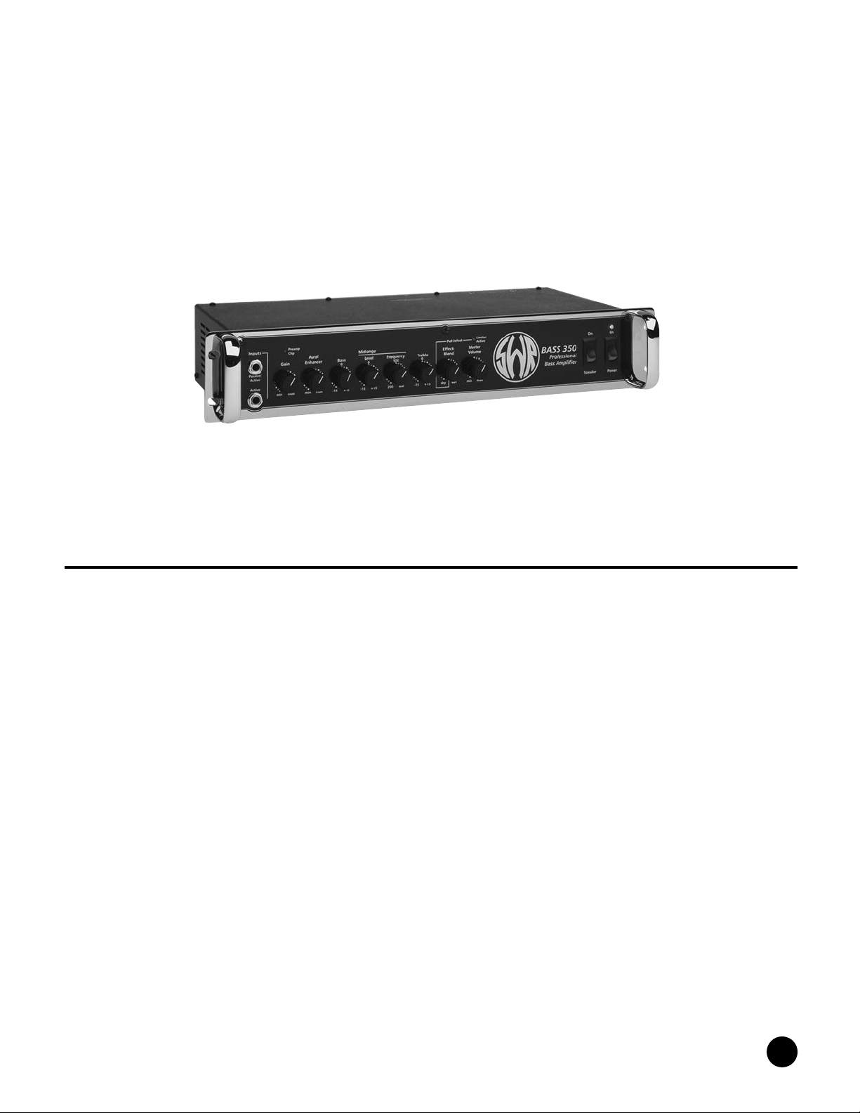
SWR BASS 350 USER GUIDE
INTRODUCTION
The SWR Bass 350 Bass Amplifier was designed for the player who
prefers a simple and straightforwar d preamp combined with a power
amp capable of delivering enough power and headroom for most live
applications. The Bass 350 maintains the same quality components
and materials found in all SWR products and is assembled by hand at
our factory in California.
The two preamp gain stages utilize a specially-selected Groove Tubes
12AX7A. The tone controls incorporate ICs and the power amp is
designed with very high quality bi-polar devices. Each type of device
was chosen for its perfor mance and reliability in the application used.
The front panel of the Bass 350 is chromed steel, while aluminum is
used for the main chassis because of its superior electrical and thermal characteristics and light weight. All primary electrical components
are U.L. approved and SWR uses Belden Cable for all shielded wire.
Everyone at SWR sincerely hopes that the pur chase of our product
adds to the enjoyment of your playing and that it lives up to all your
expectations and more!
Sincerely,
SWR
1
BASS 350 USER GUIDE

SWR BASS 350 — SPECIFICATIONS
Note: All measurements wer e taken with a line voltage of 120VAC. All noise specifications are
“unweighted.” All voltages and watts are “RMS.” All measurements were taken with tone contr ols
set flat, Aural Enhancer at minimum.
POWER (minimum)
450 Watts @ 2 ohms
350 Watts @ 4 ohms
240 Watts @ 8 ohms
FREQUENCY RESPONSE (Power Amplifier)
–3dB @ 20 Hz and 40 kHz
SENSITIVITY (full output under clipping, 8 ohms load, 100 Hz)
Passive Input Jack: 38 millivolts
Active Input Jack: 60 millivolts
Power Amplifier (Ef fects Retur n Jack “in”): 5 volts
INPUT IMPEDANCE
Passive/Active Input: 800k Ohms
Active Input: 60k Ohms
Ef fects Retur n: 27k Ohms
OUTPUT IMPEDANCE
Ef fects Send: 100 Ohms
Tuner Send: 100 Ohms
Crossover Low and High Outs: 100 Ohms XLR
Balanced Out: .750 Ohms
SIGNAL TO NOISE RATIO: –72 dB (<10 millivolts typical)
EQUIVALENT INPUT NOISE: 9 microvolts
DIMENSIONS: 19" W x 3.5" H x 10.125" D
WEIGHT: 21 lbs.
BASS 350 — FRONT PANEL FEATURES
PASSIVE/ACTIVE INPUT JACK
This input jack is designed to accommodate both “passive” instruments, and most “active”
instruments. A passive instr ument has no built-in pr eamp and does not use a battery, while an
“active” bass utilizes a battery operated preamp for gain, tone contr ols, or both. The Passive/
Active Input will work with all instruments having a maximum output of less than 1 volt RMS.
Some active pickups, such as EMG, Bartolini, etc., use batteries for operation and will work perfectly using this input. Additionally, instruments made by Pedulla, Tobias, Sadowsky, Modulus
Graphite, etc., have active electronics that are suited for use in the Passive/Active input.
Generally speaking, try this input first. If you hear a small amount of distortion and the preamp
clip LED is not activated, try using the Active input jack. If using the Active input does not cor rect
any audible distortion, check the battery in your bass.
2
BASS 350 USER GUIDE

Note: If you want to overdrive the first TUBE stage, use an exter nal preamp between your
instrument and the Passive input. To obtain optimum sound when trying this, make sur e the
preamp clip LED is not activated. If this occurs, turn down your Gain control until the LED
does not light. The first preamp tube stage is NOT monitored by the preamp clip cir cuit for
this reason.
ACTIVE INPUT
The Active input jack should be used with instruments having a built-in (on board) pr eamp or other
sound sources that will produce output levels greater than 1 volt RMS. Some of these basses
are the Kubicki X-Factor and some older Ovation electrics. Some really “hot” pickups installed in
your instrument may sound better through the Active input. The best judge is your own ears.
If you’re using a keyboard or bass pedal with the Bass 350, we have found the best choice to be
the Active input.
Note: Using the Active input with passive basses (active instr uments will always employ a
battery) may result in a loss of high end transients. Players who r oll off their high end starting at about 2kHz, or prefer a “darker” sound, may find this input more to their liking.
If you hear some distortion with your active bass and are using the Active Input, make sur e the
preamp clip LED indicator is not lighting. If the preamp stage is not being driven into clipping,
replace the battery in your instr ument.
GAIN CONTROL
The Gain control adjusts the volume of the preamp section. Since the Gain control is similar to a
“pad,” a small amount of signal will be heard even with the Gain control rotated fully counterclockwise (with the Master Volume up).
After all EQ settings and the Aural Enhancer are set, the Gain control should be raised until the
preamp clip LED barely flashes when your loudest note is str uck. This will insure maximum signal
to noise ratio and prevent unwanted clipping of the preamp section.
Note: The Gain can serve as an EFFECTS SEND LEVEL ADJUSTMENT. If your ef fect is being
overdriven, turn down the Gain control and r e-adjust your Master volume for overall loudness.
PREAMP CLIP LED
The preamp clip LED will light whenever the preamp, tone section or output buffer reach clipping
(run out of headroom). This function does NOT monitor the first tube stage of the Passive input.
See that section for more info.
In the event the clip indicator lights, turn down the Gain control. Since this cir cuit monitors the
tone controls, boosting any one of them can cause the clip LED to activate. Once again, you may
leave the tone control at its desired level, but turn the Gain contr ol down further.
AURAL ENHANCER
The Aural Enhancer was developed to bring out the fundamental low notes of the bass guitar, reduce
certain frequencies that help “mask” the fundamentals, and enhance high end transients. This effect
becomes more pronounced as the control is tur ned to maximum. The r esult is a mor e transpar ent
sound and is especially noticeable with a slap style of playing. A particularly favorite setting for live
gigs is at about 2 o’clock. This position of the Enhancer brings out both the low end fundamentals
and crisp highs and, at the same time, adds a little lower midrange to help cut through the band.
3
BASS 350 USER GUIDE

ACTIVE TONE CONTROL SECTION
BASS CONTROL
The Bass Control employs a shelving type circuit and boosts or cuts the bass response +/–15dB,
from about 30 Hz to 100 Hz. Starting at mid-center click-position, tur ning the control counter
clockwise cuts the bass response and turning the control clockwise boosts the bass r esponse.
MID RANGE SECTION
LEVEL CONTROL
The Level control cuts or boosts the frequency set by the Frequency contr ol. Starting at mid-position, turning the Level control counter clockwise cuts the desired tone. Turning the Level control
clockwise boosts the desired tone (set by the Frequency control). When the level contr ol is set at
mid (center click) position, turning the frequency control will have no effect on the sound.
To find the midrange area you are looking for:
1. Adjust the LEVEL control to the full boost or cut position.
2. Rotate the Frequency control until the desired ar ea you wish to cut or boost is found.
3. Adjust the Level control to the desired amount of cut or boost
FREQUENCY CONTROL
The Frequency control sets the area that is to be cut or boosted by the Level function. If the Level
control is set at mid-position, turning the Frequency knob will have NO effect.
Some hints: If you need to “cut through” the band a little more, try boosting 200 to 400 Hz. If
you like a more transparent sound, try cutting at 800 Hz. The midrange area is especially useful
in controlling fretless basses and their inherent qualities.
TREBLE CONTROL
The Treble Control employs a shelving type circuit and boosts or cuts the high frequencies and
their octaves +/–15dB from about 2kHz to 14kHz. Starting at mid-center click-position, tur ning the
control counter clockwise cuts the treble response, while tur ning the control clockwise boosts the
treble response.
EFFECTS BLEND
The Ef fects Blend Contr ol “blends” the signal sent from your instr ument with the signal coming
from your effects unit. With the Effects Blend full counter clockwise (“dry”), no signal from your
ef fects will be hear d. As you turn this contr ol clockwise, more of the effect can be heard in the
overall sound. When the Blend knob is fully clockwise (“wet”), no true or unaffected signal is
heard other than what your effects unit provides. If your effects unit has a similar control, adjust
it to the full (wet) position. This will avoid any possible phasing problems.
The Blend circuit is similar to that used on recording consoles with the effects loop on a “side
chain” to the normal circuit. Unless the contr ol is set to the full wet position, you will always get
the full sound of your instrument AND get the diversity an effects unit offers. This circuit is also
ef fective in r educing noise generated by effects units because it is located after the gain stages
in the preamp.
4
BASS 350 USER GUIDE

The Ef fects Blend functions only when the Effects Loop is being used. It is activated when a 1/4"
phone plug is inserted into the Effects Receive jack (see the “Effects Loop” section for mor e
information).
Note: Pulling the Effects Blend contr ol knob outward defeats the inter nal limiter cir cuit. To
activate the limiter, push the control in.
MASTER VOLUME
The Master Volume adjusts the level being sent to the power amplifier in your Bass 350—it controls the overall volume of the unit. It does not affect the level of the recor d XLR output in the
“line” position.
Losses in level caused by ef fects units can be r ecovered by incr easing the Master Volume.
FAN & FAN DEFEAT SWITCH
The power amp is cooled by an extruded aluminum heatsink and a ther mostatically contr olled fan.
This fan turns on when the heatsink reaches 50 degrees centigrade and tur ns itself off when the
heatsink reaches 40-45 degrees centigrade. This allows for “silent r unning” when used at low volumes. Be sure to leave at least a 1/2" clearance between the vent on the left side of the Bass
350 and the side of any rack case or enclosure you should happen to install your amp in. This will
allow for the heat generated by internal components to escape.
Setting the Fan Defeat Switch to the “Fan” position activates the internal cooling fan’s normal
operating mode. Setting the Fan Defeat Switch to the “Defeat” position deactivates the cooling
fan regardless of the internal temperatur e of the unit. For this reason, it is r ecommended that the
Fan Defeat Switch be set to the “Fan” position for the majority of the time that the amplifier is in
operation. Please note that it is normal for the cooling fan to be audible at low levels. We recommend deactivating the fan only in situations where the noise floor is so low that normal fan noise
might be noticeable or distracting, such as recording situations where a micr ophone is used in
close proximity to the unit.
POWER ON/OFF SWITCH
Setting the Power On/Of f switch to the “On” position switches on the Bass 350. The power LED
will light up. Setting the Power On/Of f switch to the “Off” position switches of f the unit.
LIMITER/COMPRESSOR CIRCUIT
The Limiter found in the Bass 350 is a soft knee type limiter. The Limiter circuit is located after
(post) the Master Volume and before (pre) the power amplifier. Therefore, the limiter is driven by
the Master Volume. Its threshold (starting point) is preset by the factory so that the user can get
maximum overall apparent volume without unduly overdriving the power amplifier or internal speakers. This can be helpful in preventing speaker damage when running your system at high volume.
You may either activate or defeat the limiter via the Effects Blend Contr ol. The “In” position activates the Limiter Circuit. The “Out” position defeats this feature.
LIMITER ACTIVE LED
When the threshold (starting point) of the Limiter Cir cuit is reached, the Limiter Active LED will
light, indicating that the Limiter Circuit is active. The Limiter LED will be inactive when the Limiter
is defeated or when playing at lower levels.
5
BASS 350 USER GUIDE

REAR PANEL FEATURES
BALANCED XLR OUT
The Balanced XLR out is a true electronically balanced r ecord out. The signal appearing at the
XLR out is governed by the position of the Line/Direct switch. In the LINE position, all front panel
controls are functional except the Master Volume, and the signal is essentially the same as that
heard through your speaker system. The output level in the Line position is adjusted by the GAIN
control on the front panel. If you are using an effect, this will also appear mixed in the signal
when you are in the line mode.
In the DIRECT position, the Balanced XLR out becomes an active TUBE direct box. No front panel
controls are functional and the level is only adjustable via your instr ument.
Wiring for the XLR connector is as follows:
Pin 1 = ground, Pin 2 = +, Pin 3 = – (minus) (American Standard)
LINE/DIRECT SWITCH
The Line/Direct switch gives the user the option of either a line signal (preamp out) or direct signal from the instrument. The signal appearing at the XLR out is slightly “hotter” than normal DIs.
You may want to inform the live soundperson or recording engineer of this.
To use the Line/Direct function, position the knob in the desired location. Make sure the switch
is all the way to the left or right to avoid an intermittent condition.
Note: Turn of f transients appear at the recor d outs when the amplifier is shut down. It is
recommended that equipment being used in conjunction with the record out be tur ned down,
of f, or disconnected BEFORE the Bass 350 is tur ned off.
TO TUNER INPUT
The To Tuner input allows the user to plug an instrument tuner into this jack and tune up without
having to unplug and go back and forth from amp to tuner. This feature is totally isolated from the
rest of the preamp and will function regardless of the settings on the fr ont panel. Being isolated on
a side chain avoids loading down of the instrument, which can cause a loss in dynamic range.
To use this feature, connect a shielded patch cord from the To Tuner input to the input jack on
your tuner. Turn the amplifier on and you're ready to go. If you do not wish to monitor your sound
during the tuning process, you may turn down the Master Volume.
EFFECTS LOOP
The Ef fects Loop is used in conjunction with the Effects Blend control on the front panel. When
the Ef fects Blend Contr ol is in the full counter-clockwise (dry) position, no ef fects will be heard.
The Ef fects Loop is compatible with most individual or multi-effect ef fect units. It is designed as
a “side chain” function and works exactly like those found on studio consoles. Many ef fects on
the market have input level adjustments. For instance, some units have a switch that you can set
for either –10 dB or +4 dB. In all cases, these should be set for 0 dB (if available) or +4 dB. The
level going to your ef fect is contr olled by the Gain control on the Bass 350’s fr ont panel.
Use of the ef fects loop should gr eatly reduce the noise generated by effects units (as compar ed
to using the ef fect between your instr ument and the input jack). This is because the loop is after
the preamp gain stages.
6
BASS 350 USER GUIDE

SEND
Run a shielded patch cord from the SEND jack to the INPUT of your effects unit. The output
impedance of the Ef fects Send Jack is 100 ohms. This jack can be used as a line level output for
use in conjunction with a slave power amp such as SWR’s Power 750. It may also be used as an
unbalanced record out.
RECEIVE
Run a shielded patch cord from the Bass 350 RECEIVE jack to the OUTPUT jack of your effects unit.
All patch cords used with effects should be as short as possible and should be routed as direct
as possible. Running patch cables over the top of the Bass 350 (as with any amplifier) can
induce hum in the cables and is not recommended.
A unique feature of the Receive jack is the ability to practice a part along with pr e-recor ded music.
To accomplish this, insert a tape recorder or other sound sour ce into the Receive jack (make sur e
it is a MONO source). Using the Blend control, adjust the level of recor ded music fr om the Receive
to the “live” sound of your instrument. The mixed sound will be heard thr ough your speakers. This
is also an excellent way to practice along with a drum machine.
Input impedance of the Receive jack is 27k ohms minimum.
Note: Inserting a plug into the Receive jack activates the Ef fects Blend control. The contr ol
receives this command through the ground cr eated by the phone plug making contact with
the jack. The plug must be a mono plug (tip and ground). If you have a stereo plug only, it
will be necessary to tie the ring and the ground together.
SPEAKER JACKS
Two 1/4" phone jacks and two Speakon®Jacks (wired in parallel) are provided for connection of
the Bass 350 to your speaker system. The minimum load (or impedance) that can be used with
the Bass 350 is 2 ohms total. In other words, you can connect two 4 ohm, four 8 ohm or eight
16 ohm enclosures to the Bass 350. That said, we recommend a total load of 4 ohms for best
performance.
Whenever possible, use the Speakon jacks. Speakon jacks and connectors of fer the best possible connection and are far superior to banana or 1/4" phone jacks in that they not only lock in
place (preventing accidental disconnection), but also offer a greater and more stable connection
surface. This solid connection provides a mor e effective transfer of power to your speakers.
Only SPEAKER CABLE of 18 gauge or heavier (the heavier the cable, the lower the gauge) should
be used to connect your Bass 350 to your speaker system. Do not use shielded instrument cable
to connect your amplifier to your speaker enclosure, as this can result in inter mittent power loss,
cause your amp to oscillate and damage itself and/or your speakers, and render the cable useless for any purpose.
Note: Unlike most amplifiers on the market, the Bass 350 can be used for recor ding purposes without speakers attached to the speaker jacks (using only the XLR Output).
Recommended single SWR Speaker enclosures for use with the Bass 350 include:
• Big Bertha
• Henry the 8x8
• Triad
• Goliath III
• Goliath Junior III
7
BASS 350 USER GUIDE

Recommended SWR Speaker combinations for use with the Bass 350 include:
• (2) Goliath IIIs
• (2) Goliath Junior IIIs (8 ohm version)
• (2) Son Of Berthas
• (1) Goliath Junior III & (1) Son Of Bertha
• (1) Goliath Junior III & (1) Big Ben
• (1) Goliath III & (1) Goliath Junior III
SPEAKER FUSE
The speaker fuse is provided to protect your speakers in the unlikely event of a power amp failure
or to protect your power amplifier from incor rect speaker impedances or hookups. Size and rating
of the fuse is 3AG, 10 amp, fast blow. Do not defeat the purpose of this feature by using a higher
rated fuse as it can damage your amplifier and void your warranty.
The fuse can open as a result of a fault in the speaker cable, the speakers themselves, or the power
amp being sent well into clipping. With this in mind, it is wise to carry extra fuses at all times.
A/C OR MAINS FUSE
This fuse is provided to protect the internal electr onics against power sur ges, etc. It also pr otects
the unit against itself should one of the internal components fail. If this fuse should open,
replace it with the same type of fuse and rating. Do not defeat the purpose of this feature by
using a higher rated fuse as it can void your warranty.
Proper size of the AC fuse for all countries is 3AG. Proper rating of the fuse is as follows:
Japan: 8 amp slo-blo
United States: 7 amp slo-blo
Europe (240V): 4 amp slo-blo
A/C CORD RECEPTACLE
Accepts a standard A/C power cable (supplied with the Bass 350 in the United States) used with
almost all current musical, pr ofessional and household electronic devices. We recommend great
care when packing up. If your unit is not in a rack case, put the cable in your instrument or accessory case or leave it attached and looped around one of the rack handles. If it does become misplaced, a replacement cable can be purchased at almost any music or computer store.
Note: The rating for this cable is 3 conductor, 10 amperes minimum. Look for this rating on
the cable. Make sure the cable is plugged in all the way in both the amp and the wall socket.
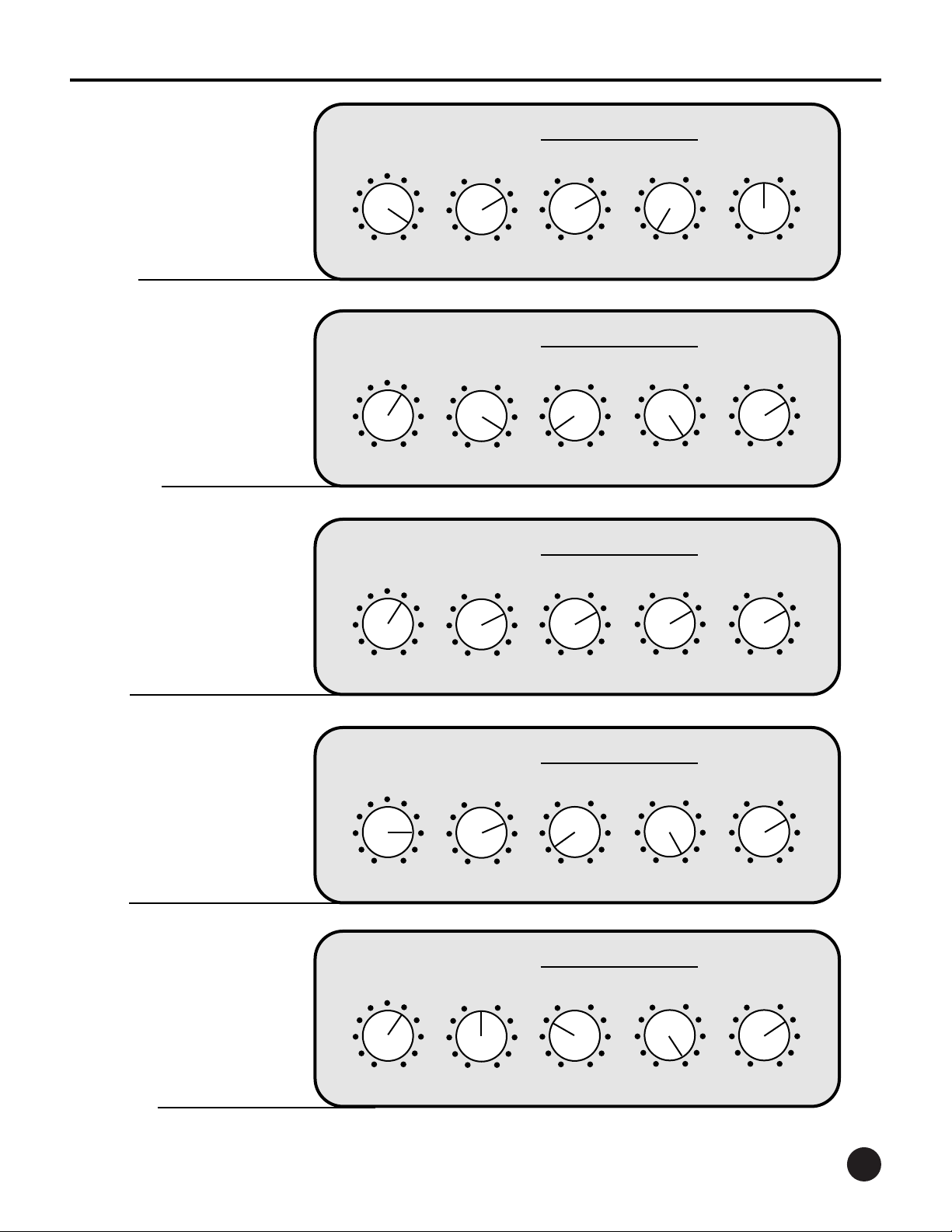
SUGGESTED SETTINGS
The following page includes examples of tone control options for various styles of music. These
settings are intended for use as a starting point for dialing in your own individual sound, so feel
free to make adjustments based on your own playing style, instrument, and speaker
8
BASS 350 USER GUIDE
9
Aural
Enhancer
Bass FrequencyLevel Treble
Midrange
0
0
0
500
+15
-15 200
800
min
max
+15
-15
+15
-15
Aural
Enhancer
Bass FrequencyLevel Treble
Midrange
0
0
0
500
+15
-15 200
800
min
max
+15
-15
+15
-15
Aural
Enhancer
Bass FrequencyLevel Treble
Midrange
0
0
0
500
+15
-15 200
800
min
max
+15
-15
+15
-15
Aural
Enhancer
Bass FrequencyLevel Treble
Midrange
0
0
0
500
+15
-15 200
800
min
max
+15
-15
+15
-15
Aural
Enhancer
Bass FrequencyLevel Treble
Midrange
0
0
0
500
+15
-15 200
800
min
max
+15
-15
+15
-15
SWR BASS 350 — SUGGESTED SETTINGS
ROCK
REGGAE
JAZZ
SLAP
STUDIO
BASS 350 USER GUIDE

BASS 350 LIMITED WARRANTY
The BASS 350 from FMIC is warranted to the original consumer purchaser for TWO YEARS from the
date of purchase, against defects in materials and workmanship and provided that it is purchased from
an Authorized SWR Dealer. This warranty applies only to products purchased in the USA or Canada.
This warranty is VOID if the unit has been damaged due to accident, improper handling, installation or
operation, shipping damage, abuse or misuse, unauthorized repair or attempted repair, or if the serial
number has been defaced or removed. FMIC reserves the right to make such determination on the
basis of inspection by an Authorized FMIC Service Center.
All liability for any incidental or consequential damages for breach of any expressed or implied
warranties is disclaimed and excluded herefr om.
Some states do not allow limitations on how long an implied warranty lasts, or the exclusion or
limitation of incidental or consequential damages, so that the above exclusion may not apply to
you. This warranty gives you specific legal rights and you may also have other rights which vary
from state to state.
SHOULD YOUR SWR AMPLIFIER REQUIRE SERVICE OR REPAIR,
PLEASE USE THE FOLLOWING PROCEDURE:
Locate your original receipt showing details of purchase including date of purchase, model, and serial number.
Locate your nearest Authorized FMIC Service Center by calling FMIC Consumer Relations at: (480) 596-7195, or
on the web, at: http://www.mrgearhead.com/faq/allservice.html
To receive warranty service, return the complete product to an Authorized FMIC Electronics Service Center, with proof
of purchase, during the applicable warranty period. Transportation costs are not included in this Limited Warranty.
Defective products that qualify for coverage under this warranty will be repaired or replaced, at FMIC's discretion,
with a like or comparable product, without charge.
➊
➋
➌
➍
For a complete list of Authorized FMIC
Service Centers, and the latest SWR
news, interviews,and more,
check out our website:
PHONE: (480) 596- 9690
FAX: (480) 367-5262
EMAIL: custserve@fenderusa.com
WEB: swrsound.com
swrsound.com
SWR
8860 E. Chaparral Rd. Suite 100
Scottsdale, AZ 85250-2618 USA
 Loading...