

Page 1

RS
SM
RS 125 R 2016
SM 125 R 2016
Manuale rapido
Quick Reference Manual
Guide rapide
Kurzanleitung
Guía rápida
Cope_retro QUICK RS-SM_125_MY16_ed00_11-2016_CodA000P01895.indd 1 15/12/16 12:39
Page 2

Cope_retro QUICK RS-SM_125_MY16_ed00_11-2016_CodA000P01895.indd 2 15/12/16 12:39
Page 3

SWM Motorcycles srl declina qualsiasi responsabilità per eventuali errori in cui può essere incorsa nella
compilazione del presente manuale e si riserva il diritto di apportare qualsiasi modifica richiesta dallo sviluppo
evolutivo dei propri prodotti. Le illustrazioni riportate sono indicative e potrebbero non corrispondere esattamente al particolare trattato. É vietata la riproduzione anche parziale della presente pubblicazione senza
autorizzazione scritta.
To the best knowledge of SWM Motorcycles srl the material contained herein is accurate as of the date
this pubblication was approved for printing. SWM Motorcycles srl reserves the right to change specifications,
equipment, or designs at any time without notice and without incurring obligation. Illustrations in this manual are merely for demonstration purposes and could not exactly match the detail described.No part of this
manual can de reproduced without permission in writing of the copyright holder.
SWM Motorcycles srl décline toute résponsabilité pour erreurs évuntuelles commises pendant la rédaction
du manuel et question et se réserve le droit d’apporter tous les perfectionnements nécessaires sans avis
préalable. Les illustrations gravées dans ce manuel ne sont qu’à titre idicatif et pourraient ne pas correspondre au détail traité. Le copiage partiel ou totale de ce manuel sans autorisation écrite est strictement interdit.
Die SWM Motorcycles srl lehnt jegliche Verantwortung für eventuelle Fehler ab, welche bei der Zusammenstellung dieses Handbuches entstanden sein können und behält sich ferner das Recht vor, alles, was sich an
Änderungen durch die Weiterentwicklung ihrer Produkte ergeben sollte, in diesem Hendbuch anzuführen. Die
wiedergegebenen Darstellungen sind indikativ und Könnten nicht genau dem betreffenden Teil entsprechen.
Die Reproduktion, auch teilweise, der vorliegenden Harausgabe ohne vorheriger schriftlicher Genehmigung
ist untersagt.
SWM Motorcycles srl no se responsabiliza por los errores debidos a la compilación del presente manual y se
reserva el derecho de aportar toda modificación necesaria para el desarrollo evolutivo de sus productos. Las
ilustraciones presentadas son indicativas y pueden no corresponderse exactamente con la pieza tratada. Se
prohibe la reproducción, también parciel, de la presente publicación sin autorización por escrito.
Cope_retro QUICK RS-SM_125_MY16_ed00_11-2016_CodA000P01895.indd 3 15/12/16 12:39
Page 4

Cope_retro QUICK RS-SM_125_MY16_ed00_11-2016_CodA000P01895.indd 4 15/12/16 12:39
Page 5

IT - 1
IT
RS 125 R 2016
SM 125 R 2016
Manuale rapido
Quick Manual
Guide rapide
Kurzanleitung
Guía rápida
Dove non diversamente specificato, i dati e le prescrizioni si riferiscono a tutti i modelli.
Unless specified, data and prescription are referred to all the models.
Sauf indications contraires, les données et les instructions se réfèrent à tous les modèles.
Sofern nicht ausdrücklich anders angegeben, gelten Daten und Vorschriften für alle Modelle.
Donde no especificado, los datos y reseñas se refieren a todos los modelos.
RS
SM
A000P01895 - Ed.00 - 11/2016
Quick RS-SM_125_MY16_ed00_11-2016_CodA000P01895.indd 1 15/12/16 12:42
Page 6

IT - 2
SOMMARIO
Piano di manutenzione
programmata.............................pag. 3
Dati tecnici ................................pag. 4
Tabella di lubrificazione,
rifornimenti................................pag. 5
Controlli preliminari .......................pag. 6
Ubicazione comandi .......................pag. 8
Istruzioni per l’uso del motociclo ...........pag. 9
Avviamento del motore ...................pag. 9
Commutatore destro sul manubrio.........pag. 9
Commutatore sinistro sul manubrio ........pag. 10
Strumento digitale, spie ...................pag. 11
Arresto del motociclo e del motore .........pag. 15
Arresto del motore in emergenza ..........pag. 15
Cavalletto laterale . . . . . . . . . . . . . . . . . . . . . . . .pag. 16
Bloccasterzo .............................pag. 16
Fusibili ...................................pag. 17
Libretto di servizio........................pag. 19
Garanzia . . . . . . . . . . . . . . . . . . . . . . . . . . . . . . . . pag. 20
SWM MOTORCYCLES S.R.L. La ringrazia per la
preferenza e Le rammenta che il mantenimento di
prestazioni adeguate e condizioni di sicurezza idonee richiede un’accurata manutenzione della sua
moto presso il Servizio di Assistenza Tecnica disponibile in tutte le nostre Concessionarie.
I Nostri tecnici si sono impegnati per realizzare un
veicolo di qualità, frutto di lunghe esperienze, per
garantirLe nel tempo il piacere di una guida sicura.
É tuttavia necessaria la sua collaborazione: Le raccomandiamo di leggere attentamente il Manuale di
Uso e Manutenzione scaricabile dal sito www.swmmotorcycles.it previa registrazione, e di far eseguire
le operazioni di manutenzione ordinaria e straordinaria, nonché tutti gli eventuali interventi tecnici,
solo da personale specializzato appartenente alla
Rete dei Concessionari Ufficiali SWM.
Quick RS-SM_125_MY16_ed00_11-2016_CodA000P01895.indd 2 15/12/16 12:42
Page 7

IT - 3
IT
TABELLA DI MANUTENZIONE
Il presente Manuale Rapido riporta le istruzioni di base per il corretto utilizzo del motociclo. La documentazione completa è riportata sul “Manuale di uso e manutenzione” scaricabile dal sito www.swm-motorcycles.
it previa registrazione.
MANUALE USO E MANUTENZIONE
IL PIANO DI MANUTENZIONE PROGRAMMATA
SWM MOTORCYCLES S.R.L. ha definito il piano di
manutenzione programmata e le operazioni di
preconsegna al fine di assicurare alle sue moto i
massimi livelli di efficienza, prestazioni e sicurezza
di funzionamento. Troverà il piano di manutenzione
programmata studiato per la sua moto nel Manuale di Uso e Manutenzione scaricabile dal sito www.
swm-motorcycles.it previa registrazione. L’esecuzione dei tagliandi, la cui periodicità è riportata a
lato, è assolutamente necessaria per mantenere
costante il livello di sicurezza e di affidabilità del veicolo. Le ricordiamo che, nel caso in cui il suo veicolo
manifesti rotture o malfunzionamenti dovuti alla
mancata esecuzione dei tagliandi di manutenzione,
la riparazione del veicolo non sarà coperta da garanzia e nel contempo SWM MOTORCYCLES S.R.L.
non potrà essere considerata responsabile per
eventuali lesioni subite dall’utilizzatore del veicolo
a causa delle suddette rotture o malfunzionamenti.
Tutti i Tagliandi di manutenzione, compreso quello
iniziale sono a pagamento, sia come materiale che
come mano d’opera. Le operazioni di preconsegna
esposte nel piano di manutenzione sono, viceversa,
svolte gratuitamente dal Suo Concessionario. Ogni
intervento sul veicolo, sia che si tratti di Tagliandi
di Manutenzione che di qualsivoglia altro intervento
di riparazione, settaggio, sostituzione, od altro, deve
essere obbligatoriamente eseguito presso le officine
autorizzate dei Concessionari SWM secondo le modalità stabilite da SWM MOTORCYCLES S.R.L. Costituisce prova dell’avvenuta esecuzione dei tagliandi
RS 125 R
SM 125 R
SCHEMA DI MANUTENZIONE PERIODICA
TAGLIANDO TAGLIANDO TAGLIANDO TAGLIANDO TAGLIANDO
1.000 km 5.000 km 10.000 km 15.000 km 20.000 km
esclusivamente la ricevuta fiscale (fattura o scontrino) che Le sarà rilasciata dal Concessionario all’esito
dell’intervento di manutenzione programmata.
Quick RS-SM_125_MY16_ed00_11-2016_CodA000P01895.indd 3 15/12/16 12:42
Page 8

IT - 4
DATI TECNICI
MOTORE
Tipo .....................monocilindrico a 4 tempi
Raffreddamento a liquido, con elettroventola
Radiatori acqua .............................n° 2
Alesaggio ...............................58 mm
Corsa ..................................47,2 mm
Cilindrata ..............................124,7 cm
3
Rapporto di compressione ..................12,8:1
Avviamento ............................elettrico
DISTRIBUZIONE
Tipo .....doppio albero a camme in testa; 4 valvole
Aspirazione .......................0,05 ÷ 0,10 mm
Scarico ...........................0,15 ÷ 0,20 mm
LUBRIFICAZIONE
Tipo ..............a carter secco con pompa a lobi
e filtro a cartuccia
ACCENSIONE
Tipo ....Elettronica a scarica induttiva con anticipo
variabile a controllo digitale
Tipo candela .........................“NGK” CR8E
Distanza elettrodi candela ............... 0,8 mm
ALIMENTAZIONE
Tipo ......................Ad iniezione elettronica
Corpo farfallato ........................ ø 32 mm
TRASMISSIONE PRIMARIA
Pignone motore- Corona frizione. . . . . . . . .Z 20- Z 67
Rapporto di trasmissione ....................3,35
FRIZIONE
Tipo ....................multidisco in bagno d’olio
con comando meccanico
N° dischi conduttori ............................5
N° dischi condotti ..............................4
CAMBIO VELOCITÁ
Tipo ..............con ingranaggi sempre in presa
N° marce ..................................... 6
Rapporti di trasmissione
1a velocità .........................2,833 (z 34/12)
2a velocità .........................2,066 (z 31/15)
3a velocità .........................1,555 (z 28/18)
4a velocità .........................1,238 (z 26/21)
5a velocità .........................1,045 (z 23/22)
6a velocità .......................0,916 (z 22/24)
TRASMISSIONE SECONDARIA
Pignone uscita cambio- Corona posteriore
RS .....................................Z 14- Z 58
SM ...................................Z 14- Z 54
Rapporto di trasmissione
RS ........................................ 4,142
SM .......................................3,857
CATENA DI TRASMISSIONE
Marca e tipo ............... “REGINA” 126RSHB-12.7
TELAIO
Tipo .....................monotrave, doppia culla,
in tubi in acciaio altoresistenziale;
telaietto posteriore in acciaio
SOSPENSIONE ANTERIORE
Tipo ........forcella teleidraulica a steli rovesciati
e perno avanzato; steli ø 41 mm
Corsa sull’asse gambe .................. 250 mm
SOSPENSIONE POSTERIORE
Tipo ....................progressiva “SOFT DAMP”
con monoammortizzatore idraulico
Corsa ruota ............................ 250 mm
FRENO ANTERIORE
Tipo ...a disco fisso RS: Ø 260 mm - SM: Ø 300 mm
con comando idraulico e pinza flottante
FRENO POSTERIORE
Tipo .................. a disco flottante Ø 220 mm
con comando idraulico e pinza flottante
CERCHI
Anteriore (RS) ..............in lega leggera: 1,6x21”
Anteriore (SM) ............in lega leggera: 2,75x17”
Posteriore (RS) ............in lega leggera: 2,15x18”
Posteriore (SM) ...........in lega leggera: 4,00x17”
Quick RS-SM_125_MY16_ed00_11-2016_CodA000P01895.indd 4 15/12/16 12:42
Page 9

IT - 5
IT
PNEUMATICI
Anteriore
Tipo ..................................... KENDA
RS .............................80/90-21” K774F
SM ...................................110/70-17”
Posteriore
Tipo ..................................... KENDA
RS .............................. 110/80-18” K774
SM ..................................140/70-17”
Pressione di gonfiaggio a freddo RS
Anteriore
Solo pilota ............................1,2 kg/cm
2
Pilota e passeggero ...................1,5 kg/cm
2
Posteriore
Solo pilota ............................1,5 kg/cm2
Pilota e passeggero ...................1,8 kg/cm
2
Pressione di gonfiaggio a freddo SM
Anteriore
Solo pilota ............................1,8 kg/cm2
Pilota e passeggero ...................2,0 kg/cm
2
Posteriore
Solo pilota ............................2,0 kg/cm2
Pilota e passeggero ...................2,2 kg/cm
2
DIMENSIONI, PESO, CAPACITÀ
Interasse
RS .....................................1465 mm
SM ...................................1500 mm
Lunghezza totale
RS ....................................2236 mm
SM ...................................2106 mm
Larghezza massima .....................820 mm
Altezza massima
RS .....................................1230 mm
SM ....................................1165 mm
Altezza sella
RS .....................................950 mm
SM .....................................914 mm
Altezza minima da terra
RS .....................................320 mm
SM ....................................275 mm
Avancorsa
RS .......................................111 mm
SM .....................................83 mm
Peso a secco
RS ........................................117 kg
SM ......................................120 kg
Capacità serbatoio carburante ...............7,2 l.
Capacità circuito di raffreddamento ...... 1,1 ÷ 1,3 l.
Olio nel basamento
Sostituzione olio e filtro ..................... 1,35 l.
Sostituzione olio ........................... 1,25 l.
Omologazione ...........................EURO 4
TABELLA DI LUBRIFICAZIONE, RIFORNIMENTI
Olio lubrificazione motore, cambio, trasmissione primaria
MOTUL 5100 TECHNOSYNTHESE 10W50
Liquido refrigerante motore
MOTUL MOTOCOOL EXPERT
Liquido impianti frenanti
MOTUL DOT 3
Lubrificazione a grasso
MOTUL GREASE 100
Lubrificazione catena trasmissione secondaria
MOTUL CHAIN LUBE
Olio forcella anteriore
MOTUL FORK OIL LIGHT 5W
Protettivo contatti elettrici
MOTUL EZ LUBE
Quick RS-SM_125_MY16_ed00_11-2016_CodA000P01895.indd 5 15/12/16 12:42
Page 10

1
MAX
MIN
1
2
„A“
2
=
2/3
cm.
=
0,78 / 1,81 in.
3
IT - 6
CONTROLLI PRELIMINARI
A. Livello olio motore-trasmissione
Tenendo il motociclo in piano ed in posizione verticale, controllare il livello dell’olio per mezzo dell’oblò
di ispezione (1) inserito sul carter destro del motore. Verificare che il livello si trovi al centro dell’oblò
“A”, tra il livello minimo “MIN” ed il livello massimo
“MAX”. Per effettuare il rabbocco, rimuovere il tappo di carico (2).
B. Livello carburante
Verificare il livello nel serbatoio, rabboccando se necessario.
C. Livello liquido di raffreddamento
Controllare il livello (1) nel radiatore destro a motore
freddo e con il motociclo in posizione verticale. Il refrigerante deve trovarsi 10 mm sopra gli elementi, inoltre non deve essere presente in una quantità maggiore di 2-3 cm dal fondo del serbatoio di recupero (2),
posto davanti all’ammortizzatore posteriore. Il tappo
(3) del radiatore presenta due posizioni di bloccaggio:
la prima serve allo scarico preventivo della pressione
esistente nel circuito di raffreddamento.
AVVERTENZA:
Non togliere il tappo (3) del radiatore a motore
caldo. Si corre il rischio che il liquido fuoriesca
e provochi ustioni.
Quick RS-SM_125_MY16_ed00_11-2016_CodA000P01895.indd 6 15/12/16 12:42
Page 11

4
1
MIN
1
MIN
IT - 7
IT
AVVERTENZA:
Ricordare che la ventola di raffreddamento (4)
può entrare in funzione anche con l’interruttore di accensione in posizione OFF; operare
pertanto a debita distanza dalle palette della
ventola.
D. Livello fluido freni
Freno anteriore
Il livello del fluido nel serbatoio della pompa non
deve mai trovarsi al di sotto del valore minimo “MIN”
visibile dall’oblò (1) ricavato posteriormente sul corpo pompa.
Freno posteriore
Il livello del fluido nel serbatoio della pompa non
deve mai trovarsi al di sotto del livello minimo “MIN”
visibile dall’oblò (1) ricavato sul corpo pompa.
E. Impianto elettrico
Avviare il motore, come indicato nel paragrafo
“Istruzioni per l’uso del motoveicolo”, e controllare
che i fanali, la luce stop, gli indicatori di direzione, le
spie sul cruscotto e l’avvisatore acustico funzionino
regolarmente.
F. Pressione pneumatici
Verificare la pressione dei pneumatici che deve corrispondere a quanto riportato nel paragrafo “Dati
tecnici”.
Quick RS-SM_125_MY16_ed00_11-2016_CodA000P01895.indd 7 15/12/16 12:42
Page 12

3
1
2
7
6
5
4
10
8
9
IT - 8
1. Leva comando freno anteriore
2. Manopola comando gas
3. Pedale comando frenata combinata
4. Commutatore destro
5. Strumento
6. Interruttore accensione
UBICAZIONE COMANDI
7. Commutatore sinistro
8. Leva comando frizione
9. Pedale comando cambio (si innesta la prima
marcia spingendo in basso la leva; per tutte
le altre marce spingerla in alto. La posizione di
“folle” si trova tra la prima e la seconda marcia)
10. Pulsante ENGINE STOP (arresto di emergenza
del motore)
Quick RS-SM_125_MY16_ed00_11-2016_CodA000P01895.indd 8 15/12/16 12:42
Page 13

1
N
5
3
4
2
1
2
IT - 9
IT
ISTRUZIONI PER L’USO DEL MOTOCICLO
AVVIAMENTO DEL MOTORE
- porre la chiave (1) dell’interruttore accensione in
posizione “
” (il ronzio che si avverte ruotando
la chiave in posizione “
” è dovuto alla pompa
del carburante che porta in pressione l’impianto
di alimentazione);
- tirare la leva (2) della frizione;
- mettere il pedale (3) del cambio in folle;
- controllare che il pulsante (4) sia in posizione
estratta, quindi premere il pulsante di avviamento (5).
NOTA
Non far funzionare il motore freddo ad un elevato
numero di giri onde permettere il riscaldamento
dell’olio e la sua circolazione in tutti i punti che necessitano di lubrificazione.
NOTA
Sul supporto della leva frizione è montato un interruttore di sicurezza che consente di effettuare
l’avviamento SOLO con il cambio in folle o la marcia
inserita e la leva frizione tirata.
Con cavalletto abbassato è possibile avviare la
moto solo con marcia in folle.
COMMUTATORE DESTRO SUL MANUBRIO
Il commutatore destro ha i seguenti comandi:
1) Pulsante avviamento motore
2) Interruttore di EMERGENZA arresto motore.
Quick RS-SM_125_MY16_ed00_11-2016_CodA000P01895.indd 9 15/12/16 12:42
Page 14

1
2
3
4
C
D
A
B
B
C
IT - 10
COMMUTATORE SINISTRO SUL MANUBRIO
Il commutatore sinistro ha i seguenti comandi:
Proiettore (A)
1) Sprazzo abbagliante (ritorno automatico)
2) Comando selezione luce abbagliante
Comando selezione luce anabbagliante
Indicatori di direzione (B), (C)
3) Attivazione indicatori di direzione sinistri (ritorno
automatico)
Attivazione indicatori di direzione destri (ritorno
automatico)
Per disattivare l’indicatore, premere sulla levetta
di comando una volta che è ritornata al centro.
4) Avvisatore acustico (D)
NOTA IMPORTANTE IN CASO DI AVVIAMENTO A
FREDDO A BASSE TEMPERATURE
Si raccomanda di effettuare un breve riscaldamento
al minimo fino a quando ci sarà una normale risposta del motore alle aperture del comando gas.
In tale modo l’olio, circolando, raggiungerà tutti i
punti che richiedono lubrificazione ed il liquido refrigerante arriverà alla temperatura necessaria al
corretto funzionamento del motore.
Evitare di effettuare un riscaldamento troppo prolungato del motore.
Quick RS-SM_125_MY16_ed00_11-2016_CodA000P01895.indd 10 15/12/16 12:42
Page 15

1
4
5
3
2
A
IT - 11
IT
STRUMENTO DIGITALE, SPIE
Il motociclo è equipaggiato con uno strumento digitale sul quale sono montate anche 5 spie indicatrici:
abbagliante, luci (con illuminazione display), indicatori di direzione, folle e riserva carburante.
1- Spia BLU “Abbagliante”
2- Spia ARANCIO “Anomalia motore”
3- Spia VERDE “Indicatori di direzione”
4- Spia VERDE “Folle”
5- Spia ARANCIO “Riserva carburante”
NOTE
- Dopo la rotazione della chiave in posizione “ON”,
sullo strumento inizierà una fase di controllo delle
funzioni. Teminata la fase di controllo, lo strumento visualizzerà l’ultima funzione impostata.
- Ad ogni spegnimento del motore, cessa la visualizzazione delle funzioni dello strumento.
- Il passaggio da una funzione all’altra ed il relativo
azzeramento, deve essere eettuato mediante il
tasto SCROLL (A).
- Le funzioni, che si possono selezionare nell’ordine,
sono le seguenti.
1- SPEED / ODO
2- SPEED / H
3- SPEED / OROLOGIO
4- SPEED / TRIP 1
5- SPEED / STP 1
6- SPEED / AVS 1
7- SPEED / SPEED MAX
8- SPEED / TRIP 2
9- TRP 2 / OROLOGIO
10- SPEED / RPM (Indicazione numerica)
.................
NOTA
La funzione RPM visualizzata sull’indicatore a barre
verticale è SEMPRE attiva.
IMPORTANTE:
Se durante l’utilizzo si accende la spia (2) “Anomalia
motore”, indica che vi è un malfunzionamento del
motore e quindi è necessario rivolgersi al più presto
ad un Concessioraio SWM.
Quick RS-SM_125_MY16_ed00_11-2016_CodA000P01895.indd 11 15/12/16 12:42
Page 16

1
2
3
IT - 12
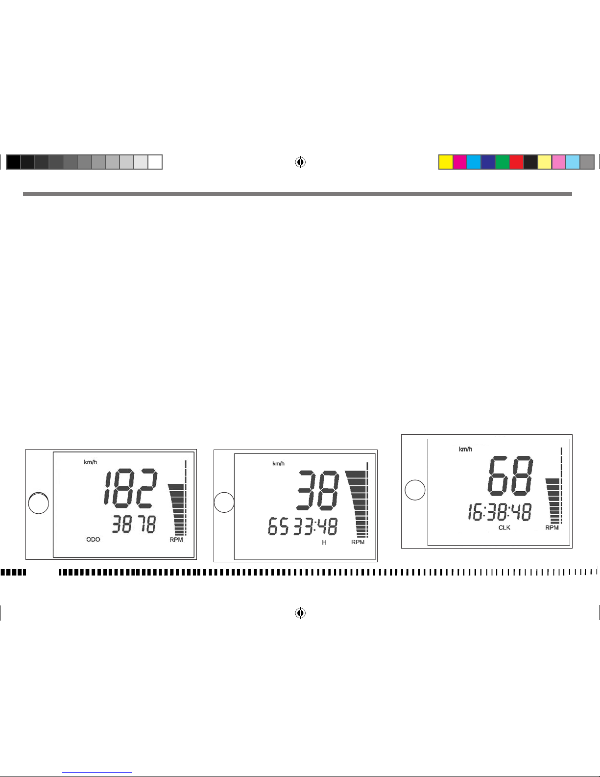
1- SPEED (kmh o mph) / ODO / RPM
(gura 1)
- SPEED: velocità del veicolo- Indicazione max: 299
kmh o 299 mph;
- ODO: odometro- Indicazione max: 99999 km;
- RPM: regime motore visualizzato sull’indicatore a
barre verticale.
Per passare da km a miles o da miles a km procedere nel modo seguente:
1) visualizzare la gura 1, porre la chiave di accensione in posizione OFF e premere il pulsante
SCROLL (A).
2) porre la chiave di accensione in posizione ON, tenendo premuto per 3 secondi il pulsante SCROLL
(A).
Per conferma dell’avvenuta conversione si attiveranno, per 3 secondi, “SET” ed i segmenti Miles e
mph oppure km e kmh; successivamente si tornerà
alla funzionalità standard della gura 1.
NOTA
Al termine dell’operazione descritta, il dato
ODO verrà convertito e tutti gli altri dati azzerati ( il CONTA H rimane invariato).
3- SPEED / CLOCK / RPM (gura 3)
- SPEED: velocità- Indicazione max: 299 kmh o 299
mph;
- CLOCK: orologio- Indicazione da 0:00 a 23:59:59 ( il
dato verrà perso al distacco della batteria).
Per regolare l’orologio, premere il pulsante SCROLL
(A) per più di 3 secondi per incrementare le ore; rilasciato il pulsante, dopo3 secondi è possibile incrementare i minuti;
- RPM: regime motore visualizzato sull’indicatore a
barre verticale.
2- SPEED / H / RPM (gura 2)
- SPEED: velocità- Indicazione max: 299 kmh o 299
mph;
- H: Indica le ore di funzionamento del motore (il
dato è salvato in memoria permanente ogni 10
minuti)
- Indicazione max: 9999:59;
- RPM: regime motore visualizzato sull’indicatore a
barre verticale.
Quick RS-SM_125_MY16_ed00_11-2016_CodA000P01895.indd 12 15/12/16 12:42
Page 17

4
5
6
IT - 13
IT
4- SPEED / TRIP 1 / RPM (gura 4)
- SPEED: velocità - indicazione max: 299 kmh o 299
mph
- TRIP 1: distanza - indicazione max: 999, 9 km (il
dato verrà perso al distacco della batteria).
L’azzeramento di STP 1 comporta anche quello dei
dati TRIP 1 e AVS 1.
Il TRIP 1 è attivo contestualmente a STP 1(*)
- RPM: regime motore visualizzato sull’indicatore a
barre verticale.
(*): vedere gura 5
5- SPEED / STP 1 / RPM (gura 5)
- SPEED: velocità - indicazione max: 299 kmh o 299
mph;
- STP 1: tempo di percorrenza km - mi.
- Indicazione da 0:00 a 23:59:59 ( il dato verrà perso al distacco della batteria).
Il contatore STP 1 si attiva premendo, a funzione visualizzata, il tasto pulsante SCROLL (A) per più di 3
secondi.
- premendo SCROLL (A) per più di tre secondi si av-
via il contatore;
- premendo SCROLL (A) per una sola volta si blocca
il contatore;
- premendo SCROLL (A) per una sola volta si azzera
il contatore;
.............................
e così di seguito
NOTA
dati STP 1 + dati TRIP 1 = AVS 1 (*).
- RPM: regime motore visualizzato sull’indicatore a
barre verticale.
(*): vedere gura 6
6- SPEED / AVS 1 / RPM (gura 6)
- SPEED: velocità - indicazione max: 299 kmh o 299
mph
- AVS 1: rappresenta la velocità media di percorrenza del veicolo, data una distanza (TRIP 1) ed un
tempo di percorrenza (STP 1)( il dato verrà perso
al distacco della batteria).
NOTA
L’azzeramento di STP 1 comporta anche quello dei
dati TRIP 1 e AVS 1.
- RPM: regime motore visualizzato sull’indicatore a
barre verticale.
Quick RS-SM_125_MY16_ed00_11-2016_CodA000P01895.indd 13 15/12/16 12:42
Page 18

A
7
8
9
10
IT - 14
7- SPEED / V MAX / RPM (gura 7)
- SPEED: velocità - indicazione max: 299 kmh o 299
mph;
- V MAX: indica la velocità MAX, in kmh o mph, raggiunta dal veicolo.
Indicazione max: 299 kmh o 299 mph. Per azzerare
V MAX, premere il pulsante SCROLL (A) per più di
3secondi;
- RPM: regime motore visualizzato sull’indicatore a
barre verticale.
8- SPEED / TRIP 2 / RPM (gura 8)
- SPEED: velocità - indicazione max: 299 kmh o 299
mph
-
TRIP 2: distanza - indicazione max: 999, 9 km / miles (il dato verrà perso al distacco della batteria)
.
Per azzerare il TRIP 2, premere il pulsante SCROLL (A)
per più di 3 secondi;
- RPM: regime motore visualizzato sull’indicatore a
barre verticale.
9- TRP 2 / CLOCK / RPM (gura 9)
- TRIP 2: distanza - indicazione max: 999, 9 km /
miles (il dato verrà perso al distacco della batte-
ria).
Per azzerare il TRIP 2, premere il pulsante SCROLL (A)
per più di 3 secondi;
- CLOCK: orologio - indicazione da 0:00 a 23:59:59 (
il dato verrà perso al distacco della batteria).
Per regolare l’orologio, premere il pulsante SCROLL
(A) per più di 3 secondi per incrementare le ore; rilasciato il pulsante, dopo 3 secondi è possibile incrementare i minuti;
- RPM: regime motore visualizzato sull’indicatore a
barre verticale.
10- SPEED /RPM (Indicazione numerica regime
motore) (gura 10)
- SPEED: velocità - indicazione max: 299 kmh o 299
mph
- RPM: regime motore visualizzato sull’indicatore a
barre verticale e dall’indicazione numerica.
Quick RS-SM_125_MY16_ed00_11-2016_CodA000P01895.indd 14 15/12/16 12:42
Page 19

1
7
2
3
4
5
6
IT - 15
IT
ARRESTO DEL MOTOCICLO E DEL MOTORE
- Chiudere completamente la manopola (1) del gas in
modo da far decelerare il motociclo.
- Frenare mentre si scalano le marce (per una forte
decelerazione, agire in modo deciso su leva e pedale dei freni).
NOTA
Tirando la leva (2) si frenerà con il freno anteriore;
premendo il pedale (3) si avrà una frenata combinata per cui il sistema ripartirà la frenata, sia sul
freno anteriore, sia sul freno posteriore.
- Una volta arrestato il motociclo, tirare la leva frizione (4) e porre la leva (5) del cambio in posizione
di folle.
- Ruotare la chiave di avviamento (6) in posizione “
” (posizione di estrazione chiave).
ARRESTO DEL MOTORE IN EMERGENZA
- Premere il pulsante rosso (7) per arrestare il motore; dopo l’utilizzo riportarlo nuovamente nella
posizione “estratta”.
Quick RS-SM_125_MY16_ed00_11-2016_CodA000P01895.indd 15 15/12/16 12:42
Page 20

1
2
1
IT - 16
Una volta arrestato il motociclo, porlo sul cavalletto
laterale.
CAVALLETTO LATERALE
Ogni motociclo è fornito di un cavalletto laterale (1).
ATTENZIONE*: Il cavalletto è progettato per
supportare il SOLO PESO DEL MOTOCICLO.
Non sedersi sul veicolo utilizzando il cavalletto come supporto; potrebbero verificarsi delle
rotture con conseguenti gravi lesioni personali.
ATTENZIONE*: Il motociclo DEVE essere posto
sul cavalletto laterale SOLO DOPO che il pilota
è sceso dal veicolo.
Una volta riportato il motociclo dalla posizione di appoggio sul terreno a quella verticale,
il pilota, con il piede sinistro, deve sollevare il
cavalletto dalla posizione abbassata alla posizione sollevata.
ATTENZIONE*: Sul motociclo è posizionato un
sensore (2) di sicurezza che permette l’avviamento della moto, con cavalletto abbassato e
marcia in folle.
Inserendo la marcia con cavalletto abbassato,
il motore si spegne.
BLOCCASTERZO
Il motociclo è fornito di un bloccasterzo (1) posto sul
lato destro del cannotto di sterzo.
Per bloccare lo sterzo, operare nel modo seguente:
girare il manubrio a sinistra, inserire la chiave nella serratura e girarla in senso antiorario. Spingerla
verso l’interno e,se necessario, girare il manubrio nei
due sensi. Girare la chiave in senso orario ed estrarla
dalla serratura.
Per sbloccare lo sterzo, operare inversamente.
Quick RS-SM_125_MY16_ed00_11-2016_CodA000P01895.indd 16 15/12/16 12:42
Page 21

4
2
M
1
P
D
1
A
B
3
IT - 17
IT
FUSIBILI
In caso di cattivo funzionamento dei fusibili, si potrebbero verificare inconvenienti al motociclo. Per
accedere ai tre fusibili (due da 15A ed uno da 20A)
procedere nel modo seguente:
Rimuovere la sella (1) dopo aver ruotato in senso antiorario il perno posteriore (2) di fissaggio.
Svitare le viti (3) e togliere il pannello laterale destro
(4).
Per evitare cortocircuiti, prima di operare sui fusibili,
porre l’interruttore di accensione in posizione OFF.
• Non utilizzare un fusibile di capacità diver-
sa da quella dell’originale.
M-20A
(guaina del cavo contraddistinta da scritta
“MAIN” o “M”):
12V sottochiave (tensione impianto), luci di posizione;
P-15A
(guaina del cavo contraddistinta da scritta “POW”
o “P”):
pompa carburante, bobina A.T., riscaldatore sonda
Lambda, iniettore;
D-15A
(guaina del cavo contraddistinta da scritta “DC” o
“D”):
elettroventola, stop posteriore, abbagliante, anabbagliante, indicatori di direzione, avvisatore acustico,
alimentazione cruscotto (visualizzazione funzioni strumento).
Quick RS-SM_125_MY16_ed00_11-2016_CodA000P01895.indd 17 15/12/16 12:42
Page 22

Quick RS-SM_125_MY16_ed00_11-2016_CodA000P01895.indd 18 15/12/16 12:42
Page 23

IT - 19
IT
Libretto di
garanzia e di servizio
Quick RS-SM_125_MY16_ed00_11-2016_CodA000P01895.indd 19 15/12/16 12:42
Page 24

IT - 20
IL CONTENUTO DELLA GARANZIA
La Sua nuova moto è garantita esente da difetti originari in conformità alla Direttiva 99/44 CE.
La garanzia consiste nella sostituzione o riparazione gratuita del veicolo o di componenti che abbiano
a manifestare, entro il suddetto termine, difetti di
fabbricazione o, comunque, difetti preesistenti alla
consegna veicolo.
La garanzia è valida solo se il vostro veicolo ha seguito il programma di manutenzione raccomandato
e se tutti i tagliandi sono stati correttamente timbrati.
Le ricordiamo che la garanzia non opera nel caso
di uso del veicolo in competizioni motociclistiche, in
quanto trattasi di uso diverso e non compatibile con
l’uso per il quale il suo veicolo è stato specificatamente progettato.
Si ricordi che, come richiesto dalla legge, questa garanzia è prestata direttamente dal Suo Concessionario SWM al quale La invitiamo a rivolgersi per ogni
necessità del caso.
Laddove il Suo Concessionario SWM non possa soddisfare le sue richieste in un tempo ragionevole ovvero questo fosse per Lei più comodo, La invitiamo a
rivolgersi ad un qualsiasi altro Concessionario SWM
che sarà lieto di porsi al suo servizio.
L’ATTIVAZIONE DELLA GARANZIA
Il suo veicolo è coperto da garanzia da difetti originari sin dal momento in cui Le viene consegnato dal
Suo Concessionario SWM .
Quando riceverà la sua SWM, La invitiamo a sottoscrivere, unitamente al Concessionario, il Certificato
di Consegna del veicolo che trova su questo manuale.
COSA FARE IN CASO DI RICHIESTA DI INTERVENTO IN GARANZIA
Nel caso in cui, nel periodo di validità della garanzia,
il Suo veicolo necessiti di un intervento straordinario di riparazione e/o sostituzione dipendente da un
difetto originario, Le consigliamo di rivolgersi immediatamente al Concessionario ove ha acquistato il
veicolo (il Suo Concessionario) descrivendogli il problema occorso e facendogli esaminare il veicolo.
Se l’intervento è reso necessario dall’avvenuto manifestarsi di un difetto originario, il Suo Concessionario
provvederà ad effettuare gratuitamente la riparazione o la sostituzione necessaria e nel minor tempo
possibile.
CONDIZIONI DI GARANZIA
Esclusioni
Sono esclusi dalla garanzia:
• I deterioramenti derivanti dal mancato rispetto
del piano di manutenzione periodica prescritta
da SWM.
• I veicoli le cui riparazioni sono state effettuate
con ricambi non conformi all’originale.
• I veicoli per cui non è stato eseguito il piano di
manutenzione periodica o per i quali i tagliandi
non sono stati debitamente timbrati
• I veicoli utilizzati per competizioni/noleggio/uso
gravoso fuoristrada.
Parti di consumo ed usura:
La garanzia non copre l’usura ed il deterioramento
normale determinata dall’uso del veicolo per i seguenti pezzi:
• Candele.
• Catena di distribuzione.
• Pastiglie e dischi freno.
• Dischi e masse frizione.
• Pneumatici.
• Lampade e fusibili.
• Cavi di trasmissione e di comando.
• Tubi e tutte le altre parti in gomma.
• Cuscinetti.
• Filtro aria e benzina.
• Catena ed ingranaggi trasmissione secondaria.
Quick RS-SM_125_MY16_ed00_11-2016_CodA000P01895.indd 20 15/12/16 12:42
Page 25

IT - 21
IT
Lubrificanti
La garanzia non copre i liquidi: olio ,grasso, acido
batteria e liquido di raffreddamento.
Limitazioni
Per tutti i veicoli: la garanzia della BATTERIA, della
SELLA e delle PLASTICHE è limitata a 6 mesi.
• La garanzia non copre i costi di manutenzione
e di revisione, nè il costo dei pezzi necessari a
queste operazioni.
• La garanzia non copre le spese conseguenti alla
domanda di garanzia quali: spese addizionali
per le comunicazioni, l’eventuale vitto ed alloggio, nè altre spese derivate come compensazioni per il tempo perduto, perdite commericiali,
spese di noleggio di veicolo sostitutivo, spese di
trasporto.
Nota importante per la validità della garanzia:
• Il carnet di garanzia deve essere conservato con
cura e deve essere presentato al concessionario
ufficiale SWM ad ogni intervento.
• I tagliandi di revisione devono essere compilati
dal concessionario che ha effettuato l’intervento.
• La garanzia può essere trasferita ai proprietari
successivi fino alla sua scadenza.
• In caso di passaggio di proprietà, utilizzare il tagliando apposito presente in questo libretto.
• Il produttore si riserva il diritto di apportare delle modifiche e/o migliorie su tutti i suoi modelli
senza l’obbligo di effettuare queste modifiche
sui veicoli già in circolazione.
Quick RS-SM_125_MY16_ed00_11-2016_CodA000P01895.indd 21 15/12/16 12:42
Page 26

IT - 22
Quick RS-SM_125_MY16_ed00_11-2016_CodA000P01895.indd 22 15/12/16 12:42
Page 27

!
IT - 23
IT
CERTIFICATO DI CONSEGNA
Data:
N° Telaio:
Modello:
N° Motore:
Il motociclo è stato preparato per la consegna eseguendo tutti i controlli e le operazioni di preconsegna previste da SWM MOTORCYCLES S.R.L. e completato di tutti gli eventuali accessori opzionali richiesti dal Cliente.
Al Cliente è stato consegnato il presente Libretto di Garanzia ed il Manuale di Uso e Manutenzione e sono stati
illustrati i principali dispositivi di guida in dotazione al veicolo.
Timbro e firma del concessionario
CLIENTE
Nome:
_________________________________________
Cognome:
_____________________________________
Indirizzo:
______________________________________
Città:
__________________________________________
CAP:
__________________________________________
Recapito telefonico:
___________________________
Dichiaro di ricevere oggi il motociclo sopra indicato
completo e conforme alle mie aspettative, nonché
dichiaro di ricevere il presente Libretto di Garanzia
ed il Manuale di Uso e Manutenzione. Autorizzo
SWM MOTORCYCLES S.R.L. al trattamento dei miei
dati personali ai fini della fornitura del Servizio di Assistenza ai sensi della Legge 675/1996 e successive
modifiche.
Firma del cliente
_______________________________________________
Copia per SWM MOTORCYCLES S.R.L.
L’organizzazione ufficiale di vendita e la società SWM MOTORCYCLES S.R.L., dichiarano che il trattamento dei
dati personali dell’acquirente, con riferimento alla Legge n° 675 del 1996 e successive modifiche, può avvenire
anche senza necessità del consenso del Cliente, in attuazione dell’obbligo di fornitura del Servizio di Assistenza.
Quick RS-SM_125_MY16_ed00_11-2016_CodA000P01895.indd 23 15/12/16 12:42
Page 28
IT - 24
Quick RS-SM_125_MY16_ed00_11-2016_CodA000P01895.indd 24 15/12/16 12:42
Page 29

!
IT - 25
IT
COMUNICAZIONE DI PASSAGGIO DI PROPRIETÀ
Data: Km:
N° Telaio:
Modello:
N° Motore:
Il sottoscritto:
_______________________________________________________________________________________
Nome:
______________________________________________________________________________________________
Cognome:
__________________________________________________________________________________________
Indirizzo:
___________________________________________________________________________________________
Città:
______________________________________________________________________
CAP:
__________________
Recapito telefonico:
_______________________________________________________________________________
__________________________________________________________________________________________________
Inviare in busta chiusa a: SWM MOTORCYCLES S.R.L. Servizio Assistenza Tecnica, Via Nino Bixio, 8 - 21024
Biandronno (VA) - Italy
L’organizzazione ufficiale di vendita e la società SWM MOTORCYCLES S.R.L., dichiarano che il trattamento dei
dati personali dell’acquirente, con riferimento alla Legge n° 675 del 1996 e successive modifiche, può avvenire
anche senza necessità del consenso del Cliente, in attuazione dell’obbligo di fornitura del Servizio di Assistenza.
CLIENTE
Comunica a SWM MOTORCYCLES S.R.L. che in data
odierna ha ceduto la proprietà del veicolo sopraindicato al Signor:
Nome:
_________________________________________
Cognome:
_____________________________________
Indirizzo:
______________________________________
Città:
__________________________________________
CAP:
__________________________________________
Recapito telefonico:
____________________________
consegnandogli il presente Libretto di Garanzia ed il
Manuale di Uso e Manutenzione in dotazione.
Copia per SWM MOTORCYCLES S.R.L.
Quick RS-SM_125_MY16_ed00_11-2016_CodA000P01895.indd 25 15/12/16 12:42
Page 30

IT - 26
Quick RS-SM_125_MY16_ed00_11-2016_CodA000P01895.indd 26 15/12/16 12:42
Page 31

IT - 27
IT
TAGLIANDO DATA Km
Firma del Timbro del
Cliente
Concessionario
TAGLIANDO DATA Km
Firma del Timbro del
Cliente
Concessionario
TAGLIANDO DATA Km
Firma del Timbro del
Cliente
Concessionario
TAGLIANDO DATA Km
Firma del Timbro del
Cliente
Concessionario
TAGLIANDO DATA Km
Firma del Timbro del
Cliente
Concessionario
TAGLIANDO DATA Km
Firma del Timbro del
Cliente
Concessionario
TAGLIANDO DATA Km
Firma del Timbro del
Cliente
Concessionario
TAGLIANDO DATA Km
Firma del Timbro del
Cliente
Concessionario
TAGLIANDO DATA Km
Firma del Timbro del
Cliente
Concessionario
Spazio per la conservazione della documentazione fiscale comprovante l’avvenuta esecuzione dei tagliandi di manutenzione previsti.
FISSARE con una graffetta o una pinzatrice la Ricevuta Fiscale o Scontrino Fiscale che attestano l’avvenuta esecuzione dei tagliandi di manutenzione.
TAGLIANDO DATA Km
Firma del Timbro del
Cliente
Concessionario
Quick RS-SM_125_MY16_ed00_11-2016_CodA000P01895.indd 27 15/12/16 12:42
Page 32

Quick RS-SM_125_MY16_ed00_11-2016_CodA000P01895.indd 28 15/12/16 12:42
Page 33

EN
EN - 1
ENGLISH
Quick RS-SM_125_MY16_ed00_11-2016_CodA000P01895.indd 1 15/12/16 12:40
Page 34

EN - 2
SWM MOTORCYCLES S.R.L. Thank you for choos-
ing a SWM and would like to remind you that to
continually deliver top performance in full safety,
your SWM requires regular maintenance by the
After Sales Service of the authorised SWM dealer
network.
Our highly experience technicians have worked to
create a top quality vehicle that will ensure you enjoyment and safety long-term.
Nevertheless, we need your collaboration. Carefully
read this Use and Maintenance Manual downloadable from the site www.swm-motorcycles.it after
registration and have the routine and extraordinary maintenance as well as all the technical operations carried out by specialised personnel of the
official SWM Dealer Network.
TABLE OF CONTENTS
Scheduled maintenance
programme ..............................page 3
Technical data ...........................page 4
Table for lubrication, supplies ..............page 5
Preliminary controls......................page 6
Control location ..........................page 8
Instructions for motorcycle use ...........page 9
Starting the motor........................page 9
R.H. handlebar commutator ...............page 9
Left handlebar switch....................page 10
Digital instrument, warning lights..........page 11
Stopping the motorcycle and the engine...page 15
Stopping the motor in an emergency......page 15
Sidestand...............................page 16
Steering lock ............................page 16
Fuses...................................page 17
Service booklet..........................page 19
Warranty ...............................page 20
Quick RS-SM_125_MY16_ed00_11-2016_CodA000P01895.indd 2 15/12/16 12:40
Page 35

EN
EN - 3
MAINTENANCE TABLE
This Quick Manual contains the basic instructions for proper use of the motorcycle. The complete documentation is contained in the Use and Maintenance Manual downloadable from the site www.swm-motorcycles.
it after registration.
USE AND MAINTENANCE MANUAL
THE SCHEDULED MAINTENANCE PROGRAMME
SWM MOTORCYCLES S.R.L. has drawn up a scheduled maintenance programme and the pre-delivery
operations to guarantee that your vehicle performs
at the maximum levels of efficiency, and safety.
You will find the scheduled maintenance plan designed for your motorcycle in the Use and Maintenance Manual downloadable from the site www.
swm-motorcycles.it after registration. It is essential
that you have your bike serviced at the stated intervals in order to maintain the vehicle’s safety and
reliability levels.
We remind you that, should your vehicle experience
problems as a result of inadequate or incorrect servicing, the repair of the vehicle will not be covered
by warranty. SWM MOTORCYCLES S.R.L. may not
be held liable for possible injuries suffered by the
user of the vehicle as a result of said breakdowns or
mechanical failures. All the maintenance Coupons,
including the initial ones, are to be paid for, both for
materials and for labour. On the contrary, the predelivery operations, as set out in the maintenance
plan are carried out at the Dealer’s free of charge.
Any service on the vehicle, both in case of Guarantee Servicing and of any sort of repairs, settings, replacements or other, must be carried out at the approved SWM Dealers’ workshops, according to the
methods established by SWM MOTORCYCLES S.R.L.
Only the fiscal receipt (invoice or till receipt) that
will be provided by the Dealer on completion of the
scheduled maintenance work provides proof that
the service has indeed been carried out.
RS 125 R
SM 125 R
SCHEDULE FOR PERIODIC MAINTENANCE
SERVICE SERVICE SERVICE SERVICE SERVICE
1.000 km
621,37 mi.
5.000 km
3106,85 mi.
10.000 km
6213,71 mi.
15.000 km
9320,56 mi.
20.000 km
12427,42 mi.
Quick RS-SM_125_MY16_ed00_11-2016_CodA000P01895.indd 3 15/12/16 12:40
Page 36

EN - 4
TECHNICAL DATA
ENGINE
Type .....................single cylinder, 4 stroke
Cooling liquid with electric fan
Water radiators .............................n° 2
Bore .................................... 2,28 in.
Stroke ...................................1,85 in.
Displacement ...........................7,61 in3.
Compression ratio ..........................12,8:1
Starting .................................electric
TIMING SYSTEM
Type ..........double overhead camshaft; 4 valve
Intake ..........................0,002 ÷ 0,004 in.
Exhaust ........................0,006 ÷ 0,008 in.
LUBRICATION
Type ...................dry sump with lobe pump
and cartridge filter
IGNITION
Type ..............Electronic, inductive discharge,
with adjustable advance (digital control)
Spark plug type ......................“NGK” CR8E
Spark plug gap ..........................0,031 in.
FUEL SYSTEM
Type .....................Electronic injection feed
Throttle body ...........................ø 1,26 in.
PRIMARY DRIVE
Drive pinion gear- Clutch ring gear .......Z 20- Z 67
Transmission ratio ..........................3,35
CLUTCH
Type .........................multidisc in oil bath
with mechanical control
No. of conducting discs .........................5
No. of conducted discs ..........................4
TRANSMISSION
Type ...................constant mesh gear type
No. of gears ..................................6
Transmission ratio
1st gear ...........................2,833 (z 34/12)
2nd gear ..........................2,066 (z 31/15)
3rd gear ...........................1,555 (z 28/18)
4th gear ...........................1,238 (z 26/21)
5 th gear ..........................1,045 (z 23/22)
6 th gear ......................... 0,916 (z 22/24)
SECONDARY DRIVE
Gearbox outlet pinion - rear crown
RS .....................................Z 14- Z 58
SM ...................................Z 14- Z 54
Transmission ratio
RS ........................................ 4,142
SM .......................................3,857
TRANSMISSION CHAINE
Brand and type ............ “REGINA” 126RSHB-12.7
FRAME
Type ..................single beam, double cradle
in high-strength steel tubes;
rear frame in steel
FRONT SUSPENSION
Type .........”Upside-down” telescopic hydraulic
front fork with advanced axle ;
stanchions tubes Ø 1,61 in.
Legs axis stroke .........................9,84 in.
REAR SUSPENSION
Type ...................progressive “SOFT DAMP”
with hydraulic single shock absorber
Wheel stroke ............................9,84 in.
FRONT BRAKE
Type .......fixed disc RS: Ø 10,23 in. - SM: Ø 11,81 in.
with hydraulic control and floating caliper
REAR BRAKE
Type .................floating disc, Ø 8,66 in. with
hydraulic control and floating caliper
RIMS
Front (RS) ....................in light alloy: 1,6x21”
Front (SM) .................. in light alloy: 2,75x17”
Quick RS-SM_125_MY16_ed00_11-2016_CodA000P01895.indd 4 15/12/16 12:40
Page 37

EN
EN - 5
Rear (RS) ....................in light alloy: 2,15x18”
Rear (SM) ..................in light alloy 4,00x17”
TIRES
Type ....................................KENDA
RS .............................80/90-21” K774F
SM ...................................110/70-17”
Rear
Type ....................................KENDA
RS .............................. 110/80-18” K774
SM ..................................140/70-17”
Cold tire pressure RS
Front
Rider only ............................1,2 kg/cm
2
Rider and passenger ..................1,5 kg/cm
2
Rear
Rider only ............................1,5 kg/cm2
Rider and passenger ..................1,8 kg/cm
2
Cold tire pressure SM
Front
Rider only ............................1,8 kg/cm2
Rider and passenger ..................2,0 kg/cm
2
Rear
Rider only ............................2,0 kg/cm2
Rider and passenger ..................2,2 kg/cm
2
DIMENSION, WEIGHT, CAPACITY
Wheelbase
RS .....................................57,67 in.
SM ....................................59,05 in.
Overall length
RS .....................................88,03 in.
SM .....................................82,91 in.
Overall width ...........................32,28 in.
Overall height
RS .....................................48,42 in.
SM ....................................45,86 in.
Saddle height
RS .....................................37,40 in.
SM ....................................35,98 in.
Minimum ground clearance
RS ......................................12,59 in.
SM .....................................10,82 in.
Trail
RS .......................................4,37 in.
SM .....................................3,26 in.
Dry weight
RS ....................................257,94 lb.
SM ...................................264,55 lb.
Fuel tank capacity .......1.58 Imp. Gall./ 1.9 U.S. Gall
Coolant capacity ..............0,24÷0,28 Imp. Gall.;
0,29÷0,34 U.S. Gall
Transmission oil
Oil and oil filter replacement ........0,29 Imp. Gall.
0,35 U.S. Gall
Oil replacement ....................0,27 Imp. Gall.
0,33 U.S. Gall
Homologation ............................EURO 4
TABLE FOR LUBRICATION, SUPPLIES
Engine, gearbox and primary drive lubricating oil
MOTUL 5100 TECHNOSYNTHESE 10W50
Engine coolant
MOTUL MOTOCOOL EXPERT
Brake system fluid
MOTUL DOT 3
Grease lubrication
MOTUL GREASE 100
Final drive chain lubrication
MOTUL CHAIN LUBE
Front fork oil
MOTUL FORK OIL LIGHT 5W
Electric contact protection
MOTUL EZ LUBE
Quick RS-SM_125_MY16_ed00_11-2016_CodA000P01895.indd 5 15/12/16 12:40
Page 38

1
MAX
MIN
1
2
„A“
2
=
2/3
cm.
=
0,78 / 1,81 in.
3
EN - 6
PRELIMINARY CONTROLS
A. Engine-transmission oil level
Keeping the motorbike level and upright, check the
oil level through the inspection (1) window on the
right crankcase. Check that the level is in the middle of the sightglass “A” between the MIN and MAX
notch.
To fill up, remove the filler cap (2).
B. Fuel level
Check the level in the tank, top up as needed.
C. Coolant level
Check level (1) in right-hand radiator when engine
is cold (place the motorbike fully upright). The coolant must be 10mm above the parts and the level
may not be more than 2-3cm from the bottom of
the recovery reservoir (2) located in front of the rear
shock absorber. The radiator cap (3) is provided with
two locking positions: the first one is for prior discharge of pressure in the cooling system.
WARNING:
Avoid removing radiator cap when engine
is hot, as coolant may spout out and cause
scalding.
Quick RS-SM_125_MY16_ed00_11-2016_CodA000P01895.indd 6 15/12/16 12:40
Page 39

4
1
MIN
1
MIN
EN
EN - 7
WARNING:
Remember that the cooling fan (4) can start
up even when the start switch is turned to
the OFF position; always work, therefore, at a
safe distance from the fan blades.
D. Brake fluid level
Front brake
The fluid level in the pump reservoir may never drop
below the MIN notch visible on the sightglass (1) on
the rear of the pump body.
Rear brake
The fluid level in the pump reservoir may never drop
below the MIN notch visible on the sightglass (1) on
the pump body.
E. Electrical system
Start the motor, as instructed in the section “Instructions for using the motorcycle”, and check that
the lights, brake light, indicators, warning lights on
the dashboard and horn all work correctly.
F. Tyre pressure
Check the tyre pressure, which must correspond to
the pressure values provided in the section “Technical data”.
Quick RS-SM_125_MY16_ed00_11-2016_CodA000P01895.indd 7 15/12/16 12:40
Page 40

3
1
2
7
6
5
4
10
8
9
EN - 8
1. Front brake lever
2. Throttle grip
3. Combined braking control pedal
4. Right handlebar switch
5. Digital instrument
6. Ignition switch
CONTROL LOCATION
7. Left handlebar switch
8. Clutch control lever
9. Gearbox control pedal (to engage first gear, push
the lever down, for other gears push it upwards.
The “idle” gear is between the first and second
gear)
10. ENGINE STOP button (emergency stopping of motor)
Quick RS-SM_125_MY16_ed00_11-2016_CodA000P01895.indd 8 15/12/16 12:40
Page 41

1
N
5
3
4
2
1
2
EN
EN - 9
INSTRUCTIONS FOR USING THE MOTORCYCLE
STARTING THE ENGINE
- set ignition key (1) in “
” position (the buzz
that you hear when you turn the key to “
” is
caused by the fuel pump which puts the feeding
system under pressure);
- pull the clutch lever (2);
- shift the gear pedal (3) into neutral position;
- Check that the button (4) is in the out position
and press it, followed by the start button (5).
NOTE
When starting with an already warmed up engine
DO NOT USE the starter. When a cold engine has
just been started, do not increase revs, to ensure
an adequate oil warm-up and circulation.
NOTE
A safety switch is set on the clutch lever support.
This switch allows you to ONLY start the engine
with the gearbox idle, or with the gear engaged
and the clutch lever pulled.
With the stand lowered, the bike can only be started with the gear in neutral.
RIGHT HAND HANDLEBAR SWITCH
The right hand handlebar switch contains the following commands:
1) Engine start button
2) Emergency switch to shut off engine.
Quick RS-SM_125_MY16_ed00_11-2016_CodA000P01895.indd 9 15/12/16 12:40
Page 42

1
2
3
4
C
D
A
B
B
C
EN - 10
LEFT HAND HANDLEBAR SWITCH
The left hand handlebar switch contains the following commands:
Headlamp (A)
1) High beam flasher (automatic turn-off)
2) High beam switch
Low beam switch
Indicators (turning signals) (B), (C)
3) Left turn indicator (automatic return)
Right turn indicator (automatic return)
To deactivate the indicators, press the control
level after it has returned to centre.
4) Horn (D)
IMPORTANT NOTE IN CASE OF COLD START AT
LOW TEMPERATURES
It is recommended to briefly warm up at idle speed
until you get a normal engine response to the accelerator openings.
In this way, the oil can reach all the surface
requiring lubrication and the coolant can reach the
temperature required for correct engine function.
Avoid warming up the engine for an excessive
period of time.
Quick RS-SM_125_MY16_ed00_11-2016_CodA000P01895.indd 10 15/12/16 12:40
Page 43

1
4
5
3
2
A
EN
EN - 11
DIGITAL INSTRUMENT, WARNING LIGHTS
The motorcycle is fitted with a digital instrument
on which 5 warning lights are also displayed: high
beam lights, low beam lights (with display lighting),
turning indicators, neutral gear and fuel reserve.
1- BLUE warning light “HIGH BEAM”
2- ORANGE warning light “Engine fault”
3- GREEN warning light “TURNING INDICATORS”
4- GREEN warning light “NEUTRAL GEAR”
5- ORANGE warning light “FUEL RESERVE”
NOTE:
- After turning the key to ON, the instrument
starts a function test. When the test is complete,
the instrument shows the last function set.
- When the engine is turned o, the instrument
does not show any functions.
- To select instrument functions and reset functions, use the SCROLL button (A)
- The functions, which can be selected in order are
as follows:
1- SPEED / ODO
2- SPEED / H
3- SPEED / CLOCK
4- SPEED / TRIP 1
5- SPEED / STP 1
6- SPEED / AVS 1
7- SPEED / SPEED MAX
8- SPEED / TRIP 2
9- TRP 2 / CLOCK
10- SPEED / RPM (engine r.p.m. numerical value)
.................
NOTE
The RPM function seen on the vertical bar indicator
is ALWAYS active.
*IMPORTANT:
If the “Engine fault” warning light (2) comes on during use, it indicates that there is an engine malfunction and you therefore have to contact an SWM
dealer as soon as possible.
Quick RS-SM_125_MY16_ed00_11-2016_CodA000P01895.indd 11 15/12/16 12:40
Page 44
1
2
3
EN - 12
1- SPEED (kmh or mph) / ODO / RPM (figure 1)
- SPEED: 299 kmh or 299 mph;
- ODO: odometer- maximum value: 99999 km;
- RPM: engine r.p.m. shown on the vertical bar.
To replace kilometers with miles or miles with kilometers proceed as follows:
1) set to gure 1, place the ignition key in the OFF
position and push the knob SCROLL (A);
2) place the ignition key in the ON position while
pressing the SCROLL wheel for 3 seconds (A)
To confirm the conversion, the “SET” and the Miles
and mph or km and kmh segment will activate for
3 seconds; afterwards the standard function in Fig.1
will reappear.
NOTE
After the previously described operation, the
ODO setting will be converted and all other
data reset (the H Counteris unchanged).
3- SPEED / CLOCK / RPM (figure 3)
- SPEED: 299 kmh or 299mph;
- CLOCK: Clock- reading from 0:00 to 23:59:59 (the
data will be lost after detaching battery);
To set clock, press the SCROLL button (A) for 3 seconds or more to increase the hour; release button
and after 3 seconds the minutes can be increased;
- RPM: engine r.p.m. shown on the vertical bar indicator.
2- SPEED / H / RPM (figure 2)
- SPEED: 299 kmh or 299 mph;
- H: shows the running hours of the engine (data
are saved in permanent memory every 10 minutes). Maximum value: 9999:59;
- RPM: engine r.p.m. shown on the vertical bar indicator.
Quick RS-SM_125_MY16_ed00_11-2016_CodA000P01895.indd 12 15/12/16 12:40
Page 45

4
5
6
EN
EN - 13
4- SPEED / TRIP 1 / RPM (figure 4)
- SPEED: 299 kmh or 299mph;
- TRIP 1: distance - maximum value: 999.9 km (the
data will be lost after detaching battery).
If the STP 1 is set to zero, the functions TRIP 1 and
AVS1 will also be set to zero.
The function TRIP 1 is ON together with the
function STP 1 (*).
- RPM: engine r.p.m. shown on the vertical bar indicator.
(*): see gure 5
5- SPEED / STP 1 / RPM (figure 5)
- SPEED: 299 kmh or 299mph;
- STP 1: miles/kilometers covered time
- Reading from 0:00 to 23:59:59 (the data will be
lost after detaching battery).
To activate the function STP 1, push the knob SCROLL
(A) for more than 3 seconds.
- pressing SCROLL (A) for more than three seconds,
the counter starts;
- pressing SCROLL (A) once only, the counter stops;
- pressing SCROLL (A) once only, the counter resets;
.............................
and so on
NOTE
STP 1 data + TRIP 1 data = AVS 1 (*).
- RPM: engine speed seen on the vertical bar indicator.
(*): see figure 6
6- SPEED / AVS 1 / RPM (figure 6)
- SPEED: 299 kmh or 299 mph;
- AVS 1: shows the average speed for vehicle coverage, distance data (TRIP 1) and covered time
(STP1) (the data will be lost after detaching battery).
NOTE
Resetting the STP 1 also resets the TRIP 1 and AVS
1 data.
- RPM: engine r.p.m. shown on the vertical bar indicator.
Quick RS-SM_125_MY16_ed00_11-2016_CodA000P01895.indd 13 15/12/16 12:40
Page 46

A
7
8
9
10
EN - 14
7- SPEED / V MAX / RPM (figure 7)
- SPEED: m 299 kmh or 299 mph;
- V MAX: Shows the maximum speed reached by
the vehicle, in kmh or mph.
Maximum value: 299 kmh or 299 mph. To set to zero
V MAX, push the knob SCROLL (A) for more than 3
seconds;
- RPM: engine r.p.m. shown on the vertical bar indicator.
8- SPEED / TRIP 2 / RPM (figure 8)
- SPEED: 299 kmh or 299 mph;
- TRIP 2: distance - maximum value: 999.9 km/
miles (the data will be lost after detaching battery);
To set TRIP 2 to zero, push the knob SCROLL (A) for
more than 3 seconds;
- RPM: engine r.p.m. shown on the vertical bar indicator.
9- TRP 2 / CLOCK / RPM (figure 9)
- TRIP 2: distance - Max value: 999.9 km / miles
(the data will be lost after detaching battery).
To set TRIP 2 to zero, push the knob SCROLL (A) for
more than 3 seconds;
- CLOCK: Clock - reading from 0:00 to 23:59:59 (the
data will be lost after detaching battery).
To reset the clock, push the knob SCROLL (A) for
more than 3 seconds in order to increase the hours;
release the knob then, after 3 seconds, it is possible
to increase the minutes;
- RPM: engine r.p.m. shown on the vertical bar indicator.
10- SPEED /RPM (engine r.p.m. numerical value) (figure 10)
- SPEED: 299 kmh or 299 mph;
- RPM: engine r.p.m.; both vertical bar indicator
and numerical value are on.
Quick RS-SM_125_MY16_ed00_11-2016_CodA000P01895.indd 14 15/12/16 12:40
Page 47

1
7
2
3
4
5
6
EN
EN - 15
STOPPING THE MOTORCYCLE AND THE ENGINE
- Close the throttle (1) completely so that the engine
will help slow down the motorcycle.
- Brake while downshifting (for strong deceleration,
act decisively on the brake pedal lever).
NOTE
Pulling the lever (2), you brake with the front
brake; depressing the pedal (3), you have combined braking so the system will restart braking
on both the front and the rear brake.
- When stopped, pull the clutch lever (4) and shift
gear lever (5) into the neutral position
- Turn the ignition key (6) to the “
” position (po-
sition for removing key).
STOPPING THE MOTOR IN AN EMERGENCY
- Press the red button (7) to stop the motor; after
use, bring it back to the “out” position.
When the bike is off, place it on its side stand.
Quick RS-SM_125_MY16_ed00_11-2016_CodA000P01895.indd 15 15/12/16 12:40
Page 48

1
2
1
EN - 16
SIDESTAND
A kickstand (1) is supplied with every motorcycle.
WARNING*: The stand is designed to support
the weight of the MOTORCYCLE ONLY. Do not
sit on the motorcycle using the stand for support as this could cause structural failure to
the stand and could cause serious bodily injury.
WARNING*:
The motorcycle must ONLY be stood on its
kickstand AFTER the rider has dismounted.
Once the motorbike has been brought from
its rest position on the ground into vertical position, the driver has to raise the stand from
the lowered to the raised position with his left
foot.
WARNING*: A safety sensor (2) is fitted on the
motorbike, which allows starting it with the
stand lowered and the gear in neutral.
If a gear is engaged with the stand lowered,
the engine turns off.
STEERING LOCK
The motorcycle is equipped with a steering lock (1)
on the R.H. side of the steering head tube.
To lock it, procede as follows:
turn the handlebar leftwards, place the key in lock
and turn counterclockwise. Push the key inwards (if
necessary, turn to and from). Turn the key clockwise
and remove it from the lock.
To unlock the steering lock, reverse the above procedure.
Quick RS-SM_125_MY16_ed00_11-2016_CodA000P01895.indd 16 15/12/16 12:40
Page 49

4
2
M
1
P
D
1
A
B
3
EN
EN - 17
FUSES
Fuse malfunction could cause problems for the motorcycle. To access the three fuses (two 15A and one
20A) proceed as follows:
Remove the saddle (1) after turning the rear fastening pin (2) anticlockwise.
Undo the screws (3) and remove the R.H. side panel
(4).
To prevent short circuits, turn the On/Off switch to
OFF, BEFORE working on the fuses.
• Do not use fuses with a different capacity
from the original one.
M-20A (cable sheath with
“MAIN” or
“M” written on
it):
12V locked up (system voltage), position lights;
P-15A (cable sheath with
“POW” or
“P” written on it):
Fuel pump, HV coil, Lambda probe heater, injector;
D-15A (cable sheath with “DC” or “D” written on it):
heater fan, rear stop, high beam, low beam, directional signals, horn, dashboard power (instrument
function viewing).
Quick RS-SM_125_MY16_ed00_11-2016_CodA000P01895.indd 17 15/12/16 12:40
Page 50

Quick RS-SM_125_MY16_ed00_11-2016_CodA000P01895.indd 18 15/12/16 12:40
Page 51

EN
EN - 19
Warranty and
service booklet
Quick RS-SM_125_MY16_ed00_11-2016_CodA000P01895.indd 19 15/12/16 12:40
Page 52

EN - 20
THE CONTENT OF THE WARRANTY
Your new bike is guaranteed free from original defects in compliance with EC Rule 99/44.
The warranty consists of replacing or repairing the
vehicle or components which may show manufacturing defects or defects that existed before delivery to the owner, all free of charge.
The warranty is valid only if your vehicle has been
subjected to the recommended maintenance programme and if all the service coupons have correctly been stamped.
We remind you that the warranty does not apply
in the event that the vehicle is driven in motorbike
races, as this is a use that differs and is incompatible with the use for which your vehicle has been
specifically developed.
Please remember that, as per law requirements,
the warranty in question is provided directly by
your SWM dealer, who you should always contact
for any needs.
If your SWM Dealer could not fulfil your needs in a
reasonable time or should it be more convenient to
you, we invite you to ask at any other SWM Dealer,
who will be pleased to put himself at your service.
THE ACTIVATION OF THE WARRANTY
Your vehicle is covered by warranty against original defects from the time of delivery to you by your
SWM Dealer.
When you receive your SWM, please sign together
with the dealer the vehicle Delivery Certificate included in this manual.
WHAT TO DO IN THE EVENT A REPAIR IS REQUIRED UNDER WARRANTY
In the unlikely event that your motorcycle requires
an unscheduled repair and/or replacement as a result of an original defect during the warranty period, we advise you to contact the Dealer where you
bought the motorcycle at once, explain the problem
that has arisen and allow him to inspect the motorcycle.
We remind you to bring this Handbook with you, so
that the Dealer may verify the delivery date of the
vehicle.
Should any repairs be required due to an original
or manufacturing defect, your Dealer will repair or
replace the part free of charge, in the shortest possible time.
CONDITIONS OF WARRANTY
Exclusions
The warranty does not cover:
• Deterioration resulting from failure to comply
with the periodic maintenance plan prescribed
by SWM.
• Vehicles repaired using non-original spare parts.
• Vehicles that were not subjected to the periodic
maintenance plan or for which the service coupons have not duly been stamped.
• Vehicles used for competitions/rental/off-road
heavy duty.
Consumables and parts subject to wear:
The warranty does not cover wear and normal deterioration from use of the vehicle for the following
parts:
• Spark plugs.
• Transmission chain.
• Brake pads and discs.
• Clutch discs and bodies.
• Tyres.
• Bulbs and fuses.
• Transmission and drive cables.
• Tubes and all other rubber parts.
• Bearings.
• Air and fuel filters.
• Secondary transmission chain and gears.
Quick RS-SM_125_MY16_ed00_11-2016_CodA000P01895.indd 20 15/12/16 12:40
Page 53

EN
EN - 21
Lubricants
The warranty does not cover fluids: oil, grease, battery acid and coolant.
Limitations
For all vehicles: the warranty on the BATTERY, SADDLE and PLASTIC PARTS is limited to 6 months.
• The warranty does not cover the maintenance
and service costs nor the cost of the parts required for these operations.
• The warranty does not cover expenses resulting from filing a warranty claim: additional
expenses for communications, any board and
lodging nor other related expenses, such as
compensation for lost time, commercial losses,
replacement vehicle rental expenses, transport
expenses.
Important note for validity of the warranty:
• The warranty booklet must be carefully kept
and presented to the official SWM dealer every
time the vehicle is brought in for service
• The service coupons must be filled in by the dealer that serviced the vehicle.
• The warranty may be transferred to subsequent owners until its expiry.
• In the event of change of ownership, use the
dedicated coupon included in the warranty booklet.
• The manufacturer reserves the right to make
modifications and/or improvements to all its
models without any obligation to make such
modifications on vehicles already in circulation.
Quick RS-SM_125_MY16_ed00_11-2016_CodA000P01895.indd 21 15/12/16 12:40
Page 54

EN - 22
Quick RS-SM_125_MY16_ed00_11-2016_CodA000P01895.indd 22 15/12/16 12:40
Page 55

!
EN
EN - 23
DELIVERY CERTIFICATE
Date:
Frame no.:
Model:
Engine no.:
The motorcycle has been made ready for delivery by performing all of the checks and pre-delivery actions as
provided for by SWM MOTORCYCLES S.R.L., and fitted out with all the possible optional parts as requested
by the Buyer.
The Buyer has been provided with this Warranty Booklet and the Use and Maintenance Manual and has received an explanation of the main drive system parts that the vehicle has been fitted with.
Dealer’s stamp and signature
CUSTOMER
Name:
__________________________________________
Surname:
_______________________________________
Address:
_______________________________________
Town or City:
___________________________________
Postal Code:
____________________________________
Telephone no:
___________________________________
I hereby declare that I have today accepted delivery
of the motorcycle as described above, equipped and
fully compliant with my expectations. I also declare
that I have received the herein Warranty Booklet
and Use and Maintenance Manual. I hereby authorise SWM MOTORCYCLES S.R.L. to process my personal data for provision of Post-Sales Service, pursuant
to the Law 675/1996 and later amendments.
Customer’s signature
______________________________________________
Copy for SWM MOTORCYCLES S.R.L.
SWM MOTORCYCLES S.R.L. and its official sales organization state that the personal details of the purchaser,
in accordance with the Law 675/1996 and later amendments, may take place without the Customer’s consent, as implementation of obligations to provide Post-sales Service.
Quick RS-SM_125_MY16_ed00_11-2016_CodA000P01895.indd 23 15/12/16 12:40
Page 56

EN - 24
Quick RS-SM_125_MY16_ed00_11-2016_CodA000P01895.indd 24 15/12/16 12:40
Page 57

!
EN
EN - 25
NOTICE OF TRANSFER OF OWNERSHIP
Date: Km/Ml:
Frame no.:
Model:
Engine no.:
I, the undersigned:
_________________________________________________________________________________
Name:
_____________________________________________________________________________________________
Surname:
__________________________________________________________________________________________
Address:
__________________________________________________________________________________________
Town or City:
_________________________________________________________
Postal Code:
_______________
Telephone no:
_____________________________________________________________________________________
Mail in a closed envelope to: SWM MOTORCYCLES S.R.L. Servizio Assistenza Tecnica, Via Nino Bixio, 8 - 21024
Biandronno (VA) - Italy
SWM MOTORCYCLES S.R.L. and its official sales organization state that the personal details of the purchaser,
in accordance with the Law 675/1996 and later amendments, may take place without the Customer’s consent, as implementation of obligations to provide Post-sales Service.
Copy for SWM MOTORCYCLES S.R.L.
CUSTOMER
I inform SWM MOTORCYCLES S.R.L. that today I have
transferred the property of the vehicle to Mr.
Name:________________________________________
Surname:_____________________________________
Address: _____________________________________
Town or City: _________________________________
Postal Code: __________________________________
Telephone no: _________________________________
and I have handed over to him this Warranty Handbook and the Use and Maintenance Manual supplied
with the bike.
Quick RS-SM_125_MY16_ed00_11-2016_CodA000P01895.indd 25 15/12/16 12:40
Page 58

EN - 26
Quick RS-SM_125_MY16_ed00_11-2016_CodA000P01895.indd 26 15/12/16 12:40
Page 59

EN
EN - 27
SERVICE DATE Km/Ml
Customer’s
Dealer’s
signature Stamp
SERVICE DATE Km/Ml
Customer’s
Dealer’s
signature Stamp
SERVICE DATE Km/Ml
Customer’s
Dealer’s
signature Stamp
SERVICE DATE Km/Ml
Customer’s
Dealer’s
signature Stamp
SERVICE DATE Km/Ml
Customer’s
Dealer’s
signature Stamp
SERVICE DATE Km/Ml
Customer’s
Dealer’s
signature Stamp
SERVICE DATE Km/Ml
Customer’s
Dealer’s
signature Stamp
SERVICE DATE Km/Ml
Customer’s
Dealer’s
signature Stamp
SERVICE DATE Km/Ml
Customer’s
Dealer’s
signature Stamp
SERVICE DATE Km/Ml
Customer’s
Dealer’s
signature Stamp
PIN or staple the Fiscal Receipt or the Fiscal Ticket proving the warranty services do have been performed.
Space reserved for storing fiscal documents proving that scheduled maintenance services have been carried out.
Quick RS-SM_125_MY16_ed00_11-2016_CodA000P01895.indd 27 15/12/16 12:40
Page 60

Quick RS-SM_125_MY16_ed00_11-2016_CodA000P01895.indd 28 15/12/16 12:40
Page 61

FR
FR - 1
FRANÇAIS
Quick RS-SM_125_MY16_ed00_11-2016_CodA000P01895.indd 1 15/12/16 12:40
Page 62

FR - 2
SWM MOTORCYCLES S.R.L. vous remercie de
votre choix et vous rappelle que le maintien de performances adéquates et de conditions de sécurité
optimales requiert un entretien rigoureux de votre
moto par le Service d’assistance technique que tous
nos concessionnaires garantissent.
Nos techniciens se sont efforcés de réaliser un véhicule de qualité, fruit de longues expériences, pour
vous assurer le plaisir d’une conduite en toute sécurité dans le temps.
Votre collaboration est nécessaire : nous vous
recommandons de lire attentivement le manuel
d’utilisation et d’entretien à télécharger sur le site
www.swm-motorcycles.it après enregistrement et
de confier exclusivement les opérations de maintenance ordinaires et exceptionnelles ainsi que les
interventions techniques au personnel spécialisé du
réseau de concessionnaires officiels SWM.
RESUME
Plan d’entretien programmé .............page 3
Données techniques ......................page 4
Tableau de graissage,
ravitaillements .........................page 5
Controles preliminaires ...................page 6
Position des commandes .................page 8
Mode d’emploi de la moto ................page 9
Démarrage du moteur ....................page 9
Commutateur droit sur le giudon...........page 9
Commutateur gauhe sur le guidon ........page 10
Instrument numerique, voyants............page 11
Arret du motocycle et du moteur .........page 15
Arret du moteur en cas d’urgence......... page 15
Béquille latérale .........................page 16
Bloc de direction .........................page 16
Fusibles.................................page 17
Livret de service .........................page 19
Garantie ................................page 20
Quick RS-SM_125_MY16_ed00_11-2016_CodA000P01895.indd 2 15/12/16 12:40
Page 63

FR
FR - 3
TABLEAU D’ENTRETIEN
Ce Manuel est un guide rapide qui donne les consignes de base pour l’utilisation de la moto. La documentation
complète se trouve sur le Manuel d’utilisation et d’entretien à télécharger sur le site www.swm-motorcycles.
it après enregistrement.
MANUEL D’UTILISATION ET D’ENTRETIEN
LE PLAN D’ENTRETIEN PROGRAMMÉ
SWM MOTORCYCLES S.R.L. a défini le plan d’entretien programmé et la procédure de pré-livraison
afin de garantir à votre moto les plus hauts niveaux
d’efficacité, de performance et de sécurité de fonctionnement. Vous trouverez le calendrier d’entretien programmé étudié spécialement pour votre
moto dans le manuel d’utilisation et d’entretien
à télécharger sur le site www.swm-motorcycles.
it après enregistrement. L’exécution des révisions,
dont la fréquence est reportée ci-contre, est absolument nécessaire afin de maintenir le niveau de sécurité et de fiabilité du véhicule constant.Nous vous
rappelons que, au cas où votre véhicule serait victime de pannes ou de dysfonctionnements dus à la
non-réalisation des contrôles d’entretien prévus par
la garantie, la réparation du véhicule ne sera pas
couverte par la garantie et SWM MOTORCYCLES
S.R.L. ne pourra pas être tenue pour responsable
d’un quelconque préjudice supporté par l’utilisateur
du véhicule découlant des pannes ou des dysfonctionnements susmentionnés.
Tous les contrôles d’entretien, y compris le contrôle
initial, sont payants au niveau du matériel et de la
main d’œuvre. Les services de pré-livraison mentionnés dans le plan d’entretien sont à l’inverse
exécutés gratuitement par votre concessionnaire.
Toute intervention sur le véhicule, qu’il s’agisse des
contrôles d’entretien en garantie ou de n’importe
quel autre service de réparation, mise au point, remplacement ou autre, doit être obligatoirement effectué dans les garages agréés des concessionnaires
RS 125 R
SM 125 R
PLAN D’ENTRETIEN PROGRAMME
RÉVISION RÉVISION RÉVISION RÉVISION RÉVISION
1.000 km 5.000 km 10.000 km 15.000 km 20.000 km
SWM selon les modalités établies par SWM MOTORCYCLES S.R.L. Seul le reçu fiscal (facture ou ticket) qui
vous sera remis par le concessionnaire à l’issue du
service d’entretien programmé constituera la preuve
que les contrôles ont bien été effectués.
Quick RS-SM_125_MY16_ed00_11-2016_CodA000P01895.indd 3 15/12/16 12:40
Page 64

FR - 4
DONNÉESTECHNIQUES
MOTEUR
Type.......................un cylindre à 4 temps
Refroidissement liquide, avec electro-ventilateur
Radiateurs à eau ............................n° 2
Alésage .................................58 mm
Course.................................47,2 mm
Cylindrée ..............................124,7 cm
3
Rapport volumetrique.......................12,8:1
Démarrage............................éléctrique
DISTRIBUTION
Type....double arbre à cames en tête; 4 soupapes
Admission........................0,05 ÷ 0,10 mm
Echappement ....................0,15 ÷ 0,20 mm
LUBRIFICATION
Type...................Carter sec, pompe à lobes
et filtre à cartouche
ALLUMAGE
Type............Electronique à décharge inductive
avec avance variable à contrôle digital
Bougie type . . . . . . . . . . . . . . . . . . . . . . . . . .“NGK” CR8E
Distance électrodes bougie ...............0,8 mm
ALIMENTATION
Type.......................injection électronique
Boîtier papillon ..........................ø 32 mm
TRASMISSION PRINCIPAL
Pignon moteur - Couronne embrayage ..Z 20- Z 67
Rapport de transmission .....................3,35
EMBRAYAGE
Type..................multidisques en bain d’huile
avec commande mécanique
Nbre disques menants ..........................5
Nbre disques menés ............................4
BOITE DE VITESSE
Type.........avec engrenages en prise constante
Nbre vitesses ................................. 6
Rapports de transmission
1ère vitesse .......................2,833 (z 34/12)
2éme vitesse ......................2,066 (z 31/15)
3éme vitesse ......................1,555 (z 28/18)
4éme vitesse ......................1,238 (z 26/21)
5éme vitesse ......................1,045 (z 23/22)
6éme vitesse......................0,916 (z 22/24)
TRANSMISSION SECONDAIRE
Pignon sortie boîte de vitesse - Couronne arrière
RS .....................................Z 14- Z 58
SM ...................................Z 14- Z 54
Rapport de transmission
RS ........................................ 4,142
SM .......................................3,857
CHAÎNE DE TRANSMISSION
Marque et type ............ “REGINA” 126RSHB-12.7
CADRE
Type................monopoutre, double berceau,
composé de tubes d’acier haute résistance ;
sous-cadre arrière en acier
SUSPENSION AVANT
Type .............fourche téléhydraulique à tiges
renversées et tourillon avancé ;
tiges ø 41 mm
Levée sur l’axe jambes ...................250 mm
SUSPENSIONE ARRIERE
Type..................progressive « SOFT DAMP »
avec mono-amortisseur hydraulique
Levée roue ..............................250 mm
FREIN AVANT
Type à disque fixe RS: Ø 260 mm - SM: Ø 300 mm
avec commande hydraulique et étrier flottant
FREIN ARRIERE
Type................. à disque flottant Ø 220 mm
avec commande hydraulique et étrier flottant
JANTES
Avant (RS) ................en alliage léger: 1,6x21”
Avant (SM)...............en alliage léger: 2,75x17”
Arrière (RS) ..............en alliage léger: 2,15x18”
Arrière (SM).............en alliage léger: 4,00x17”
Quick RS-SM_125_MY16_ed00_11-2016_CodA000P01895.indd 4 15/12/16 12:40
Page 65

FR
FR - 5
PNEUS
Type ....................................KENDA
RS .............................80/90-21” K774F
SM ...................................110/70-17”
Arrière
Type ....................................KENDA
RS .............................. 110/80-18” K774
SM ..................................140/70-17”
Pression de gonflage a froid RS
Avant
Seul conducteur .......................1,2 kg/cm
2
Conducteur et passager................1,5 kg/cm
2
Arrière
Seul conducteur .......................1,5 kg/cm2
Conducteur et passager...............1,8 kg/cm
2
Pression de gonflage a froid SM
Avant
Seul conducteur ......................1,8 kg/cm2
Conducteur et passager...............2,0 kg/cm
2
Arrière
Seul conducteur ......................2,0 kg/cm2
Conducteur et passager...............2,2 kg/cm
2
DIMENSIONS, POIDS, CAPACITE
Empattement
RS.....................................1465 mm
SM ....................................1500 mm
Longueur totale
RS.....................................2236 mm
SM ....................................2106 mm
Largeur maxi........................... 820 mm
Hauteur maxi
RS.....................................1230 mm
SM ....................................1165 mm
Hauteur selle
RS.....................................950 mm
SM .....................................914 mm
Garde au sol mini
RS......................................320 mm
SM .....................................275 mm
Géométrie
RS .......................................111 mm
SM .....................................83 mm
Poids net à sec
RS........................................117 kg
SM ......................................120 kg
Contenance réservoir d’essence..............7,2 l.
Liquide circuit de refroidissement ........ 1,1 ÷ 1,3 l.
Huile carter
Vidange huile et changement du filtre ....... 1,35 l.
Vidange huile.............................. 1,25 l.
Homologation ............................EURO 4
TABLEAU DEGRAISSAGE, RAVITAILLEMENTS
Huile de graissage du moteur, boîte de vitesses,
transmission primaire
MOTUL 5100 TECHNOSYNTHESE 10W50
Liquide du réfrigérant moteur
MOTUL MOTOCOOL EXPERT
Liquide du système de freinage
MOTUL DOT 3
Lubrification par graisse
MOTUL GREASE 100
Lubrification de la chaîne de transmission secon-
daire
MOTUL CHAIN LUBE
Huile fourche avant
MOTUL FORK OIL LIGHT 5W
Protection contacts électriques
MOTUL EZ LUBE
Quick RS-SM_125_MY16_ed00_11-2016_CodA000P01895.indd 5 15/12/16 12:40
Page 66

1
MAX
MIN
1
2
„A“
2
=
2/3
cm.
=
0,78 / 1,81 in.
3
FR - 6
CONTROLES PRELIMINAIRES
A. Niveau d’huile moteur-transmission
En mettant la moto sur une surface plane et en
position verticale, contrôler le niveau d’huile à
travers le hublot d’inspection (1) situé sur le carter
droit du moteur. Vérifier que le niveau est au
milieu du hublot « A », entre le niveau minimum «
MIN » et le niveau maximum « MAX ».
Pour effectuer la mise à niveau, ôter le bouchon de
remplissage (2).
B. Niveau de carburant
Vérifier le niveau dans le réservoir et remplir si
nécessaire.
C. Niveau du liquide de refroidissement
Contrôler le niveau (1) dans le radiateur droit avec
le moteur froid et la moto en position verticale. Le
liquide de refroidissement doit se trouver 10 mm
au-dessus des éléments ; de plus, sa quantité
ne doit pas dépasser 2-3 cm depuis le fond du
réservoir collecteur (2), situé devant l’amortisseur
arrière. Le bouchon (3) du radiateur est muni de
deux crans de verrouillage, le premier servant au
déchargement préventif de la pression dans le
circuit de refroidissement.
ATTENTION:
Ne jamais enlever le bouchon (3) du radiateur
lorsque le moteur est chaud, car le liquide pourrait se déverser et provoquer des brûlures.
Quick RS-SM_125_MY16_ed00_11-2016_CodA000P01895.indd 6 15/12/16 12:40
Page 67

4
1
MIN
1
MIN
FR
FR - 7
AVERTISSEMENT:
Ne pas oublier que le ventilateur de refroidissement (4) peut être activé même lorsque l’interrupteur de démarrage est en position OFF;
il est donc recommandé de se tenir à bonne
distance des pales de ventilateur.
D. Niveau de liquide des freins
Frein avant
Le niveau du liquide dans le réservoir de la pompe
ne doit jamais se trouver en dessous du niveau
minimum « MIN » visible par le hublot (1), aménagé
dans la partie postérieure du corps de pompe.
Frein arrière
Le niveau du liquide dans le réservoir de la pompe
ne doit jamais se trouver en dessous du niveau
minimum « MIN » visible par le hublot (1), aménagé
sur le corps de pompe.
E. Circuit électrique
Démarrer le moteur suivant les indications du paragraphe « Instructions pour l’utilisation de la moto »
et contrôler que les feux, les feux d’arrêt, les clignotants, les voyants du tableau de bord et le signal
acoustique fonctionnent parfaitement.
F. Pression des pneus
Vérifier la pression des pneus qui doit correspondre
aux indications du paragraphe « Données techniques ».
Quick RS-SM_125_MY16_ed00_11-2016_CodA000P01895.indd 7 15/12/16 12:40
Page 68

3
1
2
7
6
5
4
10
8
9
FR - 8
1. Levier commande frein avant
2. Poignée de gaz
3. Pédale de freinage combiné
4. Commutateur droit
5. Afficheur
6. Interrupteur d’allumage
EMPLACEMENT DES COMMANDES
7. Commutateur gauche
8. Levier de commande embrayage
9. Pédale de commande du levier de vitesses (pour
enclencher la première vitesse, pousser le levier
vers le bas ; pour toutes les autres vitesses,
pousser vers le haut. La position de « point mort»
se trouve entre la première et la deuxième vitesse).
10. Bouton ENGINE STOP (arrêt d’urgence du moteur)
Quick RS-SM_125_MY16_ed00_11-2016_CodA000P01895.indd 8 15/12/16 12:40
Page 69

1
N
5
3
4
2
1
2
FR
FR - 9
INSTRUCTIONS POUR L’UTILISATION DE LA
MOTO
DÉMARRAGE DU MOTEUR
- placer la clé (1) de l’interrupteur d’allumage dans
la position “
” (le ronflement qui se produit en
tournant la clé sur “
” est dû à la pompe à
carburant qui met le circuit d’alimentation sous
pression);
- tirer le levier (2) de l’embrayage ;
- mettre la pédale (3) de la boîte de vitesses au
point mort
- contrôler si le bouton (4) est en position relâchée,
puis appuyer sur le bouton de démarrage (5).
NOTE
Pour le démarrage à chaud, NE PAS utiliser le starter. Ne pas faire fonctionner le moteur froid à plein
régime pour que l’huile puisse chauffer et circuler
dans tous les endroits qui doivent être graissés.
NOTE
Sur le support du levier d’embrayage se trouve un
interrupteur de sécurité qui permet d’effectuer le
démarrage UNIQUEMENT avec le selecteur de la
boîte vitesses au point mort ou avec une vitesse
enclenchée et le levier d’embrayage tiré.
Avec la béquille abaissée, il est possible de
démarrer la moto uniquement au point mort.
COMMUTATEUR DROIT SUR LE GUIDON
Le commutateur droit a les fonctions suivantes:
1) Bouton de démarrage du moteur
2) Interrupteur d’arrêt d’URGENCE du moteur.
Quick RS-SM_125_MY16_ed00_11-2016_CodA000P01895.indd 9 15/12/16 12:40
Page 70

1
2
3
4
C
D
A
B
B
C
FR - 10
COMMUTATEUR GAUCHE SUR LE GUIDON
Le commutateur gauche a les fonctions suivantes:
Projecteur (A)
1) Appel de phares (retour automatique)
2) Commande de sélection du feu de route
Commande de sélection du feu de croisement
Indicateurs de direction (B), (C)
3) Activation des indicateurs de direction gauches
(retour automatique)
Activation des indicateurs de direction droits (re-
tour automatique)
Pour désactiver l’indicateur, appuyer sur le levier
de commande après son retour au centre.
4) Avertisseur acoustique (D)
NOTE IMPORTANTE EN CAS DE DEMARRAGE A FROID
A BASSE TEMPERATURE
Il est recommandé de chauffer le moteur
brièvement au ralenti jusqu’à ce qu’il réponde
normalement aux ouvertures de la poignée de gaz.
Dans tous les cas, éviter les grands coups d’acceélérateur à froid et éviter de laisser chauffer le moteur
trop longtemps.
Quick RS-SM_125_MY16_ed00_11-2016_CodA000P01895.indd 10 15/12/16 12:40
Page 71

1
4
5
3
2
A
FR
FR - 11
AFFICHEUR NUMERIQUE, VOYANTS
La moto est équipée d’un acheur numérique sur
lequel sont également montés 5 voyants : feu de
route, feux (avec éclairage de l’acheur), indicateurs de direction, point mort et réserve de carburant.
1- Voyant BLEU “Feu de route”
2- Voyant ORANGE « Défaillance moteur »
3- Voyant VERT “Indicateurs de direction”
4- Voyant VERT “Point mort”
5- Voyant ORANGE “Réserve de carburant”
NOTES
- Dès que la clé est tournée sur « ON », l’instrument
affiche une phase de contrôle des fonctions.
Après la phase de contrôle, l’instrument affiche
la dernière fonction paramétrée.
- A chaque arrêt du moteur, l’acheur cesse de
visualiser les fonctions.
- Le passage d’une fonction à l’autre et la réinitialisation correspondante s’eectuent à l’aide de la
touche SCROLL (délement) (A) .
- Les fonctions, qui peuvent être sélectionnées
dans l’ordre, sont les suivantes.
1- SPEED / ODO
2- SPEED / H
3- SPEED / HORLOGE
4- SPEED / TRIP 1
5- SPEED / STP 1
6- SPEED / AVS 1
7- SPEED / SPEED MAX
8- SPEED / TRIP 2
9- TRP 2 / HORLOGE
10- SPEED / RPM (Indication numérique)
.................
NOTE
La fonction RPM achée sur l’indicateur à barres
vertical est TOUJOURS active.
IMPORTANT:
L’allumage du voyant (2) « Défaillance moteur »
en cours d’utilisation indique qu’il y a un mauvais
fonctionnement du moteur et qu’il est nécessaire
de contacter dès que possible un concessionnaire
SWM.
Quick RS-SM_125_MY16_ed00_11-2016_CodA000P01895.indd 11 15/12/16 12:40
Page 72

1
2
3
FR - 12
1- SPEED (kmh ou mph) / ODO / RPM (gure 1)
- SPEED: vitesse du véhicule - Indication max: 299
kmh ou 299 mph
- ODO: odomètre - Indication max: 99999 km
- RPM: régime moteur visualisé sur l’indicateur à
barres vertical.
Pour passer des Km aux miles ou des miles aux Km,
procéder comme suit :
1) regarder la figure 1, amener la clé de contact en
position OFF et appuyer sur le bouton SCROLL (A).
2) amener la clé de contact en position ON tout en
maintenant le bouton SCROLL (A) enfoncé pen-
dant 3 secondes.
Pour valider la conversion, les fonctions «SET» et miles/
mph ou km/kmh s’activeront pendant 3 secondes
avant de revenir aux fonctions standard de la gure 1.
NOTE
Au terme de l’opération décrite, la donnée
ODO sera convertie et toutes les autres données seront réinitialisées (le compteur H reste
inchangé).
2- SPEED / H / RPM (gure 2)
- SPEED: vitesse du véhicule - Indication max: 299
kmh ou 299 mph;
- H: indique les heures de fonctionnement du moteur (cette donnée est stockée dans la mémoire
permanente toutes les 10 minutes)
- Indication max: 9999:59;
- RPM: régime moteur visualisé sur l’indicateur à
barres vertical.
3- SPEED / CLOCK / RPM (gure 3)
- SPEED: vitesse du véhicule - Indication max: 299
kmh ou 299 mph;
- CLOCK: horloge - Indication de 0:00 à 23:59:59
(la donnée sera perdue dès que la batterie sera
débranchée).
Pour régler l’horloge, appuyer sur le bouton SCROLL
(A) pendant plus de 3 secondes pour augmenter les
heures;
après avoir relâché le bouton, laisser s’écouler 3
secondes avant de pouvoir augmenter les minutes ;
- RPM: régime moteur visualisé sur l’indicateur à
barres vertical.
Quick RS-SM_125_MY16_ed00_11-2016_CodA000P01895.indd 12 15/12/16 12:40
Page 73

4
5
6
FR
FR - 13
4- SPEED / TRIP 1 / RPM (gure 4)
- SPEED: vitesse du véhicule - indication max: 299
kmh ou 299mph;
- TRIP 1: distance - indication max: 999, 9 km (la
donnée sera perdue dès que la batterie sera
débranchée).
La réinitialisation de STP 1 comporte également celle
des données TRIP 1 et AVS 1.
TRIP 1 et STP 1(*) sont activés simultanément.
- RPM: régime moteur visualisé sur l’indicateur à
barres vertical.
(*): voir gure 5
5- SPEED / STP 1 / RPM (gure 5)
- SPEED: vitesse du véhicule - indication max: 299
kmh ou 299 mph;
- STP 1: temps de parcours en km-mi.
- Indication de 0:00 à 23:59:59 (la donnée sera perdue dès que la batterie sera débranchée).
Le compteur STP 1 s’active en appuyant, une fois la fonction achée, sur le bouton SCROLL (A) pendant plus de 3 secondes.
- appuyer sur SCROLL (A) pendant plus trois se-
condes pour mettre le compteur en marche;
- appuyer sur SCROLL (A) une seule fois pour blo-
quer le compteur;
- appuyer sur SCROLL (A) une seule fois pour mettre
le compteur à zéro;
.............................
et ainsi de suite
NOTE
données STP 1 + données TRIP 1 = AVS1 (*).
- RPM : régime moteur aché sur l’indicateur à
barres vertical.
(*): voir gure 6
6- SPEED / AVS 1 / RPM (gure 6)
- SPEED: vitesse du véhicule - indication max: 299
kmh ou 299mph;
- AVS 1: représente la vitesse moyenne de parcours
du véhicule, compte tenu d’une distance (TRIP 1)
et d’un temps de parcours (STP 1) (la donnée sera
perdue dès que la batterie sera débranchée).
NOTE
La réinitialisation de STP 1 comporte aussi celle des
données TRIP 1 et AVS 1.
- RPM: régime moteur visualisé sur l’indicateur à
barres vertical.
Quick RS-SM_125_MY16_ed00_11-2016_CodA000P01895.indd 13 15/12/16 12:40
Page 74

A
7
8
9
10
FR - 14
7- SPEED / V MAX / RPM (gure 7)
- SPEED: vitesse du véhicule - indication max: 299
kmh ou 299 mph
- V MAX: indique la vitesse MAX, en kmh ou mph,
atteinte par le véhicule .
Indication max: 299 kmh ou 299 mph. Pour réinitialiser V MAX, appuyer sur le bouton SCROLL (A) pendant plus de 3 secondes;
- RPM: régime moteur visualisé sur l’indicateur à
barres vertical.
8- SPEED / TRIP 2 / RPM (gure 8)
- SPEED: vitesse du véhicule - indication max: 299
kmh ou 299mph;
- TRIP 2: distance - indication max: 999, 9 km /
miles (la donnée sera perdue dès que la batterie
sera débranchée).
Pour réinitialiser TRIP 2, appuyer sur le bouton
SCROLL (A) pendant plus de 3 secondes.
- RPM: régime moteur visualisé sur l’indicateur à
barres vertical.
9- TRP 2 / CLOCK / RPM (gure 9)
- TRIP 2: distance - indication max: 999, 9 km /
miles (la donnée sera perdue dès que la batterie
sera débranchée).
Pour réinitialiser TRIP 2, appuyer sur le bouton
SCROLL (A) pendant plus de 3 secondes;
-
CLOCK: horloge - Indication de 0:00 à 23:59:59 ( la donnée
viendra perdue dès que la batterie sera débranchée).
Pour régler l’horloge, appuyer sur le bouton SCROLL (A)
pendant plus de 3 secondes pour augmenter les heures;
après avoir relâché le bouton, laisser s’écouler 3
secondes avant de pouvoir augmenter les minutes;
- RPM: régime moteur visualisé sur l’indicateur à
barres vertical.
10- SPEED /RPM (Indication numérique régime
moteur) (gure 10)
- SPEED: vitesse du véhicule - indication max: 299
kmh ou 299 mph;
- RPM: régime moteur visualisé sur l’indicateur à
barres vertical et par l’indication numérique
Quick RS-SM_125_MY16_ed00_11-2016_CodA000P01895.indd 14 15/12/16 12:40
Page 75

1
7
2
3
4
5
6
FR
FR - 15
ARRET DE LA MOTO ET DU MOTEUR
- Fermer complètement la poignée (1) de gaz de
façon à réduire la vitesse de la moto.
- Freiner tout en rétrogradant (pour une décélération maximale, actionner résolument le levier et la
pédale de frein).
NOTES
En tirant le levier (2), on freine avec le frein avant
; en appuyant sur la pédale (3), on obtient un
freinage combiné où le système de freinage agit
aussi bien sur le frein avant que sur le frein
arrière.
- Une fois la moto arrêtée, tirer le levier d’embrayage (4) et amener le levier de vitesses (5) au
point mort.
- Amener la clé de contact (6) en position “ ”
(position d’extraction de la clé).
ARRET DU MOTEUR EN CAS D’URGENCE
- Appuyer sur le bouton rouge (7) pour arrêter le
moteur ; le ramener à nouveau en position « relâchée » après utilisation.
Une fois le véhicule à l’arrêt, appuyer celui-ci sur la
béquille latérale.
Quick RS-SM_125_MY16_ed00_11-2016_CodA000P01895.indd 15 15/12/16 12:40
Page 76

1
2
1
FR - 16
BÉQUILLE LATÉRALE
Chaque moto est dotée d’une béquille latérale (1).
ATTENTION: la béquille a été conçue pour
supporter UNIQUEMENT LE POIDS
DE LA MOTO.
Ne jamais s’asseoir sur la moto en utilisant
la béquille comme support, ce qui pourrait
l’endommager et occasionner des blessures
graves.
ATTENTION* :
La moto ne DOIT être placée sur béquille
QU’APRÈS que le pilote soit descendu de son
véhicule.
Dès que le pilote déplace la moto de sa position
d’appui sur le sol à sa position verticale, il doit
soulever du pied gauche la béquille abaissée
pour la mettre en position relevée.
ATTENTION* : La moto est équipée d’un capteur (2) de sécurité, lequel autorise la mise en
marche du moteur, avec la béquille abaissée,
uniquement au point mort.
L’enclenchement d’une vitesse avec la béquille
abaissée provoque l’extinction du moteur.
VERROU DE DIRECTION
A droite de la moto a été assemblé un bloc-direction
(1).
Pour bloquer la direction, agir comme suit:
tournee le guidon à gauche, introduire la clé dans la
serrare et la tournee en sens antihoraire. Pousser la
clé vers l’intérieur et, si nécessaire, tourner le guidon
dans les deux sens. Tournee la clé en sens horaire te
l’extraire de la serrare.
Pour debloquer la direction, effectuer les même operations, mais en sens inverse.
Quick RS-SM_125_MY16_ed00_11-2016_CodA000P01895.indd 16 15/12/16 12:40
Page 77

4
2
M
1
P
D
1
A
B
3
FR
FR - 17
FUSIBLES
En cas de mauvais fonctionnement des fusibles, des
inconvénients pourraient apparaître. Pour accéder
aux trois fusibles (deux de 15A et un de 20A) procéder
comme suit :
Enlever la selle (1) après avoir tourné dans le sens
inverse des aiguilles d’une montre le pivot de fixation arrière (2).
Desserrer les vis (3) et enlever le tableau latéral
droit (4).
Pour éviter les courts-circuits, amener l’interrupteur
d’allumage sur OFF avant de toucher les fusibles.
• Ne pas utiliser de fusibles d’une capacité dif-
férente du fusible d’origine.
M-20A (gaine du câble marquée « MAIN » ou « M »):
12V sous-clé (tension de circuit), feux de position ;
P-15A (gaine du câble marquée « P » ou « P »):
pompe à carburant, bobine A.T., chauffage sonde
Lambda, injecteur ;
D-15A (gaine du câble marquée « DC » ou « D »):
ventilateur électrique, feu de stop arrière, feu de
route, feu de croisement, indicateurs de direction,
avertisseur acoustique, alimentation du tableau de
bord (visualisation des fonctions de l’afficheur).
Quick RS-SM_125_MY16_ed00_11-2016_CodA000P01895.indd 17 15/12/16 12:40
Page 78

Quick RS-SM_125_MY16_ed00_11-2016_CodA000P01895.indd 18 15/12/16 12:40
Page 79

FR
FR - 19
Livret de garantie
et de service
Quick RS-SM_125_MY16_ed00_11-2016_CodA000P01895.indd 19 15/12/16 12:40
Page 80

FR - 20
L’OBJET DE LA GARANTIE
Votre nouvelle moto est garantie exempte de défauts d’origine conformément à la Directive 99/44
CE.
La garantie consiste à remplacer ou réparer gratuitement le véhicule ou les composants qui présenteraient des défauts de fabrication dans le délai susdit
ou en tous cas, des défauts existant déjà avant la
livraison du véhicule.
La garantie est valide uniquement si votre véhicule
a suivi le programme d’entretien recommandé et si
le livret a été tamponné.
Nous vous rappelons que la garantie ne couvre
pas l’utilisation du véhicule pour des compétitions
motocyclistes, puisqu’il s’agit là d’une utilisation
différente et non compatible avec la conduite pour
laquelle votre véhicule a été spécialement conçu.
A noter que, comme l’exige la loi, cette garantie est
accordée directement par votre concessionnaire
SWM que nous vous invitons à contacter en cas de
nécessité.
Au cas où votre concessionnaire SWM ne pourrait
pas satisfaire à vos exigences dans un délai raisonnable ou pour toute autre convenance, nous
vous invitons à vous adresser à n’importe quel
autre concessionnaire SWM, qui sera heureux de se
mettre à votre service.
L’ACTIVATION DE LA GARANTIE
Votre véhicule est couvert par la garantie contre les
défauts d’origine dès le moment où il vous est livré
par votre concessionnaire SWM.
Quand vous recevrez votre SWM, nous vous invitons à signer avec votre concessionnaire le certificat de livraison du véhicule qui se trouve dans ce
manuel.
QUE FAIRE EN CAS DE DEMANDE D’INTERVENTION SOUS GARANTIE
Au cas où votre véhicule nécessiterait, pendant la
période de garantie, une intervention corrective
de réparation et/ou remplacement consécutive à
un défaut d’origine, nous vous conseillons de vous
adresser aussitôt au concessionnaire (le vôtre)
auprès duquel vous avez acheté le véhicule en lui
expliquant la nature du problème et en lui faisant
inspecter le véhicule.
Si une intervention s’avère nécessaire à la suite d’un
défaut d’origine, votre concessionnaire s’emploiera
à effectuer gratuitement la réparation ou le remplacement nécessaire, et ce, dans les plus brefs délais.
CONDITIONS DE GARANTIE
Exclusions
Les problèmes suivants sont exclus de la garantie:
• Les détériorations dues au non respect du calendrier d’entretien programmé prescrit par
SWM.
• Les véhicules réparés avec des pièces détachées
non conformes à l’original.
• Les véhicules pour lesquels le calendrier d’entretien programmé n’a pas été respecté ou dont le
livret n’a pas été tamponné.
• Les véhicules utilisés pour des compétitions, des
locations ou un usage hors piste en conditions
difficiles.
Consommables et pièces d’usure:
La garantie ne couvre pas l’usure ni les détériorations normales générées par l’utilisation du véhicule
pour les pièces suivantes.
• Bougies.
• Chaîne de distribution.
• Plaquettes et disques de frein.
• Disques et masses d’embrayage.
• Pneus.
• Lampes et fusibles.
• Câbles de transmission et de commande.
• Tubes et autres pièces en caoutchouc.
• Paliers.
• Filtre à air et à essence.
• Chaîne et engrenages de la transmission secon-
daire.
Quick RS-SM_125_MY16_ed00_11-2016_CodA000P01895.indd 20 15/12/16 12:40
Page 81

FR
FR - 21
Lubrifiants
La garantie ne couvre pas les liquides : huile, graisse,
acide de batterie et liquide de refroidissement.
Limites
Pour tous les véhicules : la garantie de la BATTERIE,
de la SELLE et des PLASTIQUES est limitée à 6 mois.
• La garantie ne couvre pas les coûts d’entretien
et de révision ni celui des pièces nécessaires à
ces opérations.
• La garantie ne couvre pas les frais générés par
la demande de garantie : frais supplémentaires
de communication, gite et couvert, ni les frais
dérivés notamment, compensation pour la
perte de temps, pertes commerciales, frais de
location du véhicule de remplacement, frais de
transport.
Remarque importante pour la validité de la garantie:
• Le livret de garantie doit être conservé soigneusement et être présenté au concessionnaire
agréé SWM à chaque intervention.
• Les coupons de révision doivent être complétés
à chaque intervention d’entretien programmé
par le concessionnaire qui l’a réalisée.
• La garante peut être transférée aux propriétaires suivants jusqu’à son terme.
• En cas de changement de propriétaire, utiliser le
coupon spécial qui se trouve dans le livret.
• Le fabricant se réserve le droit d’apporter
des modifications et des améliorations à ses
modèles sans être tenu d’apporter les mêmes
modifications aux véhicules en circulation.
Quick RS-SM_125_MY16_ed00_11-2016_CodA000P01895.indd 21 15/12/16 12:40
Page 82

FR - 22
Quick RS-SM_125_MY16_ed00_11-2016_CodA000P01895.indd 22 15/12/16 12:40
Page 83

!
FR
FR - 23
CERTIFICAT DE LIVRAISON
Date:
N° Cadre:
Modèle:
N° Moteur:
La moto a été préparée pour la livraison en effectuant tous les contrôles et les opérations de pré-livraison
prévus par SWM MOTORCYCLES S.R.L. et avec tous les accessoires optionnels éventuellement demandés par
le client.
Ce livret de garantie et le manuel d’utilisation et d’entretien ont été remis au client et tous les principaux
dispositifs de conduite du véhicule lui ont été expliqués.
Cachet et signature du concessionnaire
CLIENT
Prénom:
_______________________________________
Nom:
__________________________________________
Adresse:
______________________________________
Ville:
__________________________________________
CP:
____________________________________________
Téléphone:
___________________________________
Je déclare prendre possession en ce jour du véhicule
susmentionné, complet et conforme à mes attentes
et je déclare en outre recevoir ce livret de garantie et
le manuel d’utilisation et d’entretien. J’autorise SWM
MOTORCYCLES S.R.L. à traiter mes données personnelles aux fins de la fourniture du service d’assistance aux termes de la loi italienne n°675/1996 et
modifications successives.
Signature du client
_______________________________________________
Copie pour SWM MOTORCYCLES S.R.L.
L’organisation officielle de vente et la société SWM MOTORCYCLES S.R.L., déclarent que le traitement des données personnelles de l’acheteur, conformément à la Loi n° 765 de 1996 et modifications suivantes, peut aussi
avoir lieu sans le consentement du Client et ce afin de remplir l’obligation du Service d’Assistance.
Quick RS-SM_125_MY16_ed00_11-2016_CodA000P01895.indd 23 15/12/16 12:40
Page 84

FR - 24
Quick RS-SM_125_MY16_ed00_11-2016_CodA000P01895.indd 24 15/12/16 12:40
Page 85

!
FR
FR - 25
COMMUNICATION DE CHANGEMENT DE PROPRIÉTÉ
Date: Km:
N° Cadre:
Modèle:
N° Moteur:
Je soussigné:
_______________________________________________________________________________________
Nom:
_______________________________________________________________________________________________
Prénom:
____________________________________________________________________________________________
Adresse:
___________________________________________________________________________________________
Ville:
_______________________________________________________________________
CP:
__________________
Téléphone
________________________________________________________________________________________
__________________________________________________________________________________________________
Envoyer sous enveloppe fermée à: SWM MOTORCYCLES S.R.L. Servizio Assistenza Tecnica, Via Nino Bixio,
8 - 21024 Biandronno (VA) - Italie
L’organisation officielle de vente et la société SWM MOTORCYCLES S.R.L. déclarent que le traitement des données
personnelles de l’acheteur, conformément à la loi italienne n° 675/1996 et modifications successives, peut également
se faire sans le consentement du client, et ce, afin de remplir l’obligation de fourniture du service d’assistance.
CLIENT
J’informe SWM MOTORCYCLES S.R.L. que j’ai cédé en
ce jour la propriété du véhicule susmentionné à M.
Nom:
__________________________________________
Prénom:
_______________________________________
Adresse:
______________________________________
Ville:
__________________________________________
CP:
____________________________________________
Téléphone:
____________________________________
auquel je remets ce livret de garantie et le manuel
d’utilisation et d’entretien fournis.
Copie pour SWM MOTORCYCLES S.R.L.
.
Quick RS-SM_125_MY16_ed00_11-2016_CodA000P01895.indd 25 15/12/16 12:40
Page 86

FR - 26
Quick RS-SM_125_MY16_ed00_11-2016_CodA000P01895.indd 26 15/12/16 12:40
Page 87

FR
FR - 27
REVISION DATE Km
Signature Cachet du
du client concessionaire
REVISION DATE Km
Signature Cachet du
du client concessionaire
REVISION DATE Km
Signature Cachet du
du client concessionaire
REVISION DATE Km
Signature Cachet du
du client concessionaire
REVISION DATE Km
Signature Cachet du
du client concessionaire
REVISION DATE Km
Signature Cachet du
du client concessionaire
REVISION DATE Km
Signature Cachet du
du client concessionaire
REVISION DATE Km
Signature Cachet du
du client concessionaire
REVISION DATE Km
Signature Cachet du
du client concessionaire
Espace réservé à la conservation des documents fiscaux témoignant de l’exécution des contrôles d’entretien prévus par la garantie.
AGRAFER le reçu fiscal ou le ticket témoignant de l’exécution des contrôles d’entretien prévus par la garantie.
REVISION DATE Km
Signature Cachet du
du client concessionaire
Quick RS-SM_125_MY16_ed00_11-2016_CodA000P01895.indd 27 15/12/16 12:40
Page 88

Quick RS-SM_125_MY16_ed00_11-2016_CodA000P01895.indd 28 15/12/16 12:40
Page 89

DE
DE - 1
DEUTSCH
Quick RS-SM_125_MY16_ed00_11-2016_CodA000P01895.indd 1 15/12/16 12:41
Page 90

DE - 2
INHALTSVERZEICHNIS
Wartungsplan............................Seite 3
Technische Daten ........................Seite 4
Tabelle Schmiermittel,
Betriebsflüssigkeiten ......................Seite 5
Kontrollen vor Fahrtantritt ...............Seite 6
Anordnung der Schalter und
Bedienelemente . . . . . . . . . . . . . . . . . . . . . . . . . . Seite 8
Bedienungsanleitung für
das Motorrad ............................Seite 9
Den Motor starten........................Seite 9
Schalter rechts am Lenker ................Seite 9
Schalter links am Lenker .................Seite 10
Digitalinstrument, Kontrolllampen..........Seite 11
Anhalten des Motorrads und
Abstellen des Motors ....................Seite 15
Abstellen des Motors im Notfall...........Seite 15
Seitenständer ...........................Seite 16
Lenkschloss .............................Seite 16
Sicherungen............................. Seite 17
Service-Heft .............................Seite 19
Garantie ................................Seite 20
SWM MOTORCYCLES S.R.L. möchte sich bei Ihnen
bedanken, dass Sie eines unserer Produkte gewählt
haben. Wir möchten Sie daran erinnern, dass für die
Beibehaltung angemessener Leistungswerte und
Ihrer eigenen Sicherheit eine sorgfältige Wartung
Ihres Motorrads beim technischen Kundendienst,
der Ihnen bei allen Vertragshändlern zur Verfügung
steht, notwendig ist.
Unsere Techniker haben sich bemüht, ein Qualitätsfahrzeug, dass das Ergebnis langjähriger Erfahrungen ist, herzustellen, um Ihnen für lange Zeit die
Freude am sicheren Fahren zu garantieren.
Trotzdem ist Ihre Mitarbeit notwendig: Wir empfehlen, die Bedienungs- und Wartungsanleitung, die
von der Seite www.swm-motorcycles.it nach der
Registrierung heruntergeladen werden kann, aufmerksam zu lesen und die normalen und außerordentlichen Wartungsarbeiten und alle technischen
Eingriffe nur von spezialisiertem Personal, das dem
offiziellen Kundendienstnetz von SWM angehört,
ausführen zu lassen.
Quick RS-SM_125_MY16_ed00_11-2016_CodA000P01895.indd 2 15/12/16 12:41
Page 91

DE
DE - 3
TABELLE WARTUNGSPROGRAMM
Diese Kurzanleitung beschreibt die Grundanleitungen für die korrekte Benutzung des Motorrads. Die komplette Beschreibung ist in der “Bedienungs- und Wartungsanleitung” aufgeführt, die nach der Registrierung von
der Seite www.swm-motorcycles.it heruntergeladen werden kann.
BEDIENUNGS- UND WARTUNGSANLEITUNG
DER WARTUNGSPLAN
Die SWM MOTORCYCLES S.R.L. hat einen Wartungsplan und einen Plan für die Kontrollen vor Auslieferung festgelegt, um für ihre Motorräder maximale
Effizienz, Leistungswerte und Betriebssicherheit
sicherstellen. Den Plan für die programmierte Wartung für Ihr Motorrad finden Sie in der Bedienungsund Wartungsanleitung, die nach der Registrierung
auf der Seite www.swm-motorcycles.it heruntergeladen werden kann.Die Ausführung der vorgesehenen Wartungscoupons, deren zeitlicher Abstand
seitlich angegeben ist, wird unbedingt benötigt, um
die Sicherheit und Zuverlässigkeit Ihres Fahrzeugs
beizubehalten. Bitte beachten Sie, dass bei Schäden oder Störungen an Ihrem Fahrzeug, die durch
Nichtausführung der Wartungscoupons entstanden sind, die Fahrzeugreparatur nicht durch die
Garantieleistungen abgedeckt ist. Gleichzeitig übernimmt die SWM MOTORCYCLES S.R.L. keinerlei Haftung für eventuelle Personen- oder Sachschäden,
die durch die oben genannten Schäden oder Störungen verursacht worden sind. Alle Wartungscoupons, einschließlich des ersten, werden sowohl für
Material als auch Arbeitsaufwand, gegen Bezahlung ausgeführt. Die im Wartungsplan angegebenen Kontrollen vor Auslieferung werden hingegen
von Ihrem Vertragshändler kostenfrei ausgeführt.
Alle Arbeiten am Fahrzeug, unabhängig davon,
ob es sich um Wartungscoupons, andere Reparaturarbeiten, Einstellungen, Austausch von Teilen
oder anderes handelt, müssen in den autorisierten
Werkstätten der SWM-Vertragshändler gemäß
RS 125 R
SM 125 R
WARTUNGSPLAN
WARTUNGS-
COUPON
WARTUNGS-
COUPON
WARTUNGS-
COUPON
WARTUNGS-
COUPON
WARTUNGS-
COUPON
1.000 km 5.000 km 10.000 km 15.000 km 20.000 km
den von der SWM MOTORCYCLES S.R.L. festgelegten
Modalitäten vorgenommen werden. Beleg für die
Ausführung der Wartungscoupons ist ausschließlich
der Steuerbeleg (Rechnung oder Kassenbon), der
Ihnen vom Vertragshändler am Ende der Arbeiten
im Rahmen des Wartungsplans ausgehändigt wird.
Quick RS-SM_125_MY16_ed00_11-2016_CodA000P01895.indd 3 15/12/16 12:41
Page 92

DE - 4
TECHNISCHE ANGABEN
MOTOR
Typ .....................monocilindrico a 4 tempi
Kühlung mit Flüssigkeit, mit elektroluterrad
Wasserkühler ...............................n° 2
Bohrung ................................58 mm
Hub ...................................47,2 mm
Hubraum ..............................124,7 cm
3
Verdichtungsverhältnis ....................12,8:1
Anlassen ..............................elektrisch
VENTILSTEUERUNG
Typ ...........doppel obenliegender Nockenwelle;
4 Ventile
Ansaugseite ......................0,05 ÷ 0,10 mm
Auspuffseite ......................0,15 ÷ 0,20 mm
SCHMIERUNG
Typ .....................mit Trockengehäuse mit
Kreiskolbenpumpe und Filtereinsatz
ZUNDUNG
Typ .........Elektronische mit Inductive Entladung
und Digital-Vorverstellung
Zündkerze typ .......................“NGK” CR8E
Elektrodenabstand .......................0,8 mm
KRAFTSTOFF FORDERUNG
Typ ................................Einspritzung
Drosselklappe ...........................ø 32 mm
PRIMÄRÜBERSETZUNG
Antriebsritzel- Kupplungskranz ..........Z 20- Z 67
Übersetzungsverhältnis .....................3,35
KUPPLUNG
Typ ........................Multischeibe in Ölbad
mit mechanischer Steuerung
Scheibenanz. Leitern. . . . . . . . . . . . . . . . . . . . . . . . . . . .5
Scheibenanz. Leitungen .........................4
WECHSELGETREIBE
Typ .........mit Zahnrädern in ständigem Eingrift
Anz. der Gänge ................................6
Übersetzungsverhältnisse
1. Gang ............................2,833 (z 34/12)
2. Gang ...........................2,066 (z 31/15)
3. Gang ...........................1,555 (z 28/18)
4. Gang ...........................1,238 (z 26/21)
5. Gang ...........................1,045 (z 23/22)
6. Gang .......................... 0,916 (z 22/24)
SEKUNDÀRÜBERSETZUNG
Ritzel Ausgang Getriebe - Hinterer Kranz
RS .....................................Z 14- Z 58
SM ...................................Z 14- Z 54
Üversetzungsverhältnis
RS ........................................ 4,142
SM .......................................3,857
ANTRIEBSKETTE
Marke und Typ ............“REGINA” 126RSHB-12.7
FAHRGESTELL
Typ ..............einziger Träger, doppelte Wiege,
in Stahlrohren; hinterer Rahmen
aus Leichtmetalllegierung
VORDERFEDERUNG
Typ ...................Telehydraulische Gabel mit
umgekehrten Schäften und vorgeschobenem
Bolzen; Schäfte ø 41 mm
Hub auf der Beinenachse ................250 mm
HINTERFEDERUNG
Typ ....................progressive “SOFT DAMP”
mit einzelnem hydraulischen Stoßdämpfer
Einzeldämpfer Radhub ...................250 mm
VORDERRADBREMSE
Typ .......mit stationärer gelagerte Bremsscheibe
RS: Ø 260 mm - SM: Ø 300 mm mm mit
hydraulischer Betätigung und
schwimmend gelagertem Bremssattel
HINTERRADBREMSE
Typ ........schwimmend gelagerte Bremsscheibe
Ø 220 mm mit hydraulischer Betätigung
und schwimmend gelagertem Bremssattel
Quick RS-SM_125_MY16_ed00_11-2016_CodA000P01895.indd 4 15/12/16 12:41
Page 93

DE
DE - 5
FELGE
Vorder (RS) ...............aus Leichtmetall: 1,6x21”
Vorder (SM) ............aus Leichtmetall: 2,75x17”
Hinter (RS) ...............aus Leichtmetall: 2,15x18”
Hinter (SM) .............aus Leichtmetall: 4,00x17”
REIFEN
Typ .....................................KENDA
RS .............................80/90-21” K774F
SM ...................................110/70-17”
Hinter
Typ .....................................KENDA
RS .............................. 110/80-18” K774
SM ..................................140/70-17”
Kaltlufdruck RS
Vorder
Nur Fahrer. . . . . . . . . . . . . . . . . . . . . . . . . . . . 1,2 kg/cm
2
Fahrer und Passagier .................1,5 kg/cm
2
Hinter
Nur Fahrer. . . . . . . . . . . . . . . . . . . . . . . . . . . . 1,5 kg/cm2
Fahrer und Passagier .................1,8 kg/cm
2
Kaltlufdruck SM
Vorder
Nur Fahrer. . . . . . . . . . . . . . . . . . . . . . . . . . . . 1,8 kg/cm2
Fahrer und Passagier .................2,0 kg/cm
2
Hinter
Nur Fahrer. . . . . . . . . . . . . . . . . . . . . . . . . . . .2,0 kg/cm2
Fahrer und Passagier .................2,0 kg/cm
2
AMBESSUNGEN, GEWICHT, KAPAZITÀT
Radstand
RS .....................................1465 mm
SM ...................................1500 mm
Gesamtlänge
RS ....................................2236 mm
SM ...................................2106 mm
Max. Breite .............................820 mm
Max. Höhe
RS .....................................1230 mm
SM ....................................1165 mm
Sattelhöhe
RS) ....................................950 mm
SM) .....................................914 mm
Min. Höhe vom Boden
RS .....................................320 mm
SM ....................................275 mm
Gabel
RS .......................................111 mm
SM .....................................83 mm
Leergewicht
RS ........................................117 kg
SM ......................................120 kg
Kraftstoffbehälterkapazität ..................7,2 l.
Flüssigkeit im Kühl Kreislauf ............. 1,1 ÷ 1,3 l.
Öl im Kurbelgehäuse
Regel mäßiger Ölwechsel und Öllfilterwechsel 1,35 l.
Ölwechsel .................................1,25 l.
Typgenehmigung ........................EURO 4
TABELLE SCHMIERMITTEL,
BETRIEBSFLÜSSIGKEITEN
Schmieröl Motor, Getriebe, Hauptantrieb
MOTUL 5100 TECHNOSYNTHESE 10W50
Motor-Kühlflüssigkeit
MOTUL MOTOCOOL EXPERT
Bremsflüssigkeit
MOTUL DOT 3
Fett-Schmierung
MOTUL GREASE 100
Schmieren der Sekundärantriebskette
MOTUL CHAIN LUBE
Vorderrad-Gabelöl
MOTUL FORK OIL LIGHT 5W
Schutzmittel für elektrische Kontakte
MOTUL EZ LUBE
Quick RS-SM_125_MY16_ed00_11-2016_CodA000P01895.indd 5 15/12/16 12:41
Page 94

1
MAX
MIN
1
2
„A“
2
=
2/3
cm.
=
0,78 / 1,81 in.
3
DE - 6
KONTROLLEN VOR FAHRTANTRITT
A. Ölstand Motor-Getriebe
Das Motorrad auf einer ebenen Fläche senkrecht
halten und den Ölstand durch das Schauglas (1)
rechts am Motorgehäuse kontrollieren. Prüfen,
dass der Füllstand sich mittig im Inspektionsfenster
„A“ befindet, zwischen „MIN“ und „MAX“.
Zum Nachfüllen die Öl-Einfüllschraube (2) entfernen.
B. Kraftstoff-Füllstand
Den Füllstand im Tank kontrollieren und gegebenenfalls auffüllen.
C. Kühlflüssigkeitsstand
Den Füllstand (1) im rechten Kühler bei kaltem Motor
und senkrecht stehendem Fahrzeug kontrollieren.
Das Kühlmittel muss sich 10 mm über den Elementen befinden, außerdem darf es nicht mehr als 2-3
cm vom Auffangtank (2) vorhanden sein, der sich
vor dem hinteren Stoßdämpfer befindet. Der Kühler-
deckel (3) hat zwei Sperr-Positionen: Auf der ersten
Position kann zunächst der Druck aus dem Kühlkreislauf abgelassen werden.
HINWEIS:
Bei warmem Motor niemals den Kühlerdeckel
(3) abnehmen. Es besteht die Gefahr, dass
Flüssigkeit austritt und Verbrühungen verursacht.
Quick RS-SM_125_MY16_ed00_11-2016_CodA000P01895.indd 6 15/12/16 12:41
Page 95

4
1
MIN
1
MIN
DE
DE - 7
HINWEIS:
Bitte beachten, dass sich das Kühlgebläse (4)
auch bei Zündschloss auf Position OFF einschalten kann. Deshalb ausreichenden Abstand vom Kühlgebläse halten.
D. Bremsflüssigkeitsstand
Vorderradbremse
Der Füllstand im Behälter der Pumpe darf nie unter
dem Mindestwert „MIN“ liegen, sichtbar durch das
Inspektionsfenster (1) hinten am Pumpenkörper.
Hinterradbremse
Der Füllstand im Behälter der Pumpe darf nie unter
dem Mindeststand „MIN“ liegen, sichtbar durch das
Inspektionsfenster (1) am Pumpenkörper.
E. Elektrische Anlage
Den Motor, wie im Absatz "Bedienungsanleitung
für das Motorrad" angegeben, starten und kontrollieren, dass die Scheinwerfer, das Rücklicht, das
Bremslicht, die Blinker, die Armaturenbrettbeleuchtung und die Hupe richtig funktionieren.
F. Reifendruck
Prüfen, dass der Reifendruck den Angaben aus dem
Absatz "Technische Angaben" entspricht.
Quick RS-SM_125_MY16_ed00_11-2016_CodA000P01895.indd 7 15/12/16 12:41
Page 96

3
1
2
7
6
5
4
10
8
9
DE - 8
1. Bremshebel Vorderradbremse
2. Gasgriff
3. Pedalsteuerung kombinierte Bremse
4. Rechter Schalter
5. Instrument
6. Zündschloss
ANORDNUNG DER SCHALTER UND BEDIENELEMENTE
7. Linker Schalter
8. Kupplungshebel
9. Schaltpedal (der erste Gang wird eingelegt, indem das Pedal nach unten gedrückt wird. Für
alle anderen Gänge muss das Pedal nach oben
gedrückt werden. Die "Leerlauf"-Position befindet
sich zwischen dem 1. und dem 2. Gang)
10. Taste ENGINE STOP (Abstellen des Motors im
Notfall)
Quick RS-SM_125_MY16_ed00_11-2016_CodA000P01895.indd 8 15/12/16 12:41
Page 97

1
N
5
3
4
2
1
2
DE
DE - 9
BEDIENUNGSANLEITUNG FÜR DAS MOTORRAD
DEN MOTOR STARTEN
- Den Zündschalterschlüssel (1) auf die Position “
” (Das Brummen, das beim Drehen des
Schlüssels auf die Position “
” zu hören ist, ist
auf die Treibstoffpumpe zurückzuführen, die die
Versorgungsanlage unter Druck setzt);
- Den Kupplungs-Hebel (2) ziehen.
- Das Kupplungspedal (3) auf Leerlauf stellen;
- Kontrollieren, dass die Taste (4) herausgezogen
ist, anschließend den Anlasserschalter (5) drücken.
ANMERKUNG
Den kalten Motor nicht hochtourig laufen lassen,
damit sich das Öl erwärmen und an alle Punkte geleitet werden kann, die eine Schmierung benötigen.
ANMERKUNG
An der Halterung des Kupplungshebels befindet
sich ein Schutzschalter, der das Starten NUR bei Getriebe im Leerlauf oder bei eingelegtem Gang und
gezogenem Kupplungshebel ermöglicht.
Bei heruntergelassenem Ständer kann das Motorrad nur im Leerlauf gestartet werden.
SCHALTER RECHTS AM LENKER
Der rechte schalter hat folgende Steuerungen:
1) Motor-Anlasserschalter
2) Schalter zum Abstellen des Motors im NOTFALL
Quick RS-SM_125_MY16_ed00_11-2016_CodA000P01895.indd 9 15/12/16 12:41
Page 98

1
2
3
4
C
D
A
B
B
C
DE - 10
SCHALTER LINKS AM LENKER
Der linke Schalter hat folgende Steuerungen:
Scheinwerfer (A)
1) Lichthupe (stellt sich automatisch zurück)
2) Auswahl Fernlicht
Auswahl Abblendlicht
Blinker (B), (C)
3) Einschalten des linken Blinkers (stellt sich automatisch zurück)
Einschalten des rechten Blinkers (stellt sich auto-
matisch zurück)
Zum Ausschalten der Blinker auf den Schalter
drücken, nachdem er sich auf die Mitte zurückgestellt hat.
4) Hupe (D)
WICHTIGER HINWEIS FÜR KALTSTART ODER
START BEI NIEDRIGEN TEMPERATUREN
Man empfiehlt ein kurzes Aufwärmen bei Leerlaufdrehzahl, bis eine normale Antwort des Motors
beim Öffnen der Gassteuerung erfolgt.
Auf diese Weise wird das Öl zu allen Punkten geleitet, die eine Schmierung benötigen und die Kühlflüssigkeit erreicht die für einen richtigen Motorbetrieb
benötigte Temperatur.
Es sollte vermieden werden, den Motor zu lange
warmlaufen zu lassen.
Quick RS-SM_125_MY16_ed00_11-2016_CodA000P01895.indd 10 15/12/16 12:41
Page 99

1
4
5
3
2
A
DE
DE - 11
DIGITALINSTRUMENT, KONTROLLLAMPEN
Das Motorrad ist mit einem Digitalinstrument ausgestattet, auf dem sich 5 Kontrolllampen benden:
Fernlicht, Beleuchtung (mit Display-Beleuchtung),
Blinker, Leerlauf und Kraftstoreserve.
1- Fernlichtkontrolle BLAU
2- Kontrolllampen ORANGE “Anomalie Motor”
3- Blinkerkontrolle GRÜN
4- Leerlaufkontrolle GRÜN
5- Kraftstoreservekontrolle ORANGE
ANMERKUNGEN
- Nach der Drehung des Schlüssels auf die Position
“ON” beginnt auf dem Instrument die Kontrollphase der Funktionen. Ist die Kontrolle beendet, zeigt
das Instrument die zuletzt eingestellte Funktion
an.
- Nach dem Abschalten des Motors werden keine
Instrumenten-Funktionen mehr angezeigt.
- Das Umschalten von einer Funktion zur nächsten, sowie das entsprechende Nullstellen, muss über die Taste
SCROLL (A) erfolgen.
- Folgende Funktionen können nacheinander in der
angegebenen Reihenfolge ausgewählt werden.
1- SPEED / ODO
2- SPEED / H
3- SPEED / UHR
4- SPEED / TRIP 1
5- SPEED / STP 1
6- SPEED / AVS 1
7- SPEED / SPEED MAX
8- SPEED / TRIP 2
9- TRP 2 / UHR
10- SPEED / RPM (numerische Anzeige)
.................
ANMERKUNG
Die Drehzahlanzeige RPM an der senkrechten Strichanzeige ist IMMER aktiv.
WICHTIG:
Wenn während der Nutzung die Kontrolllampe (2)
“Anomalie Motor” angeht, zeigt sie eine Fehlfunktion
des Motors an und man muss sich schnellstmöglich
zu einem SWM-Händler begeben.
Quick RS-SM_125_MY16_ed00_11-2016_CodA000P01895.indd 11 15/12/16 12:41
Page 100

1
2
3
DE - 12
1- SPEED (kmh oder mph) / ODO / RPM
(Abbildung 1)
- SPEED: Fahrzeug-Geschwindigkeit – Max. Anzeige:
299 kmh oder 299 mph;
- ODO: Gesamt-Kilometeranzeige – Max. Anzeige:
99999 km;
- RPM: Motordrehzahl angezeigt an der senkrechten Strichanzeige.
Zum Umstellen von km auf Meilen oder von Meilen
auf km wie folgt vorgehen:
1) Auf Abbildung 1 einstellen, den Zündschlüssel auf
OFF stellen und die Taste SCROLL (A) drücken.
2) Den Zündschlüssel auf ON stellen und dabei die Taste
SCROLL (A) für 3 Sekunden gedrückt halten.
Zur Bestätigung des erfolgten Umschaltens schalten sich für 3 Sekunden "SET" und die Segmente
Meilen und mph oder km und kmh ein, anschließend
stellt es sich auf die Standardfunktion aus Abbildung 1 zurück.
3- SPEED / CLOCK / RPM (Abbildung 3)
- SPEED: Geschwindigkeit – Max. Anzeige: 299 kmh
oder 299 mph;
- CLOCK: Uhr – Anzeige von 0:00 bis 23:59:59 (der
Wert geht bei Entnahme der Batterie verloren).
Zum Einstellen der Uhr die Taste SCROLL (A) länger
als 3 Sekunden drücken, um die Stundenanzeige
vorzustellen. Nach Loslassen der Taste kann nach
3 Sekunden die Minutenanzeige vorgestellt werden.
- RPM: Motordrehzahl angezeigt an der senkrechten Strichanzeige.
ANMERKUNG
Nach Abschluss des oben beschriebenen Verfahrens wird der Wert für ODO umgewandelt
und alle anderen Werte auf Null gesetzt (ZÄHLER H bleibt unverändert).
2- SPEED / H / RPM (Abbildung 2)
- SPEED: Geschwindigkeit – Max. Anzeige: 299 kmh
oder 299 mph;
- H: Zeigt die Motor-Betriebsstunden an (der Wert
wird alle 10 Minuten in einem nicht löschbaren
Speicher gespeichert);
- Max. Anzeige: 9999:59;
- RPM: Motordrehzahl angezeigt an der senkrechten Strichanzeige.
Quick RS-SM_125_MY16_ed00_11-2016_CodA000P01895.indd 12 15/12/16 12:41
 Loading...