

Switronix X5 recon User Manaul
www.switronix.com
RECON X5TX
RECON X5RX
Connecting Plate
Remote Control
Antenna
Recon X5TX Recon X5RX
User’s Manual
1. FCC STATEMENT ....................................1
IMPORTANT INFORMATION ....................2
2. INTRODUCTION.......................................3
3. SPECIFICATION.......................................3
4. X5 PLATE MODEL OVERVIEW..............4-5
-X5 MODULAR MODEL
5. INSTALLATION.........................................6
6. SYSTEM SETTINGS.................................7
6. TROUBLE SHOOTING..............................8
7. PACKING CONTENT.................................9
TABLE OF CONTENTS
No. Description Quantity
1
1
1
1
4
1
1
2
4
5
3
6
Remote Control
Packing Content
Please check whether the following items are present in the package. If
any items missed or damaged, please contact your dealer.
Troubleshooting
Problem Solution
Power indicator
doesn't light up
Check that the power plug of RECON X5TX and RECON X5
RX is properly inserted into a functioning power outlet.
。
Verify that the proper cable has been selected and installed
between the desired RECON X5TX input connector and your
High-Definition device.
。On your monitor side, select the SDI source you connected
to RECON X5RX.
。Check your video resolution with SDI input from your device
is 1080p, 1080i 720p, 576i, 480i.
。Check the VIDEO LED on your RECON X5RX:
Blinking green--RECON X5RX is connecting with the signal
source;
Solid green--RECON X5RX has connected with the signal
source.
。Check the LINK LED on your RECON X5RX:
Blinking green--RECON X5RX is connecting with the RECON
X5TX;
Solid green--RECON X5RX has connected with RECON X5
TX.
。Make sure your multiple High-Definition devices connected
with RECON X5TX have powered on.
No video is
displayed on
your monitor
Poor picture
quality or
intermittent
video play
。Check your video resolution with SDI input from your device
is 1080p,1080i, 720p, 576i, 480i.
。Check the RECON X5TX antennas are well connected.
。Check no signal blocking and interference between the
transmitter and receiver
。Ensure the appropriate channel has been selected by the
remote control.
No audio
。Check your monitor or other equipment’s volume is properly
set and not in "MUTE" mode.
。Check that the audio connectors are properly connected.
For a Class B digital device or peripheral, the instructions furnished
the user shall include the following or similar statement, placed in a
prominent location in the text of the manual:
Note: This equipment has been tested and found to comply with the
limits for a Class B digital device, pursuant to part 15 of the FCC Rules.
These limits are designed to provide reasonable protection against
harmful interference in a residential installation. This equipment
generates uses and can radiate radio frequency energy and, if not
installed and used in accordance with the instructions, may cause
harmful interference to radio communications. However, there is no
guarantee that interference will not occur in a particular installation.
If this equipment does cause harmful interference to radio or television
reception, which can be determined by turning the equipment off and on,
the user is encouraged to try to correct the interference by one or more
of the following measures:
?
Reorient or relocate the receiving antenna.
? Increase the separation between the equipment and receiver.
? Connect the equipment into an outlet on a circuit different from that
to which the receiver is connected.
? Consult the dealer or an experienced radio/TV technician for help.
FCC Caution: Any changes or modifications not expressly approved by
the party Responsible for compliance could void the user's authority to
operate this equipment.
RF exposure warning:This equipment must be installed and operated
in accordance with provide instructions and the antenna used for this
transmitter must be installed to provide a separation distance of at least
20 cm from all persons and must not be co-located or operation in
conjunction with any other antenna or transmitter. End-users and
installers must be provide with antenna installation instructions and
transmitter operating conditions for satisfying RF exposure compliance.
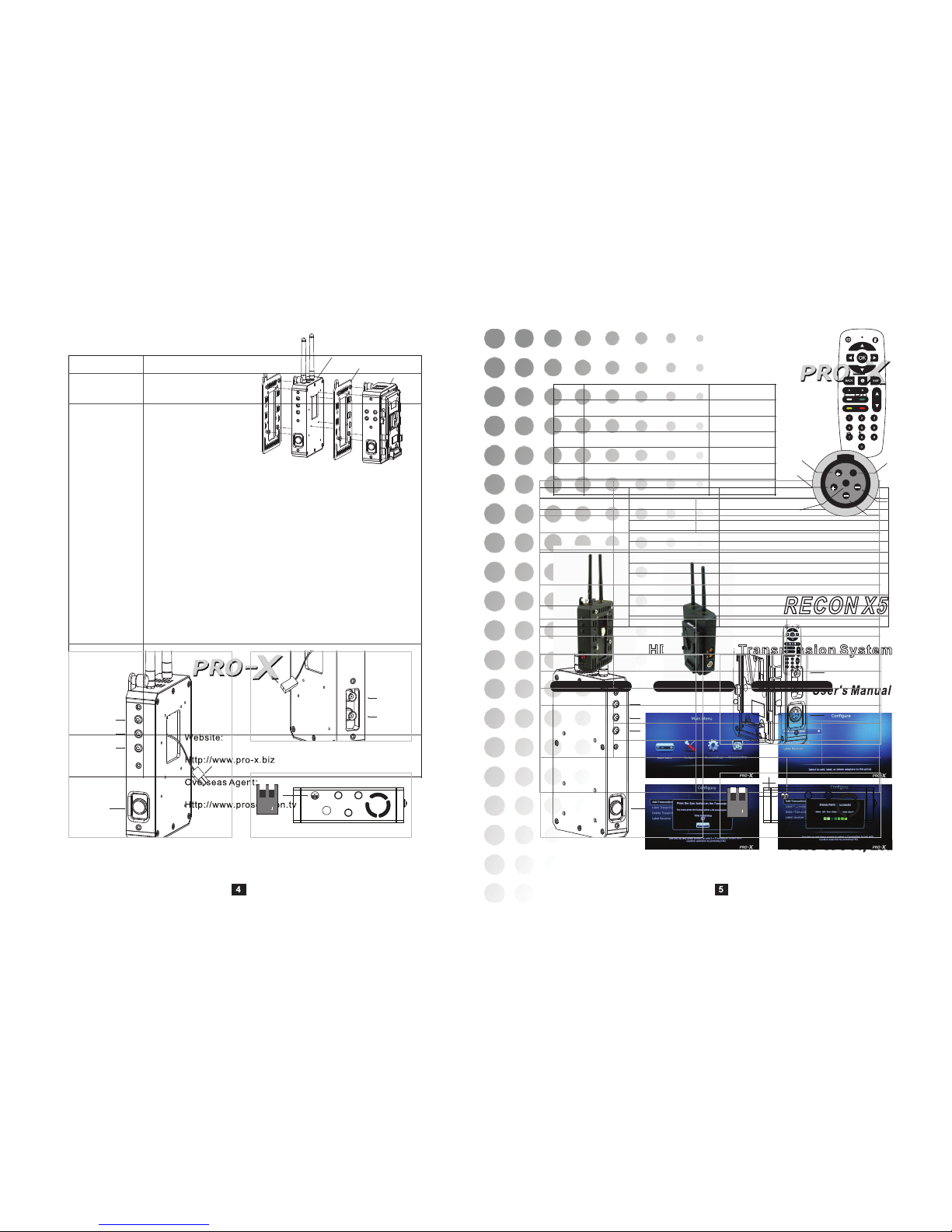
System Settings
Recon X5 can set up the system menu on the monitor by
the supplied remote control.(for all menu items see the
table below )
1.To power on RECON X5TX and RECON X5RX;
2.Connect the Recon X5RX with the monitor through the
BNC cable, and turn on the power switch on the monitor;
3.Press the Menu button on the remote control, the main
menu interface will appear on the monitor screen;
4.Press the left and right arrow keys to select the
corresponding options;
5.Press the OK button to enter the sub menu, press
BACK button to return to the previous menu.
Remote Control
Add a transmitter:(for example)
1. Select Configure in the Main Menu interface;
2. Select Add Transmitter in the Configure interface;
3. Select the transmitter you want to add, then press the Sync Button on
the transmitter (see RECON X5TX);
4. Added successfully.
Main Interface
Select Source
Configure
General settings
Advanced Settings
Sub Menu
Recon X5
Add Transmitter
Label Transmitter
Delete Transmitter
Label Receiver
Language
Latency Mode
Wireless Channel
Audio Mode
System Information
Reset to Factory
Remark
Select the different signal source
Add more transmitters
label the transmitter
Delete the transmitter
Label the receiver
Select the language
Game Mode is default Latency Mode
Select the appropriate WIFI channel
based on the environment
LPCM is default Audio Mode
Display the system information
Restore the factory settings
Important Information
Read this user’s manual carefully before use. It contains important
information and notes regarding operating.
The RECON X5 may not apply to the below cases:
。Repairs or product modification and alterations have been executed
by unauthorized service personnel.
。Damages is caused by accidents including but not limited to lighting,
water, fire, or moisture.
。Do not use power with specific power rating not compliant in the
specification.
。The serial number on the product has been altered, deleted, removed
or made illegible.
Danger: Be careful with electricity.
。Power to the units must be switched off before any work is undertaken.
。When the unit is not used for a long period, disconnect them from the
power source.
Warning
。Do not open the product.
。Indoor use only.
。Do not block the ventilation slots on the product.
。Put the product away from direct sunlight or any source of heat.
。Do not spill liquid on the product, especially with corrosive liquids.
。To reduce the risk of fire or electric shock, do not expose the RECON
X5TX and RECON X5RX to rain or moisture.
Special Notice
。Never use this product nearby an aircraft or high-accuracy electronic
instrument, It will cause an interference and wrong effect on the
operation.
。Never use this product in the following location where wireless wave
will cause the abnormal video and audio (noise, blocked image...etc,).
1. Installed in the walls with hard accessible material.
2. This device should be situated away from the refrigerator or metal
fitment.
3. Crowded place.
。This product has been tested and manufactured to comply with each
country’s safety rules. However, there is no guarantee that interference
will not occur in a few particular installation. If the interference is
happened, increase the separation distance between RECON X5TX
and RECON X5RX.
。RECON X5 is susceptible to interference from 5GHz wireless device,
such as router or other wireless device.
。Do not put RECON X5TX and RECON X5RX in a metal rack, which
may hinder the wireless communication.
。When wireless transmission is beginning, the product takes about
15-20 seconds to start the system, the media receiver can not be
operated during this time.
。Do Install the external antennas before use.
1 2
3 4
Introduction
This solution delivers uncompressed 1080i True Cinema video content
to your monitor.
It operates the transmission in
5.15GHz-5.25GHz, 5.725GHz-5.85GHz(non-
DFS Frequency Bands)
frequencies that can adjust its frequency automatically in case of interference with another RF system.
With external antennas, it can transmit uncompressed video content
with no latency.
Specification
Model
Video Formats
Audio Format
Antenna
Frequency
Applicable
Regulations
Interface
Audio/Video
Power Supply
Power Switch on Operation Panel
LED Light
Dimensions(mm)
RECON X5
SDI Input 1080p,1080i, 720p, 576i, 480i
Digital Audio Up to 3.072Mbps AC-3 and DTS
Omni – directional, high efficiency antenna system
5.15GHz-5.25GHz, 5.725GHz-5.85GHz(non-DFS
Frequency Bands)
FCC, CE, NCC, CCC
RECON X5TX RECON X5RX
SDI Input 1 No
SDI Output 1 2
Input Battery or JetPack 11V-17V DC
1RED
POWER LED 1
VIDEO LED 1
LINK LED 1
175(W)×105(L)×3 180(W)×100(L)×32
(H) (H)
Installation
Step1: RECON X5TX the transmitter:
1. Install the 2 external antennas.
2. Connect the BNC cable to the
High-Definition device's SDI OUT
socket.
3. Connect the BNC cable to
RECON X5TX's SDI IN socket.
4. Connect the JetPack or other
power supply equipment.
Step2: RECON X5RX the receiver:
1. Install the 2 external antennas
2. Adjust the DIP switch according to the input signal formats( See
RECON X5RX)
3. Connect the BNC cable to RECON X5RX's SDI OUT socket
4. Connect the BNC cable to the display device's SDI IN socket.
5. Connect the AC power supply.
Step3: Power on
Press the power switches to power on your RECON X5TX and RECON
X5RX, POWER LED indicators turn solid green.
If RECON X5TX receives SDI signals, VIDEO LED on the RECON X5
TX lights up; if the signal link between RECON X5TX and RECON X5
RX is established, LINK LED on the RECON X5RX lights up. In this case
the communication is normal, you can normally transmit signals.
JetPack
Connecting Plate
RECON X5TX
Connect the JetPack to RECON X5TX
SDI IN
SDI OUT
Power
output
VIDEO
Indicator LED
LINK
Indicator LED
Power
input
+
+
1
2
3
4
5
6
SDI OUT
SDI OUT
1 2
ON
Power Input
IR
1 2
ON
OVERVIEW
RECON X5TX
Operation Panel
。Power Switch with LED indicator
Press to turn RECON X5TX on or off. The above LED indicator turns
green when the power is on.
。LED Lights
VIDEO LED lights up when RECON X5TX receives and transmits signal.
LINK LED lights up when the signal link between RECON X5TX and
RECON X5RX is established.
Back Panel
1. SDI IN
For SDI signal input
2. SDI OUT
SDI signal loop out
Power Interface
1. Power Input Interface
Connect to JetPack or other power supply, input voltage: DC 11V-17V
(RED+, BLACK-)
2. Power Output Interface
Connect to the camera, output voltage: DC 11V-17V(RED+, BLACK-)
Sync Button
When users need to add the transmitter, press this sync button to couple
with the receiver. When adding, press lever 1 to ON, two seconds later,
reset it to OFF.
Power
Switch
Power
Indicator LED
Operation Panel
Back Panel
Bottom Panel
Operation Panel
Bottom Panel
Back Panel
RECON X5RX
Operation Panel
Power Switch with LED indicator
Press to turn RECON X5RX on or off. The above LED indicator turns
red when the power is on.
LED Lights
VIDEO LED lights up when RECON X5RX receives and transmits signal.
LINK LED lights up when the signal link between RECON X5TX and
RECON X5RX is established.
Terminal Connection Panel
1. 2 SDI OUT
SDI signal loop out
2. Power Input Interface (Type: EGG.2B.306)
Connect to external power supply equipment,
input voltage: DC 11V-17V
Pins: 1,2: +; 3,4: -; 5: Contact Judgment, need
to connect the negative: 6: Empty
DIP switch of signal format
When signal input is 1080p50, 1080p25,1080i50, 720p50, turn lever 1
upward to OFF;
When signal input is other formats, turn lever 1 downward to ON.
IR remote control signal receiving window
The remote control setup the system through this window.
Note: The remote control must face to this window when the system is
setting up.
VIDEO Indicator
LED
LINK Indicator
LED
Power Indicator
LED
Power
Switch
Power input
 Loading...