

SWIT Electronics FM-24DCI User Manual
Model: FM-24DCI
24" DCI-P3 Gamut Post Production Monitor
User Manual
Ver: A
SWIT Electronics Co., Ltd.
Please read this User M anual
throughout before using.

Preface
1. All internal technologies of this product are protected, including device, software and
trademark. Reproduction i n whole or in part without w r itten permission is prohibited.
2. All brands and trademarks of SWIT Electronics Co., Ltd. are protected and other relative
trademarks in this user m anual are the property of their res pect ive owners.
3. Due to constant effort of product development, SWIT reserves the right to make changes
and improvements to the product described in this ma nual without prior notice.
4. The warranty period of this pr oduct is 2 years, and does not cover the following:
⑴ Physical damage to the surface of the products, including scratches, cracks or other
damage to the LCD screen or other externally exposed parts;
⑵ The LCD dot defects are not over three;
⑶ Any damage caused by using third-party power adaptors;
⑷ Any damage or breakdown caused by use, maintenance or storage not according to the
user manual;
⑸ The product is disa ssembled by anyone other than an aut horized service center;
⑹ Any damage or breakdown not caused by the product design, workmanship, or
manufacturing quality, et c ;
*Any sales personnel ha ve no rights to provide ad ditional warranty.
5. For any suggestions and requirements on this product, please contact us through phone,
fax, Email, etc.
SWIT Electronics Co., Ltd.
Address: 10 Hengtong Road, Nanjing Economic and Technological Development Zone,
Nanjing 210038, P.R. China
Phone: +86-25-85805753
Fax: +86-25-85805296
Email: contact@swit.cc
Website: http://www.swit.cc
Maintenance
Warning
1. In order to reduce the risk of fire and electrical shock, do not lay this product in rain or
damp places.
2. Please keep away from the strong magnetic field; it may cause the noise of the video
and audio signals.
The power
1. Please use the power adapter prov ided or reco mmended by the manufa cturer in order to
avoid damage.
2. For a third party power adapter, please make sure the voltage range, supplied power,
and polarity of power lead ar e fit.
3. Please disconnect the power cable under the following situat ions:
(A). If you do not operate this monitor f or a per iod of time;
(B). If the power cable or power adaptor is damaged;
(C). If the monitor housing is broken.
The monitor
1. Please don't touch the screen with your fingers, which would probably deface the
screen.
2. Please don't press the screen; t he LCD is extremely exquisite and flimsy.
3. Please don't lay this product on unstable place.
Cleaning
1. Please clean the screen with dr y and downy cloth or special LCD c lea nser.
2. Please do not press hard when cl eaning the screen.
3. Please do not use water or other chemical cleanser to clean the screen. The chemical
may damage the LCD.
.

Contents
Preface .................................................................................................................................................... 2
Maintenace .............................................................................................................................................. 3
Contents .................................................................................................................................................. 4
1.Packing List .......................................................................................................................................... 4
2.Installation Dimensions ........................................................................................................................ 5
3.Installation instruc t io ns of accessories. ............................................................................................... 6
4.Operation Instructions .......................................................................................................................... 9
5.Menu Operations................................................................................................................................ 15
6.Specification ....................................................................................................................................... 51
1.Packing List
Stan dard Pac kage:
Optional accessries
1. Battery plate (V-mount)
2. Desktop Stand Feet
3. Sun hood
4. Protective Glass
5. Power cable
1. Hanger
Features:
24-inch, 1920x1200, 10-bi t LCD, 12-bit process, 100% DCI-P3
3G/HD/SD-SDI, HDMI monitoring
Built-in multi camera s De-log LUTs and DIT LUTs upload by USB
SDI 1/2 Pic-in-pic and Pic-by-Pic display
Waveform / Vector / Histogram / 16-ch Audio meters / Timecode
Peaking / Focus assist / Exposure assist / Zebra / Blue only
Anamorphic de-squeeze / Multiple markers
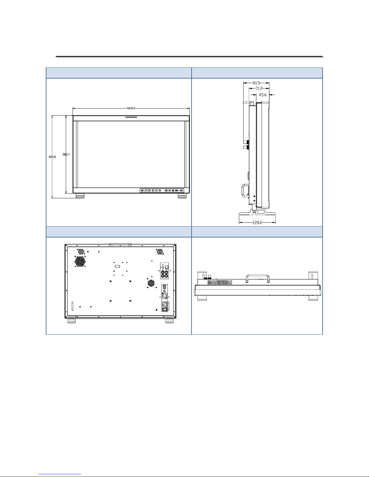
2.Installat ion D ime ns ion
Front Panel
Side View
Rear Panel
Top View
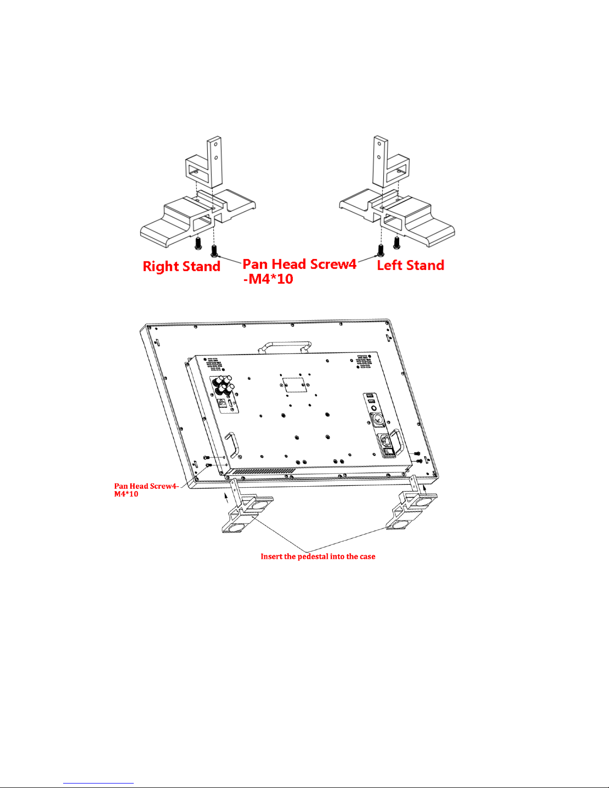
3.Installation instructions of accessories
Desktop Stand Feet

Sun hood
Protective Glass
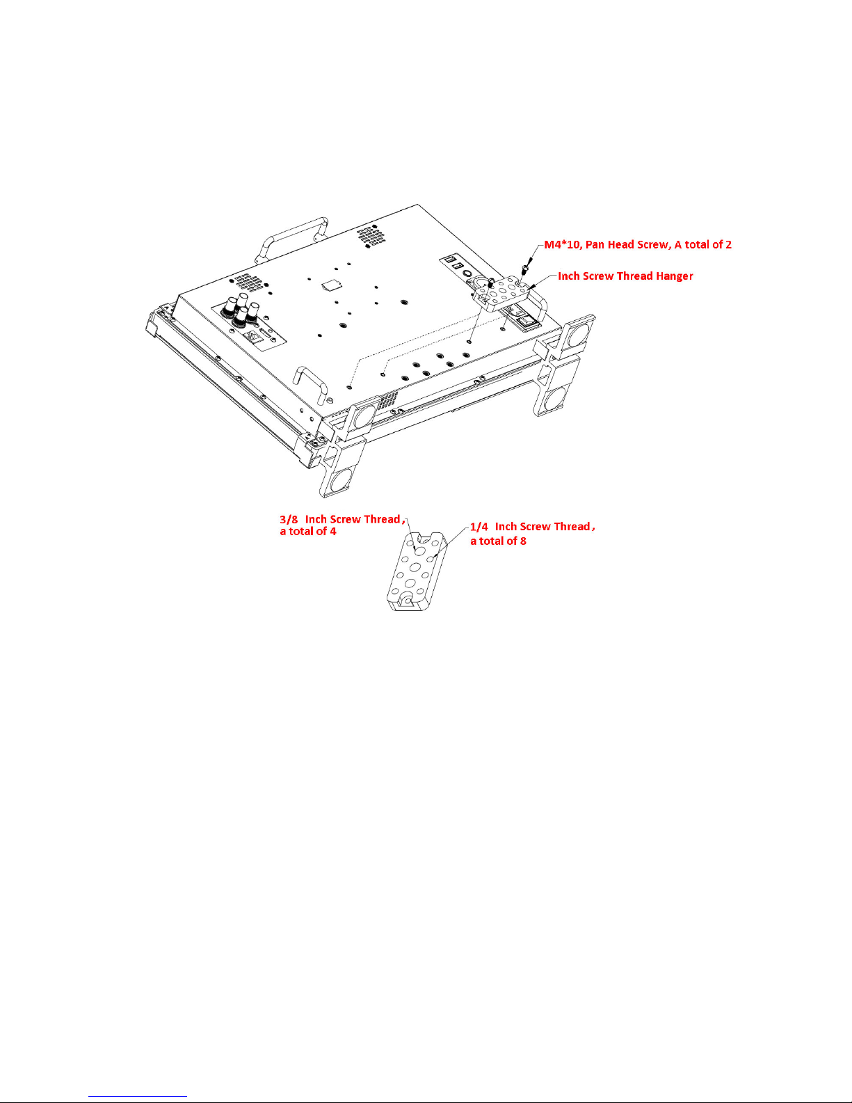
Hanger
It provides an inch screw thread hanger as an optional accessory. The hanger provides two
sorts of screw thread: 3/8 inch screw thread, a total of 4; 1/4 inch screw thread, a total of 8.
4.Operation Instructions
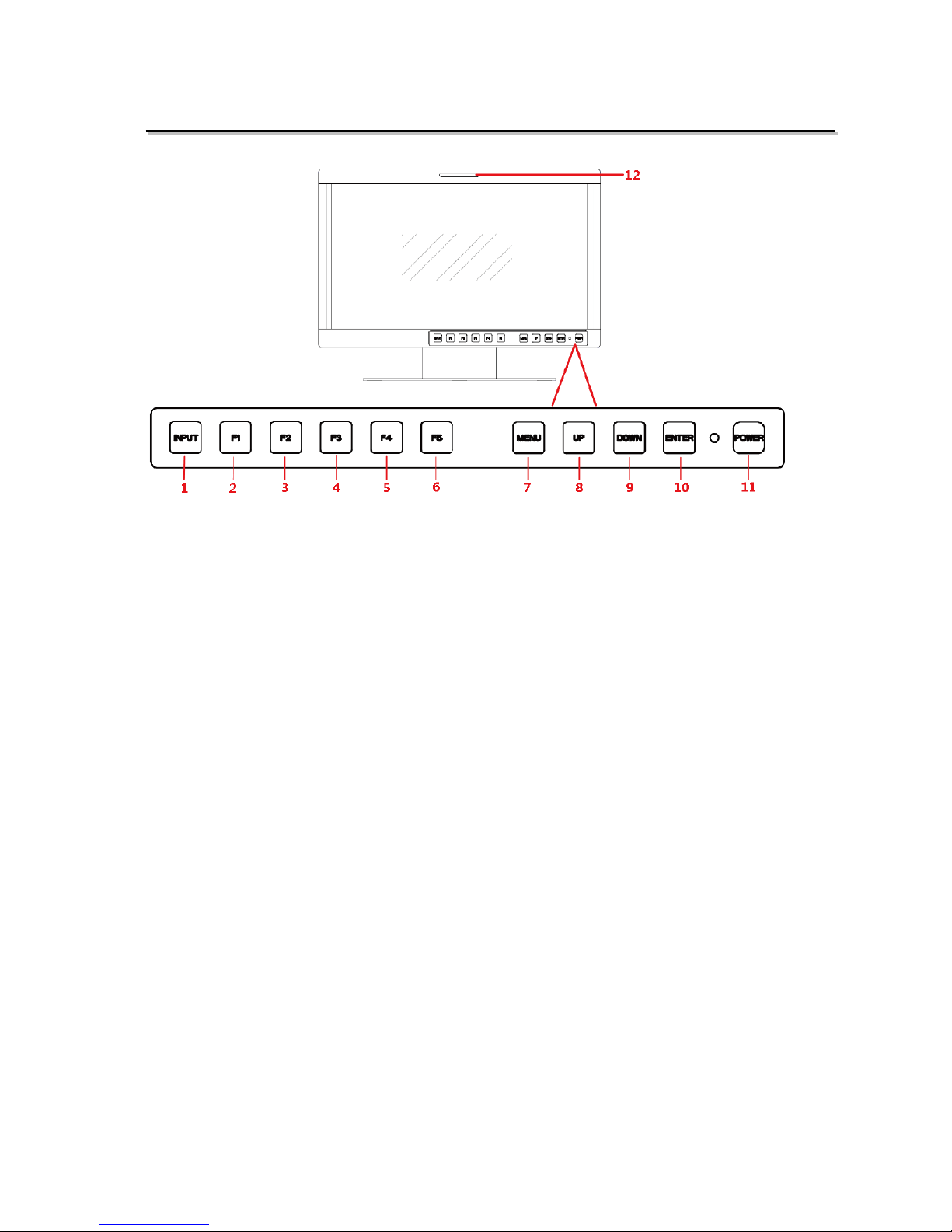
·Front Panel
1. INPUT: Input selection button
2. F1: Function button
3. F2: Function button
4. F3: Function button
5. F4: Function button
6. F5: Function button
7. MENU: Menu operation button
8. UP: Menu operation button
9. DOWN: Menu operation button
10. ENTER: Menu operation but t on
11. POWER/Lamp
12. TALLY: TALLY indicator(LED TALLY)
Function of Control Buttons
INPUT Selection Button
Press INPUT button and toggle or use the UP/DOWN button to select and display the
corresponding signal input to each connector.
SDI1
: monitor the
SDI
input as the active signal through the
SDI1 IN
connector.
SDI2
: monitor the
SDI
input as the active signal through the
SDI2 IN
connector.
LINE1(CVBS)
: monitor the
Composite Analog Input
as the active signal
through the
LINE1 IN
connector.
LINE2(CVBS)
: monitor the
Composite Analog Input
as the active signal
through the
LINE2 IN
connector.

LINE2(Y/C)
: monitor the
Composite Analog Input
as the active signal
through the
Y IN
connector and C IN connector.
LINE2(YPBPR)
: monitor the
Composite Analog Input
as the active signal
through the Y IN connector,
Pb IN
connector and
Pr IN
connector.
HDMI
: monitor the
HDMI
or
DVI
input as the active signal through the
HDMI
IN
connector.
When switching an input source, it will display the SOURCE menu at the right top corner of the
screen, and the current active source is labeled in highlight y ellow, as s how n i n Figure 4.1-2.
SDI1
LINE1(CVBS)
LINE2(CVBS)
LINE2(Y/C)
SOURCE
SDI2
LINE2(YPBPR)
HDMI
Figure 4.1-1 Source Menu
Particularly, in PIP/PBP display mode, the signal source for t he main picture is set by I NPUT
button, while the slave pict ur e’s is set through the CO NFIGSUB IN SELECT item in main
menu, refer to “4.1.7 CONFIG Menu” for the details.
Function Buttons
F1~F5 button are all function buttons. Pressing any F button will display the assigned Functions.
Pressing the desired function will select the funct ion. When selected, the Function will then toggl e
through the desired setting inc luding OFF.
The function of each button can be set via the FUNCTION KEY setting in the main menu.
OPERATION: for example
, press F1 to display the
FUNCTION
menu at the left bottom
corner of the screen, as show n in Figure 4.1-3. Toggle F1 button to change the value related
to this function without the set t ing value display.
F1 ONFLASE COLOR
F2 OFFNATIVE
FUNCTION
F3 OFFMONO
F4 OFFFREEZE
F5 OFFPBP

Figure 4.1-2 Function Menu
The
FUNCTION
menu will be closed autom at ically ten seconds after t he last button push.
You can assign var ious functions to each F1~F5 button through
FUNCTION KEY
menu.
Refer to "4.1.9 FUNCTION KEY Menu" for the details.
FACTORY RESET Function.
Press and hold the INPUT+F2 button for 3 seconds to access the menu in Figure 4.1-4.
Factory Reset Now?
No
Yes
FACTORY RESET
Figure 4.1-3 Reset Menu
Menu Operation Buttons
Display or set the MAIN menu.
MENU Button
Used to activate MAIN me nu.
Press to display the MAIN menu
Press again to clear the MAIN menu
UP
Used to navigate on-screen menu.
Toggle this button to select the previous item or increase the item value.
DOWN
Used to navigate on-screen menu.
Toggle this button to select the next item or decrease t he it em value.
ENTER
Used to navigate on-screen menu, confirm selection with the MAIN menu, or load t he Adjust
menu.
MENU Selection and Setting
When displaying the MAIN menu, pres s
ENTER
button to select a menu ite m or set ting value,
the active item is labele d in a h ighl ight c olor, then press
ENTER
button to con fir m the set ting s,
otherwise, press
MENU
button to give up the modif i cat ion and turn back the higher lev el
menu item.
Refer to “4.2 Menu Settings” for det ai l about the MAIN Menu operatio ns.
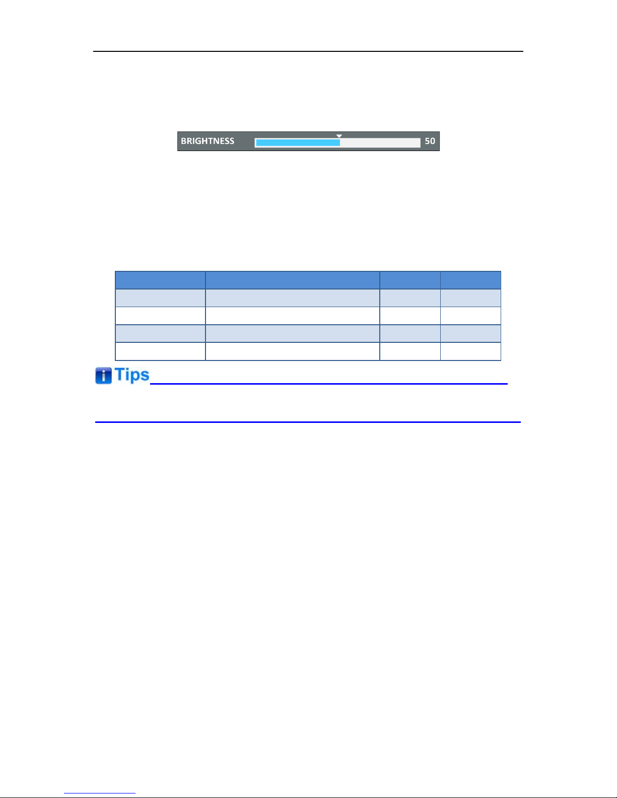
Adjust Menu-Adjust VOLUME, BRIGHTNESS, CONTRAST, CHROMA
When not displaying the MAI N menu, press
ENTER
button to display the
Adjust
menu, as
shown in Figure 4.1-5.
Toggle among these adjustable items: VOLUME, BRIGHTNESS, CONTRAST, CHROMA.
Figure 4.1-4 Adjust Menu
After displaying the Adjust menu, press UP or
DOWN
button to adjust the item value, and
then press
ENTER
button to confirm the value setting. The relat ionship of the items and their
range is list in Table 4.1-1:
Table 4.1-1 The Description of Adjust Menu Items
Adjust Menu
Description
Range
Default
VOLUME
Adjust the volume
0~31dB
16
BRIGHTNESS
Adjust the image brightness
0~100
50
CONTRAST
Adjust the image contrast
0~100
50
CHROMA
Adjust the image monochroma
0~100
50
The
Adjust
menu will be closed automatic al ly ten seconds after the la st but t on pus h.
Power Button and Indicator
Used to turn the power to place the monitor into standby mode/off.
When the device is off(Re d), press t he
POWER
button to tur n it on. The power indicator light s
in green.
Flashing green indicates no s ign al is present (refer to section 3. 1.1)
When the device is on, press t he
POWER
button to turn it off. The power indicator lights in
red.
Arrangement of Rear Panel
For the arrangement of the r ear panel of FM-17 is shown in Figure 4.2-1, there are various
input and output interfaces at t he r ear panel, and build-in speakers in the top.
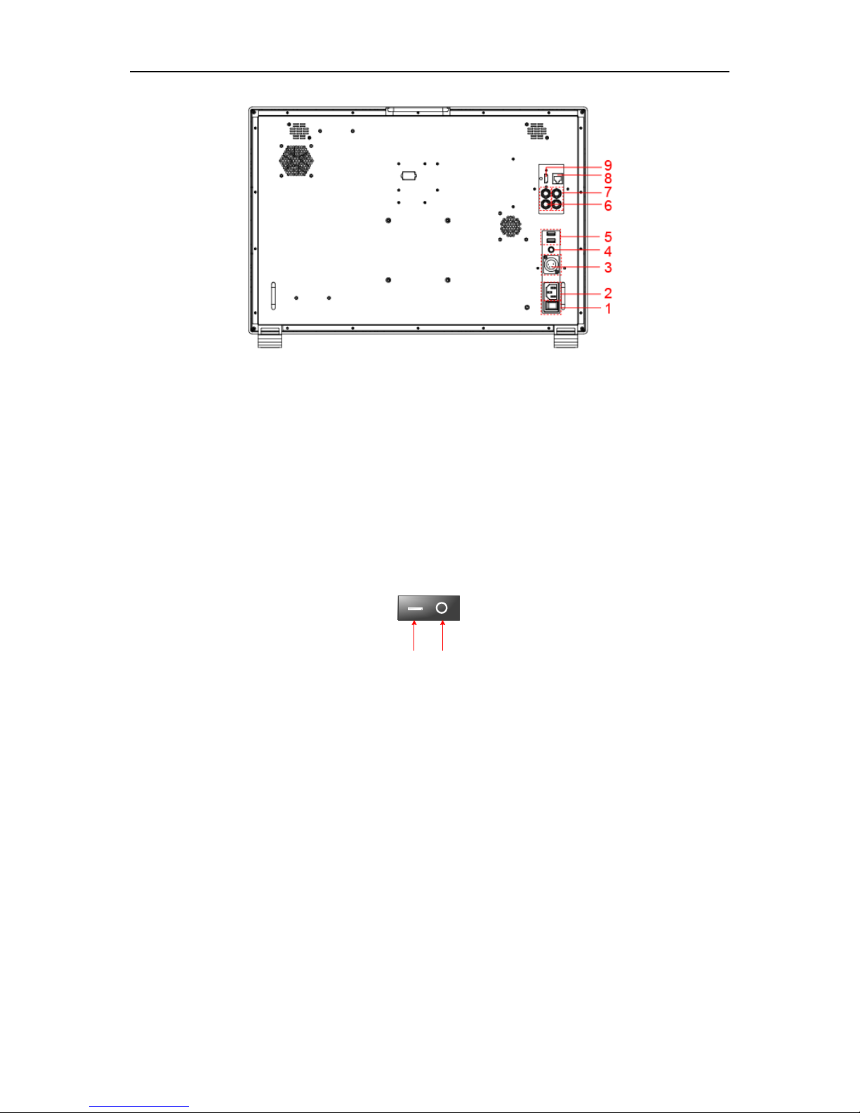
Figure 4.2-5 The Rear Panel of FM-24DCI Monitor
13. Power Switch
Press this part to switch on or switch off the power.
Push the button to the “-” icon to sw itch on the power.
Push the button to the “” icon to sw itc h off the power.
ON OFF
Figure 4.2-6 Power Switch
14. Power Input-AC IN
Plug the power supply to this inter f ac e t o pr ovide power to the device.
The specification is 100~240V 50/60Hz AC.
15. Power Input- DC IN 14.5V
One DC input interface from batter y powered, 14.5V DC.
16. Power Output-DC OUT 12V/ BATT 1.5A
One DC output interface, 1. 5A DC. This interface provides a LEMO two core socket of 1.5A
current limichut. When using AC power supply, t he output voltage is 12V, and when using
battery powered, the outp ut voltage is consistent with the output voltage of b at t er y.
17. Power Output-DC OUT 5V 1AX2
Two D C output interfaces, 5V1A DC.
The
two DC OUT interfaces
only provide power supply of 1A curr ent l imit, without data
communication service.
Particularly for LCM215-E, the DC outputs including the LEMO out put (DC OUT 12V/BATT
1.5A) and the two USB outputs(DC OUT 5V 1A) ar e only available when usin g t he DC
input(DC IN 14.5V) as the unit pow er supply interface!
18. SDI1 IN, SDI2 IN(BNC)
Two S DI sign al input interfaces, support m ultiple format HD/3G-SDI inputs.
19. SDI1 OUT, SDI2 OUT(BNC)
Two S DI sign al output interfaces.
20. HDMI IN(HDMI)
One HDMI signal input inter fac e, HDMI Type-A connector, support HDMI or DVI signal.
21. Ethernet(RJ-45)
A 10/100M Ethernet interface. Provide connect ion to a computer for external cont r ol.
Only use the adapter and the pow er cor d specified by the manufacture for your safety!
5.Menu Operations
This chapter describes the structur e and functio nality of t he On-Scr een Men u, and intro duces how
to modify and customize the m enu settings.
The Main Menu consists of the following sections: STATUS, INPUT SELECT, MARKER, AUDIO,
DISPLAY, CLOSED CAPTION , CONFIG, LOOK PROFILE, FUNCTION KEY and KEY INHIBIT,
as shown in Figure5-1.
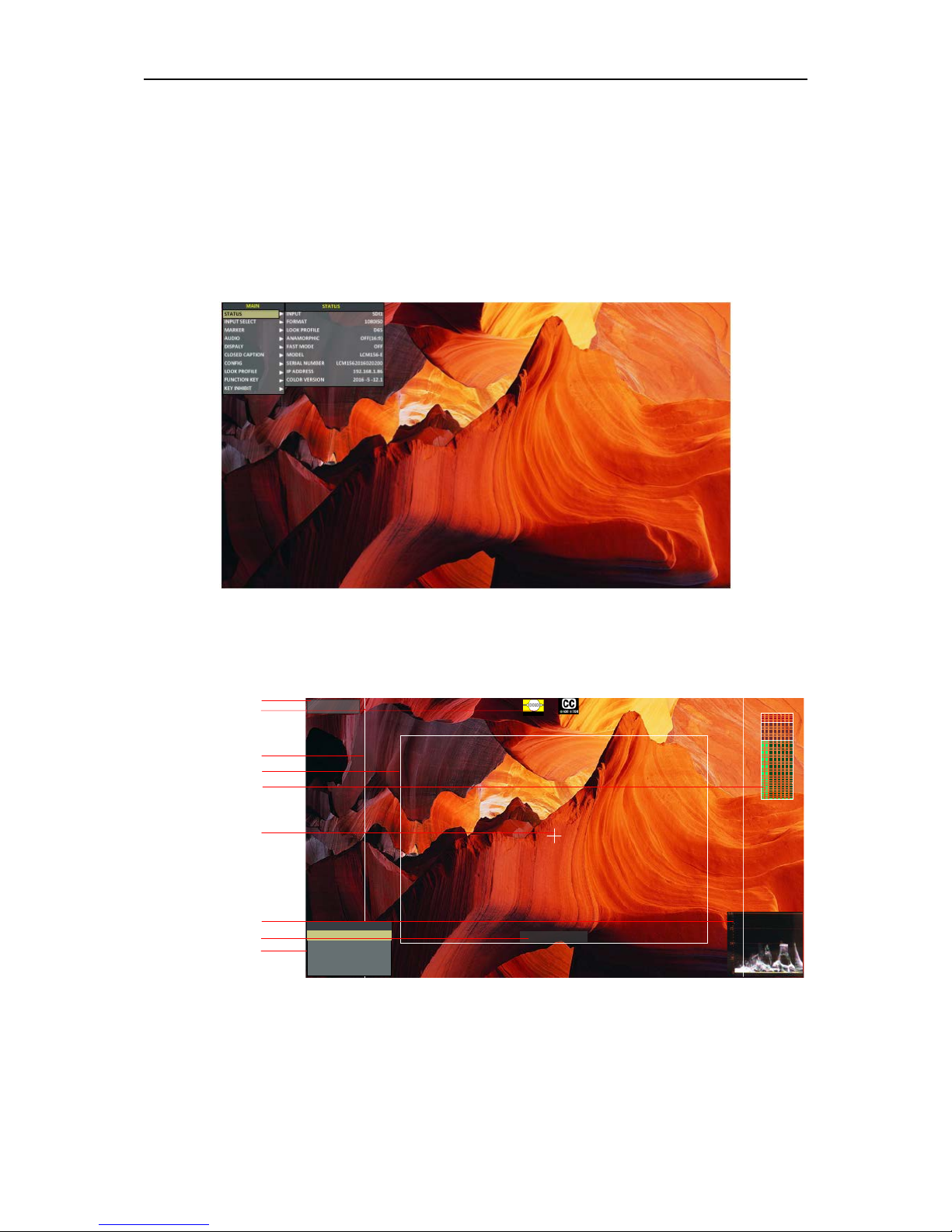
Figure 5-1 On-Screen Menu
The features on the screen ar e as shown in Figure 5-2:
SDI1
1080I59.94
--:--:--:--
1 2 3 4 5 6 7 8
Status Information
Audio Meter
Center Marker
Timecode
Safe Marker
Area Marker
Adjust Menu
Wave Form
AFD CC
F1 OFFFOCUS ASSIST
F2 OFFNATIVE
FUNCTION
F3 OFF(16:9)ANAMORPHIC
F4
OFF
FALSE COLOR
F5 OFF
PBP
Figure 5-2 Features of LCM156-E Monitor
Status Information: it displays the input channel and signal format. Set by DISPLAY Status
Display item.
AFD Information: Set by DISPLAY AFD Dis play item.
CC Information: Set by CLOSED CAPTION menu.
Marker Information: including Area Marker, Center Marker and Safety Maker, and set by Marker
menu.
Audio Meter: Set by Audio menu.
Wave Form: Set by DISPLAY menu.
Time Code: Set by DISPLAY menu.
FUNCTION Menu: it will pop up when pressing the F1~F5 button, and set by FUNCTION menu.
Please refer to the corres ponding sections for the details in this chapter.
Main Menu
Display the Main Menu
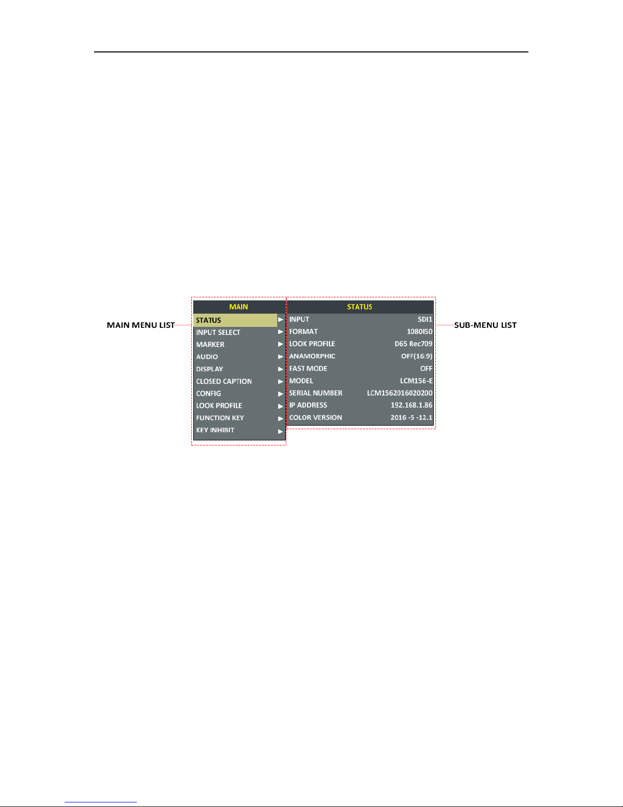
Press the MENU button to display the Main Menu at the top left corner of the screen, as s hown in
Figure 5.1-1:
Figure 5.1-1 the Structure of the Main Menu
The menu interface is divided i nt o t wo parts: Main Menu List and Sub-menu list.
Menu Control
You may control these various functions using MENU, UP, DOWN and ENTER buttons. Follow
the instructions below:
Press UP or DOWN to navigate to a menu item, then, press Enter button to enter into the
sub-menu list of the selected ite m.
1. Press
MENU
button to display the MAIN Menu.
2. Press UP or
DOWN
button to move the control ico n to y our t ar get menu item in mai n menu
list, here, the control icon is a highl ight yellow rectangle which i s us ed to label the current
active selection.
3. Press
Enter
button to access the sub-menu list of the selected main menu, and press UP
or
DOWN
button again to select y our target sub-menu item whi ch you want to modify its
value.
4. Press
Enter
button to confirm the selection of your target s ub-menu item, and press UP or
DOWN
button to adjust its value from its sub-me nu i t em list .
 Loading...