

SWIT Electronics FM-17, FM-21HDR User Manual
Model: FM-17
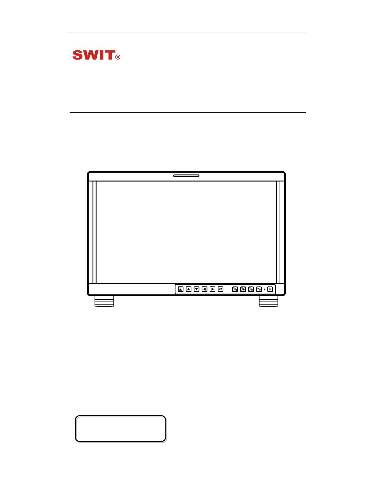
17.3" FHD Production Monitor
User Manual
Ver: A
SWIT Electronics Co., Ltd.
Please read this User M anual
throughout before using.

Preface
1. All internal technologies of this product ar e pr ot ect ed, includ ing device, software and
trademark. Reproduction i n whole or in part without w r itten permission is prohibited.
2. All brands and trademarks of SWIT Electronics Co., Ltd. are protected and other
relative trademarks in this us er manual are the property of t heir r espective owners.
3. Due to constant effort of product development, SWIT reserves the right to make
changes and improvements to the product described in this manual without prior
notice.
4. The warranty period of this pr oduct is 2 years, and does not cover the following:
⑴ Physical damage to the surface of the products, including scratches, cracks or
other damage to the LCD screen or other externally exposed parts;
⑵ The LCD dot defects are not over three;
⑶ Any damage caused by using third-party power adaptors;
⑷ Any damage or breakdown caused by use, maintenanc e or st or age not according
to the user manual;
⑸ The product is disass embled by anyone other than an authorized service center ;
⑹ Any damage or breakdown not caused by the product design, workmanship, or
manufacturing quality, et c ;
*Any sales personnel ha ve no rights to provide ad ditional warranty.
5. For any suggestions and requirements on this product, please contact us through
phone, fax, Email, etc.
SWIT Electronics Co., Ltd.
Address: 10 Hengtong Road, Nanjing Economic and Technological Development Zone,
Nanjing 210038, P.R. China
Phone: +86-25-85805753
Fax: +86-25-85805296
Email: contact@swit.cc
Website: http://www.swit.cc

Maintenance
Warning
1. In order to reduce the risk of fire and electrical shock, do not lay this product in
rain or damp places.
2. Please keep away from the strong magnetic field; it may cause the noise of the
video and audio signals.
The power
1. Please use the power adapter provided or recommended by the manufacturer in
order to avoid damage.
2. For a third party power adapter, please make sure the voltage range, supplied
power , and polarity of power lead are fit.
3. Please disconnect the power cable under the following situat ions:
(A). If you do not operate this monitor f or a per iod of time;
(B). If the power cable or power adaptor is damag ed;
(C). If the monitor housing is broken.
The monitor
1. Please don't touch the screen with your fingers, which would probably deface the
screen.
2. Please don't press the screen; t he LCD is extremely exquisite a nd flimsy.
3. Please don't lay this product on unstable place.
Cleaning
1. Please clean the screen with dr y and downy cloth or special LCD c lea nser.
2. Please do not press hard when cl eaning the screen.
3. Please do not use water or other chemical cleanser to clean the screen. The
chemical may damage the LCD.

Contents
Preface .....................................................................................................................................................2
Maintenace ..............................................................................................................................................3
Contents ...................................................................................................................................................4
1.Packing List ...........................................................................................................................................4
2.Installation Dimensions .........................................................................................................................5
3.Installation instruc t io ns of accessories .................................................................................................6
4.Operation Instructions .........................................................................................................................12
5.Functionality of the Main Menu. ..........................................................................................................19
6.Specification ........................................................................................................................................51
1.Packing List
Stan dard Pac kage:
Optional accessries
1. Battery plate (V-mount)
2. Desktop Stand Feet
3. Sun hood
4. Protective Glass
5. Power cable
1. C-Stand
2. Hanger
Features:
17.3-inch, 1920x1080, 8-bit LCD, 12-bit process
3G/HD/SD-SDI, HDMI, CVBS monitoring
Built-in multi camera s De-log LUTs and DIT LUTs upload by USB
Waveform / Vector / Histogram / 16-ch Audio meters / Timecode
Peaking / Focus assist / Exposure assist / Zebra / Bl ue only
Anamorphic de-squeeze / Multiple markers
Portable, light weight and C-stand setup

2. Installatio n D im e ns ion
Front Panel
Side View
Rear Panel
Top View
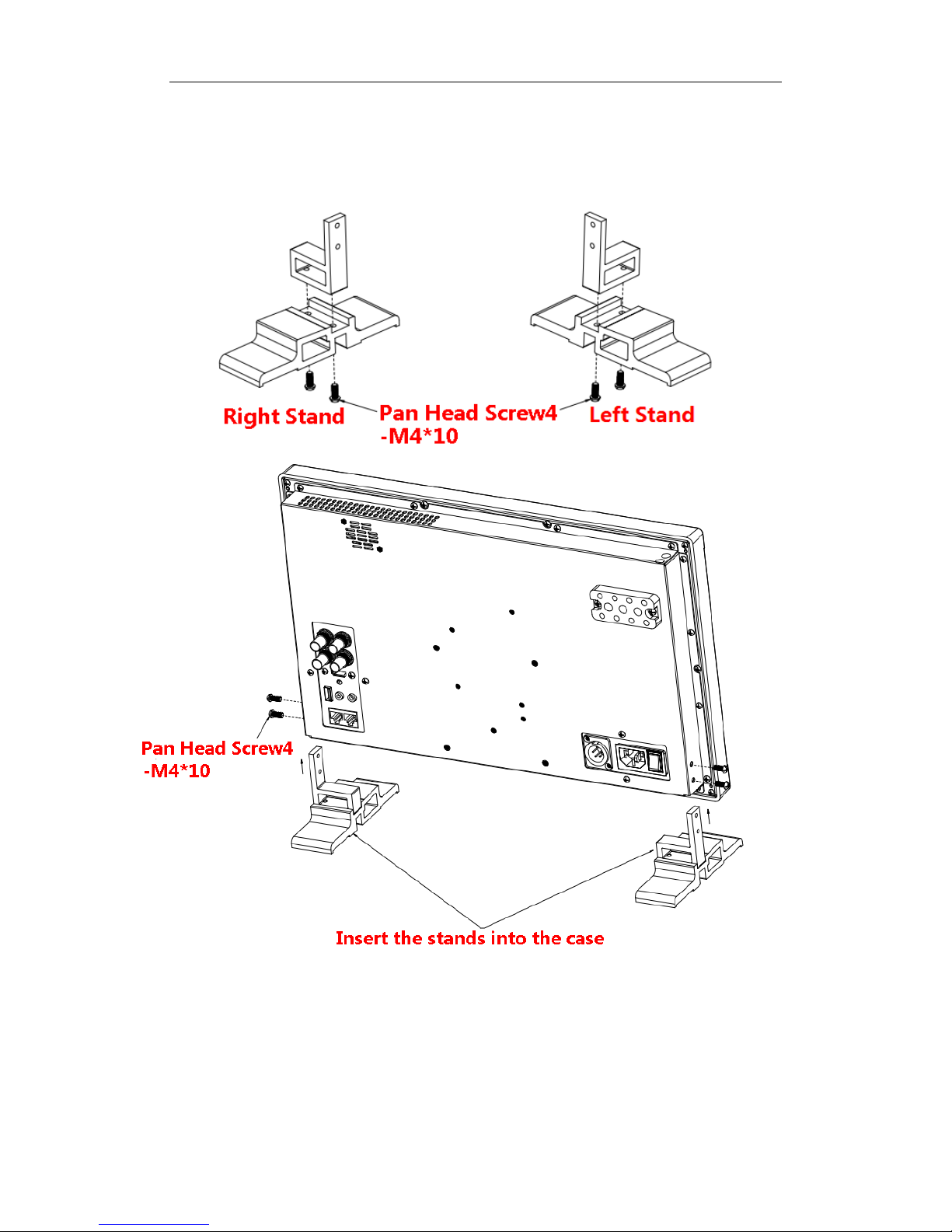
3. Installation instructions of accessories
Desktop Sta nd Feet
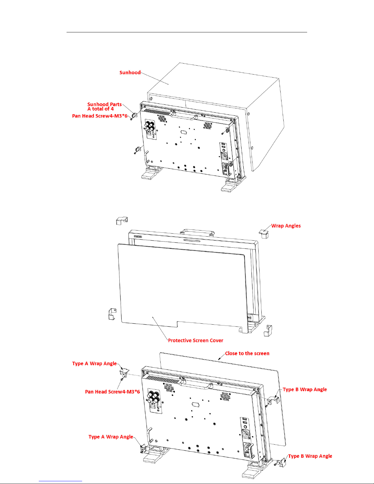
Sun hood
Protective Glass
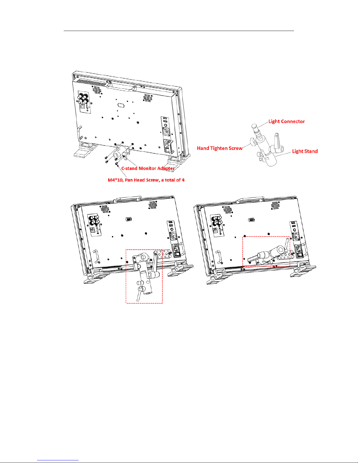
C-Stand
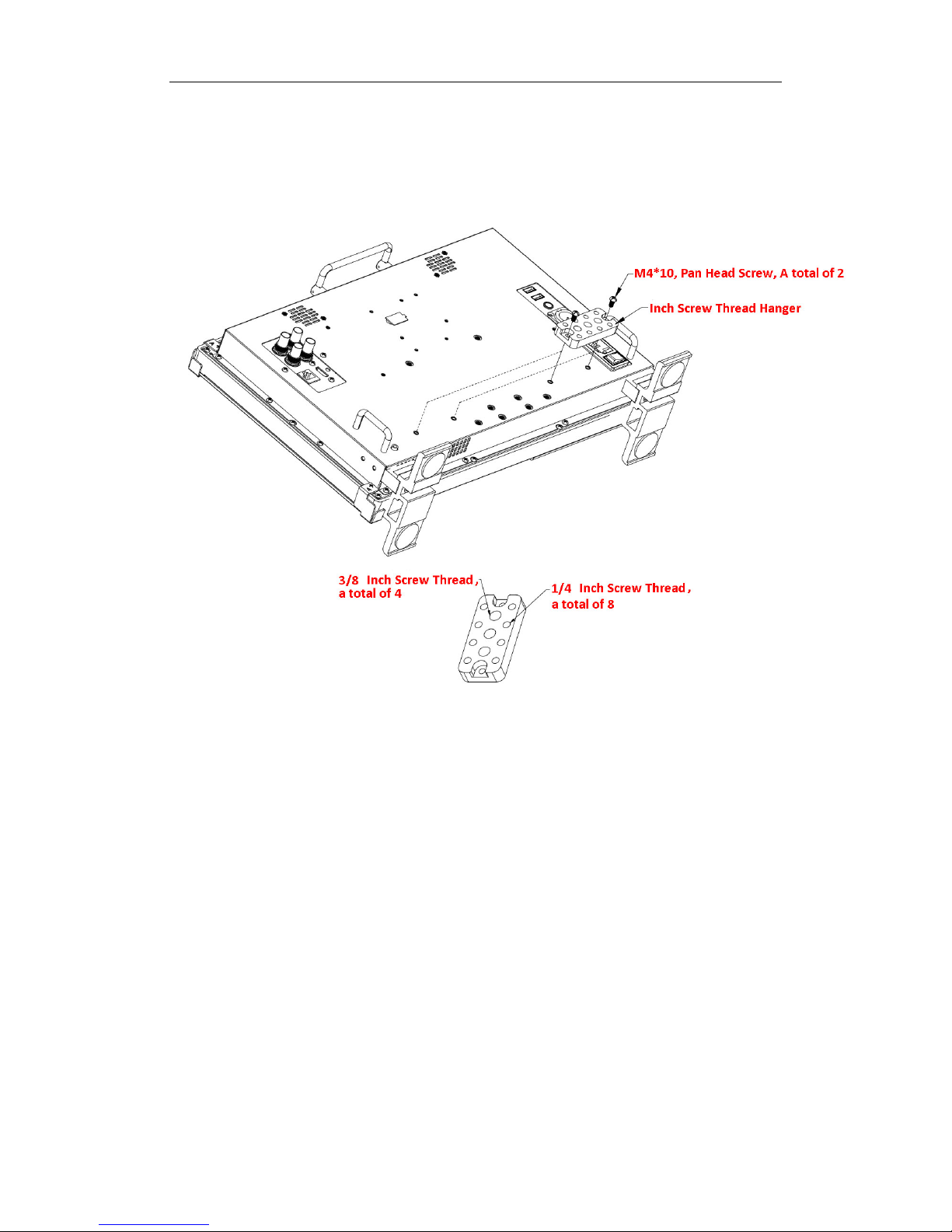
Hanger
It provides an inch screw thread hanger as an optional accessory. The hanger provides
two sorts of screw thread: 3/8 inch screw thread, a total of 4; 1/4 inch screw thread, a
total of 8.
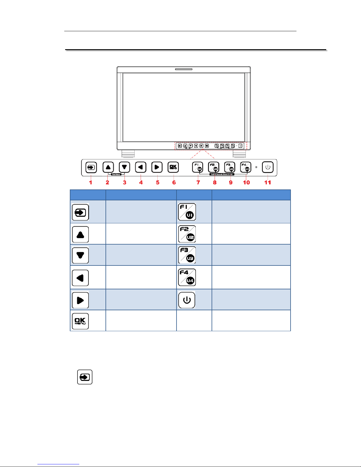
4. Operation Instructions
BUTTON
FUNCTION
BUTTON
FUNCTION
Input selection Function button F1
Adjust upward Function button F2
Adjust downward
Function button F3
Return/Exit Function button F4
Select next Power on/off
Save/Return/Main menu
All of these buttons have light ind icators.
4.1 Operation of Front Panel
The functionality and usage of the buttons at the front panel are as follows:
: Input Selection
Select the input signal from each input interface. Press this button to display the
input source menu at the top right corner of the screen, as shown in Figure 1. Use it
to select an input signal source, pr ess it again to toggle among these input signal
items, or after the input source menu displayed, use the UP or DOWN button to
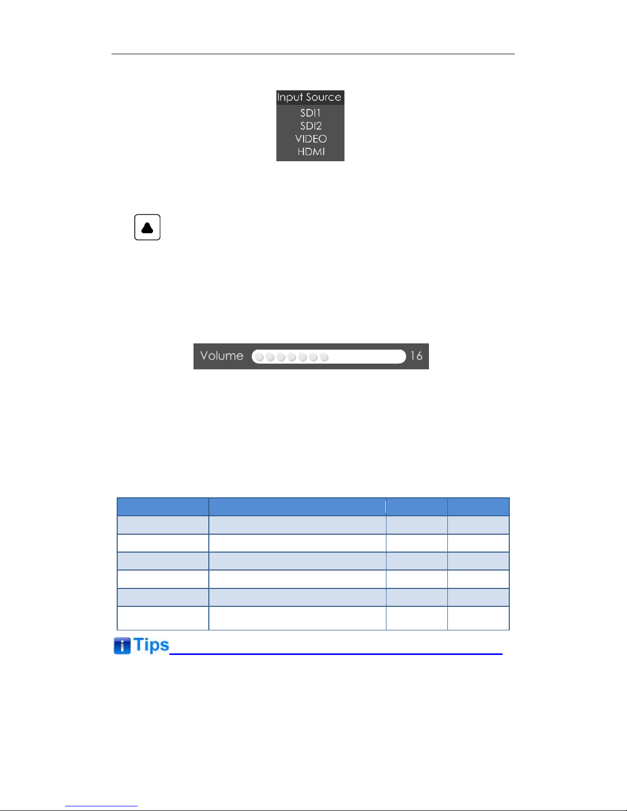
toggle among these input sign al items.
Figure 1 Source Menu
: UP ARROW
It is UP button when working with the main menu. Toggle this button to select
the next item or increase the nu mb er.
Without the Main menu: when not displaying the Main menu, press
LEFT
button to display the
Fast Menu
list, as shown in Figure 2, toggle among these
menu items:
Volume, Brightness, Contrast, Saturation, Backlight
and
Sharpness
.
Figure 2 Fast Menu List
After displaying the
Fast Menu
, press
LEFT
or
RIGHT
arrow button to adjust t he
menu value.
The limitations of these it ems are shown in Table 4.1-1:
Table 4.1-1 The Description of Fast Menu Items
Adjust Menu
Description
Range
Default
Volume
Adjust the volume
0~31
16
Brightness
Adjust the image brightness
0~100
50
Contrast
Adjust the image contrast
0~100
50
Saturation
Adjust the image color intensity
0~100
50
Backlight
Adjust the backlight
0~10
5
Sharpness Adjust the image sharpness
0~63
8
After you have loaded the adjust menu list, it will be clos ed aut omatically if you do
nothing operation on it within t he
Osd Time
.
The main menu, the fast menu, t he function menu and the i nput sign al selecti on list of
a screen may not be shown all s i mu ltaneously.

: DOWN ARROW
It is
DOWN
button when working with the main menu. Toggle this button to
select the next item or decr ease t he number.
Without the Main menu: when not displaying the Main menu, press
DOWN
button to display the
Fast Menu
list, refer to the details in the above description
as in UP arrow button.
: LEFT ARROW
Press this button to do the follow ing operations:
With the Main menu: when working with the Main menu, LEFT button achieve
the following functions:
Back to the higher level menu
B ack to the higher level menu and not save the setting of the menu item
value
Quit the Main menu
With the Fast menu: when displaying the Fast menu, press
LEFT
button to
decrease the item value.
: RIGHT ARROW
Press this button to do the follow ing operations:
With the Main menu:
Enter into the next level menu.
Turn Page: when the current selection in the sub-menu list is
Next Page
,
press this button to turn to the next page circularly.
With the Fast menu: when displaying the Fast menu, press RIGHT button to
increase the item value.
OK/MENU
It is used to activate the Main menu. Pr ess this button to do some operat ions with
the Main menu, it includes the fol lowing operations:
Display the Main menu: press
OK/MENU
button, it will display t he main menu at
the center of the screen.

Save/Back: confirm the selection and back to the higher level menu.
Turn Page: when the current selection in the sub-menu list is
Next Page
, press
this button to turn to the next page circularly.
F1/U1
This button is a
FUNCTION
and
User Preset
button.
F1 function:
The F1 function can be assigned via the CONFIG menu. Press
the function button to activate or deactivate the assigned function. Press F1 to
display the function menu list in the center of the screen, as shown in Figure
4.1-4. Toggle F1 button to change the value related to this function.
Figure 4.1-1 Function Menu List
USER1:
Switch to
User Preset USER1
directly. Hold 2 seconds to select the
current user preset to be User1. The name of the current user preset will be
prompted on the left center of the screen. Refer to “5.1.4.1 FUNCTION KEY
and User Preset Menu” for t he set ting of
User Preset.
If the value related to the function but t on c an’t be modified, the value shows in gray.
For
F2/U2~F4/U4
function buttons, t he oper at ions are as the same as F1/U1' s.
Use
FUNCTION KEY
menu to assign F1~F4. You can assign the function from
among: Camera LUT, Undef, Blue Only, Mono, Marker, Audio Meter, Time Code,
Wavefor m T ype, Vectorscope, Histogram, Scan, Aspect, Native, Mute, IMD Display,
False Color , Focus Assist, Peak, Zebra. Refer to "5.1.4 USER CONFIG Menu " for the
details.
Power
Used to power on or st andby, and the light in the button will ind icate th e st at us of the
power . When the monitor is powered on, t he lig ht is green, press the power but ton
and hold 2 seconds, it will enter int o standby mode, the light is red.
4.2 Rear Panel Features
It will introduce the arrangement and the operations of the interfaces in rear of the panel
in the following.
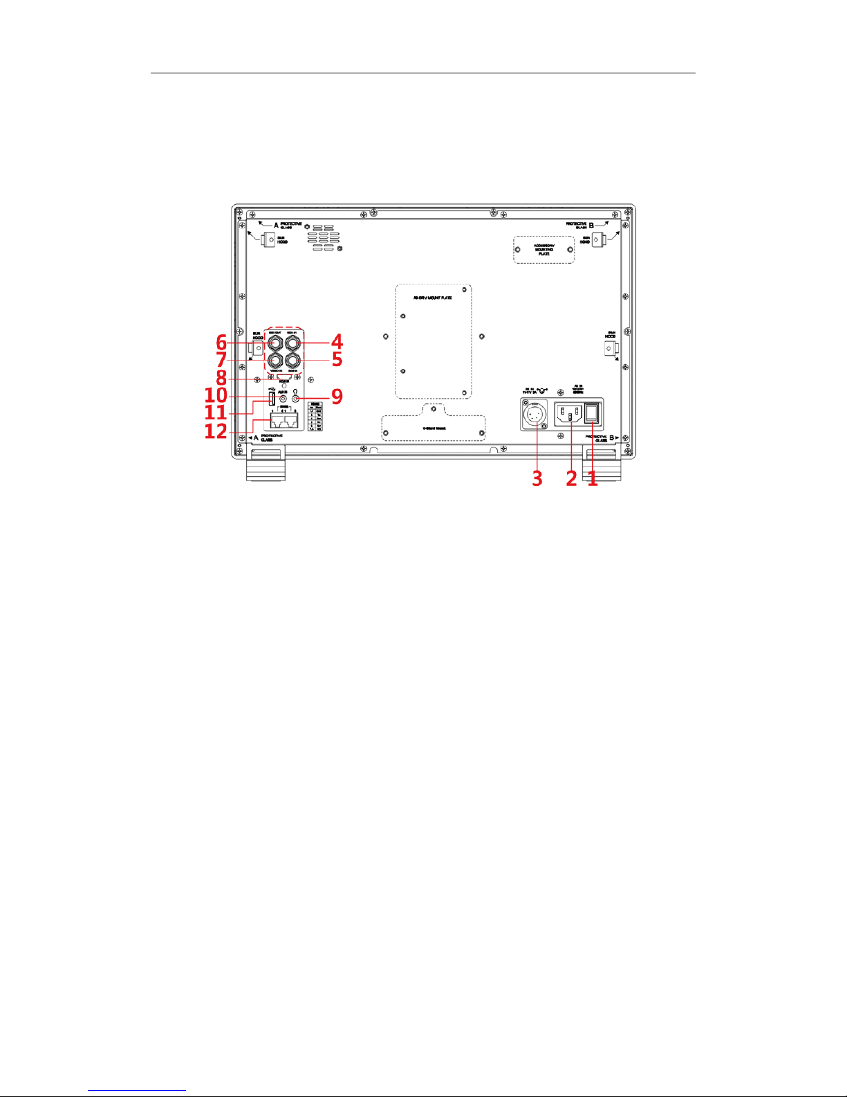
Arrangement of Rear Panel
For the arrangement of the r ear panel of FM-17 is shown in Figure 4.2-1, there are
various input and output inter fac es at the rear panel, and bui ld-in speakers in the
top.
Figure 4.2-2 The Rear Panel of FM-17 Monitor
The interfaces numbered in r ed ar e described as follows:
1. Power Switch
2. AC Power Input
3. DC Power Input
4. Video Input: SDI 1 I N
5. Video Input: SDI 2 I N
6. Video Output: SDI1 OUT
7. Video Input: VIDEO IN
8. HDMI Input: HDMI IN
9. Headphone
10. Audio Input: AUD IN
11. USB
12. RS485 X2
Operations of Rear Panel
The details of these interfaces at the rear pane l are described as follows:
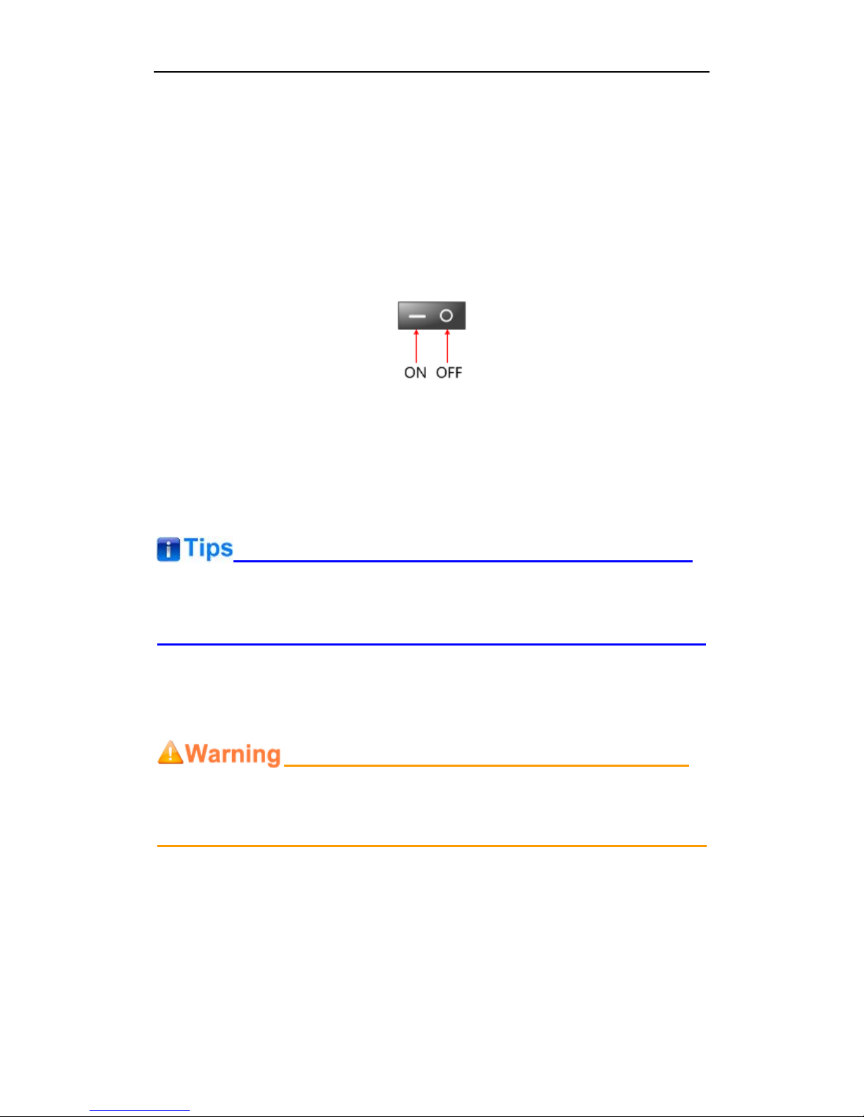
Power Switch
It provides one power switch to switch on or switch off. As shown in Figure 4.2-2,
push the button to the direction “-” to switch on the power, or push the button to the
direction “O” to switch off the power.
Figure 4.2-3 Power Switch
AC Power Input
It provides one AC power input interface, the specification is 100 ~
240V50/60HzAC.
The power indicator is on the pow er but t on at the front panel. If the light is green, the
monitor is powered on, and if the lig ht is r ed, t he monitor is standby.
DC Power Input
It provides one DC power input interf ac e, t he specification is 11~17V3A DC.
Only use the adapter and the pow er cor d specified by the manufacture for your
safety!
Video Input Interface ( B NC) SDI1 IN~SDI2 IN
It provides two SDI input inter faces, labeled as SDI1 IN, SDI2 IN.
Video Output Interfa ce ( BNC) SDI1 OUT
It provides one SDI output interface, labeled as SDI1 OUT.
Video Input(BNC): VIDEO IN

HDMI Input: HDMI IN
It provides one HDMI input inter face, HDMI Type-A connect or with a fastener.
Audio Output(3.5mm jack): it provides one headphone.
Audio Input(3.5mm jack): AUD IN, it provides one audio input interfa ce .
USB: it is used for LUT input and firmware upgrading.
RS485 Interface (RJ-45)
It provides two RS485 interfaces, loop out. Support for cascade connection and
IMD remote control. The comparison of pins and Input connectors for RS485 is
shown as in Table 4.2-1:
Table 4.2-2 The Comparison of Pins and Input connectors for RS485
PIN No.
RS485 IN Terminal Sign al
1,2
GND
3
Tx- 4 Rx+
5
Rx-
6
Tx+
7,8
NC
Supported Signal Format
The supported signal format for t his device is as shown in Table 4.3-1:
Table 4.3-1 Supported Signal Format
Signal SDI HDMI VIDEO
NTSC
PAL
SD
480I60
4:2:2 YCbCr 10 BIT
576I50
 Loading...