

Page 1
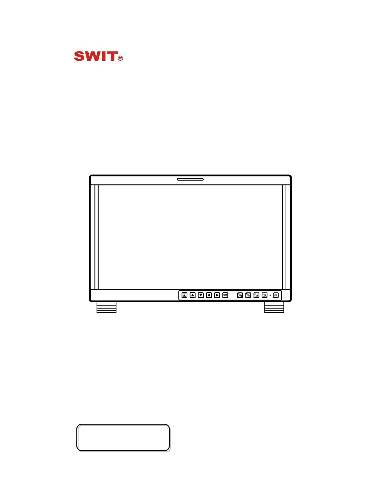
Model: FM-17
17.3" FHD Production Monitor
User Manual
Ver: A
SWIT Electronics Co., Ltd.
Please read this User M anual
throughout before using.
Page 2

Preface
1. All internal technologies of this product ar e pr ot ect ed, includ ing device, software and
trademark. Reproduction i n whole or in part without w r itten permission is prohibited.
2. All brands and trademarks of SWIT Electronics Co., Ltd. are protected and other
relative trademarks in this us er manual are the property of t heir r espective owners.
3. Due to constant effort of product development, SWIT reserves the right to make
changes and improvements to the product described in this manual without prior
notice.
4. The warranty period of this pr oduct is 2 years, and does not cover the following:
⑴ Physical damage to the surface of the products, including scratches, cracks or
other damage to the LCD screen or other externally exposed parts;
⑵ The LCD dot defects are not over three;
⑶ Any damage caused by using third-party power adaptors;
⑷ Any damage or breakdown caused by use, maintenanc e or st or age not according
to the user manual;
⑸ The product is disass embled by anyone other than an authorized service center ;
⑹ Any damage or breakdown not caused by the product design, workmanship, or
manufacturing quality, et c ;
*Any sales personnel ha ve no rights to provide ad ditional warranty.
5. For any suggestions and requirements on this product, please contact us through
phone, fax, Email, etc.
SWIT Electronics Co., Ltd.
Address: 10 Hengtong Road, Nanjing Economic and Technological Development Zone,
Nanjing 210038, P.R. China
Phone: +86-25-85805753
Fax: +86-25-85805296
Email: contact@swit.cc
Website: http://www.swit.cc
Page 3

Maintenance
Warning
1. In order to reduce the risk of fire and electrical shock, do not lay this product in
rain or damp places.
2. Please keep away from the strong magnetic field; it may cause the noise of the
video and audio signals.
The power
1. Please use the power adapter provided or recommended by the manufacturer in
order to avoid damage.
2. For a third party power adapter, please make sure the voltage range, supplied
power , and polarity of power lead are fit.
3. Please disconnect the power cable under the following situat ions:
(A). If you do not operate this monitor f or a per iod of time;
(B). If the power cable or power adaptor is damag ed;
(C). If the monitor housing is broken.
The monitor
1. Please don't touch the screen with your fingers, which would probably deface the
screen.
2. Please don't press the screen; t he LCD is extremely exquisite a nd flimsy.
3. Please don't lay this product on unstable place.
Cleaning
1. Please clean the screen with dr y and downy cloth or special LCD c lea nser.
2. Please do not press hard when cl eaning the screen.
3. Please do not use water or other chemical cleanser to clean the screen. The
chemical may damage the LCD.
Page 4

Contents
Preface .....................................................................................................................................................2
Maintenace ..............................................................................................................................................3
Contents ...................................................................................................................................................4
1.Packing List ...........................................................................................................................................4
2.Installation Dimensions .........................................................................................................................5
3.Installation instruc t io ns of accessories .................................................................................................6
4.Operation Instructions .........................................................................................................................12
5.Functionality of the Main Menu. ..........................................................................................................19
6.Specification ........................................................................................................................................51
1.Packing List
Stan dard Pac kage:
Optional accessries
1. Battery plate (V-mount)
2. Desktop Stand Feet
3. Sun hood
4. Protective Glass
5. Power cable
1. C-Stand
2. Hanger
Features:
17.3-inch, 1920x1080, 8-bit LCD, 12-bit process
3G/HD/SD-SDI, HDMI, CVBS monitoring
Built-in multi camera s De-log LUTs and DIT LUTs upload by USB
Waveform / Vector / Histogram / 16-ch Audio meters / Timecode
Peaking / Focus assist / Exposure assist / Zebra / Bl ue only
Anamorphic de-squeeze / Multiple markers
Portable, light weight and C-stand setup
Page 5

2. Installatio n D im e ns ion
Front Panel
Side View
Rear Panel
Top View
Page 6
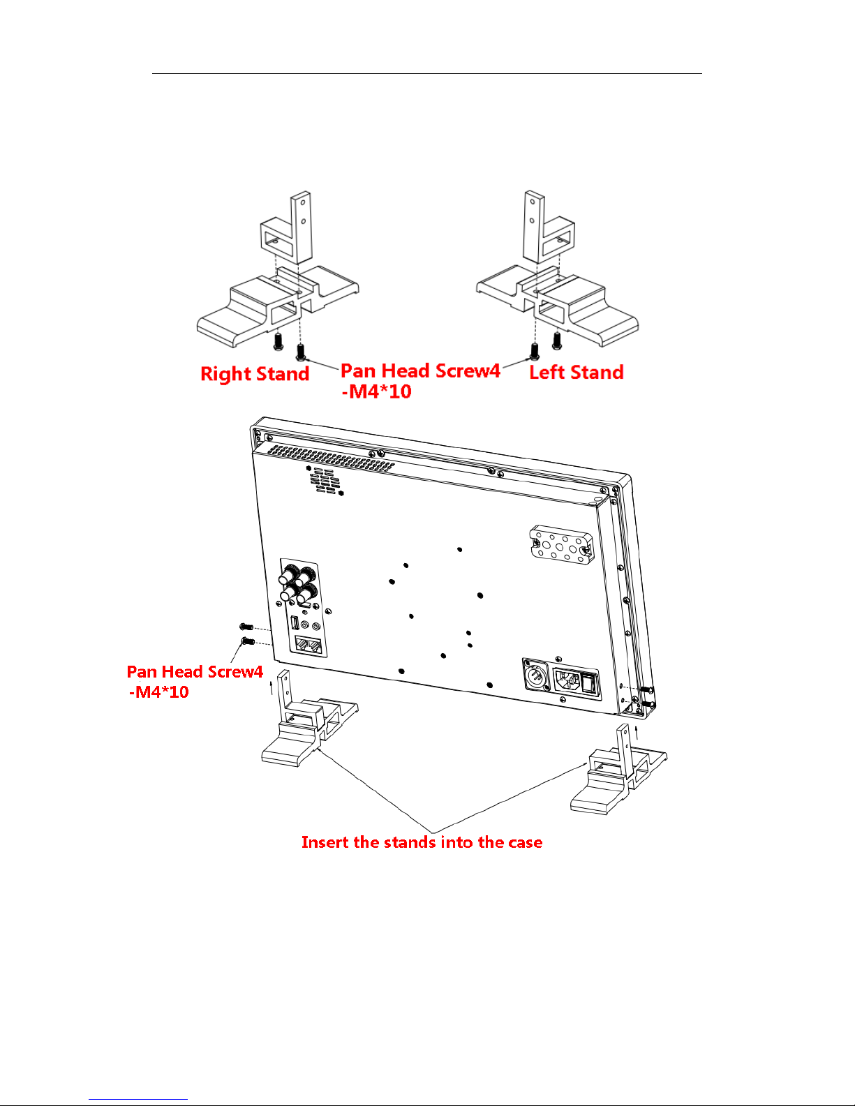
3. Installation instructions of accessories
Desktop Sta nd Feet
Page 7
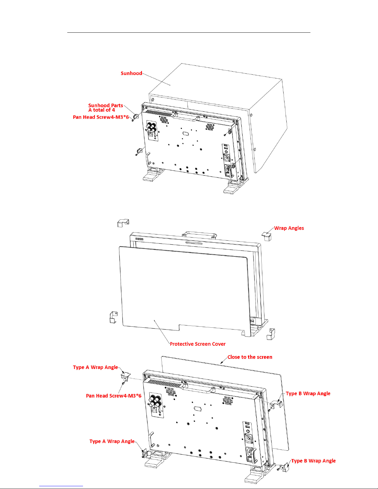
Sun hood
Protective Glass
Page 8
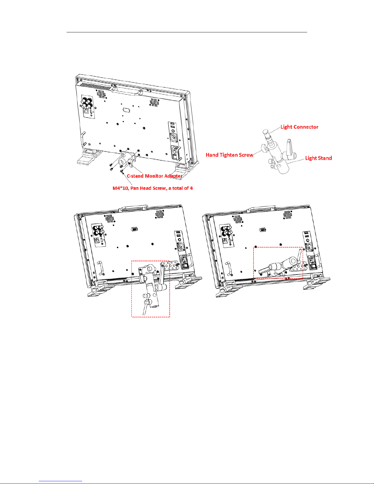
C-Stand
Page 9
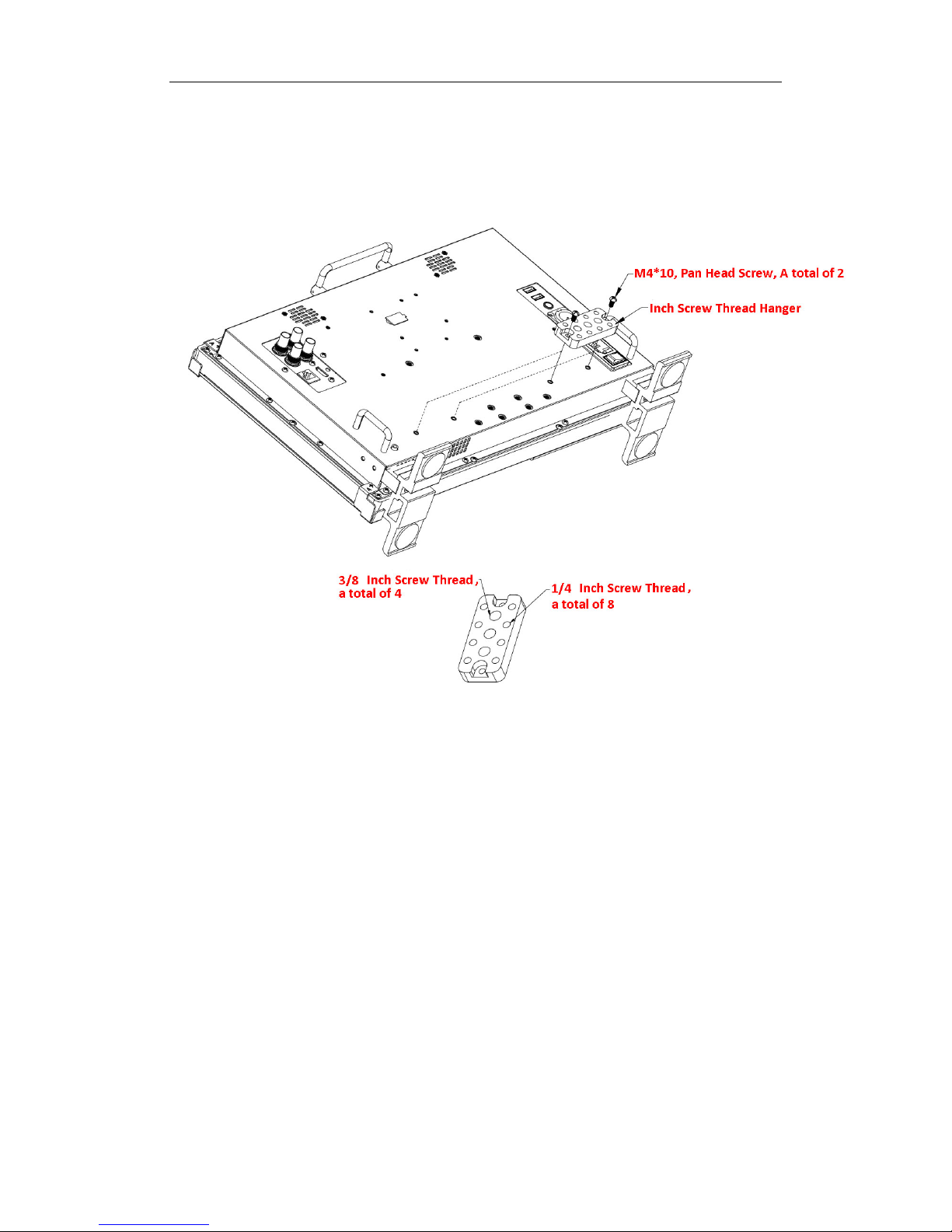
Hanger
It provides an inch screw thread hanger as an optional accessory. The hanger provides
two sorts of screw thread: 3/8 inch screw thread, a total of 4; 1/4 inch screw thread, a
total of 8.
Page 10
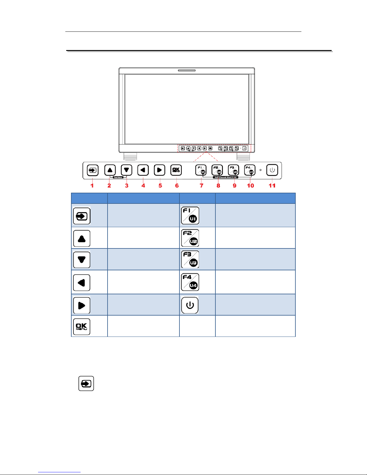
4. Operation Instructions
BUTTON
FUNCTION
BUTTON
FUNCTION
Input selection Function button F1
Adjust upward Function button F2
Adjust downward
Function button F3
Return/Exit Function button F4
Select next Power on/off
Save/Return/Main menu
All of these buttons have light ind icators.
4.1 Operation of Front Panel
The functionality and usage of the buttons at the front panel are as follows:
: Input Selection
Select the input signal from each input interface. Press this button to display the
input source menu at the top right corner of the screen, as shown in Figure 1. Use it
to select an input signal source, pr ess it again to toggle among these input signal
items, or after the input source menu displayed, use the UP or DOWN button to
Page 11
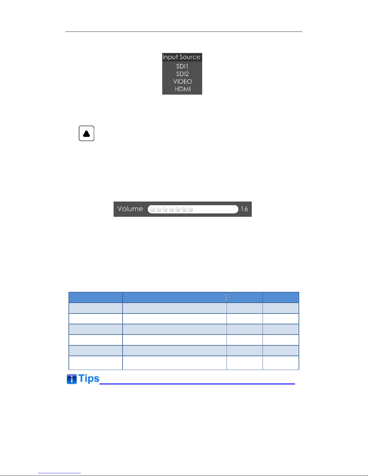
toggle among these input sign al items.
Figure 1 Source Menu
: UP ARROW
It is UP button when working with the main menu. Toggle this button to select
the next item or increase the nu mb er.
Without the Main menu: when not displaying the Main menu, press
LEFT
button to display the
Fast Menu
list, as shown in Figure 2, toggle among these
menu items:
Volume, Brightness, Contrast, Saturation, Backlight
and
Sharpness
.
Figure 2 Fast Menu List
After displaying the
Fast Menu
, press
LEFT
or
RIGHT
arrow button to adjust t he
menu value.
The limitations of these it ems are shown in Table 4.1-1:
Table 4.1-1 The Description of Fast Menu Items
Adjust Menu
Description
Range
Default
Volume
Adjust the volume
0~31
16
Brightness
Adjust the image brightness
0~100
50
Contrast
Adjust the image contrast
0~100
50
Saturation
Adjust the image color intensity
0~100
50
Backlight
Adjust the backlight
0~10
5
Sharpness Adjust the image sharpness
0~63
8
After you have loaded the adjust menu list, it will be clos ed aut omatically if you do
nothing operation on it within t he
Osd Time
.
The main menu, the fast menu, t he function menu and the i nput sign al selecti on list of
a screen may not be shown all s i mu ltaneously.
Page 12

: DOWN ARROW
It is
DOWN
button when working with the main menu. Toggle this button to
select the next item or decr ease t he number.
Without the Main menu: when not displaying the Main menu, press
DOWN
button to display the
Fast Menu
list, refer to the details in the above description
as in UP arrow button.
: LEFT ARROW
Press this button to do the follow ing operations:
With the Main menu: when working with the Main menu, LEFT button achieve
the following functions:
Back to the higher level menu
B ack to the higher level menu and not save the setting of the menu item
value
Quit the Main menu
With the Fast menu: when displaying the Fast menu, press
LEFT
button to
decrease the item value.
: RIGHT ARROW
Press this button to do the follow ing operations:
With the Main menu:
Enter into the next level menu.
Turn Page: when the current selection in the sub-menu list is
Next Page
,
press this button to turn to the next page circularly.
With the Fast menu: when displaying the Fast menu, press RIGHT button to
increase the item value.
OK/MENU
It is used to activate the Main menu. Pr ess this button to do some operat ions with
the Main menu, it includes the fol lowing operations:
Display the Main menu: press
OK/MENU
button, it will display t he main menu at
the center of the screen.
Page 13

Save/Back: confirm the selection and back to the higher level menu.
Turn Page: when the current selection in the sub-menu list is
Next Page
, press
this button to turn to the next page circularly.
F1/U1
This button is a
FUNCTION
and
User Preset
button.
F1 function:
The F1 function can be assigned via the CONFIG menu. Press
the function button to activate or deactivate the assigned function. Press F1 to
display the function menu list in the center of the screen, as shown in Figure
4.1-4. Toggle F1 button to change the value related to this function.
Figure 4.1-1 Function Menu List
USER1:
Switch to
User Preset USER1
directly. Hold 2 seconds to select the
current user preset to be User1. The name of the current user preset will be
prompted on the left center of the screen. Refer to “5.1.4.1 FUNCTION KEY
and User Preset Menu” for t he set ting of
User Preset.
If the value related to the function but t on c an’t be modified, the value shows in gray.
For
F2/U2~F4/U4
function buttons, t he oper at ions are as the same as F1/U1' s.
Use
FUNCTION KEY
menu to assign F1~F4. You can assign the function from
among: Camera LUT, Undef, Blue Only, Mono, Marker, Audio Meter, Time Code,
Wavefor m T ype, Vectorscope, Histogram, Scan, Aspect, Native, Mute, IMD Display,
False Color , Focus Assist, Peak, Zebra. Refer to "5.1.4 USER CONFIG Menu " for the
details.
Power
Used to power on or st andby, and the light in the button will ind icate th e st at us of the
power . When the monitor is powered on, t he lig ht is green, press the power but ton
and hold 2 seconds, it will enter int o standby mode, the light is red.
4.2 Rear Panel Features
It will introduce the arrangement and the operations of the interfaces in rear of the panel
in the following.
Page 14
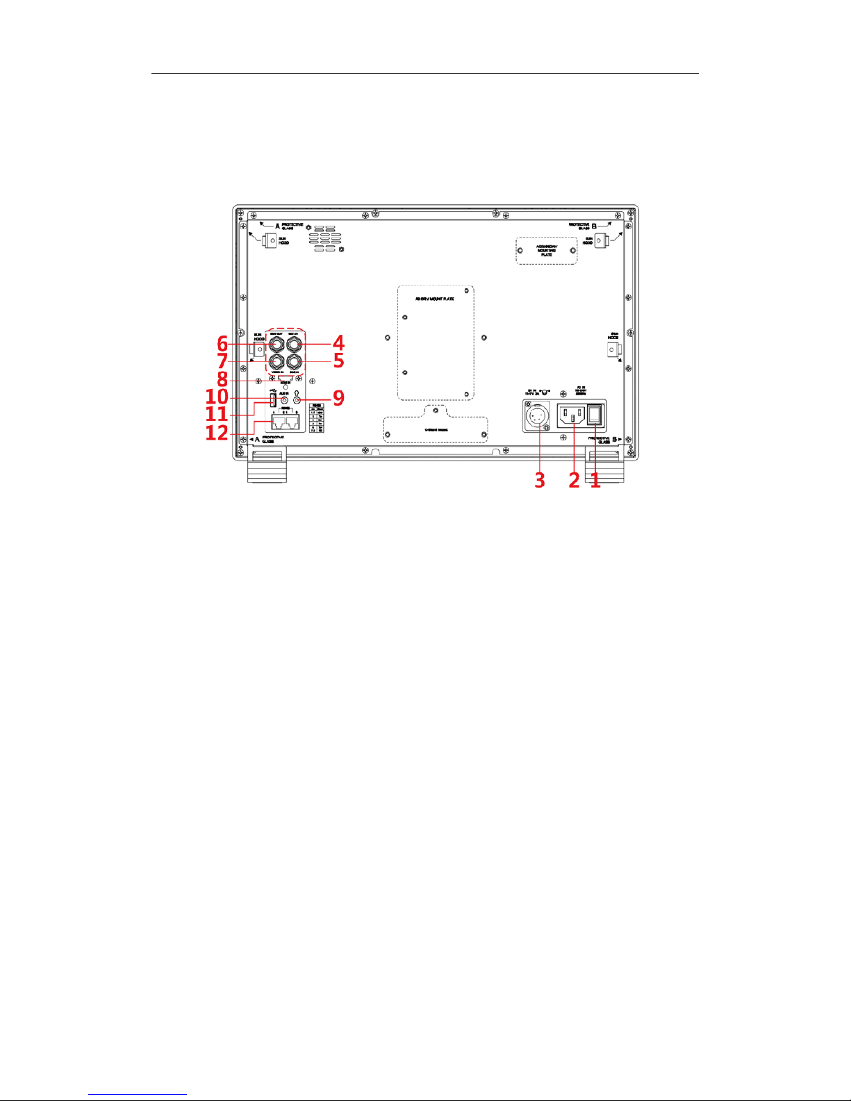
Arrangement of Rear Panel
For the arrangement of the r ear panel of FM-17 is shown in Figure 4.2-1, there are
various input and output inter fac es at the rear panel, and bui ld-in speakers in the
top.
Figure 4.2-2 The Rear Panel of FM-17 Monitor
The interfaces numbered in r ed ar e described as follows:
1. Power Switch
2. AC Power Input
3. DC Power Input
4. Video Input: SDI 1 I N
5. Video Input: SDI 2 I N
6. Video Output: SDI1 OUT
7. Video Input: VIDEO IN
8. HDMI Input: HDMI IN
9. Headphone
10. Audio Input: AUD IN
11. USB
12. RS485 X2
Page 15
Operations of Rear Panel
The details of these interfaces at the rear pane l are described as follows:
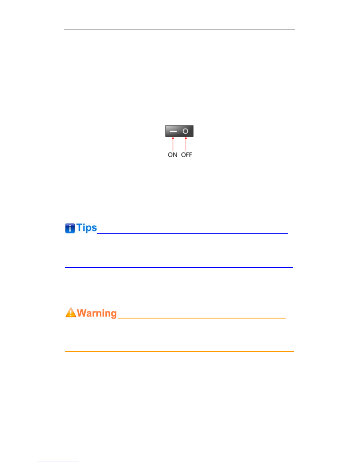
Power Switch
It provides one power switch to switch on or switch off. As shown in Figure 4.2-2,
push the button to the direction “-” to switch on the power, or push the button to the
direction “O” to switch off the power.
Figure 4.2-3 Power Switch
AC Power Input
It provides one AC power input interface, the specification is 100 ~
240V50/60HzAC.
The power indicator is on the pow er but t on at the front panel. If the light is green, the
monitor is powered on, and if the lig ht is r ed, t he monitor is standby.
DC Power Input
It provides one DC power input interf ac e, t he specification is 11~17V3A DC.
Only use the adapter and the pow er cor d specified by the manufacture for your
safety!
Video Input Interface ( B NC) SDI1 IN~SDI2 IN
It provides two SDI input inter faces, labeled as SDI1 IN, SDI2 IN.
Video Output Interfa ce ( BNC) SDI1 OUT
It provides one SDI output interface, labeled as SDI1 OUT.
Video Input(BNC): VIDEO IN
Page 16

HDMI Input: HDMI IN
It provides one HDMI input inter face, HDMI Type-A connect or with a fastener.
Audio Output(3.5mm jack): it provides one headphone.
Audio Input(3.5mm jack): AUD IN, it provides one audio input interfa ce .
USB: it is used for LUT input and firmware upgrading.
RS485 Interface (RJ-45)
It provides two RS485 interfaces, loop out. Support for cascade connection and
IMD remote control. The comparison of pins and Input connectors for RS485 is
shown as in Table 4.2-1:
Table 4.2-2 The Comparison of Pins and Input connectors for RS485
PIN No.
RS485 IN Terminal Sign al
1,2
GND
3
Tx- 4 Rx+
5
Rx-
6
Tx+
7,8
NC
Supported Signal Format
The supported signal format for t his device is as shown in Table 4.3-1:
Table 4.3-1 Supported Signal Format
Signal SDI HDMI VIDEO
NTSC
PAL
SD
480I60
4:2:2 YCbCr 10 BIT
576I50
Page 17

Signal SDI HDMI VIDEO
HD
720P24/23.98
720P25
720P30/29.97
720P50
720P60/59.94
1080SF24/23.98
1080SF25
1080SF29.97
1080SF30
1035I60/59.94
1080I50
1080I60/59.94
1080P24/23.98
1080P25
1080P30/29.97
3G
1080I50
4:2:2 YCbCr 12 BIT
4:4:4 YCbCr 10 BIT
4:4:4 YCbCr 12 BIT
4:4:4 RGB 10 BIT
4:4:4 RGB 12 BIT
4:4:4_XYZ_10BIT
4:4:4_XYZ_12BIT
1080I60/59.94
1080P24/23.98
1080P25
1080P30/29.97
1080P50
4:2:2 YCbCr 10 BIT
1080P60/59.94
3G-2K
1080SF24/23.98
4:2:2 YCbCr 12 BIT
4:4:4 YCbCr 10 BIT
4:4:4 YCbCr 12 BIT
4:4:4 RGB 10 BIT
4:4:4 RGB 12 BIT
4:4:4_XYZ_10BIT
4:4:4_XYZ_12BIT
1080SF25
1080SF29.97
1080SF30
1080P24/23.98
1080P25
1080P30/29.97
1080P48/47.95
4:2:2 YCbCr 10 BIT
1080P50
Page 18

Signal SDI HDMI VIDEO
1080P60/59.94
Page 19

5. Functionality of the Main Menu
This chapter describes the structure and functionality of the main menu, and introduces
how to modify and customize t he me nu settings.
The main menu includes the following menu it ems, as shown in Figure5-1.
Figure 5-1 Main Menu
Main Menu
Press the OK/MENU button at the bott om of the front pane l, the main menu is disp layed at
the center of the screen, as shown i n Figure 5.1-1:
Figure 5.1-1 the Structure of the Main Menu
Page 20

The menu interface is divided i nt o t hr ee parts:
Main Menu List
It contains the menu list of the Main menu. Press UP or DOWN to access the
corresponding menu item.
Sub-menu list
Press right arrow button to enter into the next level of menu list, as show n in Figure
5.1-2, it lists the title of the Sub-menu, the sub-menu item and the value o f the item .
Then, press arrow buttons and OK/MENU button to modify the value of the
sub-menu.
Figure 5.1-2 the Sub-menu Value List
Control Icon
There is a white control icon when you select the menu or its value in the sub-menu
list.
Next Page Selection
There is a white control icon when you select the menu or its value in the sub-menu
list.
When there are more than one page items in a menu list, t her e w ill be a
Next Page
item at the first line in every pages. Press right arrow button or press the
OK/MENU
button to turn page.
The sub-menu item is selected w hen t he control icon which is in white highlight is at
the back of the item name.
Page 21

The following will introduce the contents and functionality of these sub-menu items in
sorts.
STATUS Menu
The STATUS menu ite ms ar e us ed t o describe the current status information of the
monitor , t he menu items are as shown in Figure 5.1-3:
Figure 5.1-3 STATUS Menu
There are two pages in
STATUS
menu. The relationship of Items, Default Value,
Domain Range and Descript io n of the sub-item is shown in Table 5.1-1:
Table 5.1-1 The Description of STATUS Menu Items
Items
Default Value
Description
Page1
Input
SDI1 1080I50
Show the input interface and its format
Signal Format
4:2:2 YCbCr 10 BIT
Show the format of the inp ut signal
Color Range
64~940
Show current color range
YCbCr Color Matrix
ITU-R BT.709
Show YCbCr color matrix
Gamma
2.2
Show Gamma
Color Temp
D65
Show color temperature
Color Space
P3
Show color space
Camera LUT T ype
Camera SDR
Show the type of camera LUT
User Preset
USER1
Show the user preset nam e
Page2
Page 22

Items
Default Value
Description
Model
--
Show the production mod el.
Serial Number
--
Show the serial number.
Firmware V ers ion
--
Show the firmware number.
The sub-menu values in
STATUS
menu can’t be modifie d, t hey are displayed the
actual status of the mon itor .
INPUT CONFIG Menu
The INPUT CONFIG me nu items are used to set the source o f the i nput signals, the
menu items are as shown in Figure 5.1-4:
Figure 5.1-4 INPUT CONFIG Menu
There is one page in
INPUT CONFI G
menu. The relationship of It ems, Default Value,
Domain Range and Descript io n of the sub-item is shown in Table 5.1-2:
Table 5.1-2 The Description of INPUT CONFIG Menu Items
Items
Default
Value
Domain Range Description
Page1
SDI IN1
ON
ON/OFF
Enable/Disable SDI1 input
SDI IN2
ON
ON/OFF
Enable/Disable SDI2 input
Page 23

Items
Default
Value
Domain Range Description
VIDEO
ON
ON/OFF
Enable/Disable VIDEO input
HDMI
ON
ON/OFF
Enable/Disable HDMI input
NTSC Phase 0 -50~50
Set the NTSC phase level, and
this item is available only when
NTSC format signal is input .
Signal Format
Auto
As shown in Table 5.1-3
signal format for the inputs
Color Range
64~940
64~940
64~1023
0~1023
Set color range
YCbCr Color
Matrix
Auto
Auto
ITU-R BT.709
ITU-R BT.2020
Set YCbCr color matrix
1. Signal Format Setting
The device provides four inputs: SDI IN1, SDI IN2. Set the input format through
INPUT CONFIG Signal Format
menu item.
Table 5.1-3 The Relationship of Signal Format and Signal Type
Signal Type
SDI
HDMI
Signal Format
AUTO
4:2:2 YCbCr 10 BIT
4:2:2 YCbCr 12 BIT
4:4:4 YCbCr 10 BIT
4:4:4 YCbCr 12 BIT
4:4:4 RGB 10 BIT
4:4:4 RGB 12 BIT
4:4:4 XYZ 10 BIT
4:4:4 XYZ 12 BIT
AUTO
4:4:4 XYZ 10/12 BIT
COLOR MANAGEMENT Menu
The COLOR MANAGEMENT menu items are used to adjust the color tempera ture
parameters and the col or bal ance, the menu items are as shown in Figure 5.1-5:
Page 24

Figure 5.1-5 COLOR MANAGEMENT Menu
There are two pages in
COLOR MANAGEMENT
menu. The relationsh ip of Items,
Default Value, Domain Range and Description of the sub-item is shown in Table
5.1-4:
Table 5.1-4 The Description of COLOR MANAGEMENT Menu Items
Items
Default
Value
Domain Range Description
Gamma 2.2
1.8/2.2/2.4/2.6/2.8/
BT.1886/PQ/HLG
Adjust Gamma
Color Temp D65
D93/D65/D61/D55/
DCI/USER1/USER2
Set the color temperature
Red Gain
512
0~512
Adjust the Red Gain
Green Gain
512
0~512
Adjust the Green Gain
Blue Gain
512
0~512
Adjust the Blue Gain
Copy From D65
D93/D65/D61/D55/
DCI
Copy this parameter value to
USER
Reset -- --
Reset the Gain and Of fset values t o
the product originals
Color Space EBU
Native
SMPTE-C
EBU
ITU709
ITU2020
P3
Set the color space for the first
channel
Page2
Camera LUT
ON
ON/OFF
Enable/disable camera LUT
Page 25

Items
Default
Value
Domain Range Description
Camera LUT
Type
Camera
SDR
Camera SDR
Camera HDR
User
Set a LUT from the corresponding
list
Camera SDR
2.2
Refer to Table 5.1-5
Load the selected SDR LUT
Camera HDR
---
Refer to Table 5.1-5
Load the selected HDR LUT
User
User1
User1~User16
Load a customized LUT file
Load LUT File
---
---
To load a LUT file from the U disk
Camera LUT
The LMW-173 supports multiple camera L UTs, as shown in Table 5.1-5:
Table 5.1-5 The Relationship Between EOTF and HDR
Camera LUT
LUT Name
Company
SDR
ARRI_LogC_Rec709
ARRI
BMD_4.6KFilm_Rec709
BlackMagic
BMD_4.6KFilmV3_Rec709
BMD_4KFilm_Rec709
BMD_4KFilmV2_Rec709
BMD_4KFilmV3_Rec709
BMD_CCFilm_Rec709
BMD_CCFilmV2_Rec709
Canon_CLog1Cine_Rec709_FF_V1.1
Canon
Canon_CLog2Cine_Rec709_FF_V1.1
Canon_CLog3Cine_Rec709_FF_V1.1
DJI_Phantom3DLog_Rec709_Improv
DJI
DJI_Phantom4DLog_Rec709
DJI_Phantom4Dlog_Rec709_Improv
DJI_X5DLog_Rec709_Improv
FUJI_FLogFGamut_FLogRec709_V1
FUJIFILM
FUJI_FLogFGamut_WDRRec709_V1
GoPro_Protune_Rec709
GoPro
JVC_JLog1_Rec709_Daylight
JVC
JVC_JLog1_Rec709_Tungsten
Panasonic_VLog_V709_V1
Panasonic
RED_L3G10RWG_Rec709_ R1_V1.13
RED
Page 26

Camera LUT
LUT Name
Company
RED_L3G10RWG_Rec709_ R2_V1.13
RED_L3G10RWG_Rec709_ R3_V1.13
RED_L3G10RWG_Rec709_ R4_V1.13
RED_RedLogFilm_RG3
Sony_SLog2SGamut_LCRec709
Sony
Sony_SLog2SGamut_LCRec709A
Sony_SLog3SG3Cine_LCRec709
Sony_SLog3SG3Cine_LCRec709A
HDR
ARRI_LogC_HLG_Rec2020
SWIT
ARRI_LogC_PQ_Rec2020
Canon_Clog2Cin_HLG_Rec2020
Canon_Clog2Cin_PQ_Rec2020
Canon_Clog3Cin_HLG_Rec2020
Canon_Clog3Cin_PQ_Rec2020
Panasonic_VLog_HLG_Rec2020
Panasonic_VLog_PQ_Rec2020
RED_L3G10_HLG_Rec2020
RED_L3G10_PQ_Rec2020
Sony_SLog3_Cin_HLG_Rec2020
Sony_SLog3_Cin_PQ_Rec2020
Sony_SLog3_SG3_HLG_Rec2020
Sony_SLog3_SG3_PQ_Rec2020
When setting Camera LUT Type item as Camera SDR, Camera HDR or User, the
following corresponding Camera SDR, Camera HDR, User item will be activated,
and the available ranges of Ga m m a ar e diverse, as shown in the following table:
Camera LUT Type
Gamma
Camera SDR
1.8/2.2/2.4/2.6/2.8/BT.1886
Camera HDR
PQ/HLG
User or OFF
1.8/2.2/2.4/2.6/2.8/BT.1886/PQ/HLG
Load a user LUT from disk
First, load a LUT file to t he designated user LUT. Set
COLOR Management Load
LUT File
, it will pop up the
USB LUT Files
selection w indow as shown in
Figure 5.1-6.
Select
USER
item, and when detecti ng USB disk, it w ill pop up a file selection w indow,
press the arrow button to selec t a LUT file, press
OK/MENU
button to confirm the
Page 27

selection, and it will pop up a USER file selection window, press the arrow button to
choose from
User1~ User16
to set the storage path for t he selected LUT. For
example, select
User1
, and press
OK/MENU
button to confirm the set ting.
Figure 5.1-6 USB LUT Files
Second, power off the d evice, and restart it to affect the settings abov e.
At lase, set
COLOR Managem e nt Camera LUT
as
User
item, and set
COLOR
Management
User
as
User1
selected as above. The LUT file w i ll take effect.
Make sure to restart t he device to effect the selected user LUT file af t er loading it to a
designated user LUT thr ough the USB disk.
The items about RED/GR EE N/BLUE GAIN are available on ly in USER1 and USER2
mode. If the COLOR TEMP is set to
USER1
or
USER2
with customized sett ings, you
can select the menu item
COLOR TEMP
RESET
command to restore product
originals for Gains, and press
OK/MENU
button to confirm the reset operation.
USER CONFIG Menu
The USER CONFIG men u items are used to adjust the p ar ameters defined by
customers, the menu items are as show n in Figure 5.1-7:
Page 28

Figure 5.1-7 CONFIG Menu
There are six pages in
USER CONFIG
menu. The relationship o f Items, De fault Value,
Domain Range and Descript io n of the sub-item is shown in Table 5.1-6:
Table 5.1-6 The Description of USER CONFIG Menu Items
Items
Default
Value
Domain Range Description
Page1
User Preset USER1
USER1/USER2/
USER3/USER4
Set the settings as a user
preset
F1 Button Scan
Camera LUT/Undef/
Blue Only/Mono/
Marker/Audio Meter/
Time Code/
Wavefor m T y pe/
Vectorscope/Histogram/
Scan/Aspect/Native/
Mute/IMD Display/
False Color/
Focus Assist/
Peak/Zebra
Assign a function to F1
button
F2 Button Marker the same as F1
Assign a function to F2
button
F3 Button Audio Meter the same as F1
Assign a function to F3
button
F4 Button Blue Only the same as F1
Assign a function to F4
button
Page2
Audio Source
EBD
EBD: embedded
Select the audio source.
Page 29

Items
Default
Value
Domain Range Description
signal
EXT: external signal
OFF: no signal
Speak Out L EBD CH1
When the audio source is
EBD, the range of this item
is EBD CH1~ E BD CH16.
Left speaker, select a
channel according to the
type of audio source.
Speak Out R EBD CH2
When the audio source is
EBD, the range of this item
is EBD CH1~ E BD CH16.
Right speaker, select a
channel according to the
type of audio source.
Meter Display OFF OFF/ON
Set whether to display the
audio meter .
Meter Select CH1-2
CH1-2/
G1/G2/G3/G4/
G1+G2/G1+G3/
G1+G4/G2+G3/
G2+G4G3+G4/
G1-G4
Select a meter display
mode. Each G* contains
four channels
, and each
CH* means a channel with
number.
Meter Position LEFT LEFT/RIGHT
Select the displayed
position of audio meter.
Display Mode Mode1
Mode1: simple audio meter
Mode2: audio meter with
channel number and fram e
Used to set the displayed
mode for audio meter .
Meter Opacity 0
0: 100%
1: 50%
Set the transparency for
audio meter .
Page 3
Marker OFF OFF/ON
Set whether to show all of
the markers. It is the main
switch for area marker,
center marker and safety
marker.
Aspect Marker OFF
16:9
4:3
15:9
14:9
13:9
1.85:1
2.35:1
Variable
OFF
Select the aspect marker
according to the display
aspect ratio.
Var iable Aspect 3.00
1.00~3.00, the step is 0.01
When set the Aspect
Marker as Variable, set the
aspect ratio at this item
Center Marker OFF OFF/ON
Set whether to show the
center marker
Area Marker OFF
OFF
Set the safety area size
Page 30

Items
Default
Value
Domain Range Description
80%
85%
88%
90%
93%
95%
according to the aspect
ratio and scan mode.
Marker Fit OFF
OFF: the safety
marker is based on
the current input
source
ON: the safety
marker is based on
the image within the
current aspect
marker
Whether to set connection
between Aspect MARKER
and Safety Marker.
Marker Level 1
1: 50%
2: 75%
3: 100%
Set the luminance of
marker line, including
safety marker, center
marker, area marker and
cross hatch.
Marker Mat OFF
OFF: Normal
background, use
line for area marker
edge only
HALF: 50%
Background
brightness
BLACK: all black
Darkens the outside of the
area of the Aspect
Marker, and set its
transparency.
Cross Hatch OFF OFF/ON
Set whether to show the
cross hatch.
Page 4
Wavefor m T y pe OFF
WAVEFORM
VECTOR
WFM WIDE
HDR WFM
OFF
Set the display type of
WFM
Waveform Size Small Small/Middle/Large
Set the waveform display
size
Waveform
Location
TOP RIGHT
Small: Left
Up/Center Up/Right
Up/Right
Center/Right
Down/Center
Down/Left
Down/Left Center
Set the location of the
waveform
Page 31

Items
Default
Value
Domain Range Description
Middle: Right
Down/Center
Down/Left Down
Small: Center Down
Vectorscope OFF OFF/ON
Enable/Disable
vectorscope display
Vectorscope
Location
TOP RIGHT
Left Up
Center Up
Right Up
Right Center
Right Down
Center Down
Left Down
Left Center
Set the location of the
vectorscope
Histogram OFF OFF/LUMA/RGB
Enable/Disable histogram
display, and set the
histogram mode
Histogram
Location
TOP RIGHT
Left Up
Center Up
Right Up
Right Center
Right Down
Center Down
Left Down
Left Center
Set the location of the
histogram
Opacity 0
0: 100%(opaque)
1: 75%
2: 50%
3: 25%
Set the transparency of
WFM, vectorscope and
histogram
Page 5
Focus Assist OFF
OFF
GRA Y: Turn the
image into gray
mode, and displays
the edge of images
with color selected
in FOCUS COLOR.
COLOR: Displays
the edge of images
with color selected
in FOCUS COLOR.
Enable/Disable the focus
assist function, and set
focus assist mode.
When the difference of the
edges exceeds the
reference value (FOCU
S
LEVEL), the edge detected
will be in colorful feature
set by FOCUS COLOR.
Focus Assist
Color
Red Red/Green/Blue
Set the color for the
detected edge of images.
Focus Assist
50
0~100
Set the edge difference
Page 32

Items
Default
Value
Domain Range Description
Level
value between the edges in
an image, an
d take this
value as the reference
value. Larger value means
more detail detection.
Peak OFF ON/OFF
Enable/Disable peak
function. Over sharpen the
image.
Peak Level 1 1~8
Set the sharpness level of
the image. The higher the
value, the sharpener the
image.
False Color OFF OFF/ON
Enable/Disable false color
function
False Color Ty pe Spectrum
Spectrum/SONY Slog3/
SONY Slog2/ARRI LogC/
Canon Clog2/
Canon Clog3/
Panasonic Vlog/
RED RedLogF ilm/
RED RL3G10/
BMD/BMD 4K/
ARRI Rec709/
SONY LC709A/
SONY LC709/
Panasonic V709/
RED G3/RED G 4
Set the type of the false
color display
Zebra OFF ON/OFF
Enable/Disable the zebra
function that will compare
the signal luminance with
the ZEBRA LEVEL, and fill
the relevant image area
whose luminance is higher
than the ZEBRA LEV
EL
with a zebra pattern.
Zebra Level 50 0~100
Set the reference level of
detecting luminance.
Page 6
Internal Signal OFF OFF/ON
Enable/Disable the internal
color bar
OSD Time ON ON/10s/30s/60s
Set the display time of the
OSD menu
Time Code OFF OFF/ON
Enable/Disable time code
display
Status Display OFF OFF/ON/AUTO
Set the display time of the
Status infor mation menu
Language ENGLISH
ENGLISH/中文
Select a language mode
Page 33

Items
Default
Value
Domain Range Description
Monitor Reset -- --
Set whether to restore the
factory settings
Firmware
Upgrade
-- -- Upgrade the firmware
FUNCTION KEY and User Preset Menu
1. User Preset
The user preset provides a ser ie s of me nu set tings customized as a User P r eset, up
to 4 presets could be defined in this device.
Set
USER CONFIGUser Preset
as User1, User2, User3 or User4 to switch among
these various preset settings for current menu displa y. Or press
~
button
and hold 2s to select the related us er presets, and there will be a prompt displaying
the current user preset name at t he l eft center of the screen.
The FUNCTION KEY menu items(F1 Button~F4 Button) are used to assign function
to the function key (F1~F4) on t he front panel, and adjust the v alu e of the function
parameter. The menu items of FUNCTION KEY are as shown in Table 5.1-7:
Table 5.1-7 Functionalities for the Function Key
Items
Default
Value
Range Description
Camera LUT
OFF
OFF/ON
Enable/Disable Camera LUT
Blue Only
OFF
OFF/Red/Green/Blue
Enable/Disable blue only
Mono
OFF
OFF/ON
Enable/Disable Mono
Marker OFF OFF/ON
Enable/Disable the master marker
switch
Audio Meter OFF OFF/ON
Enable/Disable audio meter
display
Time Code
OFF
OFF/ON
Enable/Disable time code display
Waveform
Type
OFF
LUMA/RGB/
PARADE/OFF
Set the waveform type
Vectorscope OFF OFF/ON
Enable/Disable Vectorscope
display
Histogram
OFF
OFF/LUMA/RGB
Enable/Disable Histogram display
Scan
OFF
Normal/Over
Enable/Disable scan function
Aspect
---
As shown in Table 5.1-8
Set aspect ratio
Native OFF OFF/Left/Center/Right
Enable/Disable native function,
and set its mode
Mute
OFF
OFF/ON
Enable/Disable mute
IMD Display
OFF
OFF/ON
Enable/Disable IMD displ ay
Page 34

Items
Default
Value
Range Description
False Color OFF OFF/ ON
Enable/Disable false color
function
Focus Assist OFF
OFF/Mono/
Focus Assist Color
Enable/Disable Focus Assist
function and set its mode
Peak
OFF
OFF/ON
Enable/Disable Peak
Zebra
OFF
OFF/ON
Enable/Disable Zebra
2. ASPECT
Set the aspect ratio of the screen, it is different from t he formats of the input signals,
and the details are as sho w n in Table 5.1-8:
Table 5.1-8 The Relationship of Input Signal For m at s and Its Aspect s
Input
Signal
Default Value Range Input Signal Formats
SD 4:3
4:3
16:9
480I60
576I50
HD 16:9
16:9
2.39:1
720P24/23.98
720P25
720P30/29.97
720P50
720P60/59.94
1080SF24/23.98
1035I60/59.94
1080I50
1080I60/59.94
1080P24/23.98
1080P25
1080P30/29.97
1080P50
1080P60/59.94
2K 1.896:1
1.896:1
2.39:1
2048X1080PSF24/23.98
2048X1080PSF25
2048X1080PSF30/29.97
2048X1080P24/23.98
2048X1080P25
2048X1080P30/29.97
2048X1080P48/47.95
2048X1080P50
2048X1080P60/59.94
3. Mute
Active this function to adjust t he volume to 0, press the function butt on again to
release the volume to the last v alue.
4. BLUE ONLY
It is to activate BLUE ONLY mode that will remove colors from the i nput signal and
display the screen only under a r ed, gr een or blue signal.
5. MONO
It is to activate MONO mode that w ill displ ay t he screen in m onochr om e prese nt atio n,
inactivate this mode to display t he s cr een in color mode.
Press F1~F4 button to activate the assigned function and adjust the parameter value.
Page 35

AUDIO Menu
The AU DI O m enu items are displayed on Pag e2 in
USER CONFI G
menu, and they
are used to adjust the audio parameters:
Figure 5.1-8 CONFIG Menu-Page2
The appearance of Meter is as sh own in Figure 5.1-9:
Figure 5.1-9 Audio Meter
Audio Meter Display Mode
Meter Select controls the amount of channels displayed in an audio meter, and
each group(G*) contains four channels. As shown in Figure 5.1-10, the meter
displays at the left bottom of the screen vertically.
For example: the Meter Sel ect is G1+G2, and the Display Mode is Mode2. There
is a white rectangle frame with two white level lines in the meter, the upper is the
over level line, and the lower is the reference level line. If the audio value is higher
than the reference level, the audio bar over the reference level line will display
yellow, and if the audio value is higher than the over level, the audio bar over the
Page 36

over level line will display red.
Figure 5.1-10 The Position of the Audio Met er O n Screen
Audio Meter Display Position
The position of Meter is c ontr olled by Meter Position item, the position o f the mete r
on the screen is as follows: Left, Right. For example, the illustrations of the
positions are as shown in Figur e 5. 1-11:
Figure 5.1-11 the Positions of Meter
The prerequisite for the av ailable setti ngs of the d isplay mode and the pos ition of audi o
meter is that the
Meter Display
is ON.
MARKER Menu
The MARKER menu item s ar e displayed on Page3 in
USER CONFIG
menu, and
they are used to adjust the marker parameters, the me nu items are as shown in
Figure 5.1-12:
Page 37

Figure 5.1-12 USER CONFIG Menu-Page3
Markers
Marker
Illustration
Description
Center Marker
This marker enables easier
checking the center portion’s
focus.
Aspect Marker
This marker displays two li nes
to identify an area with a
specified ratio.
Area Marker
This marker displays a
rectangle to identify the safety
area with a specified
percentage.
Cross Hatch
This marker displays multiple
vertical and horizontal lines to
help when us
ers check the
composition of a picture.
Page 38

MARKER MAT
The marker mat marks the outside area of the m arker display with the appointed
transparency.
For example, set
ASPECT
as 16:9,
Aspect Marker
as 4:3, and
Area Marker
as 95%,
then, the comparison o f t he t hr ee
Marker Mats
are as shown in Figure 5.1-13:
Figure 5.1-13 MARKER MAT
MARKER FIT
The
USER CONFI G
Marker Fit
item is used to whether set up the connecti on
between area marker and safety marker.
Set
Marker Fit
item as OFF, the safety area is based on the whole current ima ge
display, while Set
Marker Fit
item as ON, the safety area is in t he r ange of area
marker , the comparisons are as shown in Figure 5.1-14
Figure 5.1-14 MARKER FIT
The
Aspect Marker, Center Marker
and
Area Marker
feature are available on ly when
the
Marker
item is set to ON.
The safety marker area will change with the area marker whe n setting
Marker Fit
item
to be ON.
The cross hatch lines will disp lay only in the single image or in PIP mode when
Cross
Hatch
is ON.
Page 39

DISPLAY Menu
The DISPLAY menu items are displayed on Page 4 in
USER CONFIG
menu, and they
are used to adjust the par am eters displayed on the screen, t he menu items are as
shown in Figure 5.1-15:
Figure 5.1-15 USER CONFIG Menu-Page4
Display Location
Set the location of wavefor m, vectorscope and histogram by
USER CONFIG
Waveform L ocation/ V ectorscope Location/ Histogram Locatio n separately
, the
available locations on the scr een are as shown in Figure 5.1-16:
Figure 5.1-16 Display Location
Waveform
Waveform Display Mode
Page 40

Set various waveform through
USER CONFIG
Waveform Type
item, and display
the following three kinds of waveform as LUMA, RGB, PARADE, shown in Figure
5.1-17:
Figure 5.1-17 LUMA Waveform and RGB Waveform and PARADE
Waveform
Waveform Size
Set
USER CONFIG Waveform SIZE
item to adjust t he size of the w av eform, ther e
are three kinds of sizes for w aveform:
Small size waveform: set
Waveform SIZE
item as
Small,
and this
kind of waveform could be located in any one of the 8 positions
listed in
LOCATION
item;
75% waveform: set
Waveform SIZE
item as
Middle,
and this k ind
of waveform is located in the bottom of the screen, and it can be
moved;
Full size waveform: set
Waveform SIZE
it em as
Large,
and this
kind of wavefor m is l oc at ed i n th e bottom of th e sc r ee n, and it can’t
be moved.
Vectorscope
Set
USER CONFIG VECTORSCOPE
item to display or hide the vectorscope.
Figure 5.1-18 VECTORSCOPE
Page 41

Histogram
Histogram assists in jud ging the distribution of luminance in the image.
Histogram Type
Set
USER CONFIG HISTOGRAM
item to open or close the histogr am display, and
set the histogram display mo de as LUMA or RGB, the two histogram types are as
shown in Figure 5.1-19:
Figure 5.1-19 RGB Histogram and LUMA Histogram
Focus and Exposure Menu
There are some assistant settings on Pag e5 in
USER CONFI G
menu, they are z ebra,
focus assist, peak and false color.
Figure 5.1-20 USER CONFIG Menu-Page5
Focus Assist
The FOCUS A SSIST fu nct ion is used t o display images on t he screen w ith inte nsified
Page 42

edge to help camera focus operation.
Set
USER CONFIG Focus Assist
item to enable the focus assist function. The
intensified edges are thos e ar eas whose difference value exceeds the reference
focus level (
SENSITIVITY
), and the intensified edge ar e displayed in the designated
color set by
Focus Assist Color
.
FOCUS ASSIST MODE
Color Mode
: Set
USER CONFIG Focus Assist
item as
Color
,
the image is in color mode, then set
USER CONFIG Focus
Assist Color
to color the intensified edge.
Gray Mode
: Set
USER CONFIG Focus Assist
item as
Mono
,
the image is in black and white mode, that is removing all colors
and only leaving the luminance data of the signal.
Figure 5.1-21 Illustration for FOCUS ASSIST Function
Figure 5.1-22 Illustration for FOCUS ASSIST Function
FALSE COLOR-Exposure A s sist
FALSE COLOR is also known as EXPOSURE ASSIST, this function generates an
artificial luminance map of t he input s i gnal that can be useful to identify over exposed
areas(exposure). This is a quick way to gauge the exposure levels of an imag e in a
clear way.
Page 43

Choose the
False Color
tool to activate the FALSE COLOR function. I t pr ovides
multiple types of FALSE COLO R types: Spectrum, SONY Slog3, SONY Slog2, ARRI
LogC, Canon Clog2, Canon C log3, Pan ason ic Vlo g, RED RedLo gFil m, RED RL3G 10,
BMD, BMD 4K, ARRI Rec709, SONY LC709A, SONY LC709, Panasonic V709, RED
G3, RED G4.
For example:
Set
USER CONFIG False Color
item as ON and
False Color Type
item as
A RRI LogC
, as shown in Figure 5.1-23:
Figure 5.1-23 Comparison Mode- Original Ima ge and Norm al Mode
Image
ZEBRA
The
ZEBRA
function is used to display images o n t he s cr een w it h a zebr a pat tern to
adjust the camera exposu r e parameter. It will comp ar e t he signal luminance with the
Zebra Level
, and fill the relevant image area whose luminance is higher than the
Zebra Level
with a zebra pattern.
For example
, set the
Zebra Level
as 80, the compared resu lts are as shown in
Figure 5.1-24, the special ar ea is f i lle d w it h a zebra pattern.
Figure 5.1-24 Illustration for LUMA ZOOM CHECK Function
Other Menu
There are some system set t ings on Page6 in
USER CONFIG
menu.
Page 44

Figure 5.1-25 USER CONFIG Menu-Page7
Display Test Pattern
Set USER CONFIG Internal Signal item as ON, it will display the color test
pattern on the screen.
Set Menu Show Time
Set USER CONFIGOsd Time as 10s, 30s or 60s. After you have loaded the
menu, it will be closed automatically if you do nothing operation within the OSD
Time.
TIME CODE
Select
USER CONFIG Time Code
item to enable the display of embedded
timecode on screen, only valid for SDI input signal.
Timecode is displayed as the format of “HH:MM : SS:FF” at the bottom center of the
screen, and if there is no availabl e t i mec ode, it will not appear.
Figure 5.1-26 Timecode
Page 45

Display Status Menu
Set USER CONFIGStatus Display item as ON, the status menu will be
displayed in the top left corner of the screen, and it includes the input channel and
signal format.
Switch Menu Language
Set USER CONFIGLanguage item as Chinese or English, and the default menu
language is English.
Monitor Reset Defaults Setting
Select USER CONFIGMonitor Reset item, it will pop up a prompt, as shown in
Figure 5.1-27:
Figure 5.1-27 Prompt for Monitor Reset
Press right arrow( ) button to select RESET command, and click OK/MENU
button to confirm the selection, t he menu settings will restory t o fact or y defaults.
Firmware Upgrade
Select USER CONFIGFirmware Upgrade item, it will pop up a prompt, as
shown in Figure 5.1-28:
Figure 5.1-28 Prompt for Firmware Upgrade
Page 46

Press right arrow( ) button to select OK command, and click OK/MENU button
to confirm the selection, it will read the new firmware files from your USB drive and
update your firmware. Make sure you have inserted your USB disk with the stored
firmware files into the USB interface of the monitor, or it will inform you a “Can’t
Detect USB” error.
Figure 5.1-29 Warning for Firmware Upgrading
Please keep the monitor are w ell powered on, and don’t remove t he USB drive during
the firmware upgrading.
It is recommended to use a 3.0 USB drive!
Restart the monitor af ter successful firmware update, and the new files w il l take effect.
IMD CONFIG Menu
The IMD CONFIG menu item s are us ed to adjust the paramet er s defined for IMD
display, the menu items ar e as shown in Figure 5.1-30:
Page 47

Figure 5.1-30 IMD Menu
The relationship of Items, De fault Value, Domain Ra nge and Description of the
sub-item is shown in Table 5.1-9:
Table 5.1-9 The Description of IMD Menu Items
Items
Default Value
Domain Range
Description
IMD Display ON OFF/ON
Set whether to display IMD
Characters on screen.
IMD Protocol Local
TSL3.1/TSL4.0/
Local
Select an IMD protocol
IMD Char --- ---
Set the IMD characters, only
available in Local IMD
protocol
IMD Color
Red
Red/Green/Yellow
Set the IMD character color
Monitor ID 0 0~255
Set the ID number for each
monitor
Baud Rate 38400
2400/4800/9600/19200
/38400/57600/115200
Select a baud rate for
communication.
If
IMD Display
item is ON, the IMD character in the black bar will displ ay on the bott om
of the screen.
When the
IMD Protocol
is set to be Local, it displays IMD char act er s set in
IMD Char
item, and the
IMD Char
could be co mpose d of u p to 16 c hara cter s or u p to 1 2 Chin ese
characters. For other valu es of
IMD Protocol
, the IMD character abides by t he
Page 48

corresponding protocol.
KEY INHIBIT Menu
The KEY INHIBIT menu item is used to lo ck the setting so that they can’t be changed
by an unauthorized user, and the menu item is as shown in Figure 5.1-31:
Figure 5.1-31 KEY INHIBIT Menu
The relationship of Items, De fault Value, Domain Ra nge and Description of the
sub-item is shown in Table 5.1-10:
Table 5.1-10 The Description of KEY INHIBIT Menu Items
Items
Default Value
Domain Range
Description
Key Inhibit
OFF
OFF/ON
Enable/Disable the key.
When the KEY INHIBIT is ON, KEY INHIBIT is e nabled and pr ess the PO WER key, the
device would turn on or off. MENU, UP, DOWN,
OK/MENU
key can be enable but only
to set the KEY INHIBIT item, or there is a “KEY INHIBIT” prompt d isplayed on the
screen when using other keys.
Page 49

Menu Settings
When checking or modifying the value of the menu item, cooperating with the following
buttons:
(LEFT), (DOWN), (UP), (RIGHT), OK/MENU.
13. Operations to the Main menu
Display the Main Menu
Press OK/MENU button to enter into the main menu, it displays at t he cent er of the
screen.
Switch menu items
After displaying the main menu, press LEFT, DOWN, UP, RIGHT button to choose
a menu item.
Back to the Main menu
After entering to a sub-menu item or a sub-menu item value, press LEFT button to
back to the upper level menu are a.
Close the Main menu
Press LEFT button to close the Main menu when the control icon is in the Main
menu item.
Set the show time of the Main menu by
USER CONFIGOsd Time
item.
1.
Operations to sub-menu item
Display the sub-menu item
After display the Main me nu, pr ess RIGHT button to displays the sub-menu items.
Switch sub-menu items
Press DOWN or UP button to choose or switch a sub-m enu item.
Back to menu item
Press LEFT button to back to high level menu item.
Turn Page
Press RIGHT button or OK/MENU button to turn to the next page when selecting
Page 50

the Next Page item.
2.
Operations to sub-menu item value
Switch sub-menu item value
When the control icon is in sub-menu item value, press DOWN or UP button to
switch among its value list.
Confirm the modification to sub-menu item value
Press OK/MENU button to confirm the selection of a value, and the control icon is
back to the corresponding s ub-menu item.
Abandon the modification to sub-menu item value
Press LEFT button to give up the modification to sub-menu item value, and the
control icon is back to the corresponding sub-menu item.
3.
Operations to Fast menu
Display fast menu
Press UP or DOWN button to enter into the f as t m enu when not in the main menu.
Adjust fast menu item value
Press LEFT or RIGHT button to adjust t he fast menu item value.
The value in white color is modi fiabl e, and the value in gray color is unm odifiable.
.
Page 51

51
6. Specifications
Specification
Values
Dimension
17.3”
Dimension(WxHxD)
421.8x264.3x 48.7mm
Pixel Pitch (WxH)
0.1989×0.1989mm
Aspect Ratio
16:9
Display Area (WxH)
381.89×214.81mm
Viewing Angle (HxV)
178°x178°
Color Depth
262K colors
Resolution
1920×1080
Contrast (Typ.)
700:1
Luminance (cd/㎡)
300
Response Ti me (ms)
14
Backlight
WhiteLED
Backlight Life(Hrs)
15000(Min.)
Work Temperature
0°C~50°C
Power Supply
100~240V50/60HzAC /11~17V3A DC/
1 1~ 16.8VDC battery
Power Consumption
14W
Video Input Interface
3G/HD/SD-SDI(X2)
VIDEO(X1)
HDMI(X1)
Video Output Interfa ce
3G/HD/SD-SDI(X1)
Audio Input Interface
3.5mm Jack
Audio Output Interface
3.5mm Jack(Headphone)
Control Interface
RS485(cascade RJ45 X2)
USB
Signal Formats
SD-SDI: 480i60, 576i50
HD-SDI: 1080i50, 1080i 59. 94, 108 0i 60, 720p5 0, 7 20p 5 9.94,
720p 60, 1035i59.94, 1035i 60
3G-SDI: 1080p50, 1080p6 0
3G-SDI /HD-SDI /SDI-SDI Input/Output
Signal T ype
SMPTE 424M, SMPTE 29 2M , SMPTE 259M, SMPTE 297M
Page 52

52
Specification
Values
Connector
BNC per IEC 169-8
Impedance
75©
Return Loss
>18 dB 5 to 270 MHz
>15 dB 270 MHz to 1.5 GHz
>10 dB up to 3 GHz
Maximum Signal Level
800 mV pk-pk 10%
Signal Amplitude
800 mV pk-pk 10%
DC Offset
0 V ±0.5 V
Overshoot
<10%
Jitter
<0.2 UI
Rise/Fall Time
<700 ps for SD
<270 ps for 1.5 Gb/s HD
<135 ps for 3 Gb/s HD
Extinction Ratio
>8
Back Reflection
<-14 dB
Page 53

53
 Loading...