

Swiss Timing MYRIA 10, MYRIA 16 User Manual
Swiss Timing LTD Phone +41 32 488 36 11
P.O. Box 138, Rue de l’Envers 1 info@swisstiming.com
CH-2606 Corgémont - Switzerland www.swisstiming.com
OMEGA Scan’O’Vision MYRIA – PHOTO FINISH CAMERA
USER’S MANUAL
3503.502.02 l Version 1.0 l October 2017
MYRIA 10 & MYRIA 16

Caution and safety precautions
Never bypass a power cord ground lead by breaking off the ground pin, or by using inappropriate extension
cords or adapters.
Never plug a power cord into the AC power source until you have made sure that all installation, cabling and
power levels, are proper, and that the applicable procedures in this manual have been followed.
Protect the equipment against splashing, rain and excessive sun rays.
Never use the device if it is damaged or insecure.
Verify the selection of the power distribution.
Verify that the voltage quoted on the rating plate is the same as your voltage. Connect the appliance only to
power sockets with protective earth. The use of incorrect connection voids warranty.
This program may be modified at any time without prior notification.
Do not open the case; there is nothing that needs servicing inside it. Nevertheless, if the case must be
opened, you must call for some qualified personnel. The power supply cable must be disconnected before
opening the case.
During the transport of all Swiss Timing equipment delivered with a reusable carry case, the said case should
be used at all times. This is imperative to limit the damage, such as shocks or vibration that can be caused to
the units during transport.
The same cases should also be used when returning equipment to Swiss Timing for repair. Swiss Timing
reserves the right to refuse all guarantees if this condition is not fulfilled.
If the installation includes a horn, be sure to maintain a sufficient security distance from the public.
Documentation Updates
Swiss Timing LTD reserves the right to make improvements in the products described in this documentation at any
time without prior notice. Furthermore, Swiss Timing LTD reserves the right to revise this documentation in its content
at any time and without any obligation to notify any person or organization of such revision.
Disclaimer
The information provided in this documentation has been obtained from sources believed to be reliable, accurate and
current. However, Swiss Timing LTD makes no representation or warranty, express or implied, with respect, but not
limited to, the completeness, accuracy, correctness and actuality of the content of this documentation. Swiss Timing
LTD specifically disclaims any implied warranty of merchantability, quality and/or fitness for any particular purpose.
Swiss Timing LTD shall not be liable for errors contained in this documentation or for incidental or consequential
damages in connection with the supply, performance or use of this documentation.
Environment
This symbol indicates that this product should not be disposed with household waste. It has to be
returned to a local authorized collection system. By following this procedure you will contribute to the
protection of the environment and human health. The recycling of the materials will help to conserve
natural resources.
Copyright
© Swiss Timing LTD
All rights reserved.
This documentation may not, as a whole or in part, be copied, translated, reproduced, transmitted or reduced and/or
stored to any electronic medium or machine-readable form without the prior written consent of Swiss Timing LTD
OMEGA Scan'O'Vision MYRIA / OSV MYRIA
Swiss Timing LTD Phone +41 32 488 36 11
P.O. Box 138, Rue de l’Envers 1 info@swisstiming.com
CH-2606 Corgémont - Switzerland www.swisstiming.com
TABLE OF CONTENTS
1 INTRODUCTION ................................................................................................................... 1
1.1 MYRIA parts ....................................................................................................................... 2
1.2 Definitions ......................................................................................................................... 2
2 INSTALLATION ..................................................................................................................... 3
2.1 Installation of the camera ................................................................................................. 3
2.2 Wiring the installation ....................................................................................................... 4
2.3 Power ON / Power OFF ..................................................................................................... 5
2.4 Indicators ........................................................................................................................... 5
3 SOFTWARE .......................................................................................................................... 6
3.1 Computer specification ..................................................................................................... 6
3.2 Software installation ......................................................................................................... 6
3.3 Network card configuration .............................................................................................. 8
3.4 Software use...................................................................................................................... 9
3.4.1 Information about camera ................................................................................. 9
3.4.2 Test Window ...................................................................................................... 9
3.4.3 Synchronization Window ................................................................................. 10
3.4.4 Camera settings ............................................................................................... 10
4 TECHNICAL SPECIFICATIONS .............................................................................................. 11
4.1 General specification....................................................................................................... 11
4.2 Electric specification ....................................................................................................... 11
4.3 Certification ..................................................................................................................... 11
4.4 Connections ..................................................................................................................... 12
5 PREVENTION AND MAINTENANCE ............................................................................ 13
5.1 Storage ............................................................................................................................ 13
5.2 Maintenance ................................................................................................................... 13
6 APPENDICE........................................................................................................................ 13
6.1 Index figures .................................................................................................................... 13
6.2 Version history ................................................................................................................ 13


OMEGA Scan'O'Vision MYRIA
Version 1.0 3503.502.02 Page 1
1 INTRODUCTION
With its patented technology, the OMEGA Scan'O'Vision MYRIA camera lets you align the camera
very easily on any finish line using a video image.
This manual explains the general principles of the OMEGA Scan'O'Vision MYRIA camera (OSV
MYRIA), its installation, its working and its connections. It also contains information to install the
software and driver on your computer and specific software function for this camera. The
complete use of the software is described in the manual 3434.501.
A 10x (MYRIA 10) or 16x (MYRIA 16) optical zoom lens is integrated in the camera housing. It is
fully remote controlled (zoom, iris and focus). It allows setting the camera in almost any location
and having a perfect image framing.
OSV MYRIA camera is weather proof. Its temperature sensor will automatically control the internal
fan.
Page 2 3503.502.02 Version 1.0
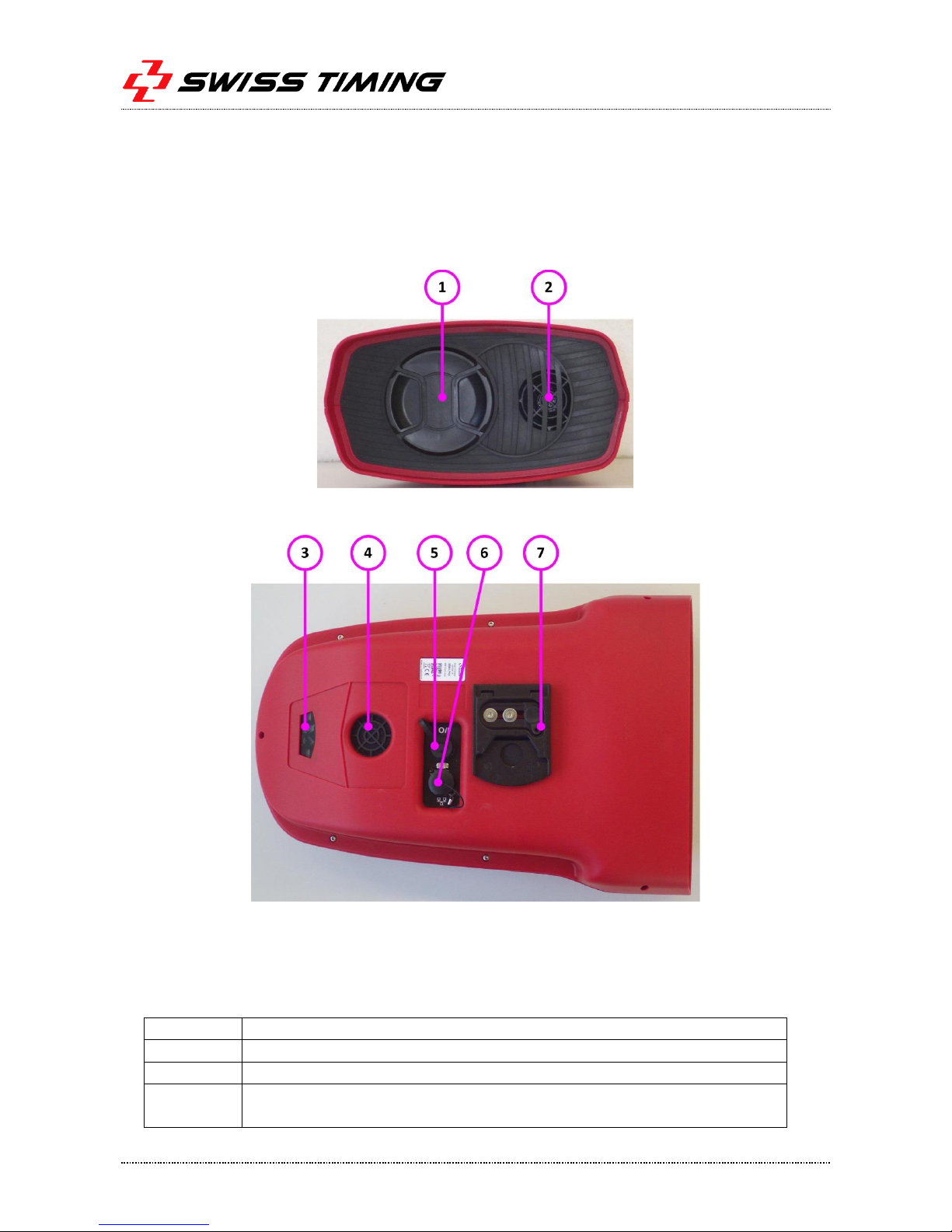
1.1 MYRIA parts
1. Lens protective cap (lens is behind)
2. Air output (with internal filter)
3. Status LEDs
4. Air input (with internal filter)
5. I/O connector
6. Ethernet connector
7. Fixation plate
Figure 1 – MYRIA 10/16 front view
Figure 2 – MYRIA bottom view
1.2 Definitions
The camera is typically supplied with a support permitting the setting of its position according to 4
axes, here are the definitions used in this manual:
Translation
Horizontal displacement, perpendicular to the finish line.
Pan
Rotation in the horizontal plane.
Tilt
Rotation in the vertical plane, in the axis of the finish line.
Swivel
Rotation in the vertical plane, perpendicular to the finish line (to have the
sensor "vertical" in the plane of the finish line).
 Loading...