

Page 1

Users
Manual
Page 2
Users
Manual
Swissonic AG
P.O. Box 304
CH-8730 Uznach
Switzerland
Phone +41552858610
Fax +415528586 15
www.swissonic.com
[email protected]
Swissonic America
407 Stony Point RD
Santa Rosa
CA 95401
Phone 707 577 7691
Fax 707 577 7692
www.swissonic.com
infousa
@
swissonic.com
Statement of conformity
To whom it may concern
This letter is our statement of conformity to the appropriate CE certifications. Based on testing performed in
September 1999, our products, Swissonic AD96 and
Swissonic DA96 meet all pertinent worldwide
regulations, including CE. This certification is based on
test reports generated by EMC-Testcenter Zürich AG,
Zurich, Switzerland. Copies of the reports are available
upon request.
Uznach, December 1, 1999
Daniel Feusi
General Manager Swissonic AG
Page 3

Make sure that the value written on the unit’s voltage
selector (near the power entry jack) matches your line
voltage. Connect the unit to mains and to the USB
port on your computer. Turn on the unit. After a few
seconds, the operating system should detect the unit
and show it in the device list (It may ask for the system
CD first). USB Studio runs with the drivers provided
by the operating system (Windows 98 or 2000 or Mac
System 9).
Check that all pots are turned all the way left, and the
pushbutton switches on the front panel are disengaged.
Connect your monitoring system input to the «Mon
out» RCA jacks on the back (alternatively, use the
headphone output on the front). Play some sound over
the audio device in your computer. Turn the «Computer»
pot all the way up, then adjust the monitoring level
using the «Monitor» and/or «Headphone» pot.
Connect a signal source to one of the unit’s analog
inputs on the back. Turn the input’s level pot up making
sure the «MON OL» Led is off, or just very briefly
lights during loud transients. You should hear the
source through the monitors. Push the «REC EN»
switch of the respective input, then bring the «Rec
Level» pot up. Watch the level on the Led bar. Now, you
should be able to record the signal in your computer.
To hook up a digital source to the USB Studio D, plug
it in the TOSLINK or RCA connector on the back.
Make sure the input selection switch on the rear is in
the right position (Opto or Coax). The LOCK led on
the front panel should light. By turning up the «Digital
In» pot, you should be able to hear the signal in the
monitors, or, when the REC EN switch is pushed in,
record it over the USB interface. The digital out takes
the signal from either the REC or the MON mixes, as
set by the switch on the front panel. Make sure the
level is low enough not to light the OL Led.
Designed for recording studio quality sound, the USB
Studio combines the flexibility of an 11-channel stereo
mixer with the ease of use of the USB interface. Two
professional quality mic pres allow the connection of
(and do justice to) any mic. High impedace instrument
inputs, a phono preamp and four stereo inputs complete
the device. The USB Studio D adds support for optical
and coax S/PDIF digital i/os. True 20-bit converters
and matching signal processing circuits place the USB
Studio in a class of it’s own.
Quick Start
Overview
4
Page 4

n
11-channel, 2-bus stereo mixer
n
Two professional quality microphone
preamplifiers with 48V phantom power
and phase inversion switches
n
Insert jacks allow the use of external
compressors or effect units
n
Two high impedance instrument preamplifiers
n
Combined level/gain pots on mic and instrument
inputs simplify setup while maximising SNR
n
High quality RIAA phono preamplifier
n
Four stereo line inputs
n
20-bit AD/16-bit DA conversion
to/from USB interface
n
20-bit AD/DA conversion to/from S/PDIF
input/output
n
8-Led peak level meters for recording level
n
Can do sample rate conversion between the digital
I/Os and the USB interface
n
Level controlled monitor output
n
High quality headphone output
n
1HU rugged all steel case with internal power supply
5
Page 5
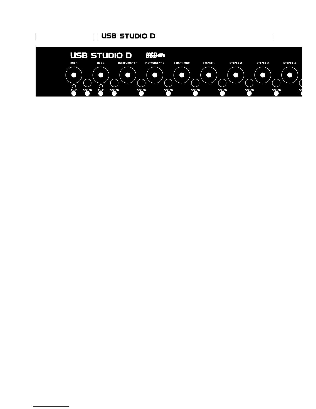
1 Mic 1/2 level pots. Adjust the level of the
respective Mic input. The preamp gain is
automatically adjusted as well, to optimise
SNR and distortion. When turned all the way to the
left, the channel is turned off completely.
2 Mic 1/2 phantom power Leds. When lighted,
show that 48V phantom power is switched on
for the respective input. Some mics could be
damaged by phantom power, so make sure it’s
turned off before connecting one of those.
3 Mic 1/2 record enable switches. When switched
off, the respective input is routed to the monitor
bus. When on (in) the input is added to the rec
bus. When monitoring, both Mic inputs are panned
in the center. When recording, Mic 1 goes to the
left channel and Mic 2 to the right.
4 Instrument 1/2 level pots. As for the Mic inputs,
these also change the preamp gain,
and can turn the channel completely off.
5 Instrument 1/2 record enable switches. When
switched off, the respective input is routed to
the monitor bus. When on (in) the input is added
to the rec bus. When monitoring, both instrument
inputs are panned in the center. When recording,
Instrument 1 goes to the left channel and
Instrument 2 to the right.
6 Line/phono, stereo inputs, digital in level pots.
These are stereo pots adjusting the level of the
respective inpus.
7 Line/phono, stereo inputs, digital in record
enable switches. When switched off, the
respective input is routed to the monitor bus.
When on (in) the input is added to the rec bus.
8 Digital in lock led. When lighted, this shows that
a valid source has been connected to the digital
input, and that the unit has locked to that.
9 Computer level pot. This pot adjusts the level
of the signal coming through the USB interface.
It is always routed to the monitor bus.
Front Panel
6
1
2 3
4
5
6
7
1
2 3
4
5
6
7
6
7
6
7
6
7
Page 6
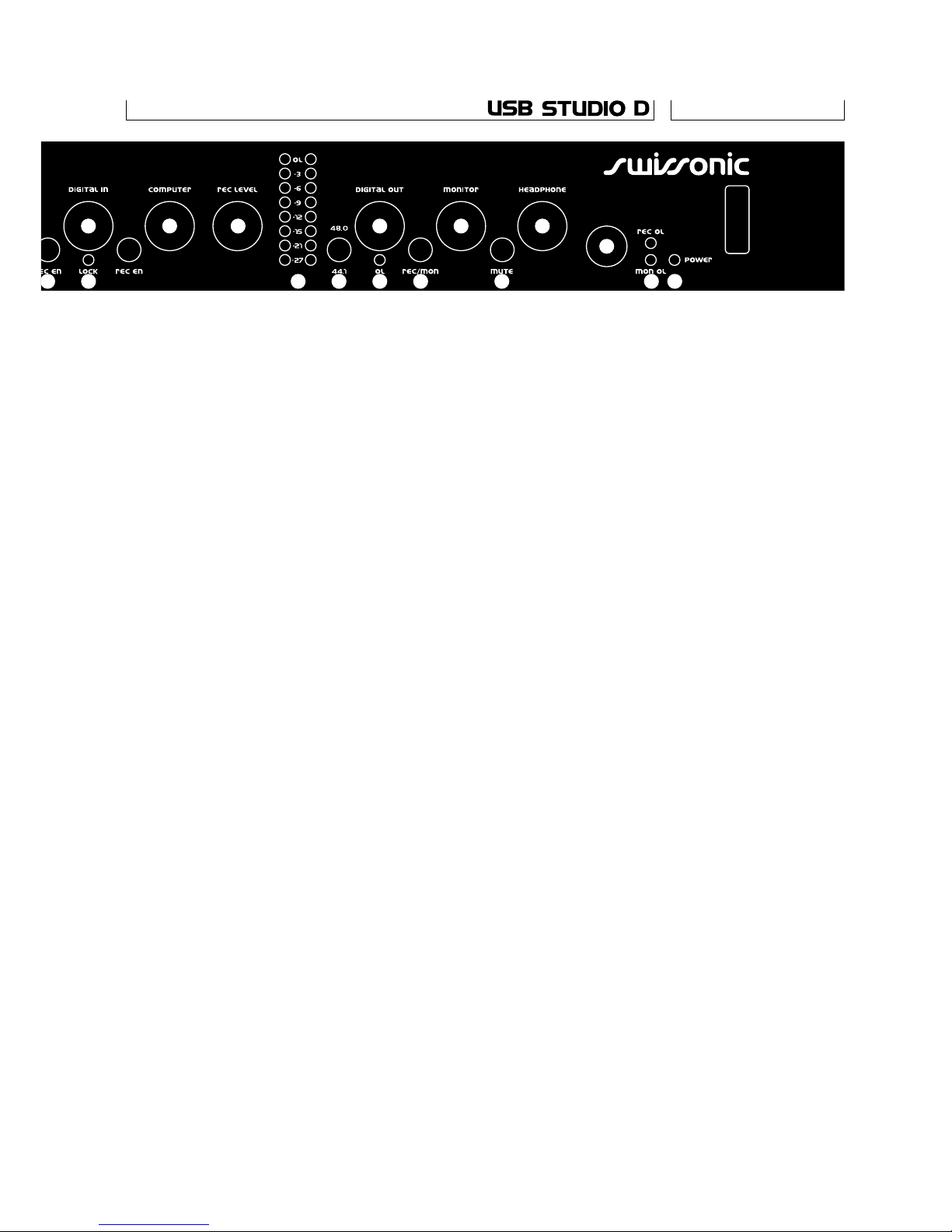
10 Record level pot. Adjusts the level of the signal
going to the computer via the USB bus interface.
The actual level is shown on the led bar next.
11 Recording level led bar. A peak level meter of the
signal that is recorded through the USB interface.
The red Led is only 1dB below clipping,
so it should never light, or distortion will occur.
12 Digital out level. Adjusts the level of the
signal going to the digital out interface.
13 Sample rate selector for digital output. Selects
the sample rate of the digital output when the
unit is not locked to a S/PDIF source. When
the unit is locked to a S/PDIF source, the digital
output will run at the same rate as the input.
14 Digital out overload Led. This Led lights when
the peak level at the digital output is less that
6 dB below clipping. So, it should only be allowed
to light briefly during the loudest transients.
15 Digital out source switch. This switch sets
whether the digital output is taken from the
record (switch out) or the monitor bus (switch in).
16 Monitor level pot. Adjusts the level of the
signal at the monitor output jacks on the back.
17 Monitor mute switch. Mutes the monitor
output when pressed in.
18 Headphone level pot. Adjusts the level
at the headphone output next.
19 Headphone jack. The headphone signal is taken
from the monitor bus. The output is capable of
pretty high levels, so be careful.
20 Record and monitor bus overload leds. These
Leds show when the level of the respective
busses is dangerously close to clipping (less
than 6dB headroom). If these light, one of the
inputs’ level pots should be turned down.
21 Power switch and Led.
7
8 11
9
10 12
13 14 15
16
17
18
19
20 217
6
Page 7
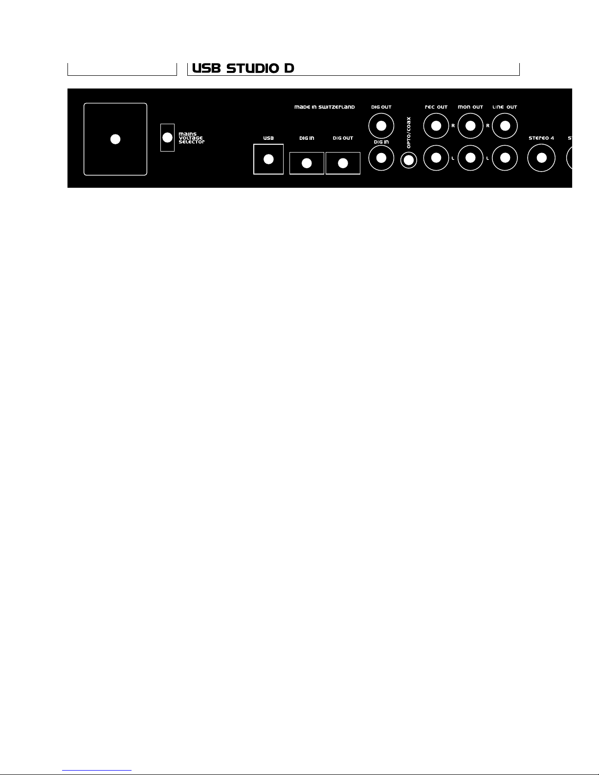
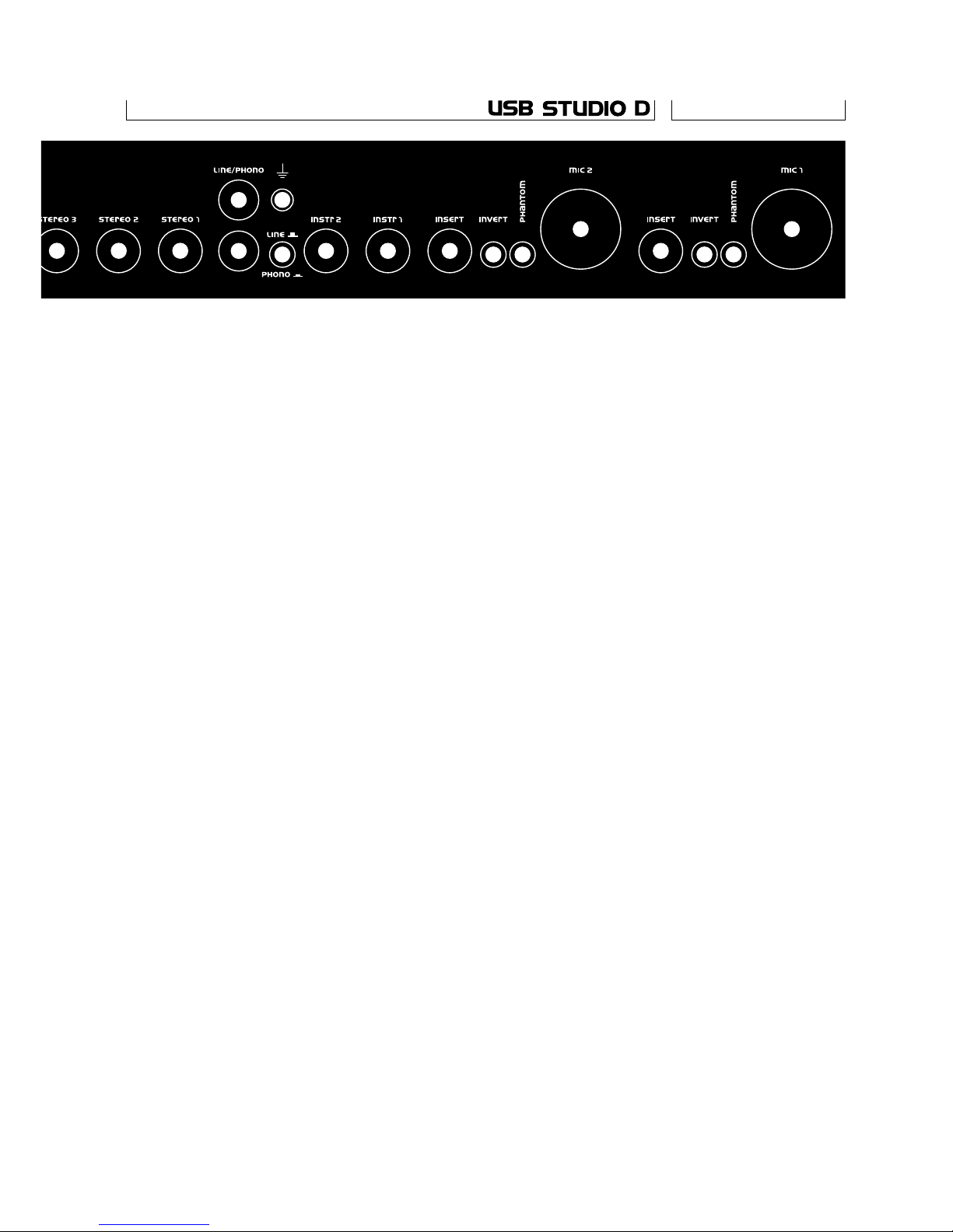
Rear Panel 1 Mic 1/2 input jacks. Balanced XLR Mic inputs.
1=ground, 2= plus, 3=minus.
2 Mic 1/2 phantom power switches. When pushed
in, enable 48V phantom power on the Mic inputs,
and light the corresponding front panel leds.
3 Mic 1/2 invert switches. Invert the polarity
of the corresponding input when pushed in.
Useful for solving phasing problems.
4 Mic 1/2 insert jacks. Used for effect loops
before mixing. The insert jacks are wired with
tip=send, ring =return. The send signal is taken
after the level pot.
5 Instrument 1/2 input jacks. These are high
impedance mono (TS) inputs.
6 Turntable grounding terminal. A 4 mm banana jack
used to connect the chassis/shield of the turntable.
7 Phono/line selection switch. When released, the
phono/line input is configured as a RIAA
phono preamp. When pushed in,
it is a normal unbalanced line input.
8 Phono/line input jacks. L/R RCA inputs for phono/line.
9 Stereo jack inputs. Four 6,3mm stereo TRS
unbalanced line inputs.
10 Line output jacks. The signal on the monitor bus
before the monitor level pot is presented over
these RCA jacks.
8
11 1012
13
14
15
16
17
18
15
9
11 1012
14
Page 8
11 Monitor output jacks. Used to feed the monitor
amp. The signal here is taken from the monitor
bus, after the monitor level pot and mute switch.
12 Rec output jacks. The recording bus signal before
the rec level pot is presented here.
13 Opto/coax switch. Select whether the digital
in signal is taken from the coax or opto input.
14 Digital in/out RCA jacks. These are the 75 Ω
coax digital i/os.
15 Digital in/out TOSLINK jacks. These are the
optical connectors for digital i/o. Keep them
covered when not in use.
16 USB connector. The USB cable to the
computer plugs in here.
17 Voltage selector switch. Make sure you check
the voltage selector switch setting before
plugging the unit in, or damage can occur.
18 Power connector. The mains cable is inserted
here. Also contains an integral fuse holder.
For protection against fire hazard and unit
damage, make sure you the correct type and
rating of fuse is used for your mains voltage.
9
1
23
4
5
6
8
7
9
1
23
45
99
8
Page 9

USB Studio uses one of the finest ultra-low noise
amplifier designs available. Its gain range allows the
use of virtually any type of microphone. True 48V
phantom power guarantees the USB Studio works
with every microphone made. The phantom power
supply can be turned on and off for each input via a
back panel switch. A Led on the front panel is lighted
when it’s turned on.
The level control used is combined with a gain trim.
Unlike a normal trim, it can be turned completely off.
Full input dynamic range is retained in the circuit.
An invert switch is provided on the back panel to solve
phasing problems when two mics are used in close
proximity. If the sound seems weak or thin (especially
a noticeable loss of bass) when both Mic or Mic and
instrument inputs are used, try using one of the invert
pushbuttons. This problem occurs when the same
sound reaches two inputs out of phase because of
their placement or wiring, and the outputs are canceling instead of combining.
USB Studio allows an external signal processor, such
as a compressor or effect unit to be inserted between
the output of the Mic channels and the mixer. A standard
TRS insert style (tip=send, ring =return) Y-cord gets
input and output from the Insert jack to the effects
unit. The «send» signal is taken after the level pot. The
return signal is added to the mix with fixed 0dB gain.
The instrument inputs of the USB Studio are very high
impedance, high gain range, low noise, unbalanced
inputs suitable for piezo or magnetic instrument pickups.
Unablanced microphone pickups can also be connected
here. As with the Mic inputs, the level controls are
combined with gain trims.
The phono preamplifier used in the USB studio is
suitable for use with moving magnet pickups. It has
the standard 50kΩ input impedace, and is provided
with jumpers (JP17 and JP19) that increase the input
capacitance from the nominal 40pF to 250pF, in order
to optimise pickup matching. The circuit provides
accurate RIAA equalisation. If the turntable is provided
with an earthing connection, make sure it is tied with
a thick wire to the grounding socket near the phono
inputs. A switch on the back panel disables the phono
preamp feature, enabling the input to be used as
a normal stereo input.
Microphone
Inputs
Insert Loops
Instrument
Inputs
Phono/Line
Input
10
Page 10

The USB Studio incorporates the function of a 2-bus
stereo mixer. The two buses are called «rec» and
«mon». As its name implies, the «rec» bus is normally
used for recording, and the «mon» for monitoring. The
signal on the two buses is provided in analog format
on the back, on the «rec» and «line» output jacks.
Each input to the mixer has an «assign» switch,
labeled Rec/Mon on the front panel. When the switch
is in its «out» position, the input is assigned to the
mon bus; when it’s pressed in, it goes to the rec bus,
and is disconnected from the mon bus.
The signal from the rec bus is taken through the Rec
Level control and sent over the USB interface to the
computer. The level of the signal sent is displayed on
the led bar level meter.
The signal path from any input to any output of the
USB Studio passes through two level controls: one at
the input, and one at the output. So, the same overall
gain can be obtained with different settings of the two
controls. Selection of the best combination is what
gain staging is all about. In order to optimize signal
to noise ratio, the input gain should be as high as posible, but low enough so the internal circuits don’t overload and distort the signal. To aid in this setting, two
overload indicators are provided, one for each bus.
The input gain should be set so that with the loudest
input, the overload led lights briefly during transients.
This will ensure the signal is within 5dB of clipping.
Then, for extra headroom, the input level should be
backed a little, especially if the input comes from an
unpredictable source. Once all inputs are thus adjusted, the output can be set to the desired level.
The signal from all the inputs that are not assigned to
the rec bus and the playback (output) channel of the
USB interface are added together on the monitor bus.
From here, it can be output to the external monitor
amp via the monitor level control and mute switch, or
to the headphone output.
In normal operation, the sources assigned to the rec
bus are played back by the computer after processing,
and can be thus monitored during recording. However,
some applications run so slowly, that the delay
through the computer make such monitoring difficult,
if not impossible. For these situations, USB studio is
provided with a jumper option to enable the inputs to
remain connected to the mon bus even while recording.
Mixer operation
Gain staging
Monitoring
11
Page 11

To enable this feature, move the two jumpers near
each assign switch to their «on» position. They are:
JP3 and JP4 for Mic1; JP7 and JP8 for Mic2; JP5 and
JP6 for Instrument 1; JP9 and JP10 for Instrument 2;
JP21 and JP22 for Phono; JP1 and JP2 for Stereo 1;
JP11 and JP12 for Stereo 2; JP13 and JP14 for
Stereo 3; JP15 and JP16 for Stereo 4; JP18 and
JP20 for Digital in.
USB Studio D’s digital input and output are completely
separated from the USB interface. They use very high
performance, 20-bit AD and DA converters, and
support both the optical and coaxial S/PDIF formats.
The digital input is treated like another input to the
mixer, with its own level control and assign switch. A
lock Led on the front panel shows when the unit has
locked to the incoming signal and the input is enabled.
A switch on the back selects between the coaxial and
optical input. If the lock led does not light after signal
is applied, there’s a good chance the opto/coax
switch is in the wrong position.
The digital output can be taken from either the rec or
the mon bus, as selected by the switch on the front.
An overload led lights when the signal to the digital out
is near clipping, and needs to be reduced. Both the
coaxial and optical outputs are driven simultaneously.
The sample clock of the digital input and output is
independent from that of the USB interface. This way,
the unit can perform high quality sample rate conversion
between the USB and the S/PDIF channels.
The digital input and output always run at exactly the
same sample rate. So, when the digital input is locked,
the digital output uses the sample clock recovered
from the input. When there is no input present, an
internal clock generator drives the digital output. The
sample rate of the internal generator is selected with
the 44,1/48 switch on the front panel.
The USB interface implements two digital stereo
channels over an USB bus: one channel towards the
computer – the recording channel, and one from the
computer – the playback channel.
The USB interface conforms to the generic audio
device standard as defined in the USB specification,
and as such, it doesn’t need a special driver; all it’s
functions are controlled by the generic driver provided
with the operating system.
When USB Studio is first plugged into the USB
12
Digital Input
and Output
USB Interface
Page 12

interface of the computer, it should automatically be
recognised, and drivers for it installed in the system.
Usually, this requires the operating system CD.
After the drivers are installed, the USB recording and
playback peripherals should be listed in the audio
device list.
To hear signal played though the playback device, turn
the Computer and Monitor level controls up. Also,
make sure the digital level control in the computer
is up. To record something, apply the signal to one
of the USB Studio’s inputs, turn its level up, press
the rec/mon switch, turn the Record level control
up and record. The signal presence should be seen on
the led bar.
If the computer doesn’t recognise the unit properly,
first make sure the connections are secure, and that
the operating system supports the USB audio devices
(Windows 98, 2000 and Mac System 9 do). Then,
with both the computer and the USB Studio on,
disconnect the USB cable at one end, wait a few
seconds and plug it back in. Changing the USB topology
(e.g. plugging the unit directly in an USB port on the
computer rather that in an external hub) may help is
some cases.
The drivers sometimes default to a low sample rate
(like 22,05 kHz). Although USB Studio supports the
lower sample rates, the loss in sound quality is important. We recommend that you use only 44,1 or 48kHz.
13
Page 13

Specifications Microphone Inputs
Input impedance 1kΩ, Balanced
Gain range Off to >+50 dB
Phantom power +48±4% VDC, IEC268-15
Max. input level –5/–35dBu,
+20/+50 dB Gain
Equivalent input noise –125dBu, 20k BW, 50dB
gain, Rs=150 Ω
Frequency response 20–20000 Hz@–0,1 dB,
all gains
THD+ Noise 0,005%, Gain = 20dB
0,01%, Gain = 50dB
Instrument Inputs
Input impedance 20MΩ || 60pF
Gain range Off to >+50dB
Max input level –5/–35dBu, +20/+50dB in
Equivalent input noise –110dBu, 20k BW, 50dB
gain, Rs=600 Ω
THD+Noise 0,02%, 20k BW, 50dB
gain, Rs=600 Ω
Frequency response 15–40000Hz@ –3dB
Phono Input
Input impedance 50kΩ
RIAA correction error <1dB, 20–20000Hz
Gain 34dB@ 1kHz
THD+Noise 0,02%@ 1kHz, 20k BW
Line Inputs
Input impedance 50 kΩ
Gain range Off to 0dB
Clipping level >+20dBu
Line Outputs
Output impedance 100Ω
Clipping level >+20dBu
Any one line input
to any line output
THD+Noise 0,003%,
Level=max, rl =600Ω
SNR 100dB, Ref= +10dBu
Frequency response 20–20000Hz@ –0,1dB
14
Page 14

Headphone Output
Output impedance 47Ω
Clipping level >+20dBu
THD+Noise 0,01%, 1kHz, 20k BW,
+10dBu, rl= 50Ω
Gain from monitor bus Off to 0dB
Digital I/O
Format S/P DIF
Interface Coax or TOSLINK optical
Resolution 20bits
Sampling rates 32/44,1/48 ±4%kHz
External clock
44,1/48 ±100ppm kHz
Automatically selected
Digital Output ADC
SNR and Dynamic Range 98dB, A-weighted
(20–20000 Hz) 95dB, unweighted
Total Harmonic
Distortion + Noise –90dB, input lev.=–1 dBFS
Total Harmonic Distortion 0,003%
input level=–1 dBFS
Interchannel
Phase Deviation 1deg, 20–20000 Hz
Interchannel Gain Matching 0,1 dB, 20–20000 Hz
Passband 20–0,45@sample
frequency kHz@–0,1 dB
Passband ripple < 0,01dB
Interchannel Isolation 90dB@ 1kHz
Digital Input DAC
SNR and Dynamic Range 98dB, A-weighted
(20–20000 Hz) 95dB, unweighted
Total Harmonic
Distortion + Noise –88dB
output level=0 dBFS
Total Harmonic Distortion 0,003%
output level=0 dBFS
Interchannel
Phase Deviation 1deg, 20–20000Hz
Interchannel Gain Matching 0,1 dB, 20–20000Hz
Passband 20–0,45@sample
frequency kHz@–0,1 dB
Passband ripple <0,01dB
Interchannel Isolation 90dB@ 1kHz
15
Page 15

USB Port
Format Standard USB audio device
Sampling rates 8/11,025/12/16/22,05/
24/32/44,1/48kHz
USB ADC
Resolution 20bits
SNR and Dynamic Range 95dB, A-weighted
(20–20000 Hz) 90dB, unweighted
Total Harmonic Distortion 0,01%
input level=–1 dBFS
Interchannel
Phase Deviation 1deg, 20–20000 Hz
Interchannel Gain Matching 0,1 dB, 20–20000 Hz
Passband 20–0,45@sample
frequencykHz@ –0,1dB
Passband ripple <0,1 dB
Interchannel Isolation 90dB@ 1kHz
USB DAC
SNR and Dynamic Range 92dB, A-weighted
(20–20000 Hz) 89dB, unweighted
Total Harmonic
Distortion+Noise –85dB
output level=0 dBFS
Total Harmonic Distortion 0,005%
output level=0 dBFS
Interchannel
Phase Deviation 1deg,20–20000 Hz
Interchannel Gain Matching 0,1 dB, 20–20000Hz
Passband 20–0,45@sample
frequencykHz@ –0,1dB
Power Supply Requirements
Input Voltage 100–120;
220–240, VAC ±6 %
Power consumption <30W
Fuse Ratings 0,16 AT (220–240V)
0,315 AT (100–120V)
Other
Unit Size 4,4@48,3@15 cm
Unit Weight 3 kg
Operating
Temperature Range 0–40ºC
Operating Humidity 0–90%, non-condensing
16
Page 16

Notes
17
Page 17

Notes
18
Page 18

Swissonic AG warrant this equipment against defects
in materials and workmanship for a period of twelve
months from the date of original retail purchase. If you
discover a defect, first write or call Swissonic AG at
(0041) 55 285 86 10 to obtain a Return Merchandise
Authorization Number. No service will be performed
on any product returned without prior authorization.
Swissonic AG will, at its option, repair or replace the
product at no charge to you, provided you return it
during the warranty period, with transportation
charges prepaid, to Swissonic AG, P.O. Box 304,
CH-8730 Uznach, Switzerland. You must use the
product’s original packing material for in shipment, and
insure the shipment for the value of the product.
Please include your name, address, telephone
number, a description of the problem, and the original,
dated bill of sale with the returned unit and print
the Return Merchandise Authorization Number on
the outside of the below the shipping address. This
warranty does not apply if the equipment has been
damaged by accident, abuse, misuse, or misapplication;
has been modified without the written permission of
Swissonic AG, or if the product serial number has
been removed or defaced. All implied warranties,
including implied warranties of merchantability and
fitness for a particular purpose, are limited in duration
to one year from the date of the original retail
purchase of this product. The warranty and remedies
set forth above are exclusive and in lieu of all others,
oral or written, express or implied. No Swissonic
distributor, dealer, agent, or employee is authorized
to make any modification, extension, or addition
to this warranty. Swissonic AG is not responsible for
special, incidental, or consequential damages resulting
from any breach of warranty, or under any legal theory,
including lost profits, downtime, goodwill, damage
or replacement of equipment and property and
cost of recovering reprogramming, or reproducing any
program or data stored in or used with Swissonic
products. Some states do not allow the exclusion or
limitation of implied warranties or liability for
incidental or consequential damages, so the above
limitation or exclusion may not apply to you. This
warranty gives you specific legal rights, and you may
have other rights which vary from state to state.
Uznach, Switzerland, December 1, 1999
This equipment has been
tested and found to
comply with the limits for
a class B digital device,
pursuant to part 15 of the
FCC rules. These limits
are designed to provide
reasonable protection
against harmful interference in a residental installation. This equipment
generates, ises, and can
radiate radio frequency
emergency and, if not installed and used in accordance with the instruction manual, may cause
harmful interference to
radio communications.
However, there is no
guarantee that interference will not occur
in a particular installation.
If this equipment does
cause interference to
radio or television equipment reception, which
can be turning the equipment off and on, the user
is encouraged to correct
the interference by any
combination of the following measures:
n
Relocate or reorient
the receiving antenna
n
Increase the separation
between the equipment
and the receiver
n
Plug the equipment into
an outlet on a circuit
different from that to
which the receiver is
connected
If necessary, you can
consult a dealer or experienced radio/television
technician for additional
assistance.
PLEASE NOTE: only
equipment certified to
comply with Class B
(computer input/output
devices, terminals, printers etc) should be
attached to this equipment, and it must have
sheilded interface cables
in order to comply with
the Class B FCC limits
on RF emissions.
WARNING: changes or
modifications to this unit
not expressly approved
by the party responsible
for compliance could
voide the user’s authority
to operate the equipment.
19
Limited Warranty on Hardware
Page 19

Swissonic AG
P.O. Box 304, CH-8730 Uznach, Switzerland
Phone +41552858610, Fax +41552858615
www.swissonic.com, info
@
swissonic.com
Swissonic America
407 Stony Point RD, Santa Rosa, CA 95401
Phone 707 577 7691, Fax 707 577 7692
www.swissonic.com, infousa
@
swissonic.com
 Loading...