

Page 1

ControlKey 49, ControlKey 61, ControlKey 88
MIDI keyboard
user manual
Page 2

Musikhaus Thomann
Thomann GmbH
Hans-Thomann-Straße 1
96138 Burgebrach
Germany
Telephone: +49 (0) 9546 9223-0
E-mail: info@thomann.de
Internet: www.thomann.de
10.12.2015, ID: 337456, 337460, 337462
Page 3

Table of contents
1 General information.............................................................................................................. 4
1.1 Further information........................................................................................................ 4
1.2 Notational conventions................................................................................................. 4
1.3 Symbols and signal words........................................................................................... 5
2 Safety instructions................................................................................................................. 6
3 Features....................................................................................................................................... 7
4 Installation and starting up............................................................................................... 8
5 Connections and operating elements.......................................................................... 9
6 Functions.................................................................................................................................. 14
7 MIDI routing............................................................................................................................ 19
8 Factory defaults.................................................................................................................... 23
9 Other presets.......................................................................................................................... 25
10 Note values.............................................................................................................................. 26
11 Technical specifications.................................................................................................... 27
12 Troubleshooting................................................................................................................... 28
13 Protecting the environment........................................................................................... 29
Table of contents
ControlKey 49, ControlKey 61, ControlKey 88
3
Page 4

1 General information
This manual contains important instructions for the safe operation of the unit. Read
and follow the safety instructions and all other instructions. Keep the manual for
future reference. Make sure that it is available to all those using the device. If you sell
the unit please make sure that the buyer also receives this manual.
Our products are subject to a process of continuous development. Thus, they are
subject to change.
1.1 Further information
On our website (www.thomann.de) you will find lots of further information and
details on the following points:
Download This manual is also available as PDF file for you to download.
Keyword search
Use the search function in the electronic version to find the
topics of interest for you quickly.
Online guides
Our online guides provide detailed information on technical
basics and terms.
Personal consultation
For personal consultation please contact our
technical hotline.
Service
If you have any problems with the device the
customer service will gladly assist you.
1.2 Notational conventions
This manual uses the following notational conventions:
The letterings for connectors and controls are marked by square brackets and italics.
Examples: [VOLUME] control, [Mono] button.
Texts and values displayed on the device are marked by quotation marks and italics.
Examples: ‘24ch’, ‘OFF’.
Letterings
Displays
General information
MIDI keyboard
4
Page 5

The individual steps of an instruction are numbered consecutively. The result of a
step is indented and highlighted by an arrow.
Example:
1. Switch on the device.
2. Press [Auto].
ð
Automatic operation is started.
3. Switch off the device.
References to other locations in this manual are identified by an arrow and the speci‐
fied page number. In the electronic version of the manual, you can click the crossreference to jump to the specified location.
Example: See Ä ‘Cross-references’ on page 5.
1.3 Symbols and signal words
In this section you will find an overview of the meaning of symbols and signal words
that are used in this manual.
Signal word Meaning
DANGER! This combination of symbol and signal word indicates
an immediate dangerous situation that will result in
death or serious injury if it is not avoided.
NOTICE! This combination of symbol and signal word indicates
a possible dangerous situation that can result in mate‐
rial and environmental damage if it is not avoided.
Warning signs Type of danger
Warning – danger zone.
Instructions
Cross-references
General information
ControlKey 49, ControlKey 61, ControlKey 88
5
Page 6

2 Safety instructions
This device is intended to be used to control electronic tone generators. Use the
device only as described in this user manual. Any other use or use under other oper‐
ating conditions is considered to be improper and may result in personal injury or
property damage. No liability will be assumed for damages resulting from improper
use.
This device may be used only by persons with sufficient physical, sensorial, and intel‐
lectual abilities and having corresponding knowledge and experience. Other persons
may use this device only if they are supervised or instructed by a person who is
responsible for their safety.
DANGER!
Danger for children
Ensure that plastic bags, packaging, etc. are disposed of properly and
are not within reach of babies and young children. Choking hazard!
Ensure that children do not detach any small parts (e.g. knobs or the
like) from the unit. They could swallow the pieces and choke!
Never let children unattended use electrical devices.
NOTICE!
Operating conditions
This device has been designed for indoor use only. To prevent damage,
never expose the device to any liquid or moisture. Avoid direct sunlight,
heavy dirt, and strong vibrations.
NOTICE!
External power supply
The device is powered by an external power supply. Before connecting
the external power supply, ensure that the input voltage (AC outlet)
matches the voltage rating of the device and that the AC outlet is pro‐
tected by a residual current circuit breaker. Failure to do so could result
in damage to the device and possibly the user.
Unplug the external power supply before electrical storms occur and
when the device is unused for long periods of time to reduce the risk of
electric shock or fire.
Intended use
Safety
Safety instructions
MIDI keyboard
6
Page 7

3 Features
n MIDI keyboard and controller
n semi-weighted velocity-sensitive keys with Aftertouch
n Pitch bend and modulation wheel
n velocity-sensitive trigger pads
n eight rotary encoders
n eight mute and solo buttons
n nine faders
n Menu and transport buttons
n Octave / transpose function
n 30 memory locations for scenes
n backlit LCD
n Connectors for Sustain and Expression pedal
n 5-pin MIDI output, USB output
n MAC and Windows compatible
n Power supply via 9 V mains adapter or USB cable
Features
ControlKey 49, ControlKey 61, ControlKey 88
7
Page 8

4 Installation and starting up
Unpack and carefully check that there is no transportation damage before using the
unit. Keep the equipment packaging. To fully protect the device against vibration,
dust and moisture during transportation or storage use the original packaging or
your own packaging material suitable for transport or storage, respectively.
Establish all connections as long as the unit is switched off. Use the shortest possible
high-quality cables for all connections.
Power supply is enabled once you connect the unit through the USB port and the
included USB cable to a PC. If desired, connect a Sustain and / or an Expression pedal
to the device (pedals are not included). Turn on the device using the main switch on
the rear panel.
Start the DAW installed on your computer and adjust the software and MIDI settings.
System requirements
n Windows XP/Vista/7®, mind. 800 MHz, 256 MB RAM min.
n Mac OS X V.10.4.9® and higher, mind. 733 MHz, mind. 512 MB RAM
To operate the device with any MIDI device (such as a sound module) you need an
external 9V mains adapter for power supply (not included). In this case, connect your
device via the 5-pin MIDI output on the rear panel to the input of the MIDI device. If
desired, connect a Sustain and / or an Expression pedal to the device (pedals are not
included). Turn on the device using the main switch on the rear panel.
Operation with a computer
Operation with a MIDI device
Installation and starting up
MIDI keyboard
8
Page 9

5 Connections and operating elements
Model overview
Connections and operating elements
ControlKey 49, ControlKey 61, ControlKey 88
9
Page 10

1 [PITCHBEND]
Pitch bend wheel to vary the pitch when playing.
2 [MODULATION]
Modulation wheel.
3 [OCTAVE]
Buttons to octave / transpose the keyboard.
4 Display.
5
Function / select buttons, see Ä ‘Function / select buttons [5]’ on page 11.
6 [E1] … [E8]
Rotary encoder
7 [S1] … [S8]
Fader with LED chain display.
8 [A1 | B1] … [A8 | B8]
Mute / solo buttons.
9 [TRACK]
Button for the simultaneous shifting of all encoders and faders.
10 [MASTER]
Master fader.
11 [P1] … [P8] ([P16])
Programmable trigger pads.
Top view
Connections and operating elements
MIDI keyboard
10
Page 11

12
Function / select buttons, see Ä ‘Function / select buttons [12]’ on page 12.
13 Transport buttons:
back, forward, stop, play, record
14 [SCENE]
Button to activate the Scene mode.
15 [MENU]
Button to activate the Edit mode.
16
[PAGE]
Buttons to navigate between the parameters and functions available (all modes).
17
[PATCH]
Buttons to send programme change commands.
18
[VALUE]
Buttons to adjust / select values / options in Edit and Scene mode.
19
[CHANNEL]
Buttons to switch between the available channels.
20 [EXIT]
Button to exit the open menu or menu function.
21 [ENTER]
Button to confirm parameter changes.
Function / select buttons [5]
Connections and operating elements
ControlKey 49, ControlKey 61, ControlKey 88
11
Page 12
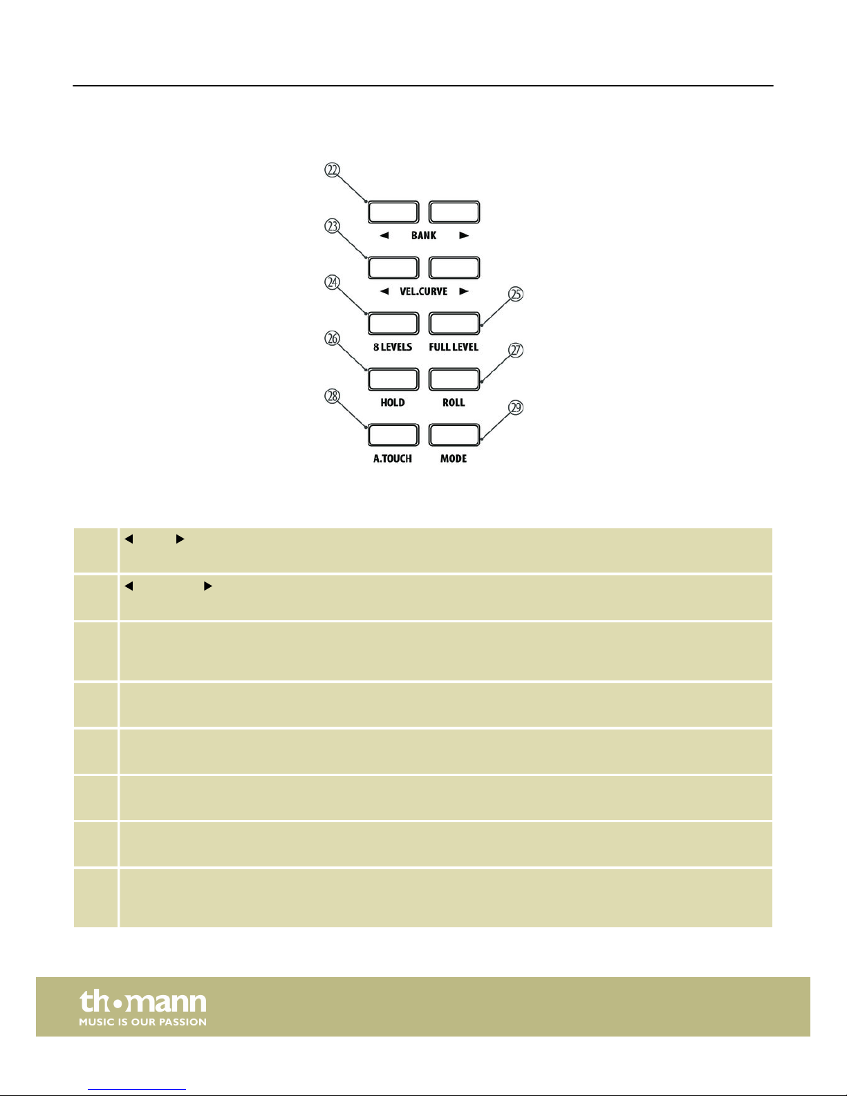
22
[BANK]
Buttons to switch between the preset banks and trigger pads.
23
[VEL.CURVE]
Buttons to adjust the touch sensitivity of all trigger pads.
24 [8 LEVELS]
Button to quickly toggle the touch sensitivity of all trigger pads to a fixed value. The button lights up when the mode is
active.
25 [FULL LEVEL]
Button to quickly toggle all trigger pads to maximum touch sensitivity. The button lights up when the mode is active.
26 [HOLD]
Button to activate the Hold mode of the trigger pads. The button lights up when the mode is active.
27 [ROLL]
Button to activate the Roll mode of the trigger pads. The button lights up when the mode is active.
28 [A.TOUCH]
Button to disable the Aftertouch function of the trigger pads. The button lights up when the function is deactivated.
29 [MODE]
Button to toggle between the transmission modes of the trigger pads (note or controller commands). The button lights
up in ‘Controller commands’ mode.
Function / select buttons [12]
Connections and operating elements
MIDI keyboard
12
Page 13
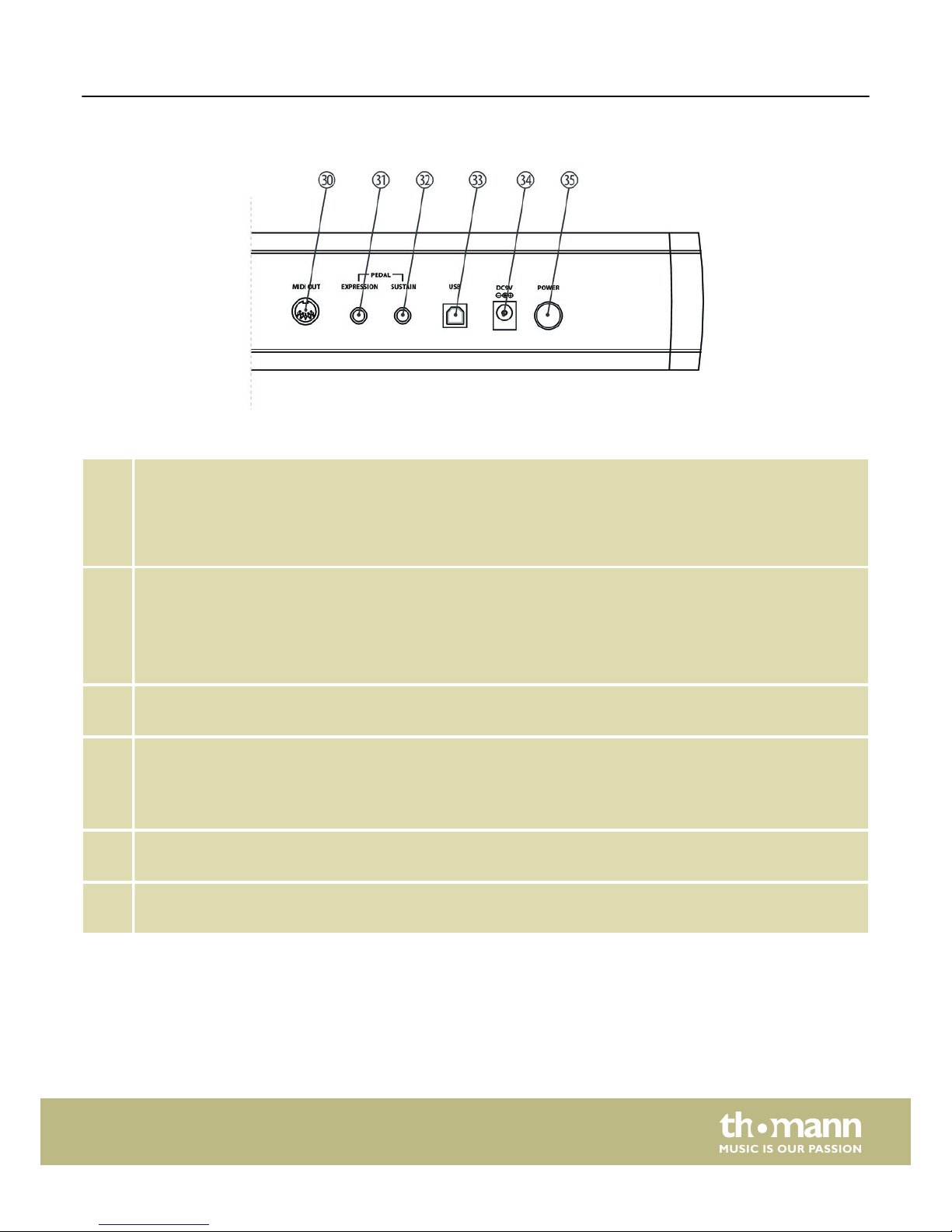
30 [MIDI OUT]
Use a MIDI cable to connect the 5-pin MIDI port on the rear panel of the MIDI keyboard to the MIDI input of a sound
module.
At MIDI connections, the device that controls other devices, is referred to as the ‘Master’. A device that is controlled via
MIDI is called ‘Slave’. Connect the MIDI OUT of the master to the MIDI IN of the slave.
31 [EXPRESSION]
Socket for connecting a stereo expression pedal with a control range of 0 … 10 kΩ.
Before connecting the pedal to the keyboard, ensure that the pedal is either completely open or completely closed. In
this way, you establish the maximum volume position.
Always start by connecting the pedal. Then turn on the keyboard, and then start up the software.
32 [SUSTAIN]
Socket for connecting a Sustain pedal.
33 [USB]
Use the included USB cable to connect the USB port on the rear panel of the MIDI keyboard to the USB port of a com‐
puter.
Besides the data transmission, this interface can also provide the power supply to the MIDI keyboard.
34 [DC9V]
Connector for a 9 V power adapter (not included).
35 [POWER]
Button to turn the MIDI keyboard on and off.
Rear panel connections
Connections and operating elements
ControlKey 49, ControlKey 61, ControlKey 88
13
Page 14

6 Functions
When using the encoders, mute / solo buttons, faders and trigger pads, the current
values of the associated settings are shown in the unit's display.
This is the main mode of the keyboard ([SCENE] and [MENU] do not light). MIDI data
generated by the piano keys and the other controls of the keyboard are sent
depending on the setting via USB to a connected computer or to a sound module
connected via MIDI.
In this mode, the scenes (presets) stored in the memory can be loaded. Press [SCENE]
to activate the Scene mode.
Use [VALUE] to select the desired scene.
Scene 1: The faders control the volume and the rotary encoders control the Pan set‐
ting of the assigned channels. With this selection you can directly control almost all
USB / MIDI devices and DAWs. The settings of this scene can be user-specifically
adjusted in the Edit mode.
Scene 2 … 16: These presets are tailored to the displayed DAW software programmes
like Ableton, Logic, Pro Tools, Cubase, etc.. In this DAW software setting, select user
interface ‘MackieControl’ for port 2. The communication between computer and key‐
board is bi-directional, i. e., certain information from the software will be shown in
the display of the keyboard:
n Using faders [S1] … [S8] you can control the volume of the assigned channel.
n Use the [MASTER] fader to control the overall volume.
n With the rotary encoders [E1] … [E8] you can control the Pan setting of the
assigned channel.
n With the function buttons [A1] … [A8] you can solo the assigned channel (except
for Logic®: [A1] … [A8] = record enabled).
n With the function buttons [B1] … [B8] you can mute the assigned channel.
n With [BANK] and [CHANNEL] you can change the channel assignment in the soft‐
ware.
n All MIDI messages are transmitted via port 2 between computer and keyboard.
It is possible that the position of the hardware faders on the keyboard does
not match the position of the fader in your DAW software. When the key‐
board is integrated as [MackieControl] into the software, the LED chains
next to the faders indicate the position of the software faders. To control the
software fader, the hardware fader must first run over the position of the
software fader. As soon as both are on the same value the software fader is
‘taken along’. This prevents parameter jumps.
Scene 17 … 30: Custom Scenes. Don't select any user interface in the DAW software
to use these scenes. On delivery, all custom scenes work with identical settings.
These can be adjusted in the Edit mode at any time. Changed settings are automati‐
cally saved with the active scene.
Press [ENTER] to confirm your selection and exit the Scene mode. With [EXIT] you exit
the menu without changes.
Display functions
Operation mode ‘Performance’
Operation mode ‘Scene’
Functions
MIDI keyboard
14
Page 15

In this mode, you can adjust various keyboard parameters. Press [MENU] to activate
the Setup mode. In setup mode, no MIDI data will be transmitted. The following
parameters can be user-specifically adapted:
n ‘CONTROL ASSIGN’ : Operate the desired element (rotary encoder, fader, button),
use [PAGE ] to switch between the available parameters (see following table)
and use [VALUE] to adapt the values). Any change must be confirmed with
[ENTER] . Unconfirmed changes will be discarded upon activation of another con‐
trol.
n ‘SCENE SAVE TO’ : Saving current scene to a certain memory location.
n ‘KBD VELOCITY’ : Setting the touch sensitivity of the piano keyboard.
n ‘KBD AFTERTOUCH’ : Enabling / disabling the Aftertouch function.
n ‘MIDI ROUTE’ : Enabling / disabling sending MIDI messages from the keyboard to
a connected MIDI device.
n ‘PAD ROLL TEMPO’ : Speed of the keyboard's internal MIDI clock in BPM (beats per
minute).
n ‘PAD ROLL DIVIDER’ : Setting the note value of the Pad-Roll function. The speed of
the pad-roll function depends on the note value selected here and the speed of
the MIDI Clock.
n ‘MIDI CLOCK’ : Determines whether the internal MIDI clock of the keyboard or the
external MIDI clock of a computer (DAW) sets the pace for the pad-roll function.
n ‘RESET’ : Reset of all parameters to factory default settings.
Setting parameter
‘CONTROL ASSIGN’
Definition
CC Controller number.
MODE Toggle, the first keystroke sends note on (CC 127), the
second sends note off (CC 0).
M Momentary, note on (CC 127) is sent when the button
is pressed, note off is sent on release (CC 0).
CH Channel number.
PORT Two ports are assigned to each control. This parameter
specifies to which port the element sends the com‐
mand.
MAX Highest value.
MIN Lowest value.
All settings are assigned to the currently active bank. If desired, you can use [BANK]
to switch to another memory bank.
The assignment of the controls and functions varies depending on the DAW soft‐
ware.
To confirm your selection and exit setup mode, press [ENTER]. With [EXIT] you exit the
menu without changes.
With the arrow buttons [OCTAVE] you can transpose the pitch of the entire key‐
board up to three octaves downwards and four octaves upwards. The display shows
the selected step ( ‘–3’… ‘0’… ‘4’).
Operating mode ‘Setup’
Octave transposing
Functions
ControlKey 49, ControlKey 61, ControlKey 88
15
Page 16

With the arrow buttons [OCTAVE] you can transpose the pitch of the entire key‐
board in semitone steps up or down. The display shows the selected step ( ‘–12’… ‘0’
… ‘12’).
For switching between Octave and Transpose mode, first make sure the keyboard is
in Performance mode ([SCENE] and [MENU] do not light). Press one of the two [VALUE]
buttons and then use [VALUE ] to switch between ‘MODE:OCT’ and ‘MODE:TRA’ .
Use the Pitch bend wheel to vary the pitch up or down while playing. How many
semitones can be pitch bended up or down depends on the tone generator used.
The Pitch Bend wheel automatically returns to the neutral position.
The function of the modulation wheel depends on the tone generator used. Usually,
this controls the intensity of a vibrato effect.
On delivery, the velocity-sensitive trigger pads are assigned to drum sounds. When
hitting a pad, the note number and the velocity value are shown on the keyboard's
display. If you hit and hold the pad, additional messages depending on the hit inten‐
sity are sent through the Aftertouch function.
All pads have double allocation. With [BANK] you can switch between the two
corresponding memory banks.
With [A.TOUCH] you can disable the Aftertouch function of the pads (button light on)
or enable (button light off).
With [VEL.CURVE] you can adjust the touch sensitivity of all trigger pads in four
levels: ‘soft’, ‘hard’, ‘fixed’, ‘normal’.
With [8 LEVELS] you can set the touch sensitivity of all trigger pads to a fixed value:
‘16’ , ‘32’ , ‘48’ , ‘64’, ‘80’, ‘96’, ‘112’ and ‘127’. The button lights up when the mode is
active.
With [FULL LEVEL] you set the touch sensitivity of all trigger pads to the maximum
value ‘127’. The button lights up when the mode is active.
With [HOLD] you activate the Hold mode of the trigger pads. In this mode, hitting a
pad triggers the assigned function. To exit, the pad needs to be hit again. The button
lights up when the mode is active.
With [ROLL] you activate the Pad Roll mode. If you hit and hold a pad in this mode,
notes are sent until you release the pad again. The tempo is defined via parameters
‘PAD ROLL TEMPO’ and ‘PAD ROLL DIVIDER’ (internal synchronization) or the tempo
set in your DAW software and ‘PAD ROLL DIVIDER’ (external synchronization). The
button lights up when the mode is active. The function is not available in ‘Control
messages’ mode.
With [MODE] you toggle between the transmission modes of the trigger pads (note
or controller commands). The button lights up in ‘Controller commands’ mode. No
MIDI notes are transmitted in this mode. The Aftertouch function and the velocity of
the pads are disabled.
Transposing
Pitch bending
Modulation
Trigger pads
Functions
MIDI keyboard
16
Page 17

When operating the encoders, the corresponding value is shown in the display of the
keyboard. Turn the control clockwise to increase the displayed value or counterclock‐
wise to decrease the displayed value (value range: 0 … 127).
The LED on the six o'clock position of the encoder is lit when the control is in centre
position.
When operating the faders, the corresponding value is shown in the display of the
keyboard. Pull the fader up to increase the displayed value or pull it down to
decrease the displayed value (value range: 0 … 127).
The bottom LED of the LED chain of the faders is lit when the controller position does
not coincide with the corresponding DAW software setting.
Each time you press one of the function buttons [BANK] below the [MASTER]
fader, a shifting of eight channels to the left or right is effected.
You can use these buttons in user scenes to change the MIDI channel on which the
faders and rotary encoders send.
With the function buttons [TRACK] the active channels are being shifted to the
left or right with each keystroke.
In Toggle mode ( ‘T’), you can use these function buttons to trigger an ON command
(127) that is being cancelled with an OFF command (0) by pressing this button again.
In Momentary mode ( ‘M’), you can use these function buttons to trigger an ON com‐
mand (127) that is being cancelled with an OFF command (0) by releasing the
button.
The button function can be assigned in setup mode. When pressing the buttons, the
associated settings are shown in the display of the keyboard.
On delivery, the transport buttons are allocated with the default functions back, for‐
ward, stop, play and record. This allocation can be changed in setup mode.
Button Function Command Trans‐
mitted
data
Type Mode
back CC112, CH- B0 74 7F/00 C T
forward CC113, CH- B0 75 7F/00 C T
stop CC114, CH- B0 76 7F/00 C T
play CC115, CH- B0 77 7F/00 C T
Record CC116, CH- B0 72 7F/00 C T
Rotary encoder
Fader
Function buttons BANK
Function buttons TRACK
Function buttons A1 … A8, B1 … B8,
BTNE1 … BTNE8
Transport buttons
Functions
ControlKey 49, ControlKey 61, ControlKey 88
17
Page 18

In case you hear unsolicited tones, press the transport buttons ‘back’ and ‘forward’
simultaneously to activate the Panic function. The Panic command is transmitted to
all ports via all channels and resets all notes and controls. The display shows the mes‐
sage ‘PANIC’.
The Panic function is not supported by all MIDI devices.
Panic function
Functions
MIDI keyboard
18
Page 19

7 MIDI routing
The data exchange between the keyboard and an external device is provided via two
virtual USB inputs and two virtual USB outputs. The performance messages gener‐
ated with the keyboard (keyboard, pads, wheels) are routed via USB out 1, all con‐
troller messages (faders, encoders, function and transport buttons) via USB out 2.
In addition, the keyboard offers a 5-pin MIDI output. Depending on the device set‐
ting, all messages routed to port 1 and 2 can also be routed to the MIDI out. For this
purpose, the two parameters KBD MIDI OUT (for Port 1) and CONTROL MIDI OUT (for
Port 2) must be set to ON (default setting) in the setup mode. Messages from an
external MIDI device / DAW are routed via USB in 1 to MIDI out. Controller messages
are present at ports 2 and are not forwarded.
CC Description Type CC Description Type
0 Bank Select Controller 22 Undefined Controller
1 Modulation wheel Controller 23 Undefined Controller
2 Breath control Controller 24 Undefined Controller
3 Undefined Controller 25 Undefined Controller
4 Foot controller Controller 26 Undefined Controller
5 Portamento time Controller 27 Undefined Controller
6 Data Entry Controller 28 Undefined Controller
7 Channel Volume Controller 29 Undefined Controller
8 Balance Controller 30 Undefined Controller
9 Undefined Controller 31 Undefined Controller
10 Pan Controller 32 Bank Select Controller
11 Expression Controller 33 Modulation wheel Controller
12 Effect control 1 Controller 34 Breath control Controller
13 Effect control 2 Controller 35 Undefined Controller
14 Undefined Controller 36 Foot controller Controller
15 Undefined Controller 37 Portamento time Controller
16 General Purpose #1 Controller 38 Data entry Controller
17 General Purpose #2 Controller 39 Channel Volume Controller
18 General Purpose #3 Controller 40 Balance Controller
19 General Purpose #4 Controller 41 Undefined Controller
20 Undefined Controller 42 Pan Controller
21 Undefined Controller 43 Expression Controller
MIDI routing
ControlKey 49, ControlKey 61, ControlKey 88
19
Page 20

CC Description Type CC Description Type
44 Effect control 1 Controller 74 Brightness Controller
45 Effect control 2 Controller 75 Decay Time Controller
46 Undefined Controller 76 Vibrato Rate Controller
47 Undefined Controller 77 Vibrato Depth Controller
48 General Purpose #1 Controller 78 Vibrato Delay Controller
49 General Purpose #2 Controller 79 Vibrato Delay Controller
50 General Purpose #3 Controller 80 General Purpose #5 Controller
51 General Purpose #4 Controller 81 General Purpose #6 Controller
52 Undefined Controller 82 General Purpose #7 Controller
53 Undefined Controller 83 General Purpose #8 Controller
54 Undefined Controller 84 Portamento Control Controller
55 Undefined Controller 85 Undefined Controller
56 Undefined Controller 86 Undefined Controller
57 Undefined Controller 87 Undefined Controller
58 Undefined Controller 88 Undefined Controller
59 Undefined Controller 89 Undefined Controller
60 Undefined Controller 90 Undefined Controller
61 Undefined Controller 91 Reverb Send Level Controller
62 Undefined Controller 92 Tremolo Depth Controller
63 Undefined Controller 93 Chorus Send Level Controller
64 Damper pedal Controller 94 Celeste/Detune Depth Controller
65 Portamento on/off Controller 95 Phaser Depth Controller
66 Sostenuto on/off Controller 96 Data entry +1 Controller
67 Soft pedal on/off Controller 97 Data entry -1 Controller
68 Legato Footswitch Controller 98 NRPN LSB Controller
69 Hold 2 Controller 99 NRPN MSB Controller
70 Sound Variation Controller 100 RPN LSB Controller
71 Timbre/Harmonic Intens. Controller 101 RPN MSB Controller
72 Release Time Controller 102 Undefined Controller
73 Attack Time Controller 103 Undefined Controller
MIDI routing
MIDI keyboard
20
Page 21

CC Description Type CC Description Type
104 Undefined Controller 134 Low Pass Filter Cutoff Fre‐
quency
NRPN
105 Undefined Controller 135 Low Pass Filter Resonance NRPN
106 Undefined Controller 136 High Pass Filter Cutoff Fre‐
quency
NRPN
107 Undefined Controller 137 EQ Low Gain NRPN
108 Undefined Controller 138 EQ High Gain NRPN
109 Undefined Controller 139 EQ Low Frequency NRPN
110 Undefined Controller 140 EQ High Frequency NRPN
111 Undefined Controller 141 EG Attack Time NRPN
112 Undefined Controller 142 EG Decay Time NRPN
113 Undefined Controller 143 EG Release Time NRPN
114 Undefined Controller 144 Channel Pressure After Touch
115 Undefined Controller 145 Program Change Others
116 Undefined Controller 146 Song Select(Song #) Others
117 Undefined Controller 147 Tune request Others
118 Undefined Controller 148 Start Others
119 Undefined Controller 149 Continue Others
120 All Sound Off Controller 150 Stop Others
121 Reset All Controllers Controller 151 System Reset Others
122 Local control on/off Controller 152 Master Volume SysE
123 All notes off Controller 153 Master Balance SysE
124 Omni mode off Controller 154 GM ON SysE
125 Omni mode on Controller 155 XG ON SysE
126 Poly mode off Controller 156 GS ON SysE
127 Poly mode on Controller 157 GM2 ON SysE
128 Pitch Bend Sensitivity RPN 158 Stop MMC
129 Fine Tuning RPN 159 PLAY MMC
130 Coarse Tuning RPN 160 DEFERRED PLAY MMC
131 Vibrato Rate NRPN 161 FORWARD MMC
132 Vibrato Depth NRPN 162 REWIND MMC
133 Vibrato Delay NRPN 163 RECORD STROBE MMC
MIDI routing
ControlKey 49, ControlKey 61, ControlKey 88
21
Page 22

CC Description Type CC Description Type
164 RECORD EXIT MMC 168 CHASE MMC
165 RECORD PAUSE MMC 169 COMMAND ERROR RESET MMC
166 PAUSE MMC 170 MMC RESET MMC
167 EJECT MMC 171 Pitch Bend Pitch Bend
MIDI routing
MIDI keyboard
22
Page 23
8 Factory defaults
Controller Type Message Type Mode
E1 Encoder CC: 10 Pan, Ch 1 – –
E2 Encoder CC: 10 Pan, Ch 2 – –
E3 Encoder CC: 10 Pan, Ch 3 – –
E4 Encoder CC: 10 Pan, Ch 4 – –
E5 Encoder CC: 10 Pan, Ch 5 – –
E6 Encoder CC: 10 Pan, Ch 6 – –
E7 Encoder CC: 10 Pan, Ch 7 – –
E8 Encoder CC: 10 Pan, Ch 8 – –
S1 Slider CC: 7 Volume, Ch 1 – –
S2 Slider CC: 7 Volume, Ch 2 – –
S3 Slider CC: 7 Volume, Ch 3 – –
S4 Slider CC: 7 Volume, Ch 4 – –
S5 Slider CC: 7 Volume, Ch 5 – –
S6 Slider CC: 7 Volume, Ch 6 – –
S7 Slider CC: 7 Volume, Ch 7 – –
S8 Slider CC: 7 Volume, Ch 8 – –
S9 Slider CC: 152 – –
A1 Button CC: 16, Ch - C T
A2 Button CC: 17, Ch - C T
A3 Button CC: 18, Ch - C T
A4 Button CC: 19, Ch - C T
A5 Button CC: 20, Ch - C T
A6 Button CC: 21, Ch - C T
A7 Button CC: 22, Ch - C T
A8 Button CC: 23, Ch - C T
B1 Button CC: 24, Ch - C T
B2 Button CC: 25, Ch - C T
B3 Button CC: 26, Ch - C T
B4 Button CC: 27, Ch - C T
B5 Button CC: 28, Ch - C T
Factory defaults
ControlKey 49, ControlKey 61, ControlKey 88
23
Page 24

Controller Type Message Type Mode
B6 Button CC: 29, Ch - C T
B7 Button CC: 30, Ch - C T
B8 Button CC: 31, Ch - C T
BTNE1 Button CC:10 , Ch-01 C T
BTNE2 Button CC:10 , Ch-02 C T
BTNE3 Button CC:10 , Ch-03 C T
BTNE4 Button CC:10 , Ch-04 C T
BTNE5 Button CC:10 , Ch-05 C T
BTNE6 Button CC:10 , Ch-06 C T
BTNE7 Button CC:10 , Ch-07 C T
BTNE8 Button CC:10 , Ch-08 C T
Aftertouch Aftertouch Channel Aftertouch – –
Pedal Pedal CC: 64 Sustain C M
P1-BANK A Pad NOTE: 36, Ch 10 N M
P2-BANK A Pad NOTE: 37, Ch 10 N M
P3-BANK A Pad NOTE: 38, Ch 10 N M
P4-BANK A Pad NOTE: 39, Ch 10 N M
P5-BANK A Pad NOTE: 40, Ch 10 N M
P6-BANK A Pad NOTE: 41, Ch 10 N M
P7-BANK A Pad NOTE: 42, Ch 10 N M
P8-BANK A Pad NOTE: 43, Ch 10 N M
P1-BANK B Pad NOTE: 52 Ch 10 N M
P2-BANK B Pad NOTE: 53 Ch 10 N M
P3-BANK B Pad NOTE: 54 Ch 10 N M
P4-BANK B Pad NOTE: 55 Ch 10 N M
P5-BANK B Pad NOTE: 56 Ch 10 N M
P5-BANK B Pad NOTE: 57 Ch 10 N M
P7-BANK B Pad NOTE: 58 Ch 10 N M
P8-BANK B Pad NOTE: 59 Ch 10 N M
Factory defaults
MIDI keyboard
24
Page 25

9 Other presets
Parameter Setting Value range
Bank 1 (1-2)
Channel 1 (1-9)
Pad Bank A A/B
Scene PO1 P1-P30
Other presets
ControlKey 49, ControlKey 61, ControlKey 88
25
Page 26

10 Note values
Octave Note Numbers
C C# D D# E F F# G G# A A# B
-1 0 1 2 3 4 5 6 7 8 9 10 11
0 12 13 14 15 16 17 18 19 20 21 22 23
1 24 25 26 27 28 29 30 31 32 33 34 35
2 36 37 38 39 40 41 42 43 44 45 46 47
3 48 49 50 51 52 53 54 55 56 57 58 59
4 60 61 62 63 64 65 66 67 68 69 70 71
5 72 73 74 75 76 77 78 79 80 81 82 83
6 84 85 86 87 88 89 90 91 92 93 94 95
7 96 97 98 99 100 101 102 103 104 105 106 107
8 108 109 110 111 112 113 114 115 116 117 118 119
9 120 121 122 123 124 125 126 127
Note values
MIDI keyboard
26
Page 27

11 Technical specifications
Keyboard 49 semi-weighted keys and adjustable touch velocity
Connections 1 × USB
1 × MIDI OUT
2 × PEDAL (1/4" jack)
Operating voltage supply
via USB cable or DC 9 V power adapter
Dimensions (W × H × D) 825 mm × 87 mm × 320 mm
Weight 7.50 kg
Keyboard 61 semi-weighted keys and adjustable touch velocity
Connections 1 × USB
1 × MIDI OUT
2 × PEDAL (1/4" jack)
Operating voltage supply
via USB cable or DC 9 V power adapter
Dimensions (W × H × D) 911 mm × 87 mm × 320 mm
Weight 8.61 kg
Keyboard 88 semi-weighted keys and adjustable touch velocity
Connections 1 × USB
1 × MIDI OUT
2 × PEDAL (1/4" jack)
Operating voltage supply
via USB cable or DC 9 V power adapter
Dimensions (W × H × D) 1,283 mm × 87 mm × 320 mm
Weight 11.76 kg
Swissonic ControlKey 49
Swissonic ControlKey 61
Swissonic ControlKey 88
Technical specifications
ControlKey 49, ControlKey 61, ControlKey 88
27
Page 28

12 Troubleshooting
In the following we list a few common problems that may occur during operation.
We give you some suggestions for easy troubleshooting:
Problem Possible causes and solutions
No power supply Check the USB cable for proper connection. Connect the MIDI
keyboard via the supplied USB cable to a computer for power
supply.
or
Check the 9 V power adapter for proper connection. Connect
the MIDI keyboard via an optional 9V power supply to an AC
outlet for power supply.
No sound when pressing keys Check hard and software for volume settings: Computer,
sound module, connected speakers.
Check MIDI and audio connections.
Check channel settings.
Check sequencer settings.
Correct settings if necessary and / or establish connections cor‐
rectly.
Expression pedal not reacting The device is designed exclusively for stereo pedals with the
required control range of 0 … 10 kΩ
Always start by connecting the pedal. Then connect the key‐
board, and then start up the software.
If needed, reset the keyboard using [RESET ALL].
Continuous tone Toggle the sustain pedal polarity (if possible).
Try disconnecting the sustain pedal.
Make sure that the sustain pedal is not pressed when
switching on.
Check the MIDI filter settings on the tone generator or in the
software.
Reset the keyboard with [RESET ALL] or [ALL NOTES OFF] .
Wrong pitch Reset the transposed or octaved keyboard.
Reset the active MIDI pitch.
The troubleshooting information does not claim to be complete.
Troubleshooting
MIDI keyboard
28
Page 29

13 Protecting the environment
For the transport and protective packaging, environmentally friendly materials have
been chosen that can be supplied to normal recycling.
Ensure that plastic bags, packaging, etc. are properly disposed of.
Do not just dispose of these materials with your normal household waste, but make
sure that they are collected for recycling. Please follow the notes and markings on
the packaging.
This product is subject to the European Waste Electrical and Electronic Equipment
Directive (WEEE). Do not dispose with your normal household waste.
Dispose of this device through an approved waste disposal firm or through your local
waste facility. When discarding the device, comply with the rules and regulations
that apply in your country. If in doubt, consult your local waste disposal facility.
Disposal of the packaging material
Disposal of your old device
Protecting the environment
ControlKey 49, ControlKey 61, ControlKey 88
29
Page 30

Notes
MIDI keyboard
30
Page 31

Page 32

Musikhaus Thomann · Hans-Thomann-Straße 1 · 96138 Burgebrach · Germany · www.thomann.de
 Loading...