

Page 1
XSW
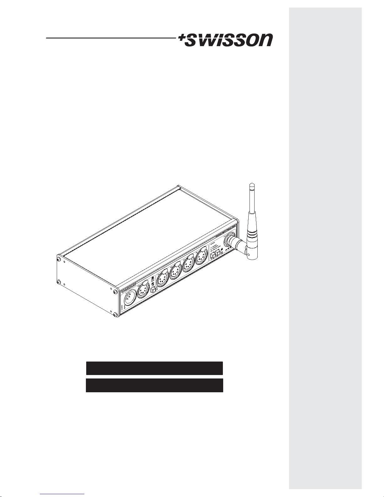
DMX Splitter / Booster,
Wireless DMX Transmitter &
Wireless DMX Receiver
USER MANUAL
BEDIENUNGS ANLEITUNG
Page 2
Page 3
1
E
English
D
Deutsch
Description DateRevision
Revisions History
Copyright © 2012 SWISSON AG
First Draft 24.04.20121
Minor Corrections 24.05.20122
Page 4
The XSW series Wireless DMX splitter/boosters from SWISSON can be easily and
economically integrated into any lighting system where you wish to transmit DMX signal
wireless. The XSW acts in the same time as DMX spiltter and DMX booster.
The XSW can be used as DMX splitter, DMX wireless transmitter or as DMX wireless
receiver.
The XSW can be used as a simple wireless link connecting a tranmitter to one or more
receivers.
All inputs and output ports on the XSW are optically isolated. A strong power supply
allows a reliable operation in a wide voltage range. Multiple XSW devices are available;
with altering housings and connector types.
Introduction
XSW
DMX Splitter, Wireless DMX Transmitter &
Wireless DMX Receiver
!
!
!
Theater
TV Sets
Theme Parks
Applications
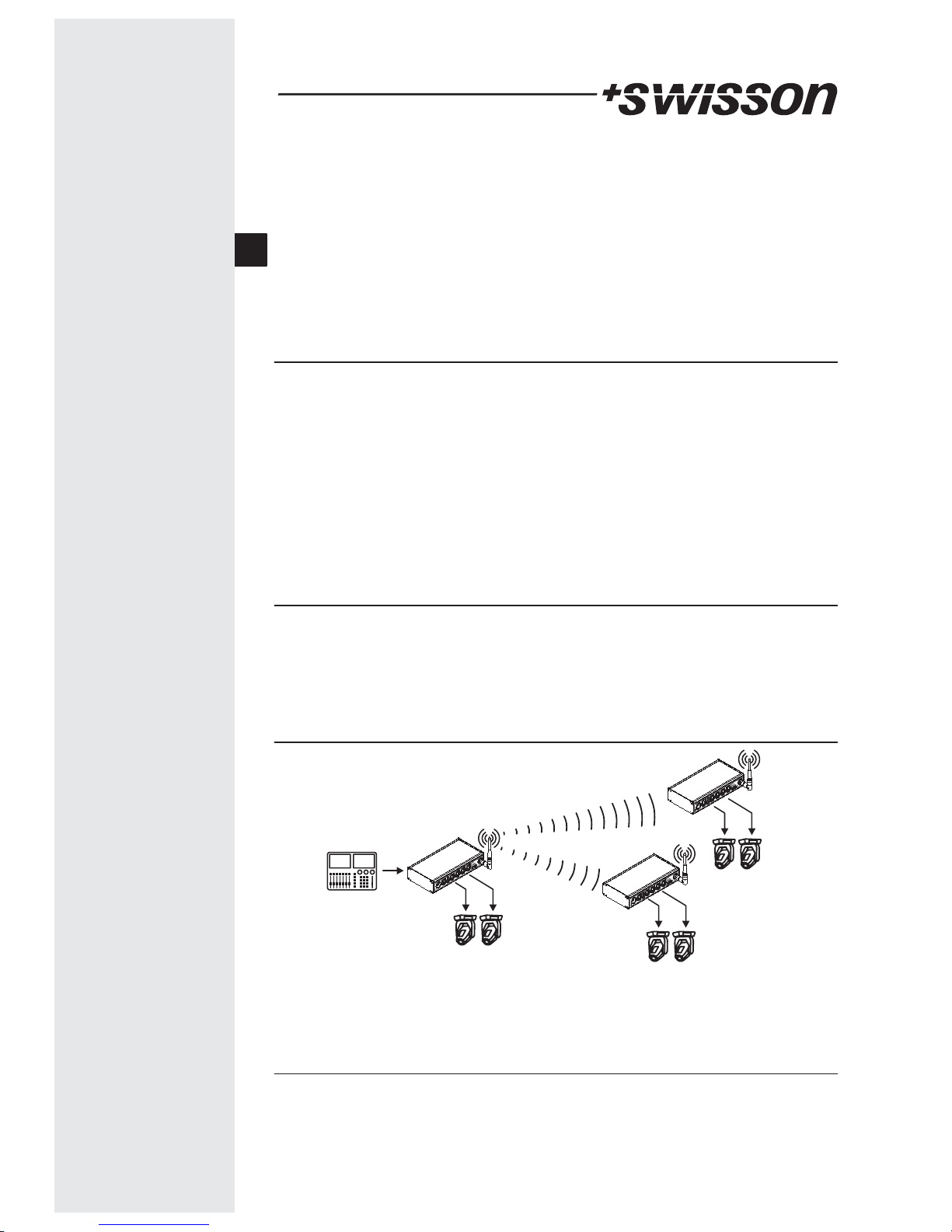
Typical Application
!
!
!
Concert Lighting
Live Events
Multimedia Shows
2
Unpacking
The XSW is packaged in a cardboard box. The following items are included:
-Thedevice
- This user manual
- 1 antenna (2 antennas for double rack versions)
Transmitter
Receiver mode
Receiver mode
Light controller
board
E
Page 5
Safety Information
Consider the following notes absolutely when you set up, connect and use the XSW.
This product is not for household use. Read this manual before operating the device,
follow the safety precautions and observe all warnings in this manual.
Use this device only in accordance with local laws and regulations.
Do not use the device in areas where it is exposed to direct sunlight.
Do not use the device in areas that are considered to be 'highly combustible'.
Safety precautions
!
!
!
!
!
!
!
!
!
!
!
!
!
!
!
!
!
!
!
Disconnect the device from AC power before removing any cover or part, including
fuse and when not in use.
Ensure that the device is electrically connected to ground (earth).
Use only a source of AC power that complies with local building and electrical codes
and has both overload and ground-fault (earth fault) protection.
Connect the Devices to AC power using the supplied power cable.
Before using the device, check that the power distribution equipment and cables
are in perfect condition and rated for the current required of all connected devices.
Isolate the device from power immediately if the power cable or power plug in any
way damaged, defective or wet, of if they show signs of overheating.
Do not expose the device to rain or moisture.
Do not operate the device if any cover or component is missing damaged or
deformed.
Refer any service operation not described is this manual to Swisson.
Provide unrestricted airflow arround the device
Do not operate the device if the ambient temperature exceeds 55 C (131 F)
Do not modify the device in any way not described in this manual or install other
than genuine Swisson parts.
Do not attempt to bypass fuse. Replace defective fuse with one of the specified
type and rating only.
When suspending the device, ensure that the supporting structure and all hardware
used can hold at least 10 times the weight of all devices suspended from them.
Install as described in this manual a secondary attachment such as a safety cable
that is approved by an official body such as TÜV as a safety attachment for the total
weight it secures. The safety cable must comply with EN 60598-2-17 Section 17.6.6
and be capable of bearing a static suspended load 10 times the weight of the
device.
Check all external covers and rigging hardware are securely fastened.
Block access below the work from a stable platform whenever installing, servicing
or moving an overhead device.
°°
3
E
Page 6
4
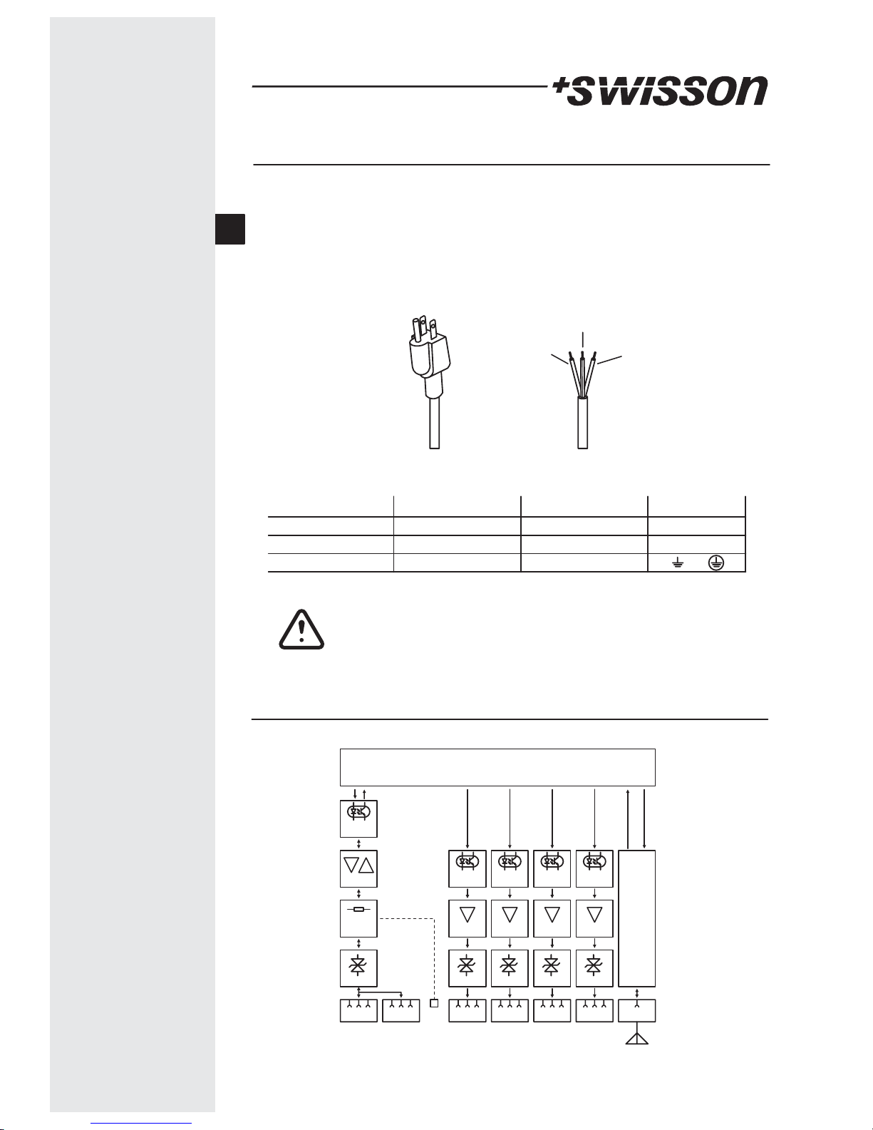
Mains Connection
Two different mains connections are available:
The US versions are delivered by Swisson with a "Edison Plug" (NEMA-5-15). These
models has a "-US" suffix
The International versions are delivered without any plug.
Swisson distributors or dealers may deliver the devices with a country specific plug.
US Versions (-US suffix) International Versions
Brown : Phase Blue : Neutral
Yel l ow/ G re e n : Ea r th
Neutral
Live
Wire (US System)
Ground (Earth)
Wire (EU System) Symbol
L
N
or
black
white
green
brown
blue
yellow/green
Consult a qualified electrician if you have any doubts about proper
installation.
The socket where the device is plugged in must be close to the device
and easily accessible.
ProtectionProtectionProtectionProtection
Optical
Isolation
Optical
Isolation
Optical
Isolation
Optical
Isolation
Control Logic
Protection
Transceiver
Out Port 4Out Port 3OutPort 2Out Port 1In Port Thru Port
Line
Termination
Termination
TransmitterTransmitterTransmitterTransmitter
XSW Block Diagram
Optical
Isolation
HF
Antenna
E
Page 7
5
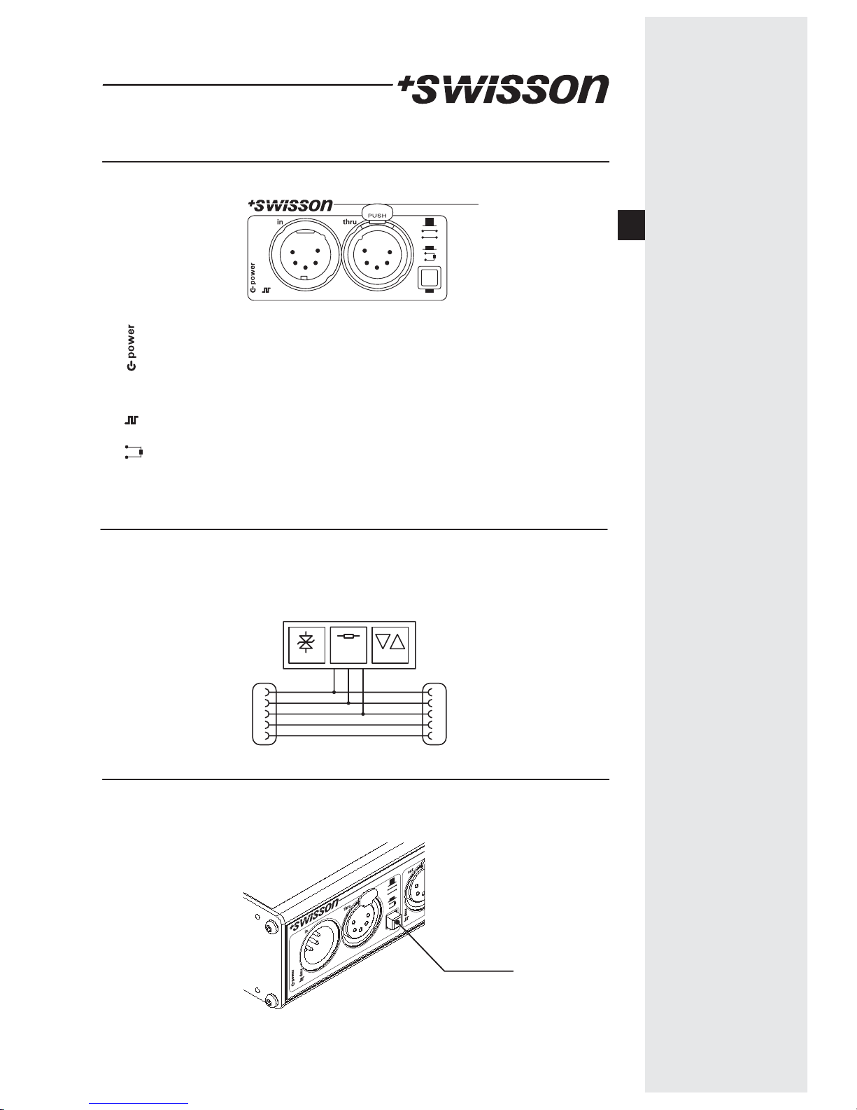
The Power LED shows if the device is powered when the power supply unit of
the XSW is working
A green LED shows if a DMX signal is available at the input port. A red LED
shows if the received signal is faulty.
The XSW has a built in line termination. This can be activated by pressing the
termination button. A LED shows if the termination is activated.
Input Section
dmx
dmx
Input and Thru Port
Protection Transceiver
Line
Termination
Input Port Thru Port
The Thru port is hardwired with the INPUT port and allows to daisy-chain the devices
even when the XSR is not powered. On XSW models with 5-Pin XLR connector, the pins 4
and 5 are also looped thru to the Thru port. On all other models pin 4 & 5 are not
available.
1
2
3
4
5
1
2
3
4
5
Line Termination
All XSW models have a built-in line termination. The termination is activated by pressing
the termination button.
Line Termination
E
Page 8
6
Output Ports
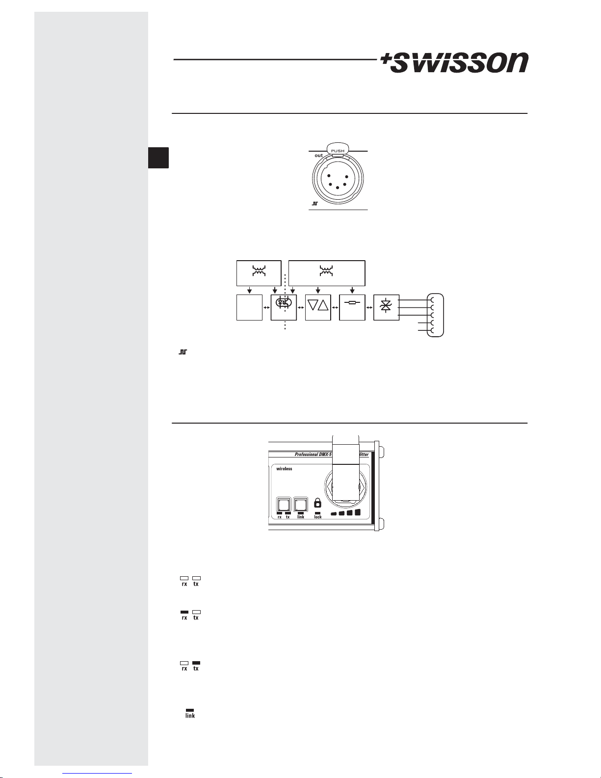
The output section
Each output port is individually optically isolated, meaning that it is totally isolated from
the other output ports and the input selection.
The pins 4&5 on the models with 5-Pin XLR connectors are not connected.
Output Port
1
2
3
4
5
ProtectionTranceiver
Optical
Isolation
Port Supply
Control
Logic
Controller Supply
n.c.
Bias
Network
The signal LED of the output ports show if a valid signal is transmitted.
In Spitter and Wireless Transmitter mode it depends of the signal of the DMX
input port. In Wireless Receiver mode it depends of the DMX received from the
wireless unit.
Wireless Port
The wireless port can be configured as transmitter or receiver. It can also be turned off to
use the XSW as a DMX splitter only.
rx : receiver
tx : transmitter
link : press
unlink : press 3sec
Splitter Only Mode. When both LEDs rx and tx are off, the XSW operates as a
Splitter only. The Wireless port is switched off.
Receiver Mode. When the rx LED is on, the XSW operates a wireless receiver.
The received DMX data is forwarded to the DMX output ports.
The DMX input port has no func tion in this mode.
Transmitter Mode. When the tx LED is on, the XSW operates as a wireless
tranmitter. The DMX data from the DMX input port is transmitted and is also
available at the DMX output ports.
Link. The link button is used to link a transmitter to one or multiple receivers
The link LED shows if the device is linked.
E
Page 9
7
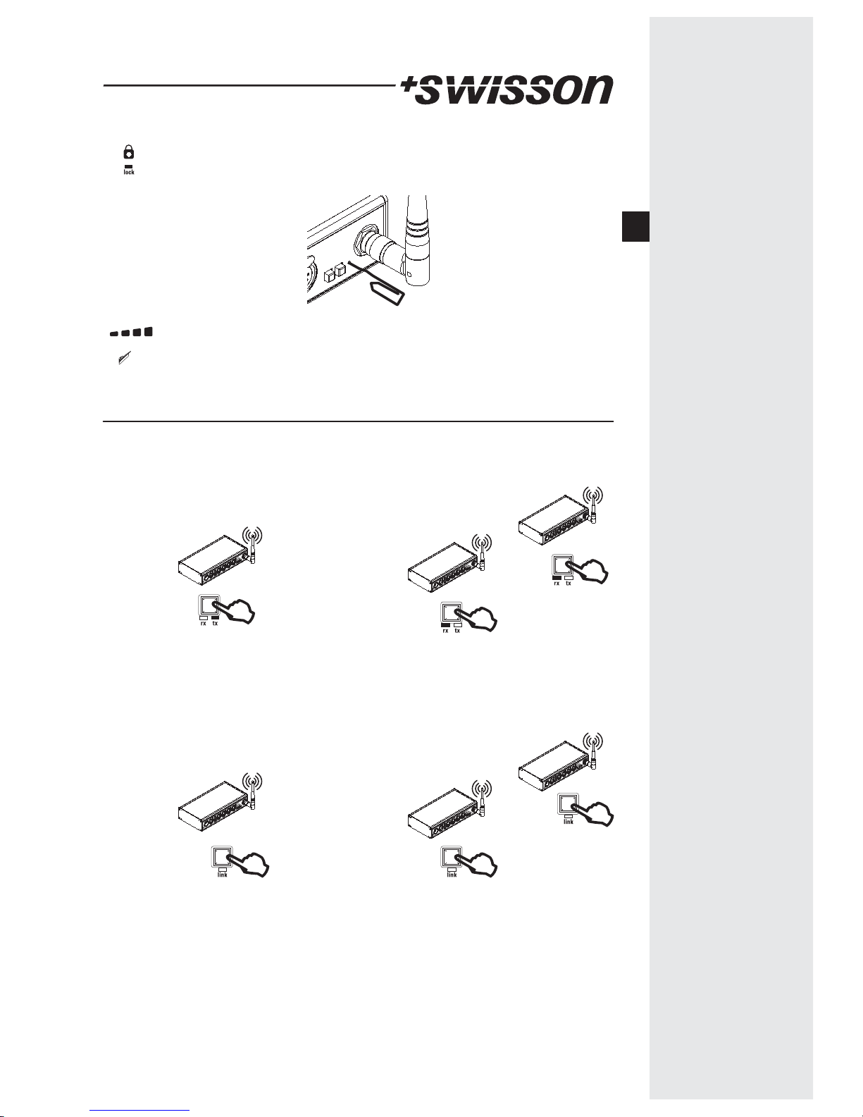
Lock. A red LED shows if activated. In this case, the mode (rx/tx) and the link
buttons are locked. This prevent from an unintended manipulation during
operation. The button is only accessible with a tool.
Signal strength. In Receiver mode four green LED shows the signal strength.
In Transmitter mode a chaser shows the tranmitter is active.
Setup a wireless link
To transmit DMX data wireless, a Transmitter and one or more receives are used. The
receiver have to be liked to the Transmitter.
Transmitter mode
1) Press the mode button multiple
time until the tx LED is on to select
the transmitter mode.
2) On receivers:
Press the mode button multiple
time until the rx LED is on to select
the receiver mode.
4) On receivers:
The receiver might be already
linked to another transmitter from
a past usage. In this case, the link
LED is blinking.
Press and hold the link button for
3 seconds to unlink the device.
Receiver mode
Receiver mode
Transmitter mode
Receiver mode
Receiver mode
3sec
3sec
3) On transmitter:
Press and hold link button for 3
seconds to unlink all devices
previousely linked to the
transmitter.
3sec
E
Page 10
8
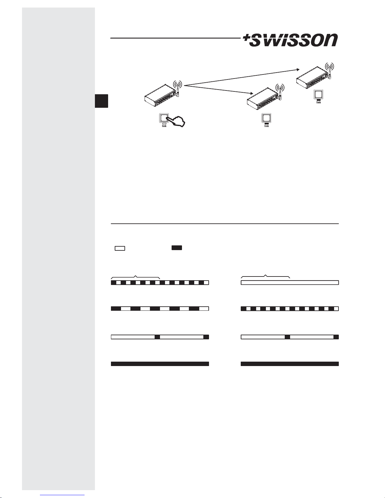
6) On receivers:
The link LED blinks during link
operation. The link LED turns
permaently on when the link is
established and DMX is received
from the transmitter.
Short pulses on the link LED shows
the link is established but no DMX
data is received.
Transmitter mode
5) On transmitter:
Press link button to link all
unlinked receivers in the range of
the transmitter
Link
Link
Link LED
Link in process
Unlink in process
Linked (no DMX)
Linked (DMX ok)
1sec
Led off Led on
Transmitter mode Receiver mode
Linked (no connection to tranmitter)
1sec
Unlinked
Linked (no DMX)
Linked (DMX ok)
The link LED shows different status information depending on the mode.
E
Page 11
9
Multiple links
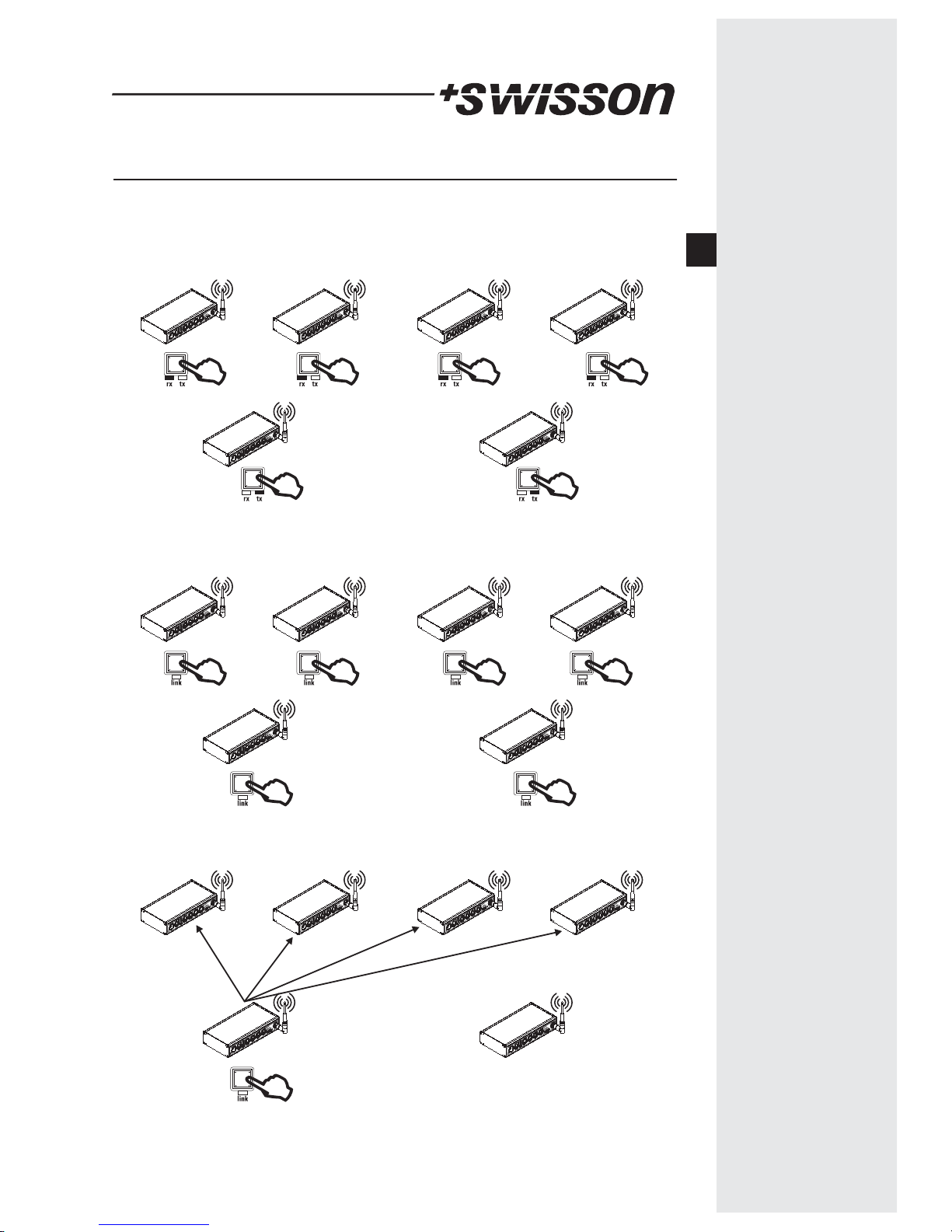
Multiple DMX universe can be used by using multiple links.
Transmitter mode
Receiver mode
Receiver mode Receiver mode Receiver mode
Transmitter mode
1) Configure the units to their corresponding mode. Transmitter or receiver.
2) Unlink all devices from previous links
Transmitter mode
Receiver mode Receiver mode Receiver mode Receiver mode
Transmitter mode
3sec 3sec 3sec 3sec
3sec3sec
3) Link first universe by pressing the link button on the first transmitter. It will link to all
unlinked receivers.
Transmitter mode
Receiver mode Receiver mode Receiver mode Receiver mode
Transmitter mode
E
Page 12
10
Tranmitter mode
Receiver mode Receiver mode Receiver mode Receiver mode
Tranmitter mode
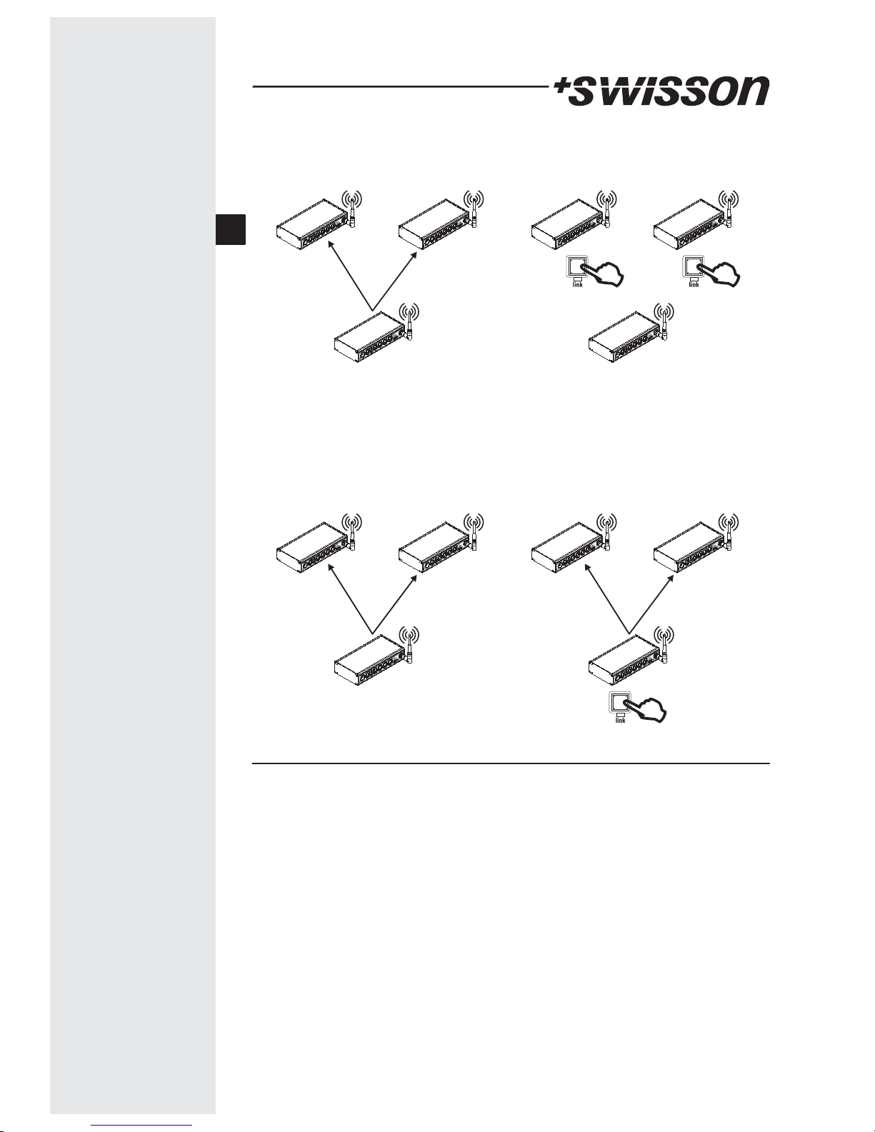
Note: You can switch the receivers you want to link to the secondary transmitter
temporarily to Splitter only mode or you can switch them off. This prevent to unlink this
receivers from the first transmitter.
3) Unlink receivers you want to link to the second transmitter.
3sec 3sec
4) Link second universe by pressing the link button on the second transmitter. It will link
to all unlinked receivers.
Transmitter mode
Receiver mode Receiver mode Receiver mode Receiver mode
Transmitter mode
Limits on multiple links
Each transmitter needs bandwidth and there might be a lot of other devices like
WIFI using the same frequency band. It’s not recommended to use more than 4-6
transmitters on the same site.
There is no limitation for the numbers of receivers linked to a transmitter.
also
E
Page 13
11
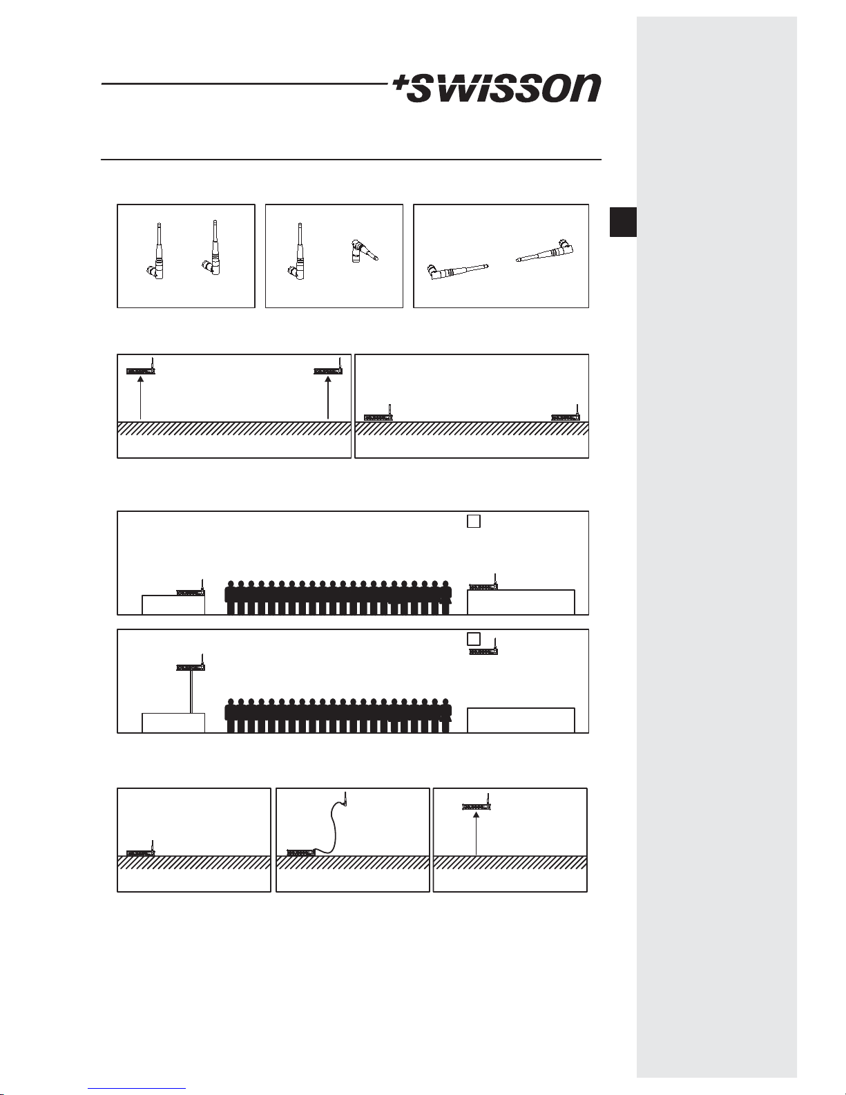
Position of the Antenna
Try to position the antennas in parallel.
Good Not good Bad
Good Bad
Try to position the antenna as high as possible. Avoid to operate the XSW near ground.
Try to position the antennas as high as possible. A crowd will absorb the signal.
Bad
Good
It’s better to position the device as high as possible than of using an antenna cable.
Bad Better Best
E
Page 14
12
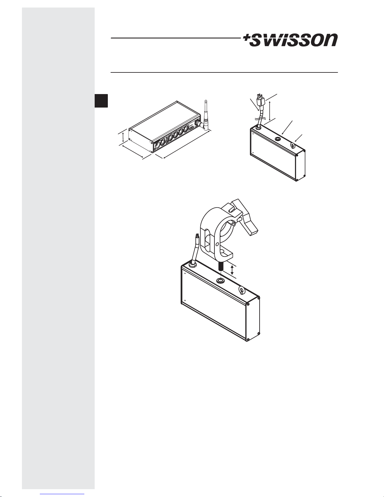
XSW Box Models
Mains cable
M10 female threat for
Eye for safety
Cable length approx.
217.5mm
Mains plug (US-Versions
112mm
45mm
The length of the M10 screw which enters the XSW should not exceed a maximum of
20mm.
Clamp is not included with the XSW
20mm MAX
E
Page 15
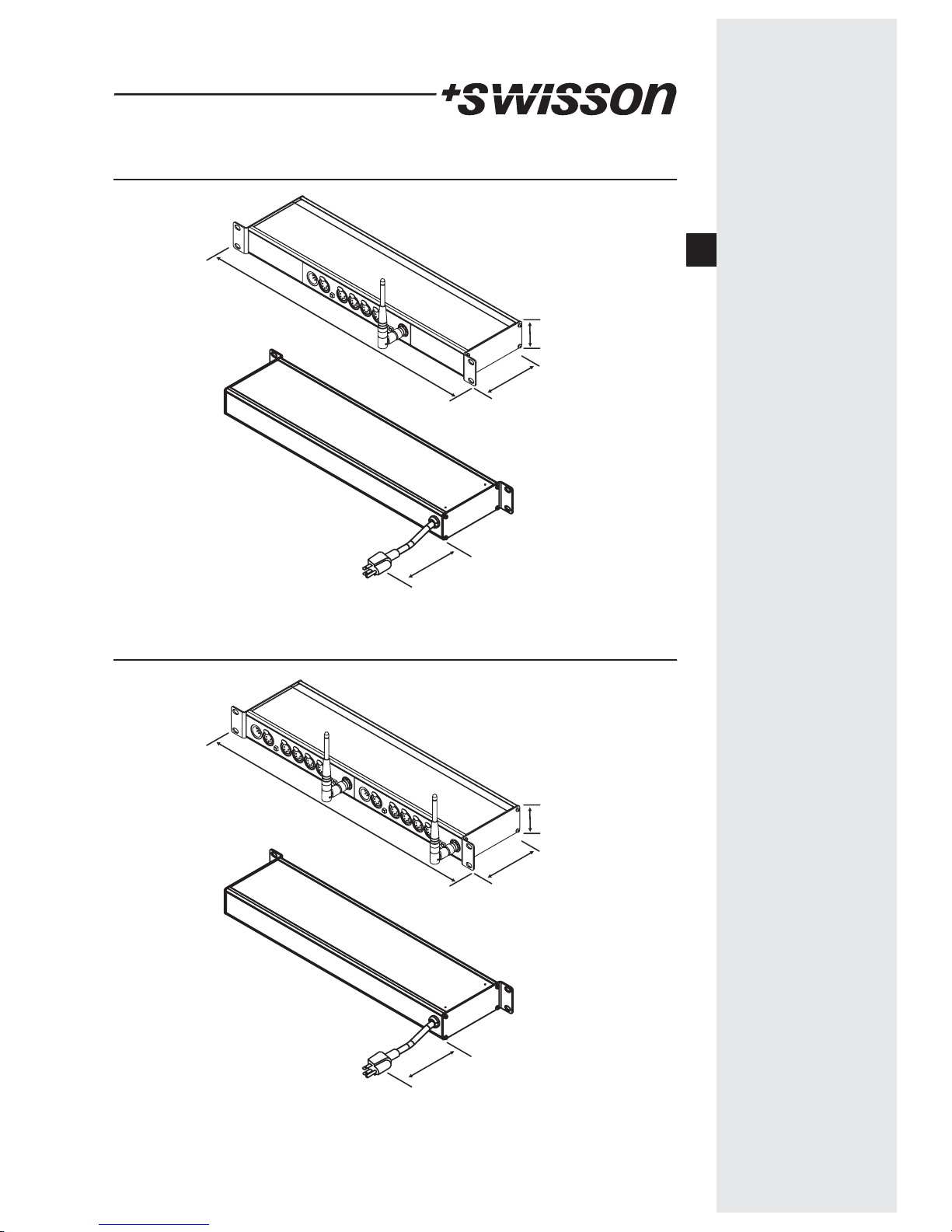
XSW Single Rack Models
13
482mm
112mm
45m
cable length approx. 145cm
Mains plug (US-Versions only)
XSW Double Rack Models
482mm
112mm
45m
cable length approx. 145cm
Mains plug (US-Versions only)
E
Page 16
14
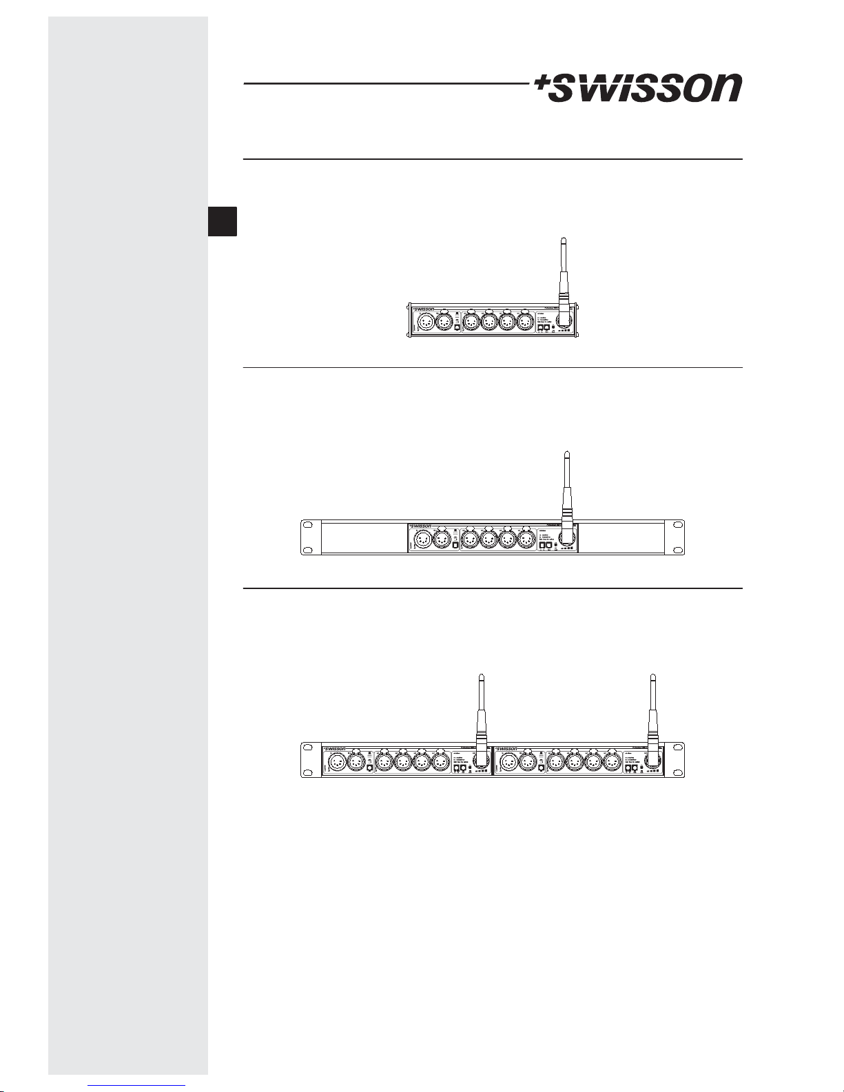
XSW box versions
10 18 10 XSW-3B 3pin XLR
11 18 10 XSW-3B-US 3pin XLR, with NEMA 5-15
10 18 11 XSW-5B 5pin XLR
11 18 11 XSW-5B-US 5pin XLR, with NEMA 5-15
10 18 20 XSW-3R 3pin XLR
11 18 20 XSW-3R-US 3pin XLR, with NEMA 5-15
10 18 21 XSW-5R 5pin XLR
11 18 21 XSW-5R-US 5pin XLR, with NEMA 5-15
XSW rack versions
10 18 30 XSW-3R-3R 3pin XLR
11 18 30 XSW-3R-3R-US 3pin XLR, with NEMA 5-15
10 18 31 XSW-5R-5R 5pin XLR
11 18 31 XSW-5R-5R-US 5pin XLR, with NEMA 5-15
XSW double rack versions
E
Page 17
15
Technical Data
Mains Voltage 100 - 240
Main Frequency 50/60 [Hz]
Current Consumption
Single Units 0.3 [A]
Operating Temperature 0F to 131F (-17 C to 55 C)
Protocol Standard ANSI E1.11 (DMX-512)
[VAC]
Current Consumption
Double Units 0.5 [A]
°°
No part of this documentation may be reproduced or transmitted in any form or by any
means, electronic or mechanical, including photocopying and recording, without the
prior written permission of SWISSON AG.
The information in this documentation is supplied without warranty of any kind, either
directly or indirectly, and is subject to change without prior written notice. SWISSON its
employees or appointed representatives will not be held responsible for any damages to
software, hardware, or data, arising as a direct or indirect result of the product(s)
mentioned herein.
Issued by
SWISSON AG SWISSON of AMERICA Corp.
Fabrikstrasse 21 2419 East Harbor Blvd. #34
CH-3250 Lyss Ventura, CA 93001
Switzerland U.S.A.
E
 Loading...