

Page 1
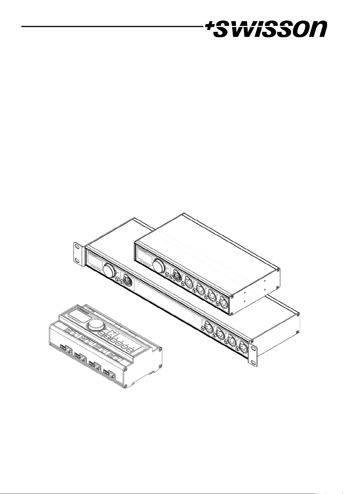
XND-4
4-Port Ethernet DMX Node
User Manual
Page 2

UM_XND-4-D0-LEN-V01-07-DRAFT.DOCX 2020-09-22
Page 3

3
Index
Index .................................................................................................................................................................................. 3
Introduction ...................................................................................................................................................................... 4
Unpacking ......................................................................................................................................................................... 4
Safety Information ............................................................................................................................................................ 5
Device Overview ............................................................................................................................................................... 7
Settings and Menu .......................................................................................................................................................... 10
Status LEDs ...................................................................................................................................................................... 25
Screen Saver .................................................................................................................................................................... 26
Firmware Updates ........................................................................................................................................................... 26
Web Interface ................................................................................................................................................................. 27
Technical Data ................................................................................................................................................................. 29
Ordering Information ...................................................................................................................................................... 31
Credits ............................................................................................................................................................................. 31
Appendix ......................................................................................................................................................................... 32
Page 4
4
Introduction
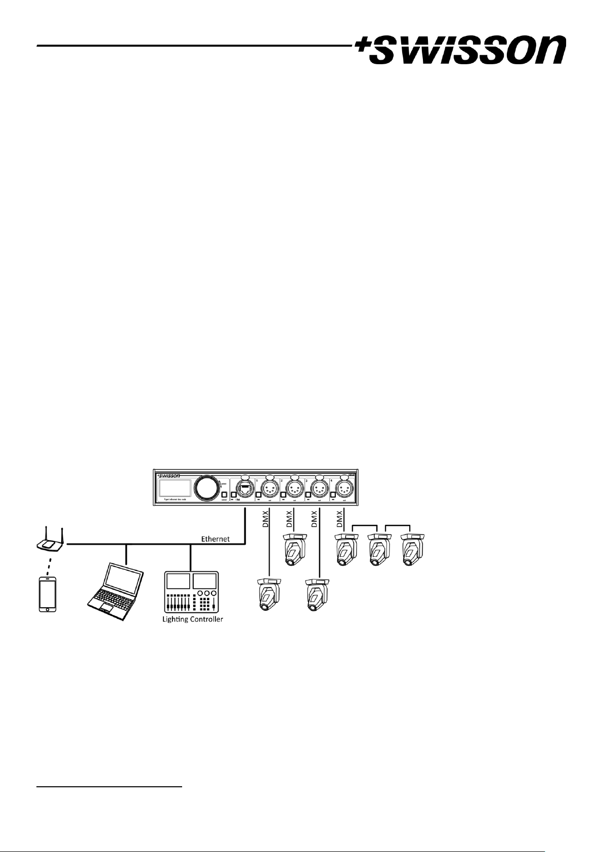
XND-4 is a user-friendly Art-Net and sACN to DMX converter supporting the distribution of four universes of DMX via
four individually optically isolated DMX ports, each of which is independently configurable as an input1 or output.
Since most major lighting consoles are capable of transmitting Art-Net data, the XND-4 is all you need to take
advantage of your console’s networking capability, allowing you to transmit a vast number of universes over one
single network cable. In some cases, users may profit from already existing networking infrastructure.
Furthermore, the XND-4 is also perfectly suited to send DMX data to your fixtures from a computer or even from a
mobile device. Many light controller programs for PC or Mac support Art-Net output natively and with the help of
XND-4’s DHCP capability, you can even let your workplace network infrastructure do the network configuration of
your XND-4 automatically for you.
With its 128x64 pixels OLED display however, configuring the network and setting up your Art-Net or sACN
preferences manually is no trouble at all and helpful status information is always at hand.
Applications
• Concert lighting
• Live events
• Multimedia shows
• Theaters
• TV studios
• Theme parks
• Architectural lighting
Typical Application
Unpacking
The XND-4 is packaged in a cardboard box. The following items are included:
• The device.
• This user manual.
1
Input mode only available on devices produced after 2017 (hardware rev. 1.0-b)
Page 5

5
Safety Information
It is essential that you read and understand this manual before operating the device and that you
follow the instructions given below closely when you set up, connect and use the XND-4. Do not
use the device in any way or for any purpose not described in this user manual.
This product is approved for professional use only; it is not intended for household usage. Pay
attention to all warnings given in this manual and use this device only in accordance with
applicable laws and regulations.
Safety Precautions
• Disconnect the device from the power supply before removing any cover or part, including
fuses, even when not in use.
• Ensure that the device is electrically connected to ground (earth).
• Use only a source of power supply that complies with local building and electrical
regulations and which has both overload and ground-fault (earth fault) protection.
• Before using the device, check that the power distribution equipment and cables are in
perfect condition and rated for the current required by all connected devices.
• Isolate the device from power supply immediately if the power cable or the power plugs
are in any way damaged, defective or wet, or if they show signs of overheating.
• Do not expose the device to rain or moisture.
• Do not operate the device if any cover or component is missing, damaged or deformed.
• Refer any service operation not described in this manual to Swisson.
• Provide unrestricted airflow around the device.
• Do not operate the device if the ambient temperature exceeds 55°C (131°F).
• Do not modify the device in any way not described in this manual or install other than
genuine Swisson parts.
• Do not attempt to bypass any fuse. Replace any defective fuse with one of the specified
type and rating only.
• When suspending the device, ensure that the supporting structure and all hardware used
can hold at least 10 times the weight of all devices suspended together.
• When suspending the device, install a secondary attachment such as a safety cable that is
approved by an official body such as, e.g. TÜV (German Technical Monitoring Association),
a safety attachment for the total weight it secures. The safety cable must comply with EN
60598-2-17 section 17.6.6 and be capable of bearing a static suspended load 10 times the
weight of the device.
• Make sure that any external cover and rigging hardware is securely fastened.
• Provide an adequate clearance underneath the work area and a stable platform whenever
installing, servicing, or moving an overhead device.
Page 6

6
• Do not use the device in areas where it is exposed to direct sunlight.
• Do not use the device in areas that are “highly inflammable”.
Page 7
7
Device Overview
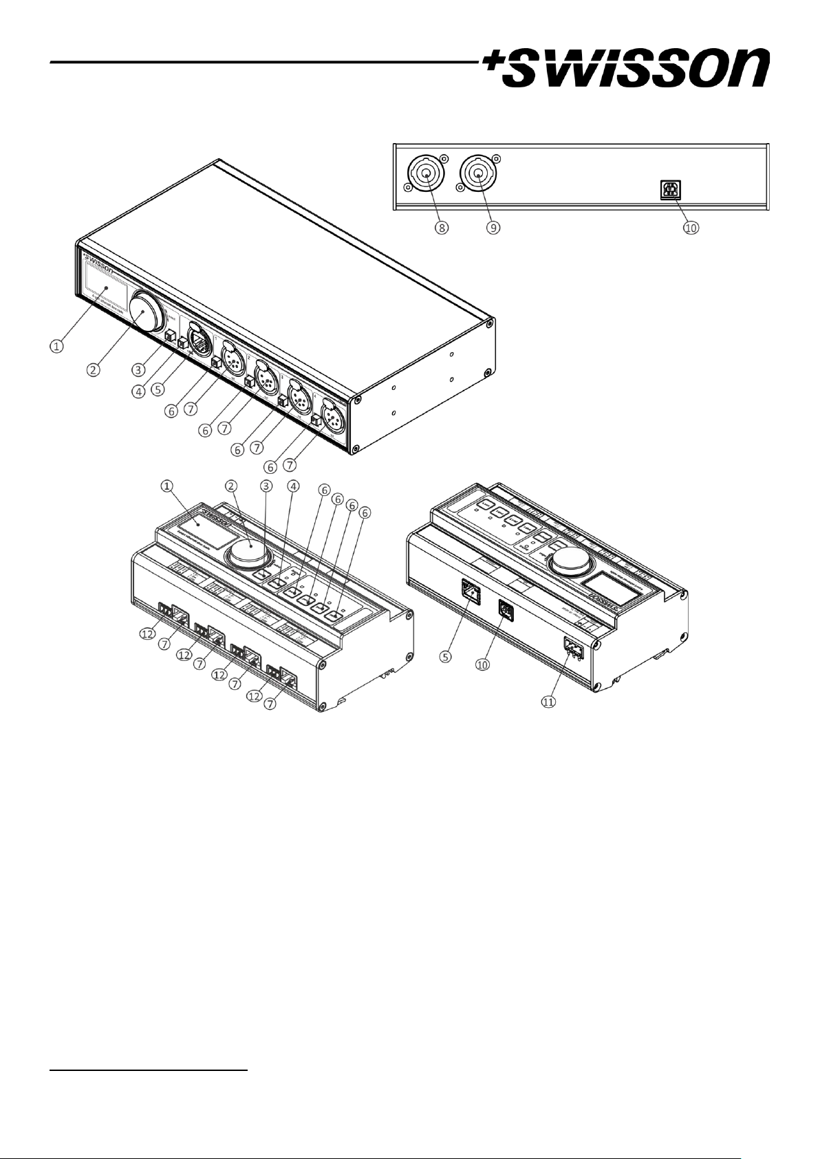
1. OLED display.
2. Encoder wheel / [OK] button. The encoder is primarily used for selecting menu items by turning the knob. It
also functions as a push button. This manual refers to this button simply as [OK] button or [OK].
3. [Cancel] button.
4. Ethernet port button [E].
5. Ethernet port (RJ45 Neutrik etherCON socket on rack and truss mountable models, regular RJ45 socket on
XND-4D).
6. Port buttons [1] – [4]. These push buttons are used to open the port menu of the corresponding port. A port
status LED showing status information is located directly below each of those buttons (above for XND-4D).
7. Signal output and input1 ports 1 – 4.
8. Neutrik powerCON input socket.
9. Neutrik powerCON output socket.
10. USB type-B socket for firmware updates.
11. Power supply input.
1
Input mode only available on devices produced after 2017 (hardware rev. 1.0-b)
Page 8
8
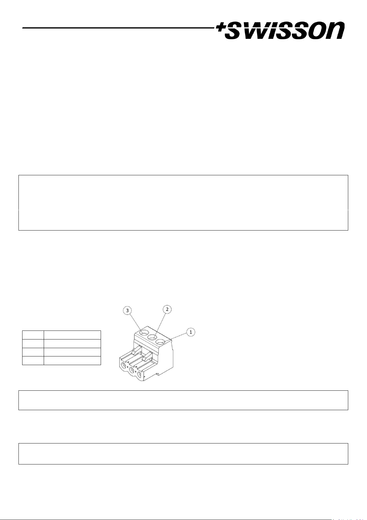
12. Signal output and input ports 1 – 4 box header connectors. On the XND-4D, a box header and a RJ45
connector is available for each DMX port. Please note that only one of the two sockets should be used at a
time.
Power Supply
Mains Connection XND-4
The following does not apply to the XND-4D which is powered via an external power supply unit. To power regular
XND-4 models the user must supply a suitable power cable. He may then either hard-wire the power cable to the
building’s electrical installation, providing an easily accessible power on/off switch close to the device, or install on the
power cable a grounding-type (earthed) mains plug that is suitable for the local power outlets, following the power
plug manufacturer’s instructions. Consult a qualified electrician, if you have any doubts about the proper installation.
A blue Neutrik powerCON NAC3FCA cable mount connector must be used to supply power at the XND-4’s power input
socket.
Warning! For protection against dangerous electrical shocks, the device must be grounded (earthed). The
local AC power source must be supplied with both overload and ground-fault (earth fault) protection.
Important! Only attach or remove a Neutrik powerCON connector while it is connected to the mains to
apply or cut power in an emergency, as by doing so may cause arcing at the terminals that will damage
the connectors.
PSU Connection XND-4D
For the XND-4D a suitable power supply unit that meets the following conditions, must be supplied by the user:
• Stabilized DC output voltage: 10 V – 48 V
• Power: 4W
It is not strictly required but highly recommended to properly connect the ground pin to earth. Not connecting the
ground pin may affect the performance of the device.
…….
Warning! For protection from dangerous electric shocks, the device must be grounded (earthed). The local AC power
source must have both overload and ground-fault (earth fault) protection.
Power Outlet
The following is applicable to mains powered XND-4 models with a Neutrik powerCON outlet.
Warning! The total current load of all devices connected to the AC mains power outlet of the XND-4 must
not exceed 19.8 amperes.
• A power cable that meets the requirements specified in the safety instructions section of this manual must be used
to connect the XND-4 to AC mains power and to connect other devices to the power outlet.
Pin
Connection
1 + 2 - 3
Earth
Page 9
9
• A light-grey Neutrik powerCON NAC3FCB cable-mount connector must be used to draw AC mains power from the
XND-4’s power outlet.
• No matter what the AC mains power voltage is, the current drawn by all the devices that draw AC mains power from
the power outlet of an XND-4 must not exceed a total of 19.8 amperes.
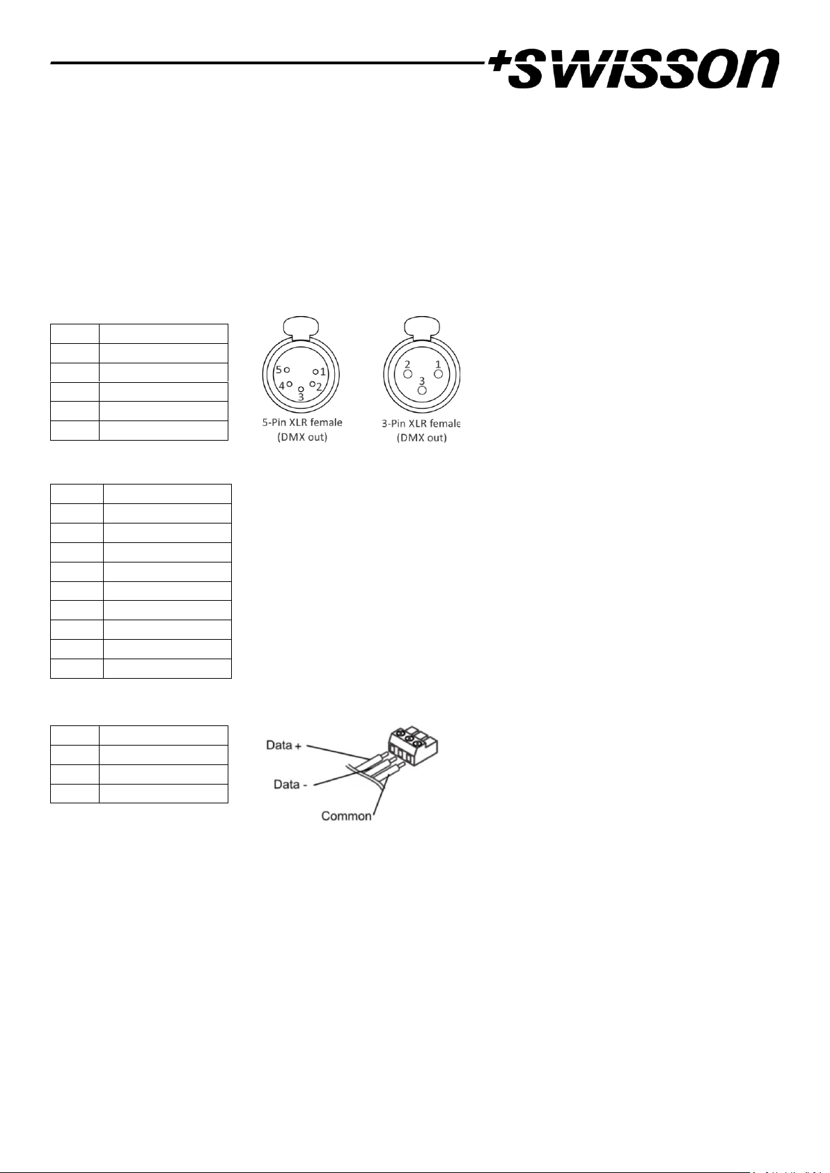
DMX Connections
Depending on the version, the XND-4 is equipped with 5-pin or 3-pin XLR connectors, with RJ45 connectors or 3-pole
box header connectors.
XLR Connectors
RJ45 Connectors
Box Header Connectors
Each port is individually optically isolated.
On the XND-4D, a box header and a RJ45 connector is available for each DMX port. Please note that only one of the
two sockets should be used at a time. Also, there is no isolation between the sockets that belong to the same DMX
port.
Pin
Connection
1
Com
2
Data -
3
Data +
4
Not connected
5
Not connected
Pin
Connection
1
Data +
2
Data -
3
Not connected
4
Not connected
5
Not connected
6
Not connected
7
Com
8
Com
Shield
Earth
Pin
Connection
1
Data +
2
Data -
3
Com
Page 10
10
Settings and Menu
General Navigation
The encoder wheel (see page 7) is the primary means for navigating through the menus. Most of the menus arrange
items vertically. In those menus, turn the encoder clockwise to select the item below the currently selected item or
turn the encoder counterclockwise to select the item above the currently selected item. In menus that arrange items
horizontally (e.g. text fields), clockwise means “to the right” and counterclockwise means “to the left”.
Other than that, the encoder wheel also functions as a push button. This button is generally used to confirm a selection
or to navigate to a selected submenu. This manual will also refer to pushing the encoder knob as “pushing [OK]” or
“pushing the [OK] button”.
On the right side of the encoder knob, you can find the [Cancel] button (depicted on page 7), which is generally used
to dismiss a selection or to exit a menu.
By keeping the [Cancel] button pressed for at least two seconds, you can always navigate to the Home Screen. From
the Home Screen, the menu is launched by simply pushing the [OK] button.
The following notation is used to describe locations in the menu: Home > Menu > Sub menu > …
For example, the manual could say “navigate to Home > Menu > Art-Net”. This can be read as follows:
Keep [Cancel] pressed for 2 seconds to reach the Home Screen.
Then, press [OK] to get to the menu.
Select Art-Net using the encoder wheel.
After pressing [OK] again to confirm the selection, the Art-Net settings menu is displayed.
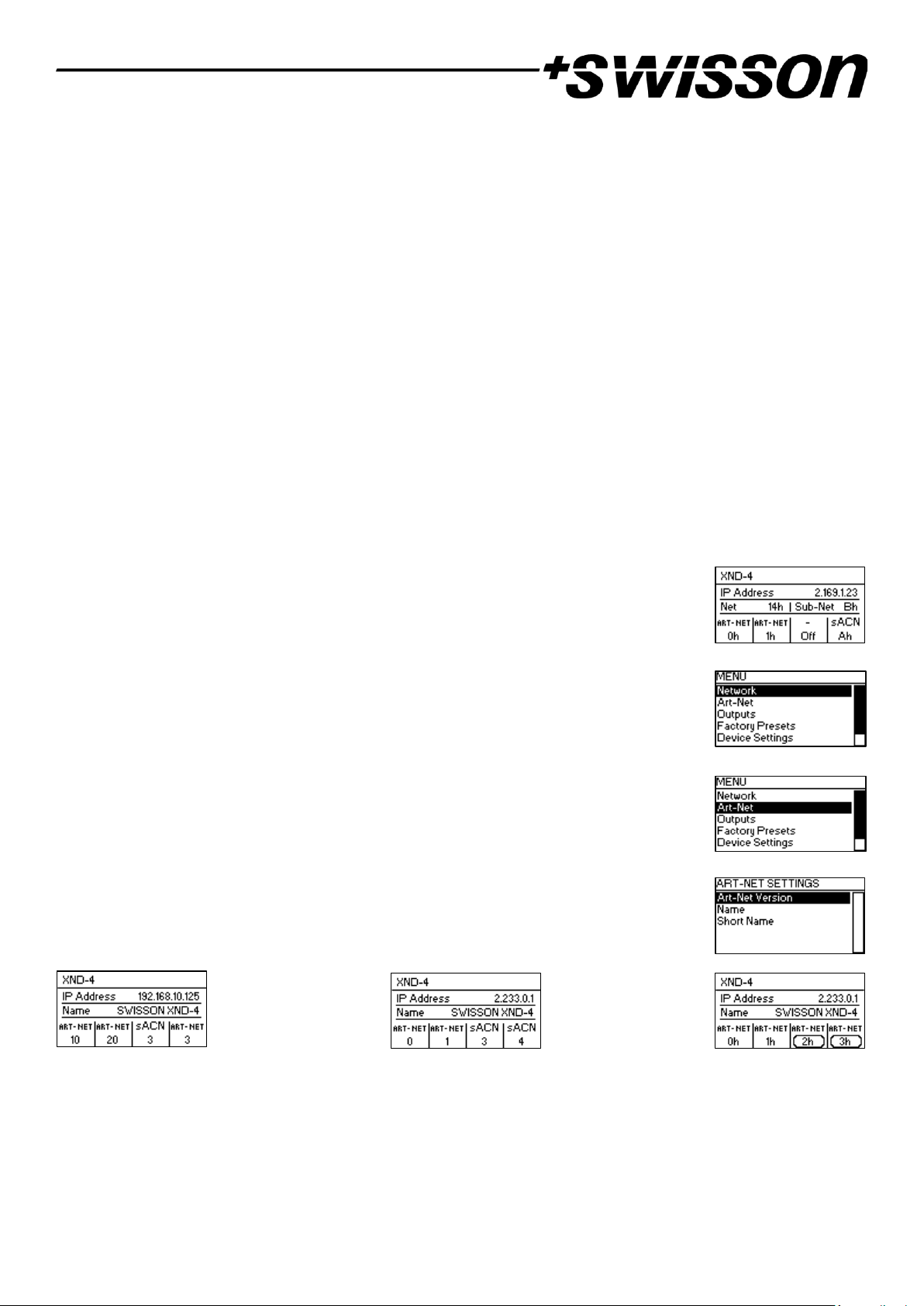
Home Screen
XND-4 Home Screen with
ports 1-2 configured to
output Art-Net and ports
3-4 to output sACN.
Decimal universe
addresses.
Home Screen indicating
that no signal is applied
to either of the input
ports.
XND-4 Home Screen with
ports 1-2 configured to
output Art-Net and ports
3-4 as Art-Net inputs.
Hexadecimal universe
addresses.
Home Screen of an XND-4
running in Art-Net 4
mode, configured to a
custom IP address
(192.168.10.125) with
Art-Net and sACN
universe addressing
information displayed in
decimal.
Page 11
11
The Home Screen shows the IP address of the node and, depending on the firmware version and configuration of the
node, also the Art-Net net and the Art-Net sub-net of the node or the Art-Net name (see section Name on page 14).
The Art-Net name is displayed if the device has firmware version 1.01 or later and the Art-Net version of the device is
set to Art-Net 4 (see Art-Net Version on page 13).
The numbers at the bottom of the screen display the 4-bit Art-Net universe of each each output port running in ArtNet mode if independent Art-Net universes are disabled (see Independent Universes on page 14) or if the Art-Net
version of the node is set to Art-Net 3 if the node is running firmware version 1.01 or later.
If the Art-Net version of the node is set to Art-Net 4 (available with firmware versions 1.01 and newer) or if
independent Art-Net universes are enabled (applicable to devices with firmware version 1.00 and older), Art-Net net
and Art-Net sub-net are not displayed and the numbers at the bottom of the screen that correspond to a port
running in Art-Net mode are values in the range of 0 to 32767. This number fully identyfies a port’s universe and is
also referred to as the port address. For more information on the addressing of Art-Net ports, see section
Representations of Art-Net Port Addresses in the appendix.
For each port running in sACN mode, the 16-bit sACN universe, a number in the range of 1 to 63999, is displayed at
the bottom of the screen. The left most number corrseponds to the universe of port 1.
The universe number of an input port is surrounded by a rounded corner box. A filled box around the universe
number of an input port indicates the presence of a valid DMX signal.
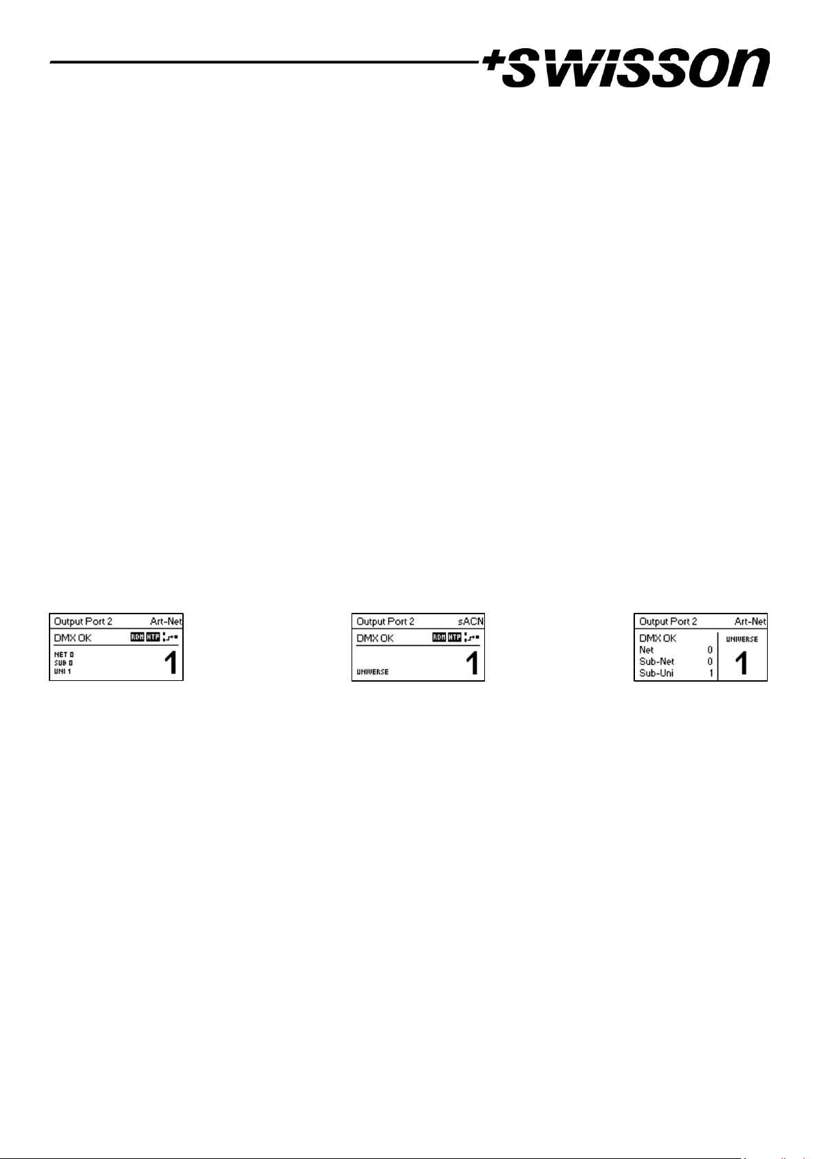
Port Screen
The Port Screen shows information about the selected port. It can be reached by pressing the port button (button [1]
– button [4], see page 7) or by navigating to Home > Menu > Ports > Port X > Universe. There are three variations of
the Port Screen, depending on selected protocol and Art-Net version.
Art-Net 4
sACN
Art-Net 3
This screen can be closed by pressing [Cancel] or [OK]. It will disappear by itself after 20 seconds. When turning the
encoder, universe edit mode is activated. For more information about universe numbering and editing, see section
Universe on page 16.
Depending on the port mode, the label on the top left will show if the selected port is configured as an input or as an
output. A disabled port just shows the port number and a “Port Off” label.
A double tap on the port button will open a reduced port settings menu. This allows fast changes to port specific
settings. See section Port Settings for more information.
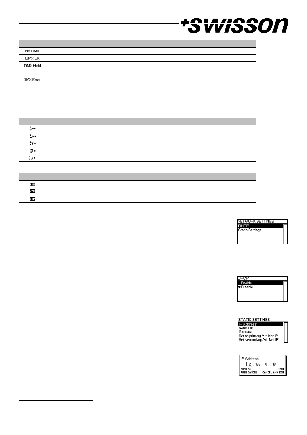
Status Indication
There are several indicators and labels on the Port Screen to show the current operating mode and the state of the
selected port. The following status labels displayed on the upper left of the Port Screen show the DMX signal status:
Page 12
12
Label
Port Mode
Description
in, out
No DMX signal present.
in, out
A valid DMX signal is detected.
out
Port is outputting a look which has been received before, but no updates
have been received for at least 10 seconds1.
in
An error on the DMX signal appeared.
To show additional information about the selected port, there are status indicators for the presence of RDM on
output ports, as well as the merge mode and status on the upper right of the display. These status indicators are only
available with Art-Net 4 and sACN.
Indicator
Port Mode
Description
out
Receiving signal from one source.
out
Receiving signal from two sources. Merger active.
out
Receiving signal from more than two sources. See section Merge Mode.
in
Sending signal to broadcast or multicast address.
in
Sending signal to unicast Address. See section Input Settings.
Indicator
Port Mode
Description
out
Art-Net RDM is enabled.
out
Merger mode is HTP. See section Merge Mode.
out
Merger mode is LTP. See section Merge Mode.
Network Settings
The network settings can be found under Home > Menu > Network or by double tapping the
Ethernet port button.
All following settings can also be changed via web interface on the Network Settings Page as
seen on page 28.
DHCP
Navigate to Home > Menu > Network > DHCP in order to enable or disable DHCP (Dynamic Host Configuration
Protocol). Choose Enable if you want to have your network configured by a DHCP server.
This would typically be the case if you connect the XND-4 to a home or office network.
A bullet point is shown next to the currently active setting. Use the encoder wheel to choose
the desired setting and confirm by pressing [OK] in order to change the setting.
Static Settings
All settings under Home > Menu > Network > Static Settings apply only if DHCP is disabled
and are ignored otherwise. From this menu, you can choose the IP address, the netmask and
the gateway address to be used when DHCP is disabled.
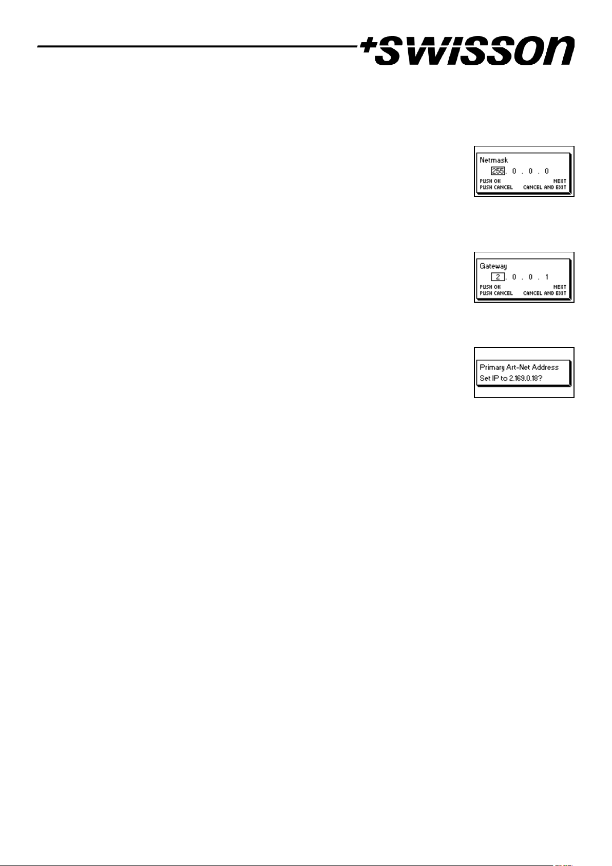
IP Address
Use this menu item to configure the device’s IP address. When the IP address configuration
dialog is opened, it will look just like the dialog depicted to the right. A box encircling the first
number indicates that the first number is selected. While the first number (byte) of the IP
address is selected, use the encoder wheel in order to choose the desired value for the first
byte of the address, then push [OK] to confirm your selection.
1
6 seconds for firmware version 0.93 and earlier
Page 13
13
The next number will become selected allowing you to configure the second number. Simply repeat the same steps
for the remaining numbers. After confirming the value of the last byte, the dialog will be closed, and the new
settings will be applied.
Netmask
In order to configure the netmask, use the same procedure as for configuring the IP address.
The netmask is used internally to compute the network address from the IP address. XND-4
does this by computing the bitwise AND of each byte with the corresponding byte of the IP
address. The bitwise AND of the first byte of the IP address and the first byte of the netmask is the first byte of the
network address and so on.
Gateway
In order to configure the default gateway address, use the same procedure as for configuring
the IP address or the netmask. If the network data sent by the node needs to be routed, you
may want to set this address to the address of your router. In most cases, however, this
setting is not relevant.
Set to Primary Art-Net IP
After navigating to the menu item Home > Menu > Network > Static Settings > Set to primary
Art-Net IP, a dialog as shown on the right will appear. Press [Cancel] to abort or press [OK] in
order to apply the following settings:
… Static Settings > IP Address is set to the primary Art-Net IP address (2.X.Y.Z). The values X, Y
and Z are computed from the device’s MAC address.
… Static Settings > Netmask is set to 255.0.0.0.
Set to Secondary Art-Net IP
As Set to Primary Art-Net IP, but sets network settings to the following values:
… Static Settings > IP Address is set to the secondary Art-Net IP address (10.X.Y.Z).
… Static Settings > Netmask is set to 255.0.0.0.
Art-Net Settings
Node-wide Art-Net settings can be configured under Home > Menu > Art-Net.
Art-Net Version
This section applies to firmware version 1.01 and later.
The menu entry Home > Menu > Art-Net > Art-Net Version provides the following selection:
• Art-Net 4: Select Art-Net 4 to use the advantages of Art-Net 4. This is the recommended setting.
• Art-Net 3: Select Art-Net 3 for backward compatibility.
A bullet point is shown next to the currently active setting. Use the encoder wheel to select the desired setting and
push [OK] to apply the setting.
When Art-Net 4 is selected, each output port has an independent port address in the range of 0 to 32767, which is
composed of an Art-Net net, sub-net and universe number. This allows for configuring the node to any combination
of Art-Net universes. When Art-Net 3 is active, all ports of the node share the same net and sub-net numbers. For
more information on the addressing of the Art-Net ports, see section Representations of Art-Net Port Addresses in the
appendix.
Page 14
14
Net
This setting is only available when the Art-Net version is set to Art-Net 3 or with firmware versions prior to version
1.01.
To adjust the Art-Net net of the node, navigate to Home > Menu > Art-Net > Net and adjust the number using the
encoder wheel. Once the desired number has been selected, push [OK] to apply the new setting or press [Cancel] to
abort.
This part of the Art-Net address was introduced with Art-Net 3. In order to work with Art-Net I and Art-Net II
controllers, Art-Net net needs to be set to 0.
Note that changing this setting while independent Art-Net universes are enabled still affects all Art-Net port
addresses. For more information, see Independent Universes below.
Sub-Net
This setting is only available when the Art-Net version is set to Art-Net 3 or with firmware versions prior to version
1.01.
The Art-Net sub-net is configured under Home > Menu > Art-Net > Sub-Net in the same way the Net is configured.
Note that changing this setting while independent Art-Net universes are enabled still affects all Art-Net port
addresses. For more information, see Independent Universes below.
Independent Universes
This setting is only available with firmware versions that appeared before version 1.01. Newer firmware versions
provide the same functionality when the Art-Net version is set to Art-Net 4. The main advantage of the Art-Net 4
support over the obsolete independent universes functionality is that Art-Net 4 support allows an Art-Net 4 aware
controller to properly understand and, if supported by the controller, configure the port address of each port
whether the ports share a common net and sub-net address or not.
Independent Art-Net universes may be enabled and disabled under Home > Menu > Art-Net > Independent Universes.
If independent Art-Net universes are enabled, the ports of the Art-Net node do not need to share the same Art-Net
net and sub-net addresses.
When this feature is enabled, each output port has an independent port address in the range of 0 to 32767, which is
computed from the Art-Net net, sub-net and universe number. This allows for configuring the node to any combination
of Art-Net universes. However, if the Art-Net net or the Art-Net sub-net settings are changed (remotely or in the
menu), each output port address is recomputed. For more information on the addressing of the Art-Net ports, see
section Representations of Art-Net Port Addresses in the appendix.
Unfortunately, due to restrictions of Art-Net, the node may no longer correctly report the port addresses of its outputs
to a controller when this feature is enabled, which might confuse a controller and lead to problems. Therefore, it is
recommended to avoid enabling independent universes whenever possible.
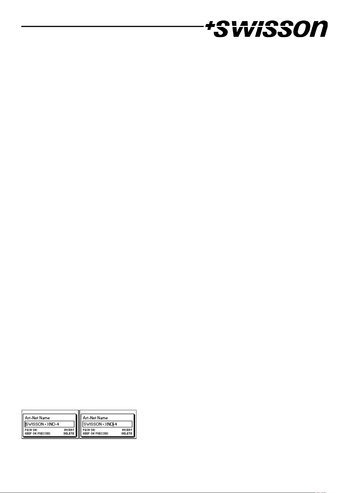
Name
The device name can be viewed and edited under Home > Menu > Art-Net > Name.
Deleting Text
To delete a text line or a part of it, position the cursor immediately to the left of the first character you want to have
deleted.
Page 15
15
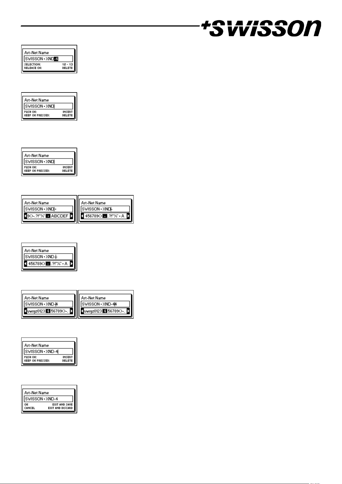
Then keep [OK] pressed and turn the encoder clockwise until all of the text that you wish to delete appears highlighted.
As you release the [OK] button, the highlighted text is removed.
Inserting or Appending Text
To append or insert text, move the cursor to the position where you want to add your text.
Then push the [OK] button and select a character to add.
Confirm your selection by pressing [OK].
Repeat the above steps for the remaining characters. Then, press [Cancel] to finish inserting characters.
Press [Cancel] again to quit the editor.
Press [OK] to store the changes or press [Cancel] to discard all changes.
Page 16
16
Short Name
The short name can be viewed and edited under Home > Menu > Art-Net > Short Name. Editing the short name is
done in the same way the name is edited.
Port Settings
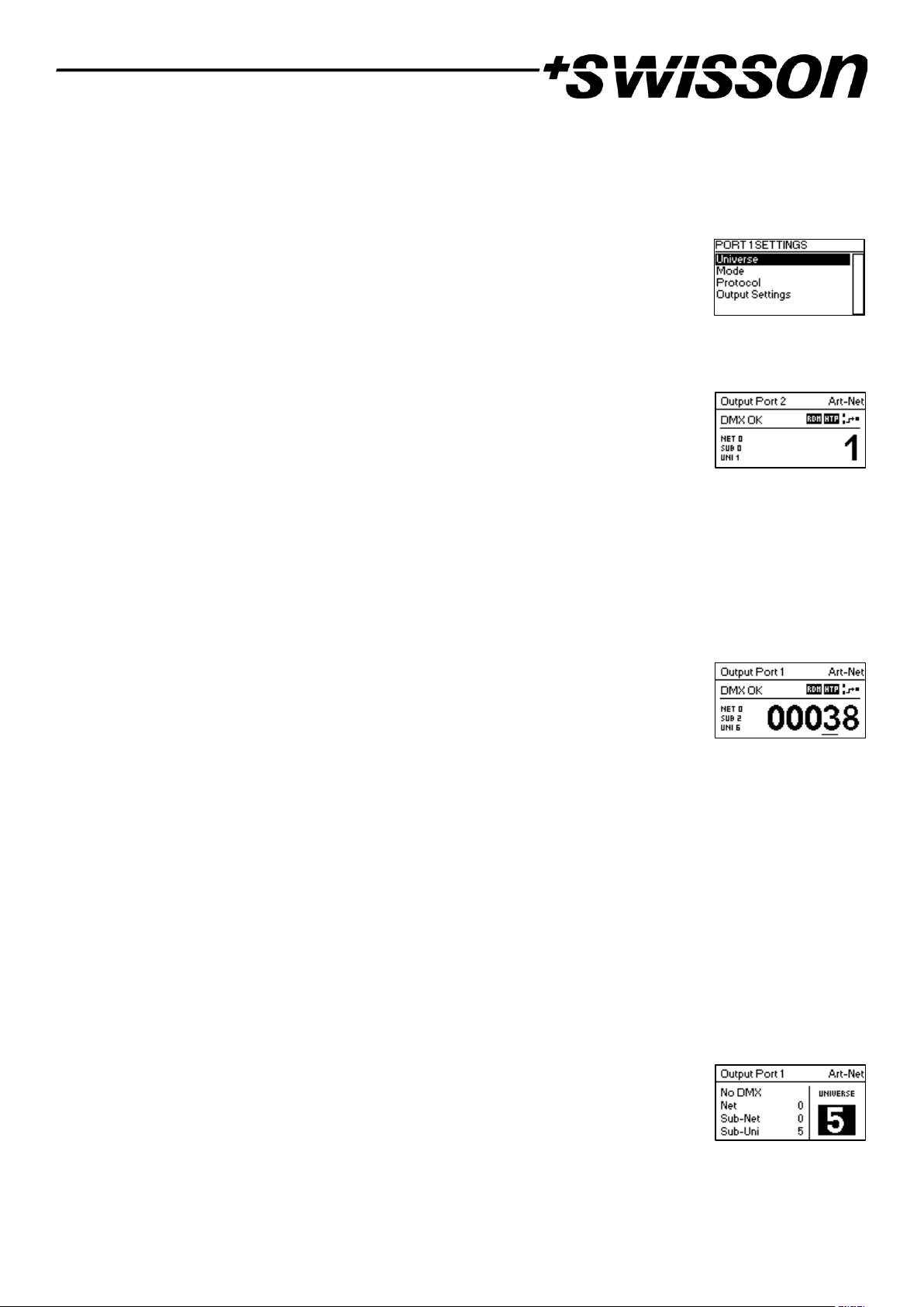
For each port, there is a settings menu under Home > Menu > Ports > Port [1-4]. E.g. the
menu for port 1 is under Home > Menu > Ports > Port 1. The port settings menu contains the
items described below. When opening this screen with a double tap to the port button
(button [1] – button [4], see page 7) this menu is shown as a reduced version with only the
options required for configuring the current mode.
Universe
To adjust the universe of port X, navigate to Home > Menu > Ports > Port X > Universe. This
screen can also be reached by pressing the corresponding port button once.
This screen provides essential information about the DMX port and allows for changing its
Art-Net or sACN universe. For more information about the indicators on this screen, see
section Port Screen.
Use the encoder wheel for changing the universe of the given port. Once the desired universe appears on the screen,
push OK to use this universe or press cancel to revert to the previously configured universe.
Art-Net (Version 4)
This section describes the universe configuration screen of ports that are in Art-Net mode while the Art-Net version
is set to Art-Net 4.
The port address is the large number on the bottom of the display. While it is being edited, a
slowly blinking cursor is shown below the currently editable digit. Use the encoder to
increase or decrease that digit. Push the port button corresponding to the port that is being
edited to change the digit that is currently editable. Firmware versions 1.01 and later also
display the Art-Net net, the Art-Net sub-net and the Art-Net universe part of the port address on the lower half of
the display near the left edge.
If an input port is configured for Art-Net 4, data is transmitted to the directed broadcast IP address (e.g.
2.255.255.255).
For more information about the addressing of Art-Net ports, see section Representations of Art-Net Port Addresses
in the appendix.
Art-Net (Version 3)
This section describes the screen for editing the universe of a port running in Art-Net mode when the Art-Net version
is set to Art-Net 3.
The screen looks the same on devices with a firmware older than version 1.01 if the corresponding port is in Art-Net
mode and independent universes are disabled. Consult page 14 for details about the independent universes feature.
Please note that while the universe (large number on the right-hand side of the display) is
being edited but has not yet been stored, its background lights up and the number is
displayed in its inverted colour about once every second. If that is the case and you just want
to see the configured universe number, simply press [Cancel].
On the left-hand side of the screen, the following information is displayed on three lines below the status label (see
section Status Indication on page 11): Art-Net net, Art-Net sub-net and Art-Net sub-uni.
Page 17
17
The Art-Net sub-uni is computed from the sub-net and the universe of a port as 16 x sub-net + universe. Some
controllers address the Art-Net universe as a single number in the range of 0 to 255. Sub-uni corresponds to that
number.
If an input port is configured for Art-Net v3, data is transmitted to the directed broadcast IP address (e.g.
2.255.255.255).
sACN
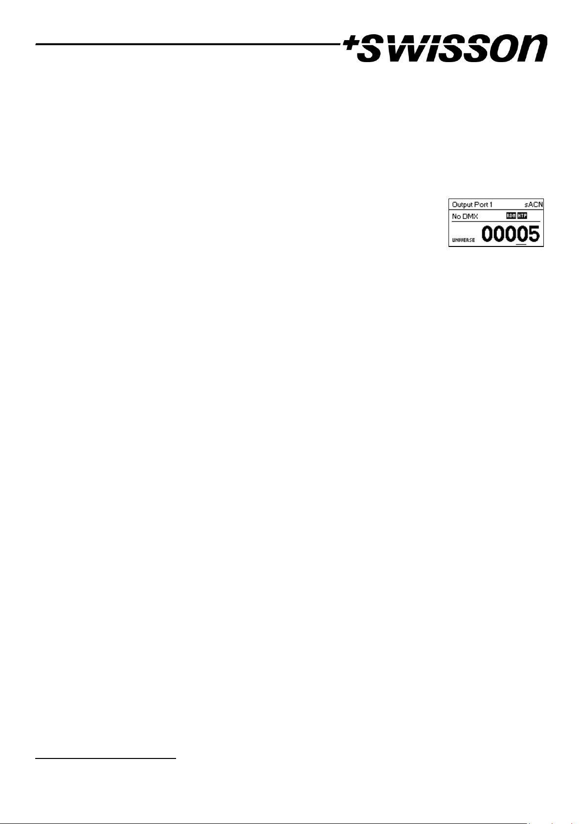
Ports that are running in sACN mode display the sACN universe number and status indicators.
The sACN universe number may be in the range of 1 – 63999. While the universe (large
number at the bottom) is being edited but has not yet been stored, a slowly blinking cursor
is shown below the currently editable digit. Use the encoder to increase or decrease that
digit. Push the port button corresponding to the port that is being edited to change the digit
that is currently editable.
If an input port is configured for sACN, data is transmitted to the sACN multicast IP address of the respective
universe (e.g. 239.255.0.1 for universe 1) or to a previously configured unicast IP address.
Mode
Under Mode, a selection list is presented to you with the following options:
• Output: The port outputs data received from the network.
• Input1: The port is configured as DMX input and sends data to the network.
• Off: The port is turned off.
A bullet point is shown next to the currently active setting. Use the encoder wheel to select the desired setting and
push [OK] to apply the setting.
When setting multiple inputs to the same universe, the node will output the data depending on the used protocol:
• Art-Net: Only one port will send data to the network, because Art-Net streams are identified by the IP
address.
• sACN: All inputs can send data to the network, because sACN identifies every stream with an own ID.
Protocol
Under Protocol, you can choose between the following two options:
• Art-Net: The port is using the Art-Net protocol for either input or output mode.
• sACN: The port is using the sACN protocol for either input or output mode.
A bullet point is shown next to the currently active setting. Use the encoder wheel to select the desired setting and
push [OK] to apply the setting.
Output Settings
DMX Output Mode
The DMX Output Mode menu allows for choosing the DMX timing. This menu item has been introduced with
firmware version 0.99. Currently the following choices are available:
• Max. Frame Rate (44 Hz)
• Relaxed (30 Hz)
When Max. Frame Rate is selected, the DMX output signal has the following properties:
1
Input mode only available on devices produced after 2017 (hardware rev. 1.0-b)
Page 18

18
• Refresh rate: Ca. 44 Hz when 512 channels are being sent, depending on the amount of RDM requests sent
from the controller and further reduced during RDM discovery.
• Break length: Ca. 180 µS.
• Mark after break: Ca. 40 µS.
The DMX Output Mode Relaxed has the following behavior:
• Refresh rate: Ca. 30 Hz when 512 channels are being sent, depending on the amount of RDM requests sent
from the controller and further reduced during RDM discovery.
• Break length: Ca. 300 µS.
• Mark after break: Ca. 80 µS.
• A small delay of about 20 µS is inserted between slots to reduce the update rate. This may reduce problems
such as flickering when legacy fixtures are in use.
Merge Mode
Under Merge Mode, a selection list is presented to you with the following options:
• HTP: Highest takes precedence. If for a given DMX channel data has been received from two sources, the
higher value is used.
• LTP: Latest takes precedence. If for a given DMX channel data has been received from two sources, LTP
merging uses the value of whichever source was the last to change the value it has sent for that given
channel.
• Off: Merging is disabled.
Merging is applied when two Art-Net or sACN controllers send data for the same port. If more than two
controllers send data for the same port, the following rules take effect:
• Art-Net: The first two appeared data streams are merged. All following ones are discarded.
• sACN: The first two streams with the same priority are merged. Further streams of the same or lower priority
are discarded. If a stream with higher priority appears, the lower priority ones will be discarded.
A bullet point is shown next to the currently active setting. Use the encoder wheel to select the desired setting and
push [OK], to apply the setting.
Failure Behaviour
Under Failure Behaviour, a selection list is presented to you with the following options:
• Off: The output will stop sending DMX, after no updates for the universe of the output have been received
for 10 seconds1.
• Hold Last Look: The output will continue to send the last look even if no updates are received.
A bullet point is shown next to the currently active setting. Use the encoder wheel to select the desired setting and
push [OK] to apply the setting.
Art-Net RDM
Under Art-Net RDM, RDM may be enabled or disabled for the output. Art-Net RDM can also be enabled for sACN
ports. XND-4 discovers a maximum of 250 devices per output port.
All the previously described settings can be changed via web interface on the Port Settings Page from page 27.
1
6 seconds for firmware version 0.93 and earlier
Page 19
19
Auto Universe Label
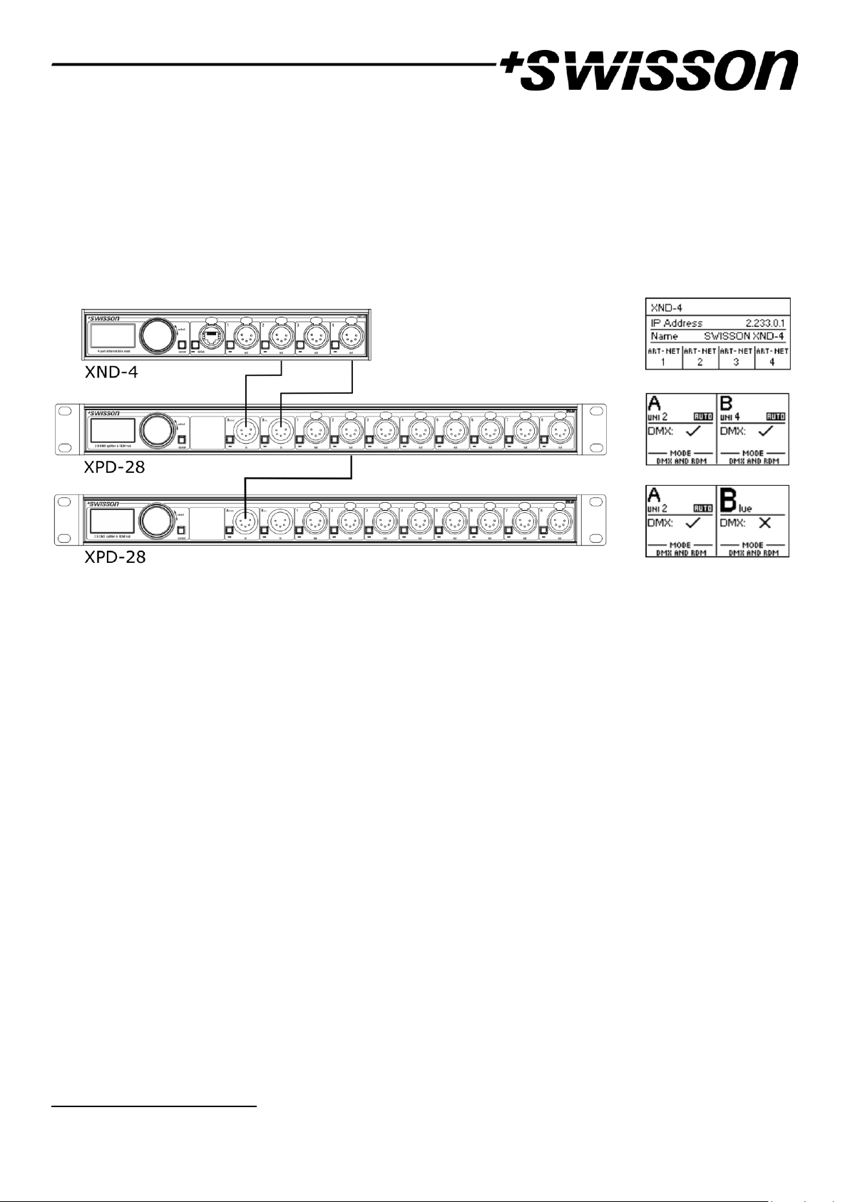
This menu is only shown when Art-Net RDM is enabled. Auto Universe Label is a functionality to automatically show
the universe number of an XND-4 port on the display of connected Swisson devices supporting this. When enabled,
the universe number is transmitted every two seconds with a small standard compliant RDM packet. Therefore, the
labels are only present on output ports with Art-Net RDM enabled. Auto Universe Label RDM packets are
transmitted as so called vendorcast messages and are ignored by every standard compliant DMX and RDM receiver
not manufactured by Swisson.
The following depiction shows an example setup using the Auto Universe Label feature.
Input Settings3
Transmit Mode
Under Transmit Mode, the transmission behaviour of Art-Net or sACN data can be configured with the following
settings:
• Broadcast/Multicast: DMX data applied to the input port is transmitted to the directed broadcast IP address
(multicast for sACN). Every reachable device in the same subnet can receive the data.
• Unicast: DMX data applied to the input port is transmitted to a unicast IP address set by the user. Only one
network device with matching IP address can receive the data.
Destination IP
This menu only appears when the Transmit Mode is set to Unicast. After opening the menu, an IP address edit
window is shown. This window allows for configuring a unicast destination IP address, similar to the IP address edit
windows in section Network Settings.
Local Forwarding
This menu only appears when the Transmit Mode is set to Unicast and allows to enable or disable the forwarding of
DMX data to the local ports of the node. If Transmit Mode is set to Broadcast/Multicast, the data is always
forwarded.
• Enabled: DMX data applied to an input port is forwarded to local DMX outputs of this node, if
universe and protocol of the output port is matching with the input port.
• Disabled: DMX data is only transmitted to the configured unicast IP address and not present on local
output ports of this node.
3
Available only on firmware version 1.04 and newer
Page 20

20
Factory Presets
Firmware Version 1.03
The Factory Presets menu entry of the main menu allows you to load one of the following factory defined presets on
devices with firmware version 1.03 or newer:
• Art-Net:
o Art-Net RDM is enabled on all ports.
o All ports are configured as outputs.
o Ports 1 – 4 are configured to consecutive Art-Net universes (port addresses). The user is asked to
choose a start universe.
o The user is prompted by a separate dialog to choose whether to adjust the network settings. If he
chooses to do so, the IP address is set to the primary Art-Net IP address and the netmask is set to
255.0.0.0.
• Art-Net, no RDM:
o Same as Art-Net, RDM disabled on all ports.
• sACN:
o All ports are configured as outputs.
o Network settings remain unchanged.
o Art-Net RDM is enabled.
o Ports 1 – 4 are configured to consecutive sACN universes. The user is asked to choose a start
universe.
• sACN, no RDM:
o Same as sACN, Art-Net RDM disabled on all ports.
• 1,2: Art-Net – 3,4: sACN:
o Art-Net RDM is enabled on all ports.
o All ports are configured as outputs.
o Ports 1 and 2 are configured to Art-Net.
o Ports 3 and 4 are configured to sACN.
o The ports are configured to consecutive universes (port addresses). The user is asked to choose a
start universe.
o The user is prompted by a separate dialog to choose whether to adjust the network settings. If he
chooses to do so, the IP address is set to the primary Art-Net IP address and the netmask is set to
255.0.0.0.
• Art-Net, Office Network:
o Same as Art-Net but network is configured via DHCP.
Firmware Version 1.00 and Older
The Factory Presets menu entry of the main menu allows you to load one of the following factory defined presets on
devices with firmware versions released prior to version 1.01 (version 1.00 or older):
• Art-Net:
o Loads default network settings (IP address set to primary Art-Net IP address).
o Art-Net RDM is enabled on all ports.
o Ports 1 – 4 are configured to Art-Net universes 0 – 3 (Art-Net sub-net: 0, Art-Net net: 0).
Page 21

21
• Art-Net, no RDM:
o Same as Art-Net, RDM disabled on all ports.
• sACN:
o Network is configured via DHCP.
o Art-Net RDM is enabled.
o Ports 1 – 4 are configured to sACN universes 1– 4
• 1,2: Art-Net – 3,4: sACN:
o Loads default network settings (IP address set to primary Art-Net IP address).
o Art-Net RDM is enabled on all ports. Note: affects port 1 and 2 only while port 3 and 4 are
configured to output data from sACN.
o Ports 1 and 2 are configured to Art-Net universe 0 and 1 (Art-Net sub-net: 0, Art-Net net: 0).
o Ports 3 and 4 are configured to sACN universe 3 and 4.
• Art-Net, Office Network:
o Same as Art-Net but network is configured via DHCP.
Loading any of the presets disables independent Art-Net universes (Independent Universes, page 14).
Device Settings and Information
Address Display Mode
Under Address Display Mode, a selection list is presented to you with the following options:
• Decimal: Art-Net net, Art-Net sub-net, Art-Net or sACN universe and Art-Net sub-uni are displayed as
decimal numbers.
• Hexadecimal: Art-Net net, Art-Net sub-net, Art-Net or sACN universe and Art-Net sub-uni are presented as
hexadecimal numbers with a trailing h (e.g. F3h).
A bullet point is shown next to the currently active setting. Use the encoder wheel to select the desired setting and
push [OK], to apply the setting.
Web Interface4
Under Web Interface, a selection list is presented to you with the following options:
• Enable: The web interface is enabled.
• Disable: The web interface is disabled.
A bullet point is shown next to the currently active setting. Use the encoder wheel to select the desired setting and
push [OK] to apply the setting. Changing this setting, requires a restart of the node. A popup will ask for
confirmation. Press [OK] to restart now or [Cancel] to abort.
This option of the device settings is only available as of firmware version 1.03. Further information can be found on
page 27.
Screen Saver
Under Screen Saver, a selection list is presented to you with the following options:
• Enable: Screen saver is enabled.
• Disable: Screen saver is disabled.
4
Web interface only available on devices produced after 2017 (hardware rev. 1.0-b)
Page 22
22
A bullet point is shown next to the currently active setting. Use the encoder wheel to select the desired setting and
push [OK] to apply the setting.
Please refer to the section Screen Saver on page 26 for more details about the behaviour of the screen saver.
Mute LEDs
Under Mute LEDs, a selection list is presented to you with the following options:
• Mute: All status indicator LEDs of the device remain dark regardless of the device’s status.
• Unmute: The status indicator LEDs behave as described under Status LEDs on page 25.
A bullet point is shown next to the currently active setting. Use the encoder wheel to select the desired setting and
push [OK] in order to apply the setting.
All previously listed device settings can be changed via the web interface on the
Device Settings Page as described on page 28.
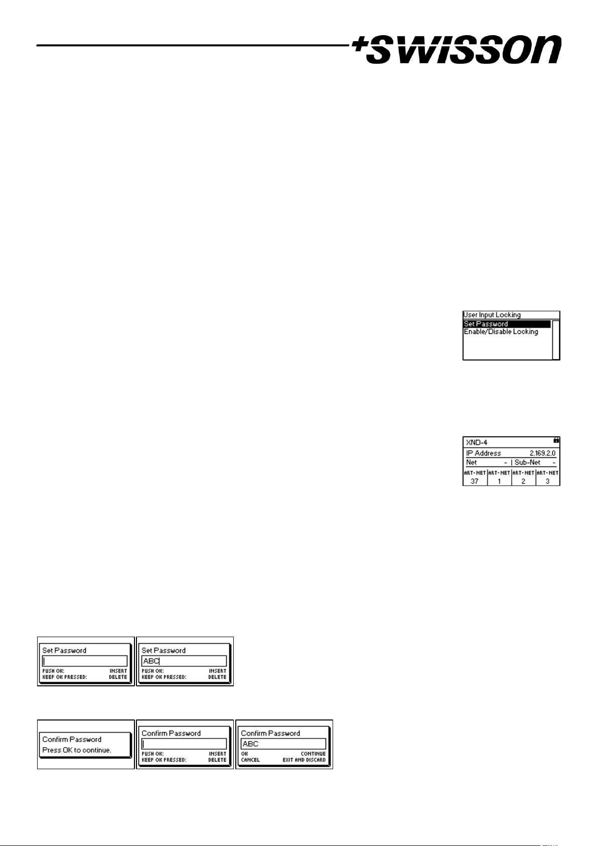
User Input Locking
The menu item User Input Locking allows you to lock your device with a password to protect
your device from unauthorized or accidental manipulation. Alternatively, the device may
also be locked without a password in order to just prevent accidental manipulation. For
details see Simple Locking on page 23.
When the device is locked, the user will only be able to see the Home Screen (see page 10) and the Ethernet Port
Status Information (see page 25). Since the menu is unavailable while the device is locked, the Ethernet Port
Status Information is only accessible via the Ethernet port button [E].
When pressing the [OK] button from the Home Screen of a locked device, it will prompt for
the password if the device was password locked. If the password is then entered correctly,
the device becomes unlocked and the main menu is displayed.
Otherwise, if simple locking was used, a dialog will be shown asking the user to press [Cancel] three times within
three seconds after pressing [OK] while the Home Screen is shown, and the device was locked. If the user does so,
the device becomes unlocked.
A padlock symbol in the top right corner of the Home Screen indicates that the user input is currently locked.
Before a device can be locked by password, a password must be set, and locking must be enabled.
Set Password
Choose the menu entry Settings > User Input Locking > Set Password to set a password. A dialog will show up that
prompts for a password. Password editing works just like editing the device name, as detailed on page 14.
Once the password has been entered, XND-4 will ask you to enter the password a second time.
If the two entered texts match, the password is set.
Page 23
23
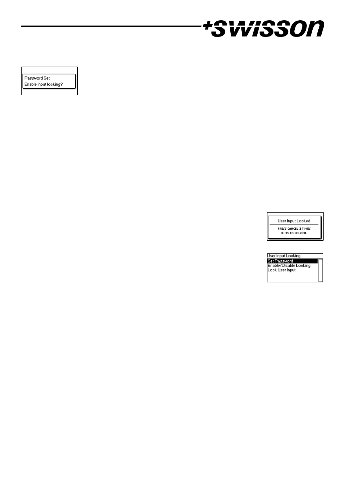
Finally, after the password was successfully stored, the user will be asked whether he wants to enable password
locking, if it is not already enabled.
By pressing [OK], password locking is enabled. Pressing [Cancel] closes the dialog and keeps password locking
disabled, but the password is set anyway.
To change the password, simply open the Set Password dialog again. It is not required to enter the current password
before changing it.
Enable/Disable Locking
The menu entry Settings > User Input Locking > Enable/Disable Locking lets the user choose whether password
locking is disabled or enabled.
Password Locking
If the user requests to enable password locking and a password has already been set, the user will be asked to enter
the password before password locking is enabled. If the user requests to enable password locking when no password
has been set up, the user will be prompted to enter and confirm a password, before password locking is enabled.
Simple Locking
Simple locking can be enabled whether a password has been set or not. When simple locking
is used, the user will be asked to press [Cancel] three times within 3 seconds when
attempting to unlock the device by pressing the [OK] button from the home screen.
Lock User Input
Once password locking has been enabled, the additional menu item Lock User Input will
appear on the top level of the menu and under Home > Menu > Settings > User Input
Locking. If the user activates this menu item, he will be asked whether the device should be
locked. [OK] will lock the device, [Cancel] will keep it unlocked.
The device will also be locked when the screen saver becomes active or after a power cycle if password locking has
been enabled.
Device Information
The following information about the device is available under Home > Menu > Device Settings > Device Information.
Model
The device model is reported as “XND-4” for all variants of the XND-4.
Boot Software
The full version number of the boot software.
Firmware
The full version number of the firmware.
Hardware
The hardware revision.
MAC Address
The MAC address of the node’s Ethernet interface.
Page 24

24
UIDs
The RDM UIDs (unique identifiers) of the four output ports. These are numbers that unambiguously identify any
RDM device. Since each output port may act as an RDM controller, each output port has assigned its own RDM UID.
Restore Default Settings
The default settings can be restored under Home > Menu > Restore Default Settings. In this menu, you will be asked
whether you want to continue restoring all settings. Push [OK] to confirm or [Cancel] to abort.
The default settings can also be restored from the
Device Settings Page of the web interface as described on page 28.
This function will restore all settings to the defaults:
• Name: SWISSON XND-4
• Short name: XND-4
• Art-Net net: 0
• Art-Net sub-net: 0
• Art-Net RDM: Disabled on all output ports1
• Auto universe label: Enabled2
• Independent universes: Disabled3
• Art-Net version: Art-Net 44
• All outputs enabled
• DMX output mode (all ports): Relaxed5
• Art-Net universe output 1-4: 0-3
• Failure behaviour (all outputs): Hold last look
• Merge mode (all outputs): HTP
• Input transmit mode: Broadcast/multicast
• Input destination IP: 127.0.0.1
• Input local forwarding: Enabled
• IP address: 2.X.Y.Z (primary Art-Net IP address)
• Netmask: 255.0.0.0
• Address display mode: Decimal
• LEDs: Unmuted
• Screen saver: Disabled
• User input locking: Disabled, password not set
• Web interface: Enabled6
1
For firmware versions 0.99 and earlier, RDM enabled per default.
2
Available on firmware version 1.04 and newer only
3
Available on firmware version 1.00 and older
4
Available on firmware version 1.01 and newer only
5
Firmware versions 0.99 and 1.00: Max. frame rate
6
Available on firmware version 1.03 and newer only
Page 25

25
Ethernet Port Status Information
This screen is reached by pressing the Ethernet port button [E], which is located right next to
the Ethernet port on most models. See Device Overview on page 7 for more precise
information about the location of this button.
This screen shows the following information about the status of the Ethernet port on four lines:
• The first line below the title shows whether the link is up or down and what the current connection speed is
(10 Mb/s or 100 Mb/s).
• The next line informs whether the link is full or half duplex if a link is established.
• The last two lines display the currently configured IP address and the currently configured netmask.
Status LEDs
All LEDs can be muted, in which case they stay dark independently of the device’s status. The information below
applies when the LEDs are not muted (unmuted). Please refer to Mute LEDs on page 22 for more information about
muting and unmuting the LEDs.
Selected Port
When a port is selected, the port’s status LED flashes in white for 0.1 seconds once every 0.2 seconds. The DMX ports
and the Ethernet port can be selected using the respective port push button. Further, the DMX ports can also be
selected via the menu (Home > Menu > Outputs > Output [1-4] > Universe).
Not Selected DMX Port
If a DMX port is not selected, the port’s status LED provides the following information. It shows the port status for at
least 0.7 seconds every second using the following colour coding:
• Output port:
o Red: Not sending DMX data, but the port is enabled.
o Yellow: Sending last look, but did not receive an update for at least 10 seconds1.
o Green: Sending DMX data, receiving updates.
o Black: Port is disabled / turned off.
• Input port
o Blue flashing: No DMX signal detected.
o Blue static: DMX signal is present and valid.
o Red: DMX signal error.
• Disabled port:
o Black: Port is disabled / turned off.
The LED lights up white for 0.3 seconds every second if the node is set identified.
Ethernet Port (Not Selected)
The status LED lights up for 0.3 seconds every second if the node is set identified.
Next to the status LED, there is also a link LED, which lights up in green if an Ethernet link has been established.
Traffic is indicated by short interruptions.
1
6 seconds with firmware versions 0.93 and earlier
Page 26

26
Identify
The XND-4 can help the user to locate the device under certain conditions through the identify process. The node
can be set in an identified state, by means of communication, like Art-Net, RDM or the web interface. In the case of
the XND-4 the identified device will light up all port status LEDs white, for 0.3 seconds every second, for as long as
the device is set identified.
Screen Saver
The OLED display will automatically turn itself off when no user input is received for 40 seconds in order to improve
the durability of the product, if the screen saver is enabled. Once the display is turned off, it can be turned on again
by pushing any button or by turning the encoder wheel by one unit in any direction.
The screen saver can be enabled or disabled under Home > Menu > Device Settings > Screen Saver, as described under
Screen Saver on page 21.
Firmware Updates
Firmware updates will be provided on the product page on the Swisson website. For updating the firmware, a PC
with Windows (Vista or later) and a USB A to B cable (USB printer cable) is required. Please refer to the separate
documentation also provided on the product web page for details about the process of updating the product’s
firmware.
Alternatively, firmware updates can be done via web interface on the Firmware Update Page as described on page
28.
Page 27
27
Web Interface
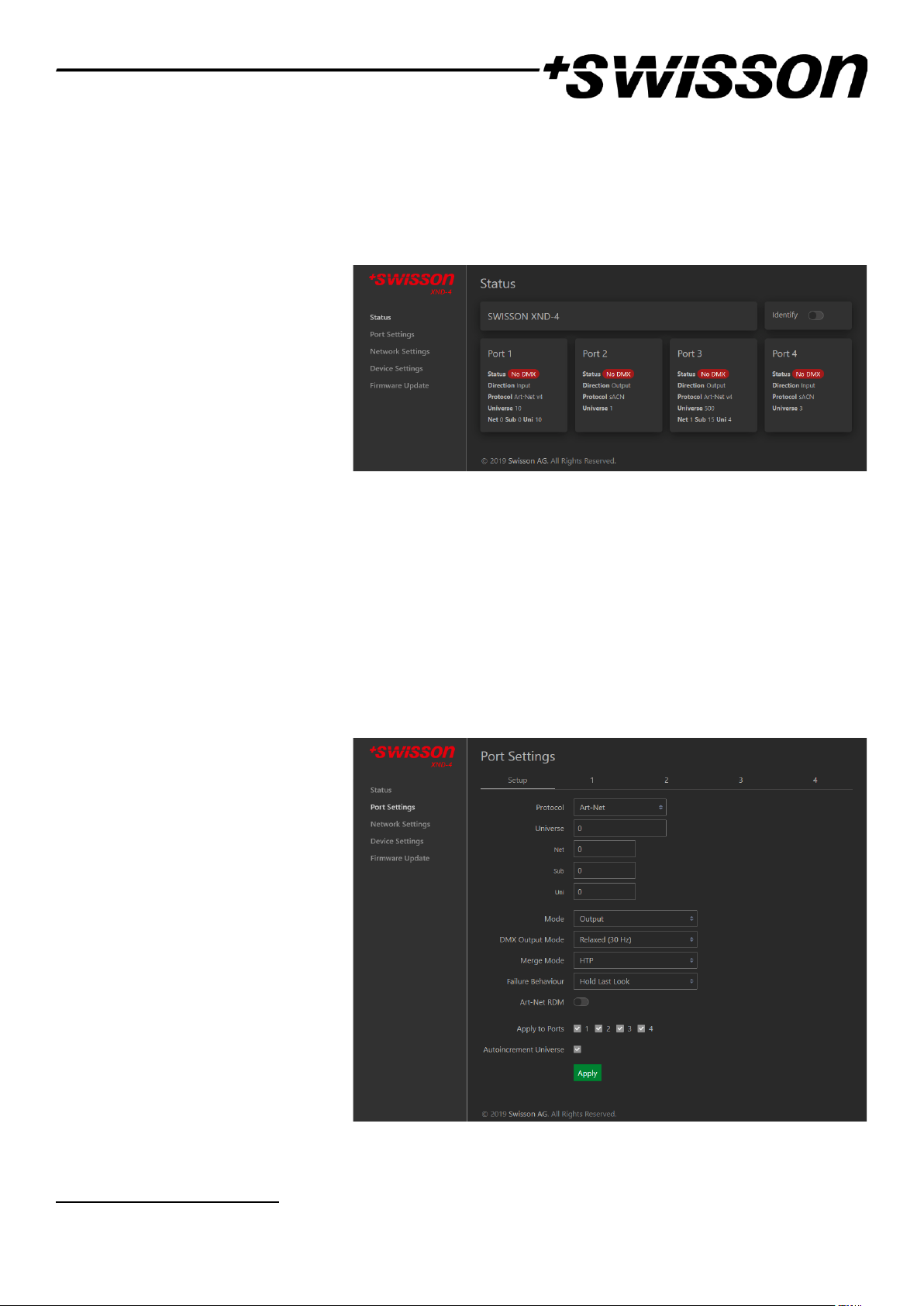
As of firmware version 1.03 the XND-4 allows the use of a web interface1 hosted by the device. Through this
interface the status may be observed, settings can be adjusted, and firmware updates can be carried out. The web
interface is accessed by typing the devices configured IP address in a web browser of a computer, that is connected
to the same network as the XND-4.
Status Page
The status page is the first to welcome
the user after accessing the web
interface. It lets the user get an
overview over every individual port’s
status and configuration at a quick
glance. In addition to the overview a
toggle switch can be enabled to set the
device identified.
The ports can display five different status messages, like the ones described on page 11:
• OK: The port is receiving/transmitting successfully.
• No Update: Not receiving any updates on this universe for the last 10 seconds.
• Off: The port is currently disabled through settings made by the user.
• No DMX: The port is not receiving/transmitting any DMX.
• Error: The port is producing errors and requires user intervention.
Port Settings Page
On the port settings page each port can
be configured individually, or changes
can be applied to multiple ports at once.
To configure the ports separately, select
the number in the top menu first, after
which changes can be made to the
settings. Once the changes are made,
they can be sent to the device by
pressing the apply button.
More information on the port settings
can be found on page 16.
When setting up multiple ports at the
same time under the Setup tab, the user
has the option to select which ports the
changes should be applied to and
choose to autoincrement the universe number along the ports that are being configured.
1
Web interface only available on devices produced after 2017 (hardware rev. 1.0-b)
Page 28
28
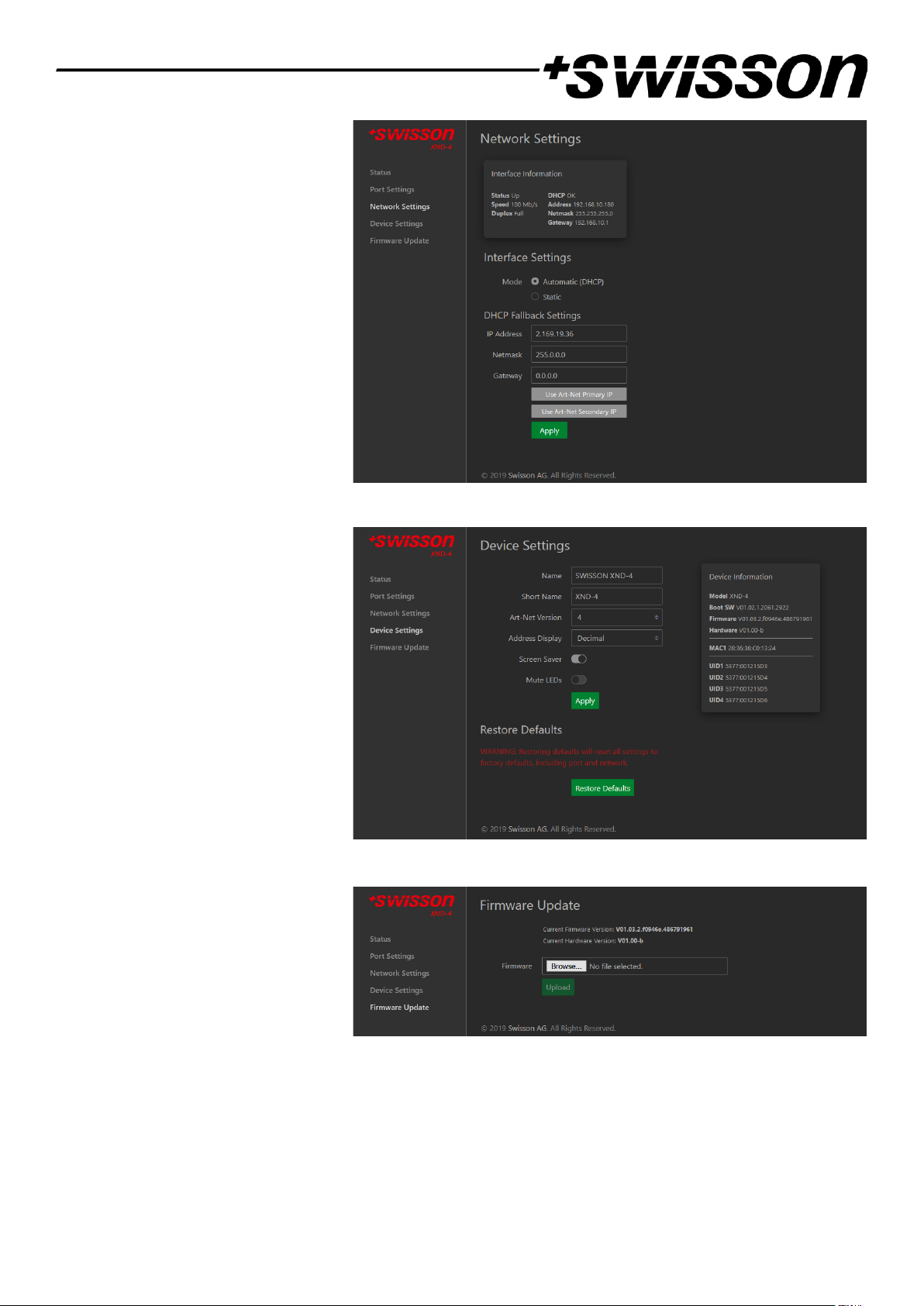
Network Settings Page
The network settings page enables the
user to change network settings and see
relevant information concerning the
Ethernet port status.
For a detailed description of the
network settings, please consult page 12
where they are described in detail.
Attention: Changes to the network
settings could result in the device not
being accessible via network! Use with
caution!
Device Settings Page
This page allows the user to view and
make changes to any relevant device
information. Furthermore, the factory
defaults can be restored from here.
A detailed description of the device
settings can be found on page 21.
Firmware Update Page
From this page firmware updates can be
performed. To do so, simply select the
desired firmware file and then upload it.
Additionally, this page informs you
about the currently loaded firmware and
the hardware version.
For more information on firmware updates, see page 26.
Browser Compatibility
The web interface is compatible with most current web browsers. For a detailed list of supported browser versions,
please consult the appendix.
Page 29
29
Technical Data
XND-4R
XND-4B
XND-4D
Page 30

30
Ambient temperature .................................................................. -30°C…55°C (-22°F…131°F)
AC power ...................................................................................... 100 - 240 V nominal, 50/60 Hz
DC power (XND-4D) ..................................................................... 10 – 48 V DC
Typical power consumption ......................................................... 7 W
Typical power consumption (XND-4D) ......................................... 4 W
Ethernet ....................................................................................... 10BASE-T / 100BASE-TX, auto negotiating, auto
MDI-X
Network protocols ....................................................................... Art-Net 1 - 4, sACN (ANSI E1.31), sACN draft version
(v0.2)
DMX .............................................................................................. ANSI E1.11
RDM ............................................................................................. ANSI E1.20
Electrical standard signal ports .................................................... EIA-485
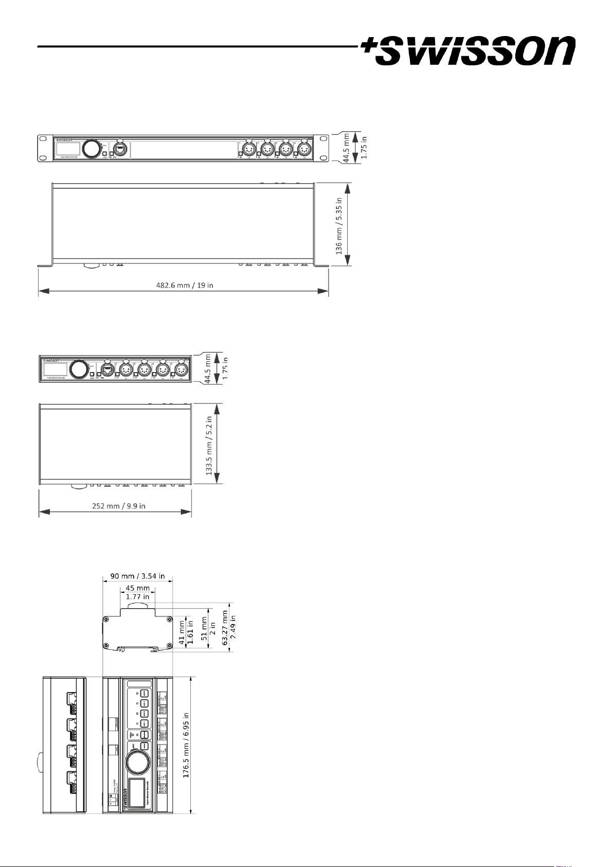
Dimensions Rack Mountable Models
Depth............................................................................................ 136 mm (5.35 in)
Width ........................................................................................... 482.6 mm (19 in)
Height ........................................................................................... 44.5 mm (1.75 in)
Weight .......................................................................................... 1.6 kg (3.53 lb.)
Dimensions Box Models
Depth............................................................................................ 133.5 mm (5.2 in)
Width ........................................................................................... 252 mm (9.9 in)
Height ........................................................................................... 44.5 mm (1.75 in)
Weight .......................................................................................... 1.1 kg (2.43 lb.)
Dimensions DIN Rail Model
Depth............................................................................................ 63.27 mm (2.49 in)
Width ........................................................................................... 176.5 mm (6.95 in)
Height ........................................................................................... 90 mm (3.54 in)
Weight .......................................................................................... 670 g (1.47 lb.)
Page 31

31
Ordering Information
Standard Versions, Boxes
10 48 10 XND-4B3 4-port Ethernet DMX node, box version, 3-pin XLRs
10 48 11 XND-4B5 4-port Ethernet DMX node, box version, 5-pin XLRs
10 48 12 XND-4B8 4-port Ethernet DMX node, box version, RJ45 etherCON
Standard Versions, Rack Mountable
10 48 20 XND-4R3 4-port Ethernet DMX node, rack mountable, 3-pin XLRs
10 48 21 XND-4R5 4-port Ethernet DMX node, rack mountable, 5-pin XLRs
10 48 22 XND-4R8 4-port Ethernet DMX node, rack mountable, RJ45 etherCON
Standard Version, DIN Rail Model
20 16 10 XND-4D 4-port Ethernet DMX node, DIN rail, RJ45 & terminal
Credits
LwIP
This product includes parts of lwIP which is licenced under the BSD licence:
Copyright (c) 2001-2004 Swedish Institute of Computer Science.
All rights reserved.
Redistribution and use in source and binary forms, with or without modification, are permitted provided that the following conditions are met:
1. Redistributions of source code must retain the above copyright notice, this list of conditions and the following disclaimer.
2. Redistributions in binary form must reproduce the above copyright notice, this list of conditions and the following disclaimer in the documentation and/or other materials provided with the distribution.
3. The name of the author may not be used to endorse or promote products derived from this software without specific prior written permission.
THIS SOFTWARE IS PROVIDED BY THE AUTHOR ``AS IS AND ANY EXPRESS OR IMPLIED WARRANTIES, INCLUDING, BUT NOT LIMITED TO, THE IMPLIED WARRANTIES OF MERCHANTABILITY AND FITNESS FOR A
PARTICULAR PURPOSE ARE DISCLAIMED. IN NO EVENT SHALL THE AUTHOR BE LIABLE FOR ANY DIRECT, INDIRECT, INCIDENTAL, SPECIAL, EXEMPLARY, OR CONSEQUENTIAL DAMAGES (INCLUDING, BUT NOT LIMITED
TO, PROCUREMENT OF SUBSTITUTE GOODS OR SERVICES; LOSS OF USE, DATA, OR PROFITS; OR BUSINESS INTERRUPTION) HOWEVER CAUSED AND ON ANY THEORY OF LIABILITY, WHETHER IN CONTRACT, STRICT
LIABILITY, OR TORT (INCLUDING NEGLIGENCE OR OTHERWISE) ARISING IN ANY WAY OUT OF THE USE OF THIS SOFTWARE, EVEN IF ADVISED OF THE POSSIBILITY OF SUCH DAMAGE.
Art-Net
Art-Net™ Designed by and Copyright Artistic Licence Holdings Ltd
Page 32
32
Appendix
Representations of Art-Net Port Addresses
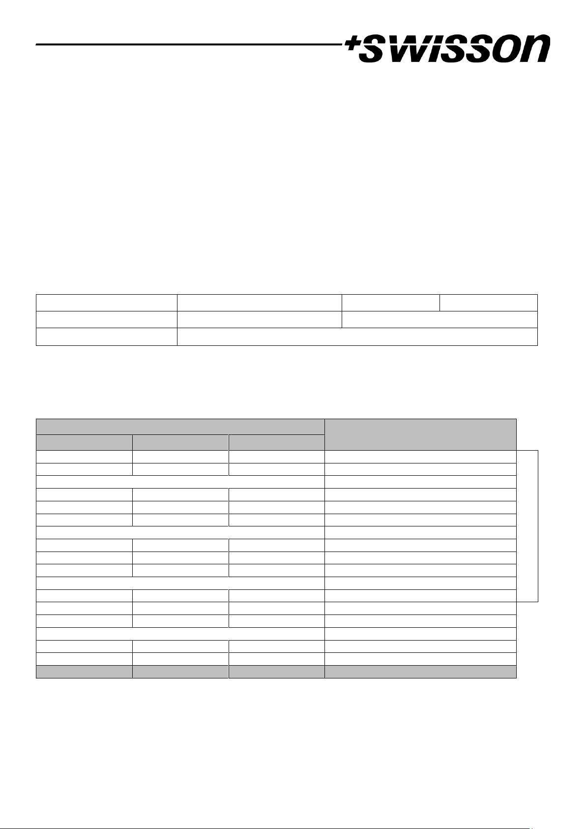
According to the Art-Net 3 specification, the address of an Art-Net port consists of three parts: The Art-Net net, subnet and universe number. The Art-Net universe and sub-net number both have a value between 0 and 15 (4 bits).
Many controllers combine these values to the sub-uni number, resulting in a value between 0 and 255 (8 bits), with
the sub-net part occupying the more significant digits. Thus, the sub-uni can be calculated with the formula 16 x subnet + universe = sub-uni.
The Art-Net net number was added in Art-Net 3 and has a value between 0 and 127 (7 bits). So, when working with
controllers using Art-Net I or Art-Net II, the Art-Net net must be set to 0.
The Art-Net net, sub-net and universe can be combined to a 15-bit port address with values from 0 to 32767, as
shown below.
Bit Digit
14
13
12
11
10 9 8 7 6 5 4 3 2 1 0
Subdivided Representation
Net (0 - 127)
Sub-Net (0 - 15)
Universe (0 - 15)
Alternative Representation
Net (0-127)
Sub-Uni (0 – 255)
15-bit Port Address Rep.
(0 – 32767)
For the instances where the Art-Net net number is 0, the 15-bit port address is equivalent to the sub-uni. The table
below gives an overview of the entire Art-Net 3 address space and how it is converted to a 15-bit port address.
Art-Net Address
15-bit Port Address
Net (0 - 127)
Sub-Net (0 - 15)
Universe (0 - 15)
0 0 0
0
Art-Net II addresses
0 0 1
1
…
…
0 0 15
15
0 1 0
16
0 1 1
17 … …
0 1 15
31
0 2 0
32
0 2 1
33 … …
0
15
15
255
1 0 0
256
1 0 1
257
….
….
127
15
14
32766
127
15
15
32767
z y x
𝐳 ∗ 𝟐𝟓𝟔 + 𝐲 ∗ 𝟏𝟔 + 𝐱
Page 33
33
Web Interface Compatible Browsers
The web interface was tested with following browsers.
Browser:
Version:
Chrome
80.0.3987.132
Firefox
73.0.1
Safari
13.1
Opera
67.0.3575.53
Edge
44.17763.831.0
Internet Explorer
11.1039.17763.0
Page 34

No part of this documentation may be reproduced or transmitted in any form or by any means, electronic or
mechanical, including photocopying and recording, without the prior written permission of Swisson AG.
The information in this documentation is supplied without warranty of any kind, either directly or indirectly, and is
subject to change without prior written notice.
Swisson, its employees or appointed representatives will not be responsible for any damages to software, hardware,
or data, arising as a direct or indirect result of the product(s) mentioned herein.
22.09.2020
SWISSON AG SWISSON of AMERICA Corp.
Fabrikstrasse 21 2419 East Harbor Blvd.#3
CH-3250 Lyss Ventura, CA 93001
Switzerland U.S.A.
E-Mail: [email protected]
 Loading...