

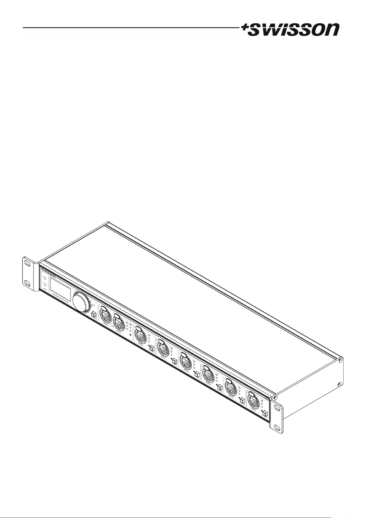
XES-2T6
Premanaged Gigabit Ethernet Switch
User Manual

2
UM_XES-2T6-D0-LEN-V01-00-DRAFT.DOCX 2018-11-28

3
Index
Index .................................................................................................................................................................................. 3
Introduction ...................................................................................................................................................................... 4
Unpacking ......................................................................................................................................................................... 5
Safety Information ............................................................................................................................................................ 5
Device Overview ............................................................................................................................................................... 7
Settings and Menu .......................................................................................................................................................... 10
Screen Saver .................................................................................................................................................................... 15
Firmware Updates ........................................................................................................................................................... 15
Technical Data ................................................................................................................................................................. 16
Ordering Information ...................................................................................................................................................... 17

4
Introduction
The XES-2T6 is a six plus two port Gigabit Ethernet switch with two ports being aggregated to a high throughput,
redundant trunk link. The six other ports are individually assignable to groups (IEEE 802.1Q VLANs) that may participate
in completely independent networks that do not interfere with each other. Thanks to the graphic OLED display, the
encoder knob and a push button for each of the six configurable ports, the switch is intuitive to setup and the configuration is done in next to no time.
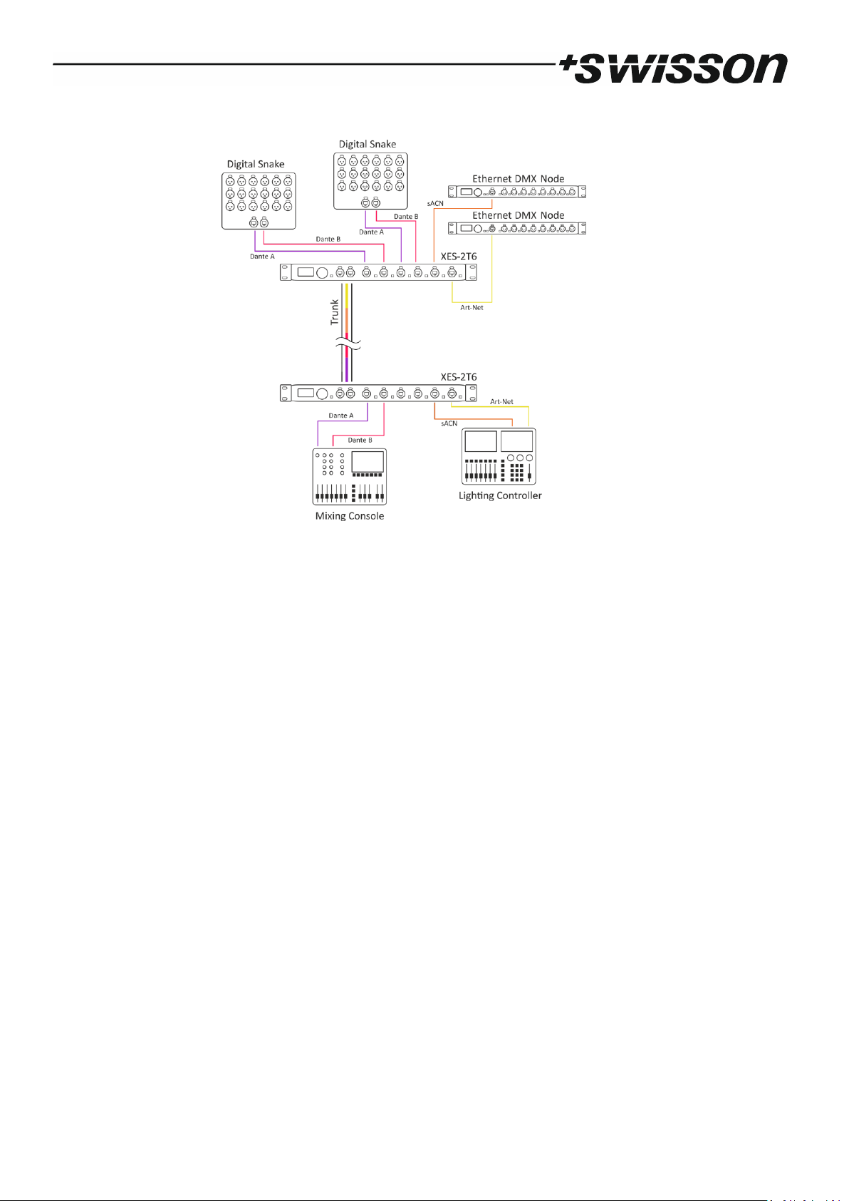
The grouping and the redundant fast backbone link make the XES-2T6 an ideal solution for interconnecting the stage
with the FOH for instance.
As a layer 2 switch, the XES-2T6 is generally unaware of the application and therefore it works well with any protocol
that operates on top of TCP/IP and with many Ethernet1 based protocols. However, special precautions have been
taken to ensure that the XES-2T6 works perfectly with Art-Net, sACN and Dante. The Art-Net specification for example
expects the controller to only send data every few seconds or when an update is available. A typical switch might put
itself into sleep mode when no traffic is observed, not so the XES-2T6; it stays ready to forward data anytime without
delay.
With the increased acceptance of TCP/IP and Ethernet based protocols, the proper operation of the network and its
components has become critical for many shows. In stage lighting for example, the control data transmitted from a
light controller will often be passed through at least one switch before it reaches any actual fixture. Therefore, it is
crucial to professionally plan, configure and install the network for any show or venue. As a measure to further lower
the chances of network outages, the XES-2T6 comes equipped with two separate switch mode PSUs that can be powered from two different mains supplies.
Applications
• Concert lighting
• Live events
• Multimedia shows
• Theaters
• TV studios
• Theme parks
• Architectural lighting
• Touring / festivals
1
As a layer 2 switch, the XES-2T6 works with all protocols that operate on top of the Ethernet protocol. However, there are some
protocols which are based on the lower layers of Ethernet but are not fully Ethernet compliant. Such protocols may not work with
Ethernet switches. Examples of such protocols are: AES50, SuperMAC, HyperMAC and Aviom A-Net.
5
Typical Application
Unpacking
The XES-2T6 is packaged in a cardboard box including the following items:
• The device.
• This user manual.
Safety Information
It is essential that you read and understand this manual before operating the device and that you
follow the instructions given below closely when you set up, connect and use the XES-2T6. Do not
use the device in any way or for any purpose not described in this user manual.
This product is approved for professional use only; it is not intended for household usage. Pay
attention to all warnings given in this manual and use this device only in accordance with applicable laws and regulations.
Safety Precautions
• Disconnect the device from all AC power supplies before removing any cover or part, in-
cluding fuses, even when not in use.
• Ensure that the device is electrically connected to ground (earth).
• Use only sources of AC power supply that comply with local building and electrical regula-
tions and which have both overload and ground fault (earth fault) protection.
• Before using the device, check that the power distribution equipment and cables are in
perfect condition and rated for the electrical current consumed by all connected devices.

6
• Isolate the device from power supply immediately if the power cable or the power plugs
are in any way damaged, defective or wet, or if they show signs of overheating.
• Do not expose the device to rain or moisture.
• Do not operate the device if any cover or component is missing, damaged or deformed.
• Refer any service operation not described in this manual to Swisson.
• Provide unrestricted airflow around the device.
• Do not operate the device if the ambient temperature exceeds 55°C (131°F).
• Do not modify the device in any way not described in this manual or install other than gen-
uine Swisson parts.
• Do not attempt to bypass any fuse. Replace any defective fuse with one of the specified
type and rating only.
• When suspending the device, ensure that the supporting structure and all hardware used
can hold at least 10 times the weight of all devices suspended together.
• When suspending the device, install a secondary attachment such as a safety cable that is
approved by an official body, e.g. TÜV (German Technical Monitoring Association), for the
total weight it secures. The safety cable must comply with EN 60598-2-17 section 17.6.6
and be capable of bearing a static suspended load of 10 times the weight of the device.
• Make sure that any external cover and rigging hardware is securely fastened.
• Provide an adequate clearance underneath the work area and a stable platform whenever
installing, servicing or moving an overhead device.
• Do not use the device in areas where it is exposed to direct sunlight.
• Do not use the device in areas that are considered to be “highly inflammable”.
7
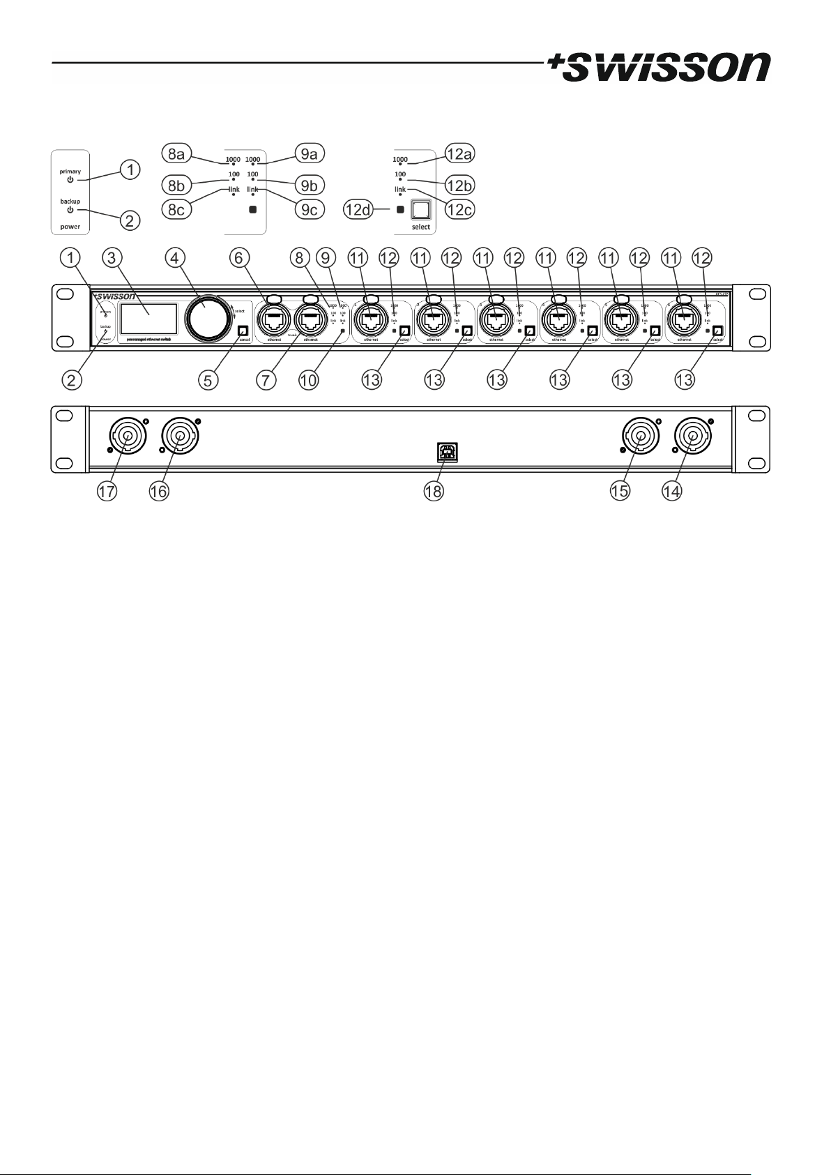
Device Overview
1. Status LED for primary PSU.
2. Status LED for backup PSU.
3. OLED display.
4. Encoder knob.
5. Cancel button.
6. Neutrik etherCON Cat 5e RJ45 connector for Gigabit Ethernet trunk port 1.
7. Neutrik etherCON Cat 5e RJ45 connector for Gigabit Ethernet trunk port 2.
8. Connection status LEDs for trunk port 1.
a. 1000 Mbit/s activity LED.
b. 100 Mbit/s activity LED.
c. Link LED.
9. Connection status LEDs for trunk port 2.
a. 1000 Mbit/s activity LED.
b. 100 Mbit/s activity LED.
c. Link LED.
10. Group colour LED for aggregated trunk ports.
11. 6 x Neutrik etherCON Cat 5e RJ45 connector for Gigabit Ethernet.
12. Connection status LEDs for Ethernet ports.
a. 1000 Mbit/s activity LED.
b. 100 Mbit/s activity LED.
c. Link LED.
d. Group colour LED.
13. Port selection button.
14. Neutrik powerCON output for looping through primary PSU mains.

8
15. Neutrik powerCON input for primary PSU mains.
16. Neutrik powerCON output for looping through backup PSU mains.
17. Neutrik powerCON input for backup PSU mains.
18. USB type B connector for firmware updates.
Mains Connections
The user must supply suitable power cables. He may then either hard-wire the power cables to the building’s electrical
installation, providing an easily accessible power on/off switch close to the device, or install on the power cables a
grounding-type (earthed) mains plug that is suitable for the local power outlets, following the power plug manufacturer’s instructions.
It is possible, but not required to use two different mains sources. However, it is important to notice that the earth
conductors of the two mains supplies will be short-circuited by connecting the two mains supplies to the same XES2T6. Consult a qualified electrician, if you have any doubts about the proper installation.
A blue Neutrik powerCON NAC3FCA cable mount connector must be used to supply power at the XES-2T6’s power
input socket.
Warning! For protection against dangerous electrical shocks, the device must be grounded (earthed). The
local AC power source must be supplied with both overload and ground-fault (earth fault) protection.
Important! Only attach or remove a Neutrik powerCON connector while it is connected to the mains in
case of an emergency, as doing so may cause arcing at the terminals that will damage the connectors.
Backup Power Supply
The device has two built-in PSUs. If both PSUs are connected to the mains, the primary PSU will supply the device while
the backup PSU stays in standby mode. Should the primary PSU fail, the backup PSU will immediately start to power
the device without an interruption.
Power Outlets
Warning! The current load of each of the AC mains power outlets of the XES-2T6 must not exceed 19.8
amperes.
• A power cable that meets the requirements specified in the safety instructions section of this manual must be used
to connect the XES-2T6 to AC mains power and to connect other devices to the power outlets.
• A light-grey Neutrik powerCON NAC3FCB cable-mount connector must be used to draw AC mains power from the
XES-2T6’s power outlet.
• No matter what the AC mains power voltage is, the current drawn by all the devices that draw AC mains power from
one of the power outlets of an XES-2T6 must not exceed a total of 19.8 amperes. That is 19.8 amperes for the primary
PSU mains loop through output and another 19.8 amperes that may be drawn from the backup PSU mains loop
through output.
Network Connectors and Cables
All network connectors are Neutrik etherCON Cat 5e RJ45 connectors. These connectors may be used with a standard
RJ45 plug. For a better fixation, you may use a cable with a Neutrik etherCON plug. For Gigabit Ethernet (1000BASE-T)
operation, Cat 5e (or better) cables are required. 100 Mbit/s (100BASE-TX) requires at least Cat 5 cables. For 10 Mbit/s
(10BASE-T) Cat 3 cables are sufficient. The maximum allowable cable length is 100 m (328 feet).

9
Status LEDs
The XES-2T6 has three status LEDs (8a-c, 9a-c, 12a-c) for each of the network ports plus a group colour LED for each of
the numbered Ethernet ports (12d) and a group colour LED for the aggregated trunk ports (10).
Further, there is also a status LED for each of the power supplies. The LED for the primary PSU (1) and the LED for the
backup PSU (2) indicate whether the respective PSU is powered from the mains and functioning.
The link LEDs (8c, 9c, 12c) are lit when the respective network port has established a network connection. The 100
Mbit/s activity LEDs (8b, 9b, 12b) indicate whether the corresponding port is working at 100 Mbit/s. When a 100 Mbit/s
connection has been established, these LEDs also show the activity of the respective ports. The more activity is present
at a port, the more frequently the corresponding LED will turn off for an instant. The 1000 Mbit/s activity LEDs (8a, 9a,
12a) light up when a Gigabit Ethernet connection has been established and display the port activity in the case of a
Gigabit Ethernet link.
Groups (IEEE 802.1Q VLANs)
Each of the six numbered Ethernet ports (11) can be assigned to any of up to thirty configurable groups (IEEE 802.1Q
VLANs). See Ethernet Port Configuration on page 11 for detailed information on how to assign an Ethernet port to a
group. The configuration of a group is covered under Adding, Removing and Editing Groups on page 12.
On the XES-2T6, each group has a label, a VLAN ID and a colour. A group forms an independent network that is uniquely
identified by its VLAN ID, which is a number between 1 and 4094. The label is shown in the menus and on the home
screen in order to make it easier for the user to identify groups. The colour of a group determines the colour in which
the group colour LED of an Ethernet port assigned to that group lights up while the switch is operating normally. This
allows for quickly identifying the group assignment of the Ethernet ports.
The six numbered Ethernet ports can either be assigned to a group or configured as inter switch ports, whereas the
two aggregated trunk ports are permanently configured as inter switch ports. The group colour LED of an inter switch
port is lit white in normal operation.
Any network traffic that is being sent to an Ethernet port of the XES-2T6 that is assigned to one of the configurable
groups, is only forwarded to ports which are assigned to the same group (identified by a unique VLAN ID), as well as
to the ports configured as inter switch ports. Traffic that is being sent from an inter switch port of the XES-2T6 comes
with a VLAN tag attached, which contains the VLAN ID associated with the port from which it originates if it arrived to
the XES-2T6 via a port that was assigned to one of the configurable groups.
If a packet that reached the XES-2T6 via an inter switch port, was tagged when it arrived, it leaves the XES-2T6 with
the same VLAN ID with which it was originally tagged. Such packets will be forwarded to all inter switch ports and to
the ports that are configured to the VLAN ID of the packet’s tag. If an untagged packet arrives at an inter switch port
of the XES-2T6, the packet will be tagged with the XES-2T6 default VLAN ID, 1, and then it will be treated as if the
packet had reached the inter switch port with the VLAN ID 1 attached to it.
Note that since all packets that the XES-2T6 sends on an inter switch port, sometimes also referred to as trunk port,
are tagged with a VLAN ID, end devices such as computers, mixing consoles, light desks etc. are typically unable to
process this data. These devices must be connected to a port assigned to a configurable group. Therefore, these ports
are also known as access ports.

10
Trunk ports or inter switch ports on the other hand are used to interconnect switches that are compatible with the
IEEE 802.1Q VLAN standard. This allows a network formed by a group or VLAN (virtual LAN) to span several switches.
Aggregated Trunk Ports
The two aggregated trunk ports (6) and (7) form one logical network link. When the two trunk ports are connected to
another compatible pair of aggregated Ethernet ports, typically to the trunk ports of a second XES-2T6, the resulting
link has an increased throughput compared to a single Ethernet connection. Furthermore, if any of the two cables
should fail, all traffic will be routed automatically via the remaining functioning one.
One of the two trunk ports (6) or (7) may also be used to connect the XES-2T6 to a non-aggregated Ethernet port, if
the other of the two aggregated trunk ports is left unconnected.
Differentiated Services (DiffServ) Based QoS
The switch implements Differentiated Services (DiffServ) with four queues with the following queue assignments as
required for optimal quality of service (QoS) with the Dante protocol:
• Traffic with the DSCP (Differentiated Services Code Point) CS7 (0x38) is assigned to queue 1.
• Packets with the DSCP EF (0x2E) are assigned to queue 2.
• Packets with the DSCP CS1 (0x08) are assigned to queue 3.
• All other traffic is processed by queue 4.
Queue 1 is strictly prioritized over all other queues. Similarly, queue 2 has strict priority over queues 3 and 4. The
queues 3 and 4 are processed intermittently in a round robin fashion. Queue 3 is processed twice while queue 4 is
processed once.
Unlimited Broadcast Traffic
The device does not limit the amount of allowed broadcast traffic. This is important since some protocols such as ArtNet I depend heavily on broadcast messages.
Ready to Forward Data Anytime
Some network protocols like Art-Net allow updates to be sent out only sporadically. Therefore, the XES-2T6 does not
enter a sleep mode even if no network traffic is observed at all. If an update is sent after a while of silence, the XES2T6 can forward the data without an extra delay in any case.
Settings and Menu
General Navigation
The encoder knob (see page 7) is the primary means for navigating through the menus. Most of the menus arrange
items vertically. In those menus, turn the encoder clockwise to select the item below the currently selected item or
turn the encoder counter clockwise to select the item above the currently selected item. In menus that arrange items
horizontally (e.g. text fields), clockwise means “to the right” and counter clockwise means “to the left”.
Other than that, the encoder wheel also functions as a push button. This button is generally used to confirm a selection
or to navigate to a selected submenu. This manual will also refer to pushing the encoder wheel as “push [OK]” or “push
the [OK] button”.
On the right side of the encoder knob, you can find the [Cancel] button (depicted on page 7), which is generally used
to dismiss a selection or to exit a menu.
11
By keeping the [Cancel] button pressed for at least two seconds, you can always navigate to the home screen. From
the home screen, the menu is launched by simply pushing the [OK] button.
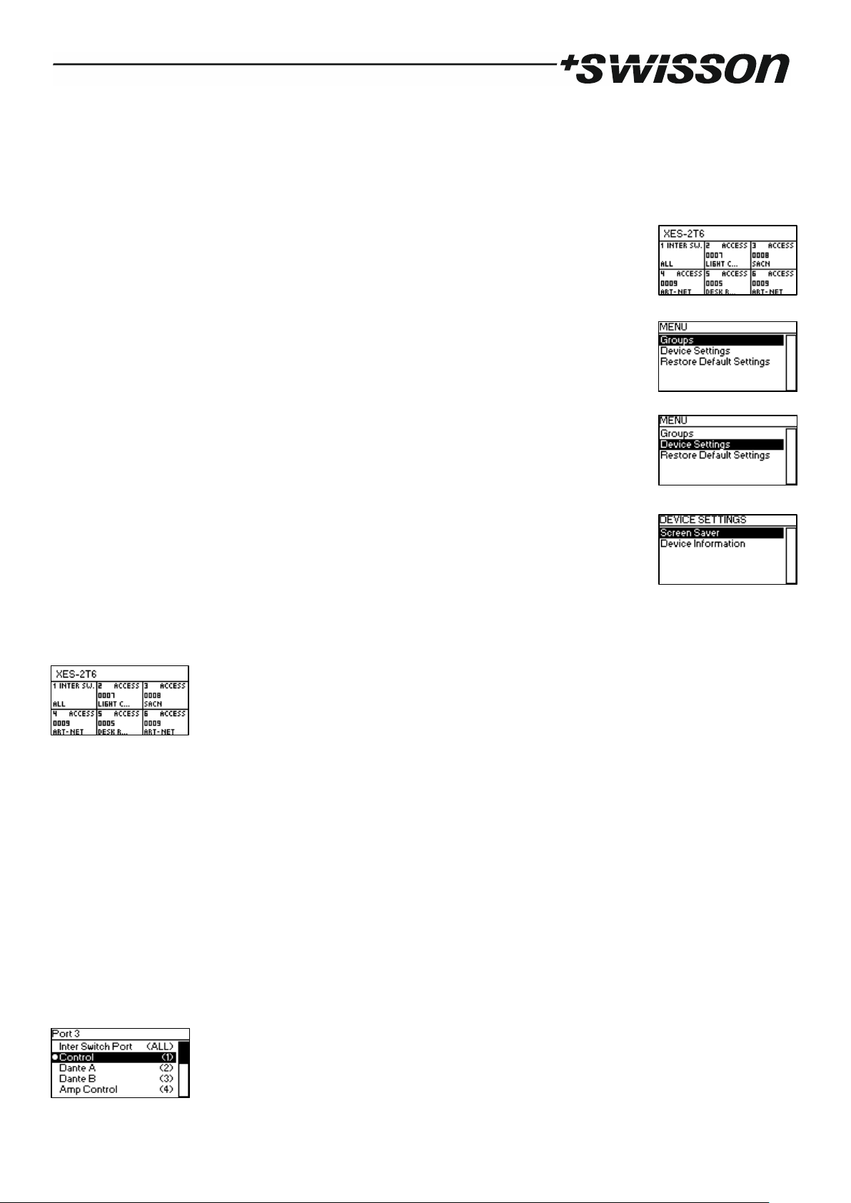
The following notation is used to describe locations in the menu: Home > Menu > Sub menu > …
For example, the manual could say “navigate to Home > Menu > Device Settings”. This can be read as follows:
Keep [Cancel] pressed for 2 seconds to reach the home screen.
Then, press [OK] to get to the menu.
Select “Device Settings” using the encoder wheel.
After pressing [OK] again to confirm the selection, the two items of the device settings menu
are shown.
Home Screen
The home screen displays the title XES-2T6, the area below is arranged into 6 cells. Each cell shows the number of its
associated numbered Ethernet port (see page 7, item 11). The small text next to the port number is either “INTER SW.”
or “ACCESS”. “INTER SW.” is displayed, if the corresponding port is configured to be connected to another IEEE 802.1Q
enabled switch and “ACCESS” is shown if the port is configured to connect an end device. More details on the differ-
ence between inter switch and access ports are given on page 9 under Groups (IEEE 802.1Q VLANs).
If the port is configured as an access port, the corresponding cell on the home screen shows the VLAN ID associated
with that port on the second line and on the bottom line, the beginning of the group label is displayed.
The cells associated with inter switch ports simply display “ALL” on the bottom left as a reminder that those ports pass
on and receive all groups (any VLAN ID).
Ethernet Port Configuration
To configure a numbered Ethernet port (see page 7, item 11), press the button next to it marked as item 13 on page
7. After that, the display will show the configuration screen for the selected port as shown below.

12
Use the encoder to highlight a group or choose the top most item if the port is to be used as an inter switch port. Once
the appropriate item is highlighted, push the encoder knob (press [OK]) to apply the setting.
Adding, Removing and Editing Groups
Adding a Group
The groups configuration menu is found under “Menu > Groups”. There, choose the bottom most item labelled “> Add
Group” using the encoder knob and push [OK] to add a new group.
The XES-2T6 supports up to 30 groups. When a total of 30 groups is present the “> Add Group” menu item disappears
until one of the groups has been removed.
Editing and Removing a Group
To edit a group, select a group using the encoder knob in the groups configuration menu under “Menu > Groups” and
press [OK]. On the OLED display, the group configuration menu depicted below will appear.
Editing VLAN ID
Highlight the top most item “VLAN ID” and push [OK] in order to edit the VLAN ID. You may then edit the last digit
using the encoder wheel. Please note that when the you continue to turn the encoder wheel counter clockwise when
the edited digit is 0, the edited digit rolls over to a 9 and one is subtracted from the digit to the left. Similarly, the digit
to the right is increased on a positive roll over.
When done, or if you need to edit another digit, press [OK] or [Cancel].
You may now use the encoder wheel to select another digit to edit. Push OK, to edit that digit as described above. And
when done, press [Cancel] again.
When the correct number is shown, press [Cancel] once more.

13
Then push [OK] to apply the edited number or press [Cancel] to discard the changes.
Changing the Group Colour
Choose “Colour” and press [OK] to change the group colour. A selection of colours will appear. The currently configured colour of the group is marked with a bullet point on the left. While this menu is shown on the OLED display, all
the group colour LEDs (item (12d) on page 7) light in the currently highlighted colour. Push [OK] to change the colour
setting of the group being edited to that colour.
Editing the Label
Select “Label” and press [OK] to edit the label text as described next.
Deleting Text
To delete a text line or a part of it, position the cursor immediately to the left of the first character you want to have
deleted.
Then keep [OK] pressed and turn the encoder clockwise until all of the text that you wish to delete appears highlighted.
As you release the [OK] button, the highlighted text is removed.
Inserting or Appending Text
To append or insert text, move the cursor to the position where you want to add your text.
Then push the [OK] button and select a character to add.
Confirm your selection by pressing [OK].

14
Repeat the above steps for the remaining characters. Then, press [Cancel] to finish inserting characters.
Press [Cancel] again to quit the editor.
Press [OK] to store the changes or press [Cancel] to discard all changes.
Removing a Group
Remove a group by choosing “> Delete” with the encoder wheel in the group configuration menu (see Adding, Remov-
ing and Editing Groups on page 12) and pressing the encoder knob.
Device Settings and Information
Screen Saver
Under Screen Saver, a selection list is presented to you with the following options:
• Enable: Screen saver is enabled.
• Disable: Screen saver is disabled.
A bullet point is shown next to the currently active setting. Use the encoder wheel to select the desired setting and
push [OK] to apply the setting.
Please refer to the section Screen Saver on page 15 for more details about the behaviour of the screen saver.
Device Information
The following information about the device is available under Home > Menu > Device Settings > Device Information.
Model
The device model is reported as “XES-2T6”.
Boot Software
The full version number of the boot software.
Firmware
The full version number of the firmware.
Hardware
The hardware revision.
Restore Default Settings
The default settings can be restored under Home > Menu > Restore Default Settings. In this menu, you will be asked
whether you want to continue restoring all settings. Push [OK] to confirm or [Cancel] to abort.
This function will restore all settings to the defaults:

15
• All numbered Ethernet ports are configured as access ports of the group labelled “Control” with the VLAN ID
1.
• Screen Saver: Enabled.
• The following groups are defined:
o “Control”, VLAN ID: 1, Colour: Royal blue
o “Dante A”, VLAN ID: 2, Colour: Purple
o “Dante B”, VLAN ID: 3, Colour: Pink
o “Amp Control”, VLAN ID: 4, Colour: Dark blue
o “Desk Remote”, VLAN ID: 5, Colour: Orange
o “Radio”, VLAN ID: 6, Colour: Red
o “Light Console”, VLAN ID: 7, Colour: Olive
o “sACN”, VLAN ID: 8, Colour: Orange red
o “Art-Net”, VLAN ID: 9, Colour: Yellow
o “Video”, VLAN ID: 10, Colour: Lawn green
Screen Saver
If the screen saver is enabled, the OLED display will automatically turn itself off when no user input is received for 40
seconds in order to improve the durability of the product. Once the display is turned off, it can be turned on again by
pushing any button or by turning the encoder wheel by one unit in any direction.
The screen saver can be enabled or disabled under Home > Menu > Device Settings > Screen Saver, as described in the
subsection Screen Saver under Device Settings and Information on page 14.
Firmware Updates
Firmware updates will be provided on the product page on the Swisson website. For updating the firmware, a PC with
Windows (Vista or later) and a USB A to B cable (USB printer cable) is required. Please refer to the separate documentation also provided on the product web page for details about the process of updating the product’s firmware.
16
Technical Data
Ambient temperature .................................................................. -30°C…55°C (-22°F…131°F)
AC power ...................................................................................... 100 - 240 V nominal, 50/60 Hz
Typical power consumption ......................................................... 10 W
Ethernet (all ports) ....................................................................... 1000BASE-T and 10BASE-T / 100BASE-TX, auto negoti-
ating, auto MDI-X
Ethernet ports .............................................................................. 6 + 2
Ethernet switch type .................................................................... Layer 2 Ethernet switch
Address look-up engine ............................................................... 4000 entries
Packet buffer ................................................................................ 192 Kbytes
Art-Net/sACN capacity ................................................................. > 1000 simultaneous universes2
Dante capacity ............................................................................. Up to 128 channels per direction at 48 kHz2
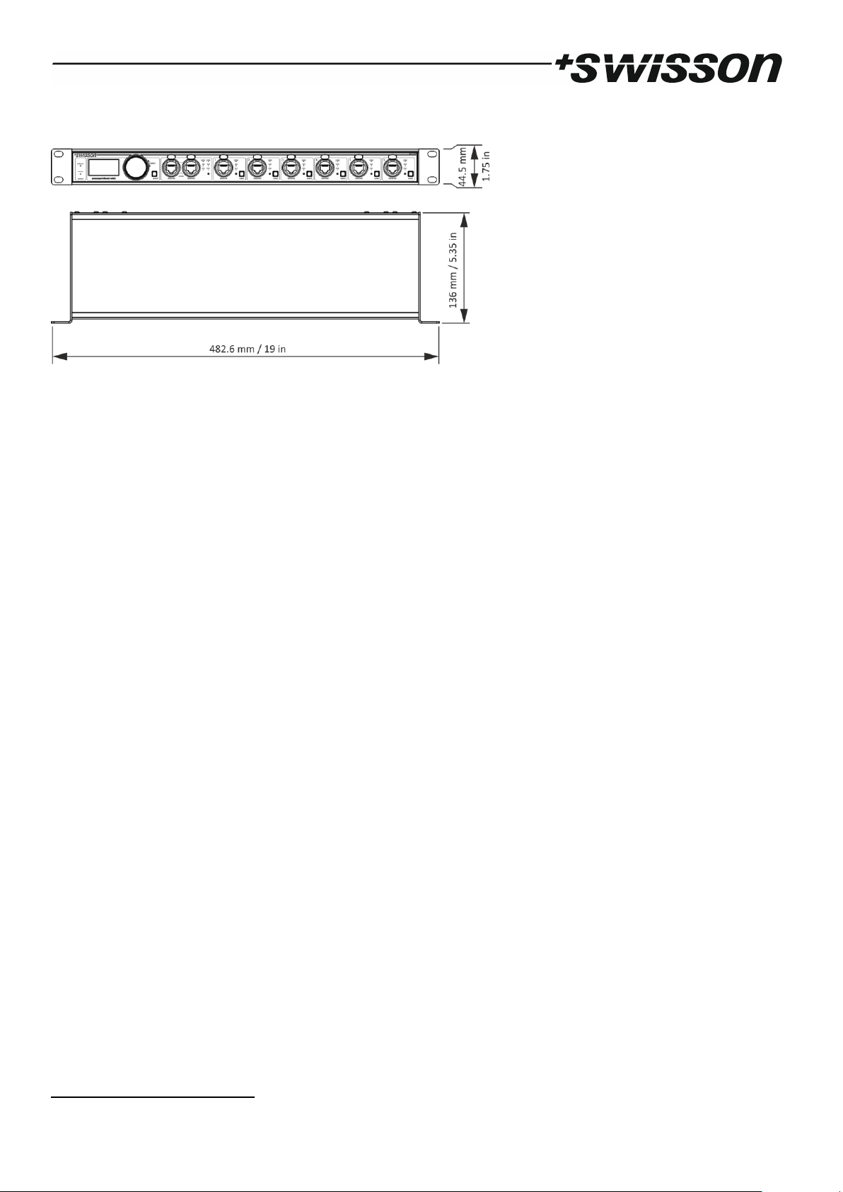
Dimensions
Depth ........................................................................................... 136 mm (5.35 in)
Width ........................................................................................... 482.6 mm (19 in)
Height ........................................................................................... 44.5 mm (1.75 in)
Weight .......................................................................................... 1.7 kg (3.75 lb.)
2
Estimate under the assumption that the full bandwidth is available to this application.

17
Ordering Information
10 42 20 XES-2T6 Premanaged Gigabit Ethernet switch, rack mountable

18

19

No part of this documentation may be reproduced or transmitted in any form or by any means, electronic or mechanical, including photocopying and recording, without the prior written permission of Swisson AG.
The information in this documentation is supplied without warranty of any kind, either directly or indirectly, and is
subject to change without prior written notice.
Swisson, its employees or appointed representatives will not be held responsible for any damages to software, hardware, or data, arising as a direct or indirect result of the product(s) mentioned herein.
28.11.2018
SWISSON AG SWISSON of AMERICA Corp.
Fabrikstrasse 21 2419 East Harbor Blvd.#3
CH-3250 Lyss Ventura, CA 93001
Switzerland U.S.A.
E-Mail: welcome@swisson.com
 Loading...