

Page 1
Visit us at : www.swisherinc.com
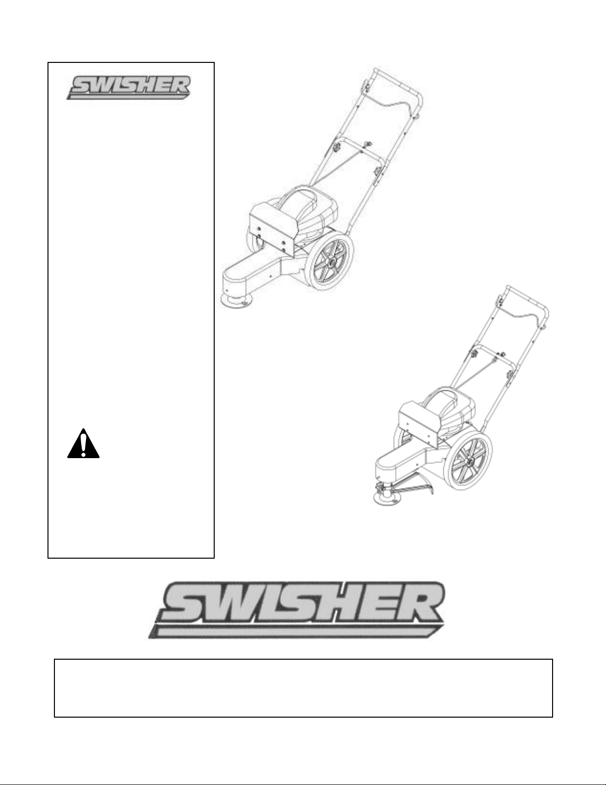
OWNER’S
MANUAL
MODEL NO.
ST50022STDQ
ST60022Q
ST60022DXQ12RK
ST65022Q
ST65022DXQ
ST6002212V
IMPORTANT
Read and follow all
Safety Precautions
and Instructions
before operating this
equipment.
Trim-N-Mow
Trim-Max
Assembly
Operation
Service and Adjustment
Rev 04-096
Repair Parts
1602 CORPORATE DRIVE, P.O. BOX 67, WARRENSBURG, MISSOURI 64093
PHONE 660-747-8183 FAX 660-747-8650
Manufacturing quality lawn care equipment since 1945
OTRIMSTD03
Made In The
USA
Page 2

LIMITED WARRANTY
The manufacturer’s warranty to the original consumer purchaser is: This product is free from defects in
materials and workmanship for a period of two (2) years from the date of purchase by the original consumer
purchaser. We will repair or replace, at our discretion, parts found to be defective due to materials or
workmanship. This warranty is subject to the following limitations and exclusions:
1) Engine Warranty All engines utilized on our products have a separate warranty extended
to them by the individual engine manufacturer. Any engine service
difficulty is the responsibility of the engine manufacturer and in no way
is Swisher Mower Co., Inc. or its agents responsible for the engine
warranty. The Briggs & Stratton Engine Service Hot-Line is 1-800-233-
3723. The Tecumseh Engine Service Hot-Line is 1-800-558-5402.
2) Commercial Use This product is not intended for commercial use and carries no
commercial warranty.
3) Limitation This warranty applies only to products which have been properly
assembled, adjusted, and operated in accordance with the instructions
contained within this manual. This warranty does not apply to any
product of Swisher Mower Co., Inc., that has been subject to alteration,
misuse, abuse, improper assembly or installation, shipping damage, or to
normal wear of the product.
4) Exclusions Excluded from this warranty are normal wear, normal adjustments, and
normal maintenance.
In the event you have a claim under this warranty, you must return the product to an authorized service
dealer. All transportation charges, damage, or loss incurred during transportation of parts submitted for
replacement or repair under this warranty shall be borne by the purchaser. Should you have any questions
concerning this warranty, please contact us toll-free at 1-800-222-8183. The model number, serial number,
date of purchase, and the name of the authorized Swisher dealer from whom you purchased the mower will
be needed before any warranty claim can be processed.
THIS WARRANTY DOES NOT APPLY TO ANY INCIDENTAL OR CONSEQUENTIAL DAMAGES
AND ANY IMPLIED WARRANTIES ARE LIMITED TO THE SAME TIME PERIODS STATED
HEREIN FOR ALL EXPRESSED WARRANTIES. Some states do not allow the limitation of
consequential damages or limitations on how long an implied warranty may last, so the above limitations or
exclusions may not apply to you. This warranty gives you specific legal rights and you may have other
rights, which vary from state-to-state. This is a limited warranty as defined by the Magnuson-Moss Act of
1975.
2
Page 3

Read, understand and follow all instructions in the manual and on the trimmer
Safety Instructions
This Safety Alert Symbol indicates important messages in this
manual. When you see this symbol, carefully read the message that
follows and be alert to the possibility of personal injury.
•
before starting
Read this manual carefully. Become familiar with the controls and how to
•
operate the unit properly.
Only allow responsible adults, who are familiar with the instructions, to
•
operate the unit.
Clear the area of objects such as rocks, toys, etc. that could be thrown by the
•
unit.
Be sure the area is clear of other people before trimming. Stop the unit if
•
anyone enters the area.
Be aware of the direction of the trimmer discharge and do not direct it at
•
anyone. Do not direct trimmer discharge at breakable objects, such as
windows, etc.
Do not operate trimmer without all guards and shields in place.
•
Never leave the machine running unattended.
•
Trim only in daylight or good artificial light.
•
Do not operate the trimmer while under the influence of alcohol or drugs.
•
Watch for traffic when operating near roadways.
•
Use the trimmer as the manufacturer intended and as described in the
•
manual.
Do not operate trimmer if it has been dropped or damaged in any manner.
•
Always have the damage repaired before operating.
Always wear safety glasses or eye shields when using the trimmer.
•
Dress properly. Do not operate the trimmer when barefoot or wearing open
•
sandals. Wear only solid shoes for good traction when trimming. Wear long
sleeved shirts or jackets, also long pants. Do not trim in shorts.
Keep your eyes and mind on your trimmer and the area being trimmed.
•
Do not let other interests distract you.
•
Do not put hands and feet near or under rotating parts.
•
Before cleaning, inspecting or repairing your trimmer, stop the engine and
•
disconnect the spark plug wire and keep it away from the spark plug to
prevent accidental starting.
Do not operate the trimmer if it vibrates abnormally. Excessive vibration is a
•
sign of damage. Stop the engine and safely check for damage and repair as
required.
Do not operate the trimmer in wet grass, where good footing may not be
•
possible. Walk; never run
Stop the trimmer when crossing gravel drives, etc.
•
3
Page 4

Slopes are a major factor related to loss of control and slip accidents,
Slope Operation
•
•
Us e extra care w he n ap pro ach in g blin d co rn ers, sh ru bs , tre es o r o the r o bjec ts
which can result in severe injury. All slopes require extra caution. If you
feel uneasy on it do not trim it.
DO: T rim across the face of a slope and not up and down .
• DO: R em ove objects such as rocks, tree lim bs, etc.
• DO: W atch for holes, ruts or bum ps. Tall grass can hide obstacles.
• DO NO T: Mow near drop-offs, ditches or embankm ents. T he opera tor could
loose footing or balance.
• DO NO T: Trim excessively steep slopes
• DO NO T: Trim on wet grass. R educed footing could cause slipp ing.
Children
Ke ep c hildre n ou t of th e a re a an d un der the w atch ful care o f anothe r
re sp on sib le a du lt.
• B e a lert a nd turn th e m achin e off if ch ildren en te r the a re a.
• B efo re a nd w he n ba cking , loo k be hind and d own for sm a ll c hild re n.
• N eve r a llow child ren to o pe ra te th is m ac hine .
•
th at m ay obstruc t vision .
Service
• Us e e xtra ca re handlin g gasoline and o the r fuels. T hey are flamm able a nd
vapo rs are exp lo sive.
• Us e o nly a n appro ved co nta ine r.
• Ne ve r rem o ve gas ca p or add fue l with th e eng ine running.
• Allo w en gin e to co ol be fo re refue ling. Do not sm oke
• Ne ve r refu el the m ach ine indo ors.
• Ne ve r store the m ach ine o r fu el co ntainer where the re is an op en flam e , such
as a w ater hea ter.
• Ne ve r run a m achin e inside a close d a rea.
• Ke ep nu ts an d b olts tigh t an d equ ipm e nt in g ood condition.
• Ne ve r tam p er w ith safe ty de vice s.
• Ke ep m ach ine free of gra ss, leaves or othe r de bris bu ild u p. C lea n o il o r fue l
spillage . A llo w m ach ine to coo l befo re storing.
• Stop a nd in spect th e equipm e nt if yo u strike an object. R epa ir if necessa ry
befo re restarting.
• Ne ve r m a ke re pairs o r ad justm en ts w ith the en gin e ru nning.
4
Page 5
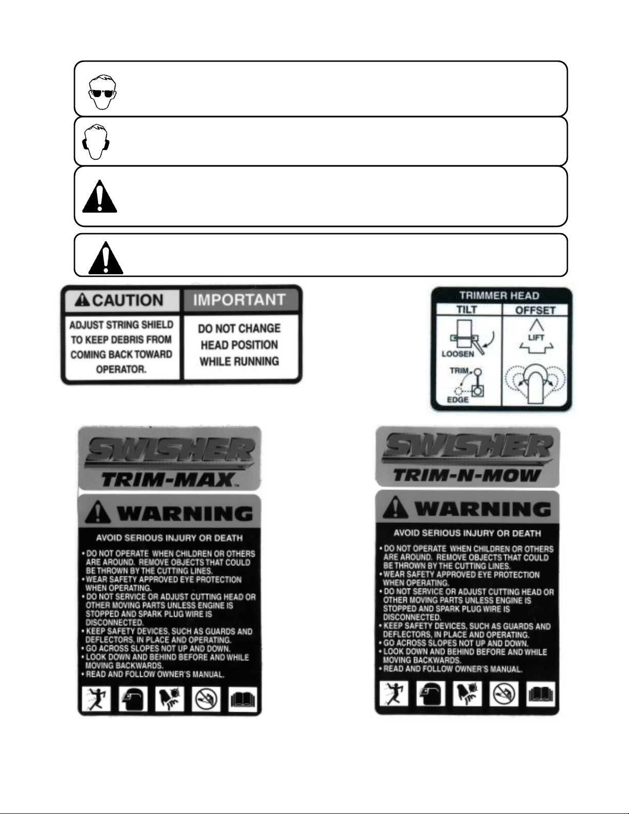
The operation of any cutter can encounter foreign objects to be thrown into the eyes, resulting in
severe eye damage. Always wear certified safety glasses or wide-vision safety goggles for over
spectacles before staring any cutting machine and while operating such a machine.
The operation of any cutter produces sound waves that are damaging to the human ear. Ear
protection is recommended.
CAUTION!
Tragic accidents can occur if the operator is not alert to the presence of children. Children
are often attracted to the machine and the mowing activity. Never assume that children
will remain where you last saw them.
Do not operate the trimmer if it vibrates abnormally. Excessive vibration is a sign of
Damage. Stop the engine and safely check for damage and repair as required
Trimmer Head
Instruction Decal
OD68
Caution Notice Decal
OD67
Trim-Max Decal
OD64
Trim-N-Mow Decal
OD65
5
Page 6

Assembly
Contents of Box:
Trimmer
•
Parts bag containing:
•
Manual
•
Engine manual
•
Safety goggles
•
Bottle of engine oil
•
4 sets of .155 trimmer line
•
Tools Required:
½” wrench
•
Handle Adjustment
Installation of handles
Remove loose fasteners from lower handles.
•
Pivot handles up and align lower hole in handles with hole on trimmer frame.
•
Install hardware removed in previous step. Snug, but do not tighten bolts.
Pivot upper handles to fit the lower handles. Tighten knobs.
•
Adjust handles for comfortable operation.
•
Tighten all bolts.
•
Hold the control bail against the handle and slowly pull the engine recoil
•
handle rope out. Thread the rope through the holder in the center of the
lower handle.
Handles may be adjusted up and down and in and out for comfortable operation.
Install Yellow Plastic Sleeve On Tilt Handle
Applying soap to handle may ease installation
Slip yellow sleeve over handle
6
Page 7

Preparing Unit For First Use
•
To start the trimmer:
•
Fill e n gin e c ra nk ca se w ith o il. A b ottle h as bee n p ro vid e d w ith th is un it. D O
N O T O V E R FIL L.
• Fill th e e n gin e fu el ta nk w ith g aso lin e. G A S O L IN E S H O U LD B E A D D E D
O U T S ID E IN A W EL L-V E N T ILA T E D A R E A .
• C he ck to e n su re s trin g h a s b ee n in sta lled p rop e rly. A d ia gra m is p rov id e d
ju st a bove th e w h eel for p ro pe r ins ta lla tio n.
Operation
Important! To ensure proper operation, clean the engine and trimmer
regularly. See page for details.
•
Remove any built up debris from engine.
• Pull control bail against the handle and hold.
• Push primer button on engine as directed.
•
Pull back sharply on recoil starter handle.
• Begin trimming.
Important! For safest operation, make sure debris is directed away from you and others.
Important! 12 Volt Units. For optimum battery performance, you should run engine for at least 15
minutes after each start to keep battery charged
To stop the trimmer:
• Release the control bail. Engine will stop immediately.
Trimming Hints
D o n ot lift th e trim m e r h ea d w h en trim m in g. L e t the he ad res t lig htly touching
th e g ro un d.
• K e ep a n e ye o n the len gth o f th e trim m er string s. A s the string s get s ho rter
th ey b e com e les s effe ctive at c utting an d w ill ta ke lo ng er to trim pro pe rly .
R ep la ce th e string as n ecessa ry. (S e e ins ta lling s tring)
• D o n o t trim w e t g ras s.
• U se ca ution w he n trim m in g s lo pe s.
• U se the pro pe r le ng th of s tring . U s in g a s tring to o long fo r th e u nit w ill ca us e
stallin g a nd u n acc ep ta ble o pe ration .
7
Page 8

Installing String
The head may also be tilted slightly to trim closer. This may
Important! Use the proper length of string. Using a string too long for the unit will
cause stalling and unacceptable operation.
3 – 5 HP use 16” String
5+ HP use 18” String
• Loosely fold string in half.
• Place loop of string against outside of loop on the trimmer head.
• Bring ends around and through the loop and over the string loop.
• Pull ends to tighten loop.
Trim-Max Operation
The Trim-Max trimmer is designed to also be used as an edge trimmer and to
offset left to right for easier close trimming.
Edge trimming/ Bevel Cutting
The trimmer disk may be tilted from horizontal to vertical so that it may be used
as an edge trimmer.
be handy for trimming foundations without damaging the siding.
To Tilt:
• Stop unit.
Make sure head is in the straight forward position. (see offset operation)
•
Loosen the trimmer tilt clamp lever. (Clockwise)
•
• Tilt head to desired position.
Tighten trimmer tilt clamp lever. (Counter Clockwise)
•
Adjust Lower trimmer shield to keep debris from coming back at operator.
•
Offset trimming.
The trimmer head may be offset to the left or right to allow trimming under
bushes, etc.
To Offset:
• Stop unit.
Raise offset lever.
•
Push or pull handles to achieve desired offset.
•
• Release offset lever. Make sure head has locked into position.
Adjust lower trimmer shield to keep debris from coming back at operator.
•
Important! Note direction of debris when offsetting head.
Offsetting trimmer to the left is recommended.
Trim-Max Tilt Adjustment
Direction Of Debris
OD63
Trim-Max Pivot Adjustment
8
Page 9

Engine
H an d le G as o line w ith c a re . D O N O T sm o k e o r us e o p en f la m e n e ar g as o lin e .
sp e ed the e n g in e ; s ev er e
Trimmer Maintenance
WARNING
–
ALWAYS STOP ENGINE AND DISCONNECT SPARK PLUG
M a ke s u re yo u r trim m er is in s a f e w o rk in g c o n d itio n b y ke e pin g th e fo llo win g
gu id e lin es in m ind e v e r y tim e y ou u se y o u r trim me r.
K ee p trim m er in g oo d o p era tin g c o n d itio n a nd k e ep a ll g u ard s a nd sh ie ld s in
•
pla ce . D O N O T o p e ra te th is tr im m er if a n y o f th e sh ield s a n d g u a rd s a re
m iss in g .
C he c k a ll f a s te n e rs fo r s e cu re fit to k ee p e q uip m e n t in s afe w o rk in g o rd er .
•
M a ke a d ju stm e n ts a s n e c e ss a ry.
T o re du ce f ire h a za rd s , k ee p e ng in e fr e e o f gra ss le a ve s o r e xc e ssiv e g r ea se .
•
D O N O T o p e ra te trim m e r w ith a d a m a ge d o r m is sin g m u ffle r. D O N O T
•
ta m p e r w ith ex h a u s t sy s te m ; th is m ay c a u se a fire h a za rd .
D O N O T o p e ra te e n g in e if a ir c le an e r o r the co ve r o v er th e c a r bu reto r a ir
•
in ta k e is m is sin g. R em ova l o f th e se p a r ts c ou ld c rea te a f ire h a za rd .
B efo re c le a nin g, m a kin g a dju stm e n ts o r re pa ir in g th e trim m er, S T O P e n gin e,
•
dis c o nn e c t sp a r k p lu g w ir e a n d a llo w e n gin e to c oo l.
•
U se o n ly a p pro ve d g a so line c on ta ine rs. N e ve r fu e l o r ru n trim m e r in p o orly
ve ntila te d a re as , s uc h a s a g a ra ge o r u tility b u ild in g .
A lw a ys re p la ce f ue l ta nk c a p. B e s ur e to c le an up an y s p ille d g a s o line .
•
D o n o t c ha ng e th e e n g ine g o v e rn o r s ettin gs o r ov er-
•
in ju ry o r d am ag e m ay re s u lt.
N ev er s to re m o w er, w it h g as olin e in th e ta nk , in sid e a b u ild in g w h ere fu m es
•
m a y re ac h a n o p en f la m e o r sp a rk . A lw ay s a llo w e n gin e to co o l b efo re
sto rin g
N EV E R A D D G AS O L IN E T O A H O T E N G IN E – A LL OW E N G IN E T O C O O L
B E F O R E A D D I N G G A S O LIN E
WIRE BEFORE PERFORMING ANY ADJUSTMENTS OR SERVICE
•
Refer to the engine s e rvic e m anual pro vid ed w ith th is u n it.
Belt
•
Oc c as ionally check th e belt for w ea r. A worn belt sho u ld be re placed
Belt A djus tm ent
.
• The TR IM -N -M OW h a s an a utom atic belt tig h tener a n d needs no furth e r adjustm ent
•
The TR IM -M AX ha s an a utom atic belt tig htener that a u tom atic a lly adju s ts when th e head is
tilted . If you d o not regularly tilt th e head on yo ur trim m er, it is reco m m e n d e d th a t yo u loos e n
the head tw ice a ye ar. (Se e edge trim m ing)
Belt R eplacem ent
• Rem ove fro nt be lt cover.
• Push trim m er h e a d toward b a c k of unit, com pre ss ing tensio n e r spring.
• Rem ove old b e lt.
• Install n e w belt by first routing b elt under the engin e and aro u nd the e n g ine p u lle y.
• Push trim m er h e a d toward b a c k of unit, com pre ss ing tensio n e r spring.
• Install b e lt over front pulley.
• Rele as e trim m er head. Ensure that be lt is cor rectly ins talled in the gr o o ve of th e eng ine a n d
front pulle ys.
Re install fro n t b elt shie ld.
9
Page 10

Trim-N-Mow
17
14” Wheel
Part # 2002
4
3
6
3 3
11
7
1
18
19
10
2
16
15
14
11
3
13
3
11
12
5
3
11
9
11
Paint Reference Chart
3
8
See Detail Page 11
Item # Description Part # Item # Description Part #
1 Briggs & Stratton Engine N/A 13 Lower Handle 2089
2 Trimmer Pulley & Washer 2065 14 Black Plastic Knob 2030
3 5/16-18 X 3/4 Serr Flg Bolt NB596 15 Upper Handle 2016
4 Metal Debris Shield 2092 16 Operator Presence Bail 2020
5 Rear Cover 2026 17 Rope Guide 2046
6 Belt Guard 2019 18 5/16-18 Jam Nut NB173
7 Blade Belt 2113 19 5/16-18 Nyloc Nut NB181
8 Rubber Shield 2027 Not Shown 5/16-18 X 2 Carriage Bolt NB590
9 Lower Motor Base 2006 Not Shown 3/8-24 X 1 Engine Bolt Locktite NB238N
10 5/16-18 X 1 1/4 Serrated Flange Bolt NB253 Not Shown SP Washer Bellvl. PLN .413 X .945 X .118 NB607
11 5/16-18 Serrated Flange Nut NB170 Not Shown 5/16-18 X 1 1/4 Serrated Flange Bolt NB253
12 Upper Motor Base 2005 Not Shown Operator Presence Cable 2034B
Color Paint Code
Texture Black TK
Texture Red TC
10
Page 11

Trimmer Head
Assembly for Standard
1
3
4
8
6
2
11
5
9
10
7
Paint Reference Chart
Item # Description Part #
1 5/8-11 2 Way Lock Jam Nut NB595
2 Blade Pulley- 4.5" 2049
3 5/8 ID X 1 OD 14 GA Washer NB149
4 Blade Bearing B985-8
5 Compression Spring 2033
6 Head Weldment SUBSTD-A
7 Std Trimmer Stabilizer Weldment 2032
8 Spinner Shaft 2024
9 Trimmer Spinner Disc Weldment 2021
10 Threaded Roller 2035
11 Trimmer Slide Weldment 2007
Color Paint Code
Texture Black TK
Texture Red TC
Trimmer Head
Assembly for Deluxe
and 12V Deluxe
Item # Description Part #
12 Blade Bearing B98
13 Head Weldment 2110
14 Bearing Sleeve 2023
15 Spinner Shaft 2124
16 Trimmer Slide Weldment 2107
17 Knob - Yellow 2079
18 Tilt Clamp U Bolt 2075
19 5/16-18 Nyloc Nut NB181
20 Handle Assembly 2080
19
19
20
1
2
3
5
1817
16
14
15
9
12
13
11
10
Page 12

Trim-Max Axle Setup
5
1
3
4
7
Deluxe Axle
6
2
7
3
4
4
12 Volt Deluxe Axle
Item # Description Part #
1 16" Wheel 2003
2 16" Steel Spoke Wheel 2094
3 #3 Hair Pin NB127
4 1/2 USS Flat Washer ZP NB555
5 Axle 2025
6 Axle (Zinc Plated) 2093Z
7 Axle Plate 2106
12
Page 13

17
Deluxe
Paint Reference Chart
Color Paint Code
Texture Black TK
Texture Red TC
4
24
5
16
14
1
22
2
15
18
25
3
25
24
21
23
20
12
19
13
9
6
11
10
25
24 8
See Detail Page 11
7
Item # Description Part # Item # Description Part #
1 Briggs & Stratton Engine N/A 16 Upper Handle 2016
2 Engine Pulley- 6" 2065 17 Operator Presence Bail 2020
3 Sheild Strap 2018 18 5/16-18 X 2 Carriage Bolt NB590
4 Acrylic Shield 2017 19 Spring 2069
5 Belt Guard 2119 20 Pivot Stop 2040
6 Blade Belt 2113 21 Rear Cover 2126
7 Lower Shield Sub Assy. 2076 22 Handle Grip, Pivot 2077
8 Rubber Shield 2127 23 Spacer B99S
9 Wear Strip 2116 24 5/16-18 X 3/4 Serr Flg Bolt NB596
10 Pivot Plate Weldment 2073 25 5/16-18 Serrated Flange Nut NB170
11 Lower Motor Base 2006 Not Shown 3/8-24 X 1 Engine Bolt Locktite NB238N
12 5/16-18 X 1 1/4 Serrated Flange Bolt NB253 Not Shown SP Washer Bellvl. PLN .413 X .945 X .118 NB607
13 Upper Motor Base 2005 Not Shown 5/16-18 X 1 1/4 Serrated Flange Bolt NB253
14 Lower Handle 2015 Not Shown Operator Presence Cable 2034B
15 Black Plastic Knob 2030
13
Page 14

12 Volt Deluxe
Paint Reference Chart
Color Paint Code
Texture Black TK
Texture Red TC
1
2
3
For Additional Parts
See Page 13
Item # Description Part #
1 12 Volt Handle Sub-Assy- Lower 2089-12V
2 Battery for Weedtrimmer 2101
3 Battery Cover 2105
Not Shown Wiring Harness 2120B
Not Shown Key Switch 2102
Not Shown Keys For Key Switch (set of two) KSK
14
Page 15

Notes
15
Page 16

OWNER’S
MANUAL
MODEL NO.
Visit us at: www.swisherinc.com
Each trimmer has its own model number. Each engine has its
own model number. The model number for the trimmer will be
found on the right hand side of the drive belt housing. The
model number for the engine will be found on the top of the
blower fan housing.
All trimmer parts listed herein may be ordered directly from
Swisher Mower & Machine Co. Inc. or your nearest Swisher
dealer.
All engine parts may be ordered from the nearest dealer of the
engine supplied with your mower
.
ST40022STDQ
ST60022Q
ST65022Q
ST65022DXQ
ST6002212V
WHEN ORDERING PARTS, PLEASE HAVE THE
FOLLOWING INFORMATION AVAILABLE:
* PRODUCT – TRIMMER
* SERIAL NUMBER - _______________
* MODEL NUMBER - _______________
* ENGINE MODEL NUMBER - _______________
TYPE - _______________
* PART NUMBER WITH PAINT CODE
* PART DESCRIPTION
TELEPHONE - 1-800-222-8183
FAX - 1-660-747-8650
SWISHER MOWER & MACHINE CO. INC.
1602 CORPORATE DRIVE
P.O. BOX 67
WARRENSBURG, MO 64093
SWISHER MOWER & MACHINE CO. INC.
PRINTED IN U.S.A.
 Loading...