

Page 1

REPAIR MANUAL
ROUGH CUT
44” TRAIL CUTTER
Swisher Mower Co
Warrensburg, MO
Page 2

LIMITED WARRANTY
The manufacturer’s warranty to the original consumer purchaser is: This product
is free from d e fects in materials and workman s h ip fo r a p eriod of one (1) year
from the date of purchase by the original consumer purchaser. We will repair or
replace, at our discretion, parts found to be defective due to materials or
workmanship. This warranty is subject to the following limitations and
exclusions:
1) Engine Warranty All engines utilized on our products have a separate
warranty extended to them by the individual engine
manufacturer. A n y engine service difficu lty is the
responsibility of the engine manufacturer and in no
way is Swisher Mower Co ., Inc. or its agen ts
responsible for the engine warranty. The Briggs &
Stratton Engine Service Hot-Line is 1-800-233-
3723. The Tecumseh Engine Service Hot-Line is 1800-558-5402.
2) Commercial Use The warranty period for this product used for
commercial or rental is limited to ninety (90) days
from the date of original purchase.
3) Limitations This warranty applies only to products which have
been properly assem b led , adju sted , and op erated in
accordance with the instructions contained within
this manual. This warranty does not apply to any
product of Swisher Mower Co., Inc., that has been
subject to alteration, misuse, abuse, improper
assembly or installation, shipping damage, or to
normal wear of the product.
4) Exclusions Excluded from this warranty are normal wear,
normal adjustments, and normal maintenance.
In the event you have a claim under this warranty, you must return the product to
an authorize d service dealer. All transp ortation charges, dama ge, or loss incurred
during transportation of parts submitted for replacement or repair under this
warranty shall be borne by the purchaser. Should you have any questions
concerning this warranty, please contact us toll-free at 1-800-222-8183. The
model number, serial number, date of purchase, and the name of the authorized
Swisher dealer from whom you purchased the mower will be needed before any
warranty claim can be processed.
Page 3

TABLE OF CONTENTS
1. If engine won’t crank
2. Engine cranks but won’t start
3. Wiring diagrams
4. Identification of wiring
5. Deck belt adjustment procedure
6. Repairing the blade driver assembly
7. Replacement parts – quick reference
Page 4
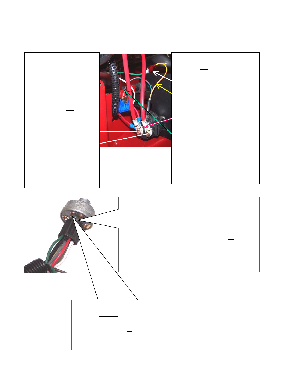
IF ENGINE WON’T CRANK
ALWAYS CHECK FUSE FIRST
TEST #1
Using a remote starter
switch or a suitable
device, make a connection
between the large
terminals on the solenoid.
If engine does not
crank!!!
•Battery may be weak or
dead
•Starter may be bad
•Battery cables may have
bad connections
•Do not go to Test #2
until this test gives results.
TEST #2
If engine did crank in test #1,
disconnect green wire at spade
connector and apply positive
voltage from the battery to the
yellow wire with the orange
stripe. The positive voltage can
also be picked up on the
solenoid terminal where the
fuse connects. Make sure the
green and black wire with the
eyelet is well grounded. If
engine doesn’t crank now,
replace the solenoid.
Remember, all other tests are
useless unless these two tests
make the engine turn over.
TEST #3
If engine did crank in the first part of test #2,
reconnect green wire to solenoid. Using a jumper
wire attached to the positive terminal of the battery,
apply 12 volts to the red wire on terminal B
ignition switch. Try to crank, using the ignition
switch. If engine cranks, the fuse or the fuse holder,
or related wiring is defective somewhere back to the
solenoid.
TEST #4
If engine did not crank in test #3, this time move the
jumper wire attached to the positive terminal of the battery,
to the green wire on S
Ignition switch does have to be activated for this test. If
engine cranks now, ignition switch needs replacing.
terminal of the ignition switch.
of the
Page 5
ENGINE CRANKS BUT WON’T START
Checks for electrical problems
•While turning ignition switch to its first position, listen for the fuel solenoid on the
carburetor to click. It must click to supply fuel to the carburetor.
•Try a new spark plug.
•Check for spark at plug when it is removed and the threaded end is grounded.
•Unplug the six-position socket that connects engine wiring to mower wiring harness.
Engine will still crank. If plug doesn’t have a spark now, ignition module is probably
defective.
Checks for mechanical problems
•Make sure the tank gas valve is turned on.
•Remove air filter element to check for signs of gas in the throat of the carburetor.
•If no gas, check to see if choke is working properly.
•If all above checks show positive, carburetor must have an internal problem. Remove and
clean the carburet or.
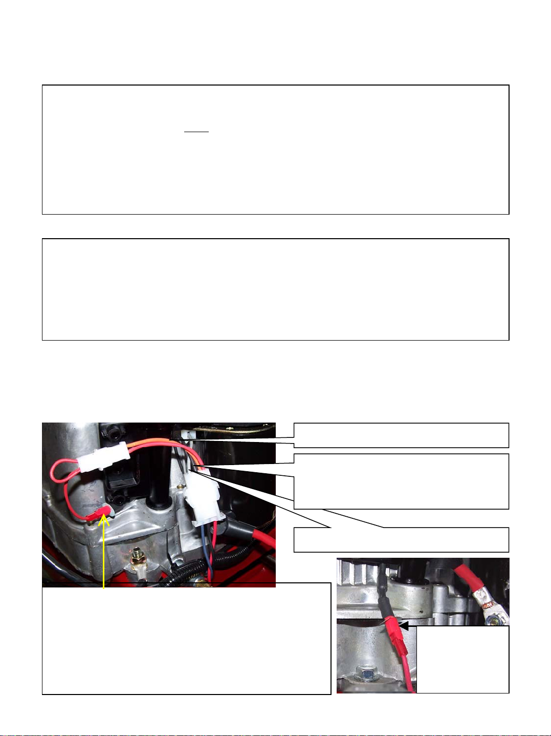
ENGINE WIRING SYSTEM
Used on the RTB14544
Orange is not used in this applicatio n
Black wire comes from the ignition
switch and goes to the ignition module
to shut engine off.
Gray wire goes to the fuel solenoid.
Red wire comes from engine’s alternator through a
diode to convert the voltage from AC to DC. A simple
test to check its outpu t is to measur e the voltage of the
battery before the engine is started. Now start the
engine, the voltage should rise about 1 volt when the
engine starts. This voltage will slowly drop back to
normal voltage as the battery becomes fully charged.
Alternator
charge wire
on the
RTB134412V
Page 6

WIRING DIAGRAMS
RECOIL START
10299
WHRT44-1
Page 7
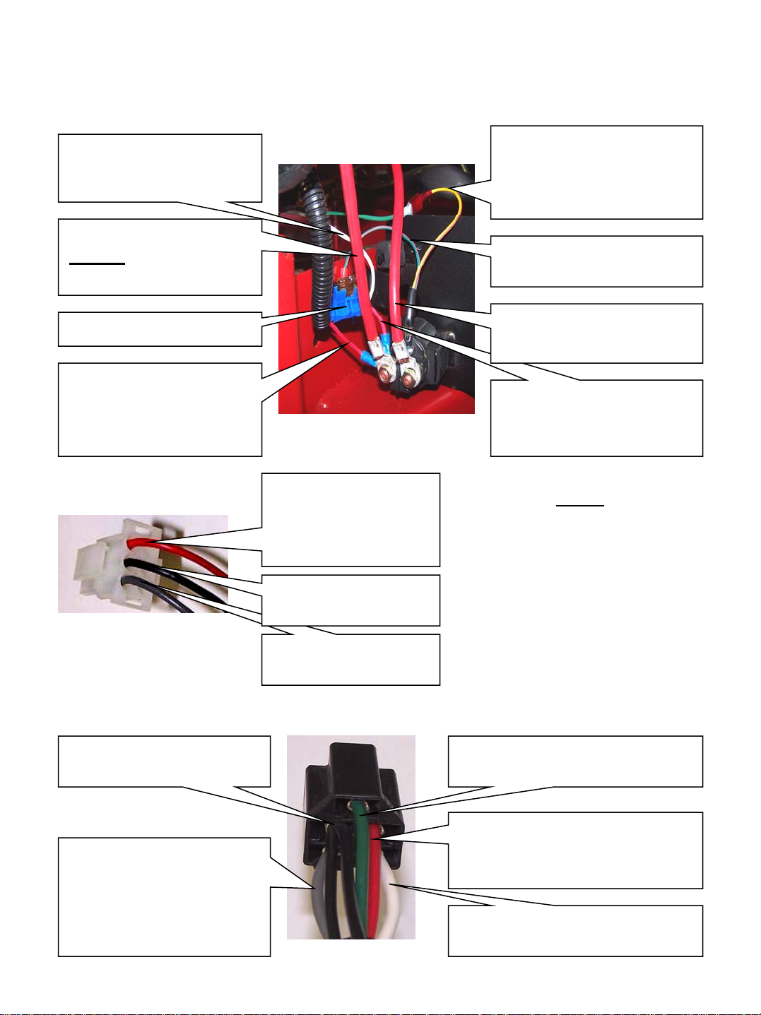
IDENTIFICATION OF WIRING
WIRING HARNESS AT STARTER SOLENOID
Grounded white wire goes
back to the ignition
switch.
Large red wire goes to the
positiveterminal of the
battery.
In line 5 amp fuse.
Red wire goes to the
engine plug and through
to the alternator on the
engine.
WIRING HARNESS
PLUG TO ENGINE
Red wire goes to the
same term ina l on
solenoid as the
positive battery cable.
Black wire goes to the
ignition switch
Gray wire goes to the
ignition switch.
Yellow and orange wire
from solenoid connects to
the green wire that goes to
the ignition switch.
Green and orange wire
goes to chassis ground.
Large red wire goes to the
engine starter.
Red wire goes through the
fuse and on to the ignition
switch.
NOTE
Engine plug is used only on the
14.5 HP Briggs engines. The
gray wire is not used on the
engines that have no fuel
solenoid on the carburetor.
WIRING HARNESS PLUG AT IGNITION
Black wire goes to the
engine plug
Gray wire goes to the fuel
solenoid on the carburetor.
Gray wire not used on the
engines that have no fuel
solenoid on the carburetor.
Green wire goes to the starter
solenoid.
Red wire goes to the fuse and
then on to the battery positive at
the solenoid terminal.
White wire goes to chassis
ground.
Page 8
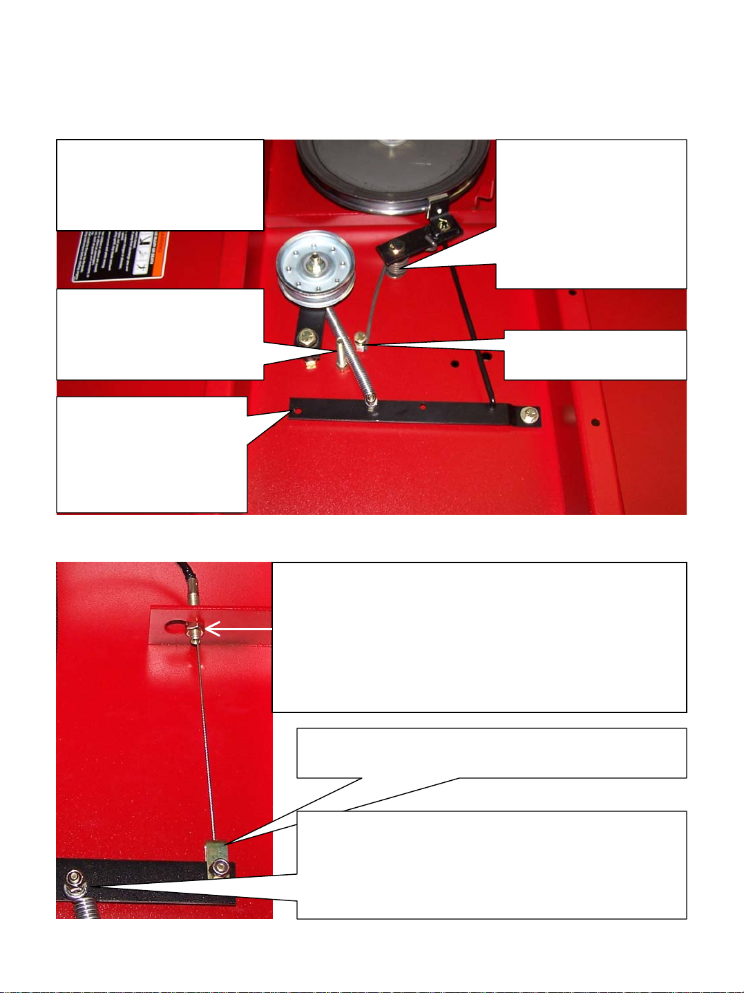
DECK BELT ADJUSTMENT PROCEDURE
ALL VIEWS WITH ENGINE AND GUARDS REMOVED
For easier access to the belt
engagement system when
doing major repair, remove
the engine with it’s mount.
This bolt stops the travel of
the idler before it strikes
the engine pulley if the belt
gets worn too thin.
As the belt idler tightens
the the belt to start the
blades turning it also
removes the brake from
the blade spindle pulley.
Blade brake is activated
by the torsion spring
around the pivot bolt. It
is important that brake
stop the pulley on the
blade assembly when the
clutch is disengaged.
Stop for the tail of the
torsion spring.
To increase the the tension on the drive belt, adjust this nut
and the one on the other side of the bracket, counter
clockwise. Always check the operation of the blade brake
on the spindle pulley after the adjustment, since they are
both affected by the adjustment of the cable. The stopping
point has to be when the brake is no longer able to contact
the blade spindle when the engagement lever is released.
This is the point where engagement cable is connected
when a replacement needs to be installed.
Never tighten the nut against the loop on the end of the
spring at this bolt or at the other end as it connects to
the belt idler. The spring must always have room to
rotate on the bolt or it will break off at that point.
Page 9

REPAIRING THE BLADE DRIVER ASSEMBLY
Pulley does not have a hub.
When removing, lift it off
like a washer, no gear
puller is needed.
Bearings are sealed. They can
be driven out and new ones
pressed in for repairing the
spindle assembly. It can also
be purchased as a unit for
easier repair.
Torque this nut to 120 ft/lbs
to keep blades from
tightening on the bolt during
use.
Torque top nut to 235
ft/lbs.Replacing this nut
each time it removed is
recommended.
Since there are no hubs on our
pulleys, this Belleville washer
is important to apply friction
between the nut and the
pulley to turn the shaft. Make
sure the outer lip is down to
best contact the pulley.
Spacer used to align the blade
pulley to the engine pulley.
Spacers are used between the
bearings to bear the torque
applied on the spindle bolt.
Washer is used to separate the
outer race of the bearing from
the stomp jumper.
Do not tighten against this
washer. The blades need to be
able to swing freely.
Insert the blade bolt through the blade and washer, then thread into the nut
welded on top of the stump jumper. Bring the bolt up snug to the blade then back it out
about half a turn. Tighten the locking nut on this bolt as it comes up above the welded nut
on the stump jumper. Torque this nut to 120 ft/lbs. If the nut is not secure enough, the bolt
will have a tendency to tighten on the blade and will eventually lock solid. It is imperative
that this blade swing freely on this bolt. When the blade locks up, the blade system gets out
of balance and the mower will shake violently and eventually break the deck around where
the spindle is mounted.
When doing major repairs on the under side of the deck, it might be easier
to tilt the deck on its front end. The only safe way to tilt an engine is with the spark plug
upward. That position allows the oil to go to the back of the crankcase and not forward past
the rings and into the combustion chamber. Also try to do the work while the gas is low in
the tank. Remove the hitch from the deck to make it easier to tilt the mower forward.
Page 10

REPLACEMENT PARTS
Quick Reference
Swisher Part # Description
•BA50 Belt
•10358 Blade (two required)
•4845 Blade driver bearing (two required)
•4872 Blade driver assembly
•B527 Belt idler
•9043 Starter solenoid
•3623 Ignition switch (for 12V start)
•KSM Ignition switch (for recoil start)
•BR20CC Blade engagement cable
•10385 Wiring harness (or recoil start)
•WHRT44-1 Wiring harness (for 12V start)
Console section; includes cable
BELT ROUTING DIAGRAM
P/N 4846
P/N B527
P/N BA50
P/N BB105
Page 11

This manual was produced at the beginning of
our 2006 production. It was specifically
written for those models built after January,
2006. For those models built before that time
refer to the owners manuals for specific parts or
call the Swi sher Mow er fa ct or y for ass i s tan c e.
For warranty issues or ordering parts for
the engines or the hydro units, contact the
authorized dealer in your area.
For additional assistance on service
Contact Swisher Mower Co., Inc.
Phone 1-800-222-8183
Fax 1-660-747-8650
E-mail cust.serv@swisherinc.com
Page 12

swisherinc.com
REPAIR
MANUAL
MODEL NO.
44”ROUGH CUT
TRAILCUTTER
Each mower has its own model number. Each engine has its
own model number. The model number for the mower will be
found on the right hand side of the motor mount. The model
number for the engine will be found on the top of the valve
cover.
All mower parts listed herein may be ordered directly from
Swisher Mower & Machine Co. Inc. or your nearest Swisher
dealer.
All engine parts may be ordered from the nearest dealer of the
engine supplied with your mower
.
RTB115441
RTB12544
RTB134412V
RTB14544
POLB10544HD
WHEN ORDERING PARTS, PLEASE HAVE THE
FOLLOWING INFORMATION AVAILABLE:
* PRODUCT – 44’’ TRAILCUTTER
* SERIAL NUMBER - _______________
* MODEL NUMBER - _______________
* ENGINE MODEL NUMBER - _______________
TYPE - _______________
* PART NUMBER
* PART DESCRIPTION
TELEPHONE - 1-800-222-8183
FAX - 1-660-747-8650
SWISHER MOWER & MACHINE CO., INC.
1602 CORPORATE DRIVE; P.O. BOX 67
WARRENSBURG, MO 64093
www.swisherinc.com
SWISHER MOWER & MACHINE CO.,INC.
PRINTED IN U.S.A.
 Loading...