

Page 1
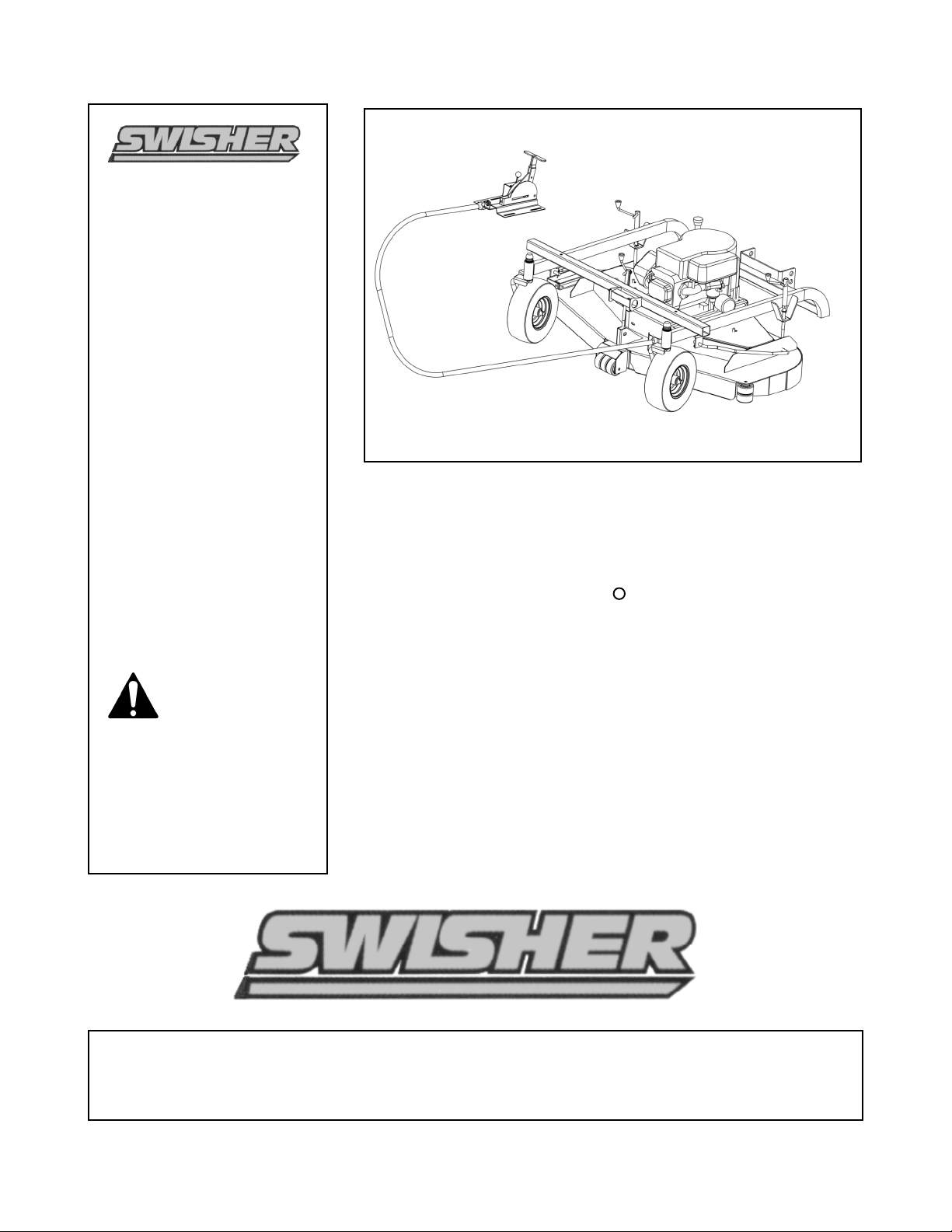
50” UNIVERSAL MOUNT
TRAILMOWER
For Vehicle Mounting Op tions See
Details On Page-16
OWNER’S
MANUAL
16 02 CORPORATE DRIVE, P.O. BOX 67, WARR ENSB U RG , MISSOURI 64 093
PHONE 660-74 7-818 3 FAX 660-7 47-86 50
MODEL NO.
Manufacturing quality lawn care equipment since 1945
Assembly
Operation
Service and Adjustment
Repair Parts
Mad e In T he
USA
Rev. 04-147
Read and f ollow all
Saf ety Precautions
and Instructions
before op erating this
equipment.
IMPORTANT
ONFT11 50
FT1150
R
Page 2

SAFETY PRECAUTIONS
•
Read the manual. Learn to operate this machine safely.
•
Always disconnect the spark plug wire and place the wire where it cannot contact
the spark plug, to prevent accidental starting the engine when setting up,
transporting, adjusting or making repairs.
•
Keep all shields and guards in place.
•
Understand the speed, steering and stability of this machine. Know the positions
and operations of all controls before you operate this machine. Check all of the
controls in a safe area before starting to work with this machine.
•
Allow only responsible adults who are familiar with these instructions to operate
this machine. Never allow children to operate this machine.
•
Clear the area of objects such as rocks, toys, wire, etc. that can be picked up and
thrown by the blade.
•
Be sure the area is clear of other people before mowing. Be aware of the mower
discharge direction and do not point at anyone. Stop the machine if anyone enters
the mowing area. Children are often attracted to the machine and the mowing
activity. Never assume that children will remain where you last saw them.
Keep children under the watchful care of another responsible adult.
•
No riders on this unit at any time.!
•
Do not put hands or feet near or under rotating parts. Keep clear of the discharge
opening at all times.
•
Do not mow in reverse. Always look down and behind before and while backing.
This Safety Alert Symbol indicates important messages in this
manual. When you see this symbol, carefully read the message that
follows and be alert to the possibility of personal injury.
Read this manual completely. This machine can amputate hands, feet, and throw
objects. Failure to observe the following safety instructions could result in serious
injury or death.
2
Page 3
•
Turn off the blades when not mowing. Before leaving the machine, turn off the
blades and stop the engine.
•
Watch for traffic when operating near or crossing roadways.
•
Do not operate the mower if it has been dropped or damaged in any manner or if
the mower vibrates excessively. Excessive vibration is an indication of damage.
Repair mower as necessary.
•
Dress properly. Do not operate the mower when barefoot or wearing open
sandals. Wear only solid shoes with good traction when mowing.
•
Do not operate the machine while under the influence of alcohol or drugs.
•
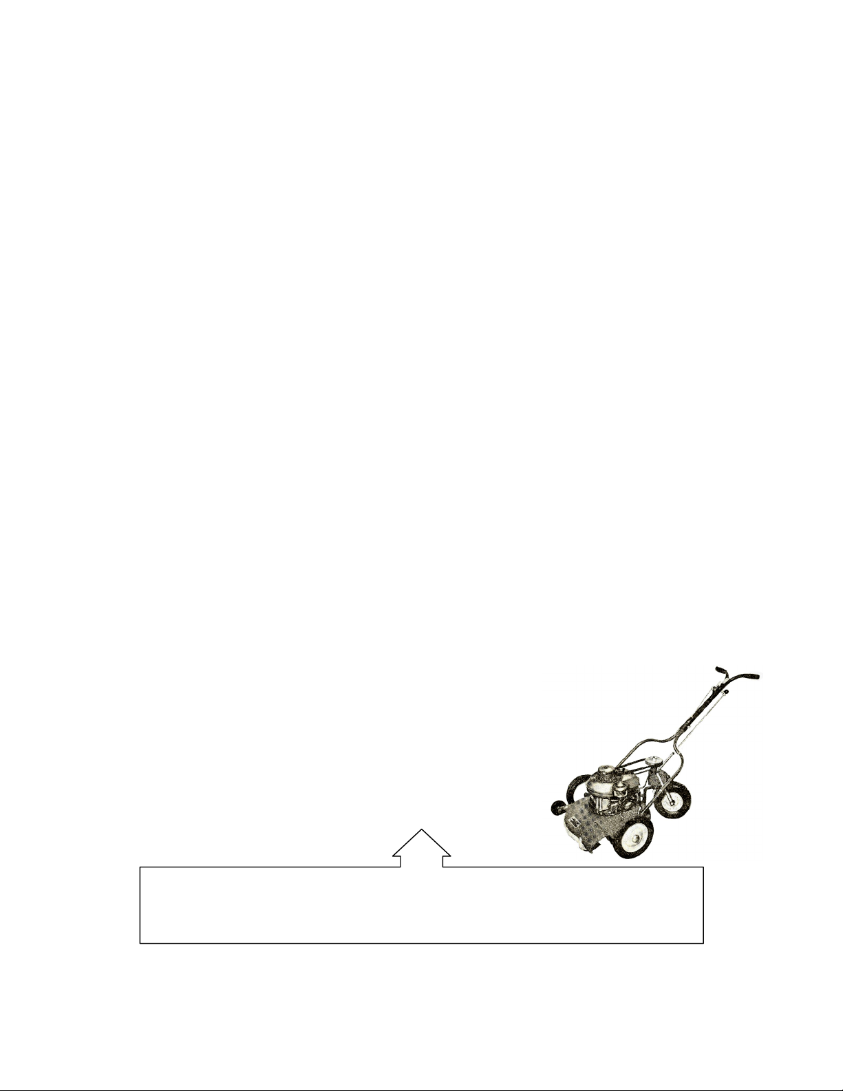
Operate self-propelled machines up and down slopes. There is significant risk of
overturns when operating across slopes. Operate walk-behind machines across
slopes. There is a significant risk of slipping under a walk-behind machine when
operating up and down slopes.
•
Never tamper with safety devices. Check their proper operation regularly.
•
Stop and inspect the equipment if you strike an object. Repair, if necessary,
before restarting.
•
Never make adjustments or repairs with the engine running.
•
Mower blades are sharp and can cut. Wrap the blades or wear gloves, and use
extra caution when servicing them.
3
? Did You Know ?
Swisher Mower & Machine Co. was started in 1945.
Page 4
4
Page 5

LIMITED WARRANTY
The manufacturer’s warranty to the original consumer purchaser is: This product is free from
defects in materials and workmanship for a period of one (1) year from the date of purchase by
the original consumer purchaser. We will repair or replace, at our discretion, parts found to be
defective due to materials or workmanship. This warranty is subject to the following limitations
and exclusions:
1) Engine Warranty All engines utilized on our products have a separate warranty
extended to them by the individual engine manufacturer. Any
engine service difficulty is the responsibility of the engine
manufacturer and in no way is Swisher Mower Co., Inc. or its
agents responsible for the engine warranty. The Briggs & Stratton
Engine Service Hot-Line is 1-800-233-3723. The Tecumseh
Engine Service Hot-Line is 1-800-558-5402.
2) Commercial Use The warranty period for any product used for commercial or rental
is limited to ninety (90) days from the date of original purchase.
3) Limitations This warranty applies only to products which have been properly
assembled, adjusted, and operated in accordance with the
instructions contained within this manual. This warranty does not
apply to any product of Swisher Mower Co., Inc., that has been
subject to alteration, misuse, abuse, improper assembly or
installation, shipping damage, or to normal wear of the product.
4) Exclusions Excluded from this warranty are normal wear, normal adjustments,
and normal maintenance.
In the event you have a claim under this warranty, you must return the product to an authorized
service dealer. All transportation charges, damage, or loss incurred during transportation of parts
submitted for replacement or repair under this warranty shall be borne by the purchaser. Should
you have any questions concerning this warranty, please contact us toll-free at 1-800-222-8183.
The model number, serial number, date of purchase, and the name of the authorized Swisher
dealer from whom you purchased the mower will be needed before any warranty claim can be
processed.
THIS WARRANTY DOES NOT APPLY TO ANY INCIDENTAL OR CONSEQUENTIAL
DAMAGES AND ANY IMPLIED WARRANTIES ARE LIMITED TO THE SAME TIME
PERIODS STATED HEREIN FOR ALL EXPRESSED WARRANTIES. Some states do not
allow the limitation of consequential damages or limitations on how long an implied warranty
may last, so the above limitations or exclusions may not apply to you. This warranty gives you
specific legal rights and you may have other rights, which vary from state-to-state. This is a
limited warranty as defined by the Magnuson-Moss Act of 1975.
5
Page 6
6
Page 7

STARTING THE ENGINE
•
See engine manufacturer’s instructions for the type and amount of oil and fuel used.
Engine must be level to accurately check and fill oil.
Do not overfill.
•
Park vehicle and mower on a level surface, set the vehicle parking brake, and disengage
blades.
•
Check spark plug wire, oil, and fuel.
•
Check all electrical connections.
•
Make certain console assembly is secured to vehicle.
•
Set engine throttle control to the “CHOKE” position.
•
Turn key switch to the “START” position
•
Set engine throttle at desired RPM.
STOPPING THE ENGINE
•
Turn key switch to the “OFF” position.
BREAKING IN YOUR MOWER
•
Set vehicle parking brake or chock wheels to prevent accidental rolling.
•
Start engine.
•
Engage blades.
•
In a safely monitored environment, i.e. no children, allow blades to rotate and engine to
idle for 5 minutes. This breaks in the belts and the engine.
•
Stop mower.
MOWER HEIGHT ADJUSTMENT
•
Never make any adjustments while mower is running.
•
The cutting range is approximately 1.5” to 4.5”. The height has been measured from the
ground to the blade tip without the engine running.
•
Rotate height adjust crank handles in a clockwise direction to lift the mower deck. A
counter-clockwise direction is used to lower the mower deck.
•
Make sure the height adjustment is the same at side crank handles. For best results, see
“SUGGESTED MOWING PRACTICE” section.
Graduated scales are for reference
only, not the actual cutter height
.
•
Place crank handle in a retracted position to maintain height adjustment.
START MOWING
•
Clear mowing area of debris.
•
Check vehicle to mower connection.
•
Start mower engine.
•
Engage clutch lever.
•
Begin mowing slowly.
CAUTION!
SHUT OFF MOWER ENGINE AND REMOVE SPARK PLUG WIRE FROM
SPARK PLUG BEFORE MAKING ANY ADJUSTMENTS TO THE MOWER.
7
Page 8

STOP MOWING
•
Bring vehicle to a full stop.
•
Disengage clutch lever by moving lever to center position.
•
Turn key switch to “OFF” position.
TRANSPORTING MOWER
•
Never transport unit with engine running.
•
If transporting unattached from tow vehicle, remove spark plug wire and place it where
contact with the spark plug cannot be made.
SUGGESTED MOWING PRACTICES
•
Operate mower engine at full throttle to assure the best cutting performance and
maximum material discharge.
•
Allow wet grass to dry. Clumps of wet grass will collect under the mowing deck.
•
Mowing should be started with tow vehicle in low gear and increased only as safe
mowing conditions permit. This speed should not exceed 5 MPH.
•
The average lawn should be cut to approximately 2.5” during the cool season and to over
3” during the hot months.
•
For a healthier lawn and better aesthetics, your lawn should be mowed often and after
moderate growth.
•
When cutting high or dense grass areas go slowly. Some areas may need to be cut twice.
The second cut should be at 90 degrees to the first, if possible.
•
Never remove more than 1/3 of the grass length at any one time
GENERAL TROUBLE SHOOTING
•
The mower does not cut level.
o
Level deck, making sure height adjustments are equal.
o
Check air pressure of all tires; make sure they are equal (about 25-30 psi).
o
Check blade attachment.
•
The engine will not start.
o
Disengage blades, turn toggle switch to “OFF” position, check all electrical
connections, and inspect spark plug and wire.
•
Engine runs poorly.
o
See engine manual.
o
Check throttle adjuster.
o
Replace fuel, clean fuel filter and fuel line.
IF PROBLEMS PERSIST HAVE A QUALIFIED MECHANIC SERVICE THE
MOWER. NEVER ATTEMPT TO MAKE AN ADJUSTMENT THAT YOU ARE
NOT SURE IS CORRECT. DOING SO CAN CAUSE OTHER PROBLEMS.
8
Page 9

SAFETY AND OPERATIONAL DECALS
Replace decal immediately if damaged. Order by part number from Swisher Mower and Machine Co. Inc.
OD33 – Speed Decal
OD45 – Warning Decal
OD55 – Triangle Danger Decal
9
Decal located
On grass chute
[not shown]
OD99- ON / OFF
DECAL
OD10--BLADE ENGAGE
DECAL
OD11NO STEP DECAL
OD15-Important Decal
Page 10

Item No. Description Part #
1 Frame Weldment 5147TK
2 Caster Weldment 5072
3 Tire & Wheel NO Tread 4.10x3.5-5 5057
4 Bearing, Flanged 3/4 ID CB58
5 3/4 Push Nut BLK Plastic NB-687
6 3/4ID X 1 1/4OD 10 GA. Washer NB-195
7 1/8 X 1 Cotter Pin NB-126
8 Sway Bar Right 3664
9 Sway Bar Left 3665
10 1/2 USS Flat Washer NB-177
11 1/2-13 X 7 3/4 Eye Bolt 6599
12 Height Adj. Assembly H7NTK
13 5/16 PAL NUT NB276
14 KNOB H7K
15 CRANK ROD ES214
16 HEIGHT ADJ. TUBE ES225
10
# 12
FRAME ASSEMBLY FIGURE 1
1
2
3
4
5
7
8
12
11
FIGURE-1
7
10
S EE DETAIL
BELOW- # 12
14
15
16
13
DETAIL-12
In 1956 Swisher M ower & M achine Co. introduced the first zero turning radius riding mower.
The design of this 3-wheeled mower included safety features ahead of its time. In January 2000,
it was named one of the century’s top inventions by Pop ular M echanics M agazine.
? Did You Know ?
6
6
Page 11

DECK ASSEMBLY
FIGURE 2
See Detail
(Page 14)
See Detail
(Page 13)
See Detail
(Page 13)
33
5
14
8
4
12
14
18
2
17
9
16
33
15
1
3
6
19
34
1011
26
7
20
Item # Description Part # Item # Description Part #
1 50" Deck Weldment 5158TK 18 5/16-18 X 4 Carriage Bolt NB-101
2 Engage Cable Mount 5095TK 19 3/8 USS Washer NB-271
3 Grass Chute Mount 6030TK 20 3/8-24 X 3 Bolt NB-131
4 Grass Chute Weldment 5127TK 26 Idler Pulley OD-3.25", ID-3/8" B527
5 BELT COVER 5103TK 33 3/8-16 Nylok Nut Jam NB-182
6 1/2-13 Nyloc Nut NB-281 34 Engine Idler 5115TK
7 1/2-13 Hex Nut NB-121 35 Anti - Scalp Roller AS-001
8 Chute Spring 9100 36 5/16 - 18 X 3/4'' Bolt NB596
9 Anti-Scalp Roller AS-001
10 3/8-16 Lock Nut NB-280
11 1/2-13 X 3 HCC GR5 Bolt NB-131
12 5/16-18 X 8 1/2 HCC GR2 Bolt NB-136
14 5/16-18 Nyloc Nut NB-181
15 1/2-13 X 2 HCC GR5 ZP NB-509
16 1/2-13 Nyloc Nut NB-281
17 3/8-16 X 5 1/2 GR5 ZP NB-575
11
Not Pictured
T2SM Spring
FIGURE 2
35
36
Page 12

BELT CONFIGURATION
Figure 5
3752
(112” Belt)
T 239
(39” Belt)
12
Item No. Description Part #
1 Console Weldment 5136TK
2 Clutch Cable Clevis 9023
3 T Handle 4463TK
4 Link for Console 4461TK
5 5/16-18 X 1 1/2 Torx Pan ZP NB-591
6 1/4 SAE W asher NB-274
7 1/4 X 1 1/2 Clevis Pin NB-518
8 3/32 X 3/4 Cotter Pin NB-597
9 5/16-18 Jam Nut NB-181
10 1/4-20 X 1 1/4 HCC GR5 ZP NB-560
11 1/4-20 Nylok Nut NB-180
12 Key Switch KSM
Not Shown Wiring Harness WHBP50
13 Throttle Cover [painted ] 5135TK
14 8 X3/8 Sheet Metal Screw NB137
15 8-32 Kep Nut NB201
16 8-32 x 1/2 Phil Truss NB197
Console Assembly
Figure 7
WHBP50
(Complete Wiring
Harness)
3
10
9
5
11
4
2
7
68
1
12
15
14
16
13
Page 13

1
2
2
14
Blade Driver Assy.
9058- 5.75” (Center Shaft)
9018- 4.25” (Outer Shafts)
10
7
11
8
4
10
15
16
5
6
3
9
13
12
Figure 6
BLADE DRIVER
SET-UP
13
7
Outer Blade
Driver
Configuration
Center Blade
Driver
Configuration
17
18
19
19
29
24
25
20
19
21
27
22
23
26
28
31
Page 14
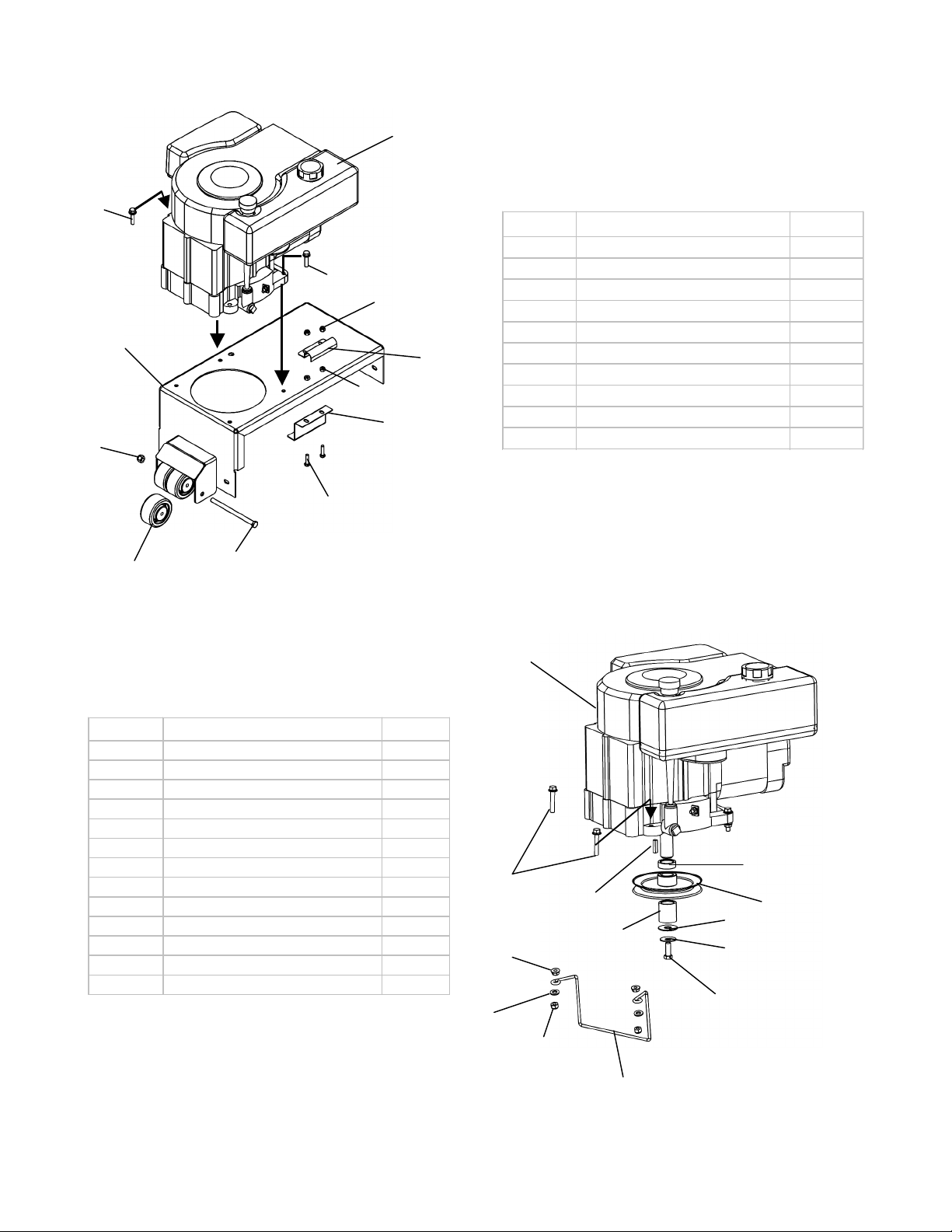
MOTOR BASE ASSEMBLY
ENGINE SET-UP
FIGURE 4
Item No. Description Part #
13 11- HP B&S Engine N/A
14 3/8-24 X 1 Engine Bolt Locktite NB-452N
15 Washer Belleville 699
16 1/4 X 1 Key Stock 9031
17 Engine Pulley- 5.5" 688
18 Engine Pulley Spacer Short 689S
19 Engine Pulley Spacer Long 689L
20 5/16-18 X 1-3/4 BOLT NB515
21 5/16 USS Washer NB556
22 5/16-18 Flge. Nut NB170
23 Belt Guide 6000
24 Washer TR150W
25 5/16-18 Nyloc Nut NB181
Figure 3
Item No. Description Part #
1 Motor Base 5102TK
2 Heat Shield 5094TK
3 Belt Guard 5097TK
4 Anti-Scalp Roller AS-001
5 3/8-16 X 5 1/2 GR5 ZP NB-575
6 3/8-16 Nyloc Nut NB-182
7 1/4-20 HX NUT NB-139
8 1/4-20 X 1 NB-102
9 1/4-20 Flange Nut NB-180
10 5/16-18 X 2 1/2 HCC GR5 ZP NB-253
See Detail
14
1
2
3
4
5
6
10
10
7
9
8
13
14
15
16
17
18
19
20
21
22
23
24
25
Page 15
15
15
Page 16

FIGURE 9
.Attaching unit to op erate in the front mount
position
(Quick Switch Mount kit sold separately)
Detail-1 , 3
Attachment Options
16
Detail-1
PART# 2646
Detail-3
PART# 9146
Item No. Description Part #
1 Mount Pin 5153TK
2 3/16 Click Pin NB506
3 3/4 ID Washer NB195
1
2
3
TM
Q uick Switch Mount kit
TM
Page 17

REPAIR PARTS
Your 50’’ T railmower has been produced wit h components designed specific t o
this machine. Alt hough standard V-belts, springs, bearings, blades, pulleys,
hardware, et c. look similar to parts used on ot her machinery, t hey may in some
cases be made of a different const ruction and/or materials.
17
Swisher products p ioneered tag along ty pe residential mowers in the 1980’s with its 40’’ Trailmower.
Today, Swisher offers a full line of products which include log sp litters, and a wide range of ATV
accessories.
? Did You Know ?
GENERAL MAINTANANCE / REPAIR LO G
Swisher ATV Quick Switch
System
Swisher Log Splitters
R
TM
R
Page 18

OWNER’S
MANUAL
MODEL NO.
Each mower has its own model number. Each engine has its
own model number. The model number for the mower will be
found on the right hand side of the drive belt housing. T he
model number for the engine will be found on the top of the
blower fan housing.
All mower parts listed herein may be ordered directly from
Swisher Mower & Machine Co., Inc. or your nearest Swisher
dealer.
All engine parts may be ordered from the nearest dealer of the
engine supplied with your mower.
WHEN ORDERING PARTS, PLEASE HAVE THE
FOLLOWING INFORMAT ION AVAILABLE:
* PRODUCT – 50” UNIVERSAL MOUNT
* SERIAL NUMBER - _______________
* MODEL NUMBER - _______________
* ENGINE MODEL NUMBER - _______________
TYPE - _______________
* PART NUMBER WIT H PAINT CODE
* PART DESCRIPTION
TELEPHONE - 1-800-222-8183
FAX - 1-660-747-8650
S WIS HER MOWER & MACHINE CO., INC.
1602 CORPORATE DRIVE
P.O. BOX 67
WARRENSBURG, M O 64093
SWISHER MOWER & MACHINE CO. ,INC.
PRINTED IN
50” UNIVERSAL MOUNT
TRAILMOWER
Visit us at: www.swisherinc.com
FT1150
R
 Loading...