

Page 1

swisherinc.com
OWNER’S
MANUAL
MODEL NO.
LS722H
STARTING SERIAL #:
L108-246001
LS728H
STARTING SERIAL #:
L108-246001
LS10528H
STARTING SERIAL #:
L108-246001
LS12534H
STARTING SERIAL #:
L108-246001
Model LS12534H Shown
LOG
LS12534H12V
STARTING SERIAL #:
L108-246001
SPLITTER
LS12534H12V-CA
STARTING SERIAL #:
L108-246001
LS12534H-CA
STARTING SERIAL #:
L108-246001
Safety
IMPORTANT
Read and follow all Safety
Precautions and Instructions
before operating this
equipment.
Rev. 08-253
1602 CORPORATE DRIVE, WARRENSBURG, MISSOURI 64093 PHONE 660-747-8183
Manufacturing quality lawn care equipment since 1945
Assembly
Operation
Service and Adjustment
Repair Parts
FAX 660-747-8650
Made In The
USA
12489
Page 2

LIMITED WARRANTY
The manufacturer’s warranty to the original consumer purchaser is: This product is free from defects in
materials and workmanship for a period of two (2) year from the date of purchase by the original consumer
purchaser. We will repair or replace, at our discretion, parts found to be defective due to materials or
workmanship. This warranty is subject to the following limitations and exclusions:
1) Engine Warranty All engines utilized on our products have a separate warranty extended
to them by the individual engine manufacturer. Any engine service
difficulty is the responsibility of the engine manufacturer and in no
way is Swisher Mower Co., Inc. or its agents responsible for the engine
warranty. The Briggs & Stratton Engine Service Hot-Line is 1-800233-3723. The Tecumseh Engine Service Hot-Line is 1-800-558-5402.
2) Commercial Use The warranty period for any product used for commercial or rental is
limited to ninety (90) days from the date of original purchase.
3) Limitation This warranty applies only to products which have been properly
assembled, adjusted, and operated in accordance with the instructions
contained within this manual. This warranty does not apply to any
product of Swisher Mower Co., Inc., that has been subject to alteration,
misuse, abuse, improper assembly or installation, shipping damage, or
to normal wear of product.
4) Exclusions Excluded from this warranty are normal wear, normal adjustments, and
normal maintenance. The pump, valve, and cylinder each carry separate
manufacture’s warranties. The valve and cylinder both carry a one (1) year
limited warranty. The pump carries a two (2) year limited warranty.
In the event you have a claim under this warranty, you must return the product to an authorized service dealer.
All transportation charges, damage, or loss incurred during transportation of parts submitted for replacement or
repair under this warranty shall be borne by the purchaser. Should you have any questions concerning this
warranty, please contact us toll-free at 1-800-222-8183. The model number, serial number, date of purchase,
and the name of the authorized Swisher dealer from whom you purchased the splitter will be needed before any
warranty claim can be processed.
THIS WARRANTY DOES NOT APPLY TO ANY INCIDENTAL OR CONSEQUENTIAL
DAMAGES AND ANY IMPLIED WARRANTIES ARE LIMITED TO THE SAME TIME PERIODS
STATED HEREIN FOR ALL EXPRESSED WARRANTIES. Some states do not allow the limitation of
consequential damages or limitations on how long an implied warranty may last, so the above limitations or
exclusions may not apply to you. This warranty gives you specific legal rights and you may have other rights,
which vary from state-to-state. This is a limited warranty as defined by the Magnuson-Moss Act of 1975.
TABLE OF CONTENTS
WARRANTY………………....….2
SAFETY..……………………….3-4
TOWING..….……..……………..5
OPERATION……………………6-8
MAINTENANCE.…………………….8
DECALS…..………….……………….9
PARTS BREAKDOWN…………….10-13
SPECIFICATIONS..…………………15
2
Page 3

SAFETY PRECAUTIONS
When you see this symbol, carefully read the message that follows and be
This Safety Alert Symbol indicates important messages in this manual.
alert to the possibility of personal injury.
Read this manual completely. This machine can amputate hands, feet, and throw objects.
Failure to observe the following safety instructions could result in serious injury or death.
WARNING:
to cause cancer, birth defects or other reproductive harm.
The engine exhaust from this product contains chemicals known to the state of California
DANGER: Your log splitter was built to be operated according to the rules for safe operation in this
manual. As with any type of power equipment, carelessness or error on the part of the operator can result
in serious injury. If you violate any of these rules, you may cause serious injury to yourself or others.
•
Read and understand the manual. Learn to operate this equipment in a safe manner. Familiarize
yourself with all of the controls in a safe environment before starting to work with this machine.
•
DO NOT under any circumstances alter this log splitter. This equipment was designed and
engineered in accordance with operating instructions. Altering this equipment, or using this
equipment in such a way as to circumvent its design capabilities and capacities, could result in
serious injury or fatality and WILL VOID THE WARRANTY.
•
Allow ONLY responsible adults who have read this manual to operate this machine. NEVER
allow children to operate this machine.
•
NEVER operate or allow someone to operate this equipment while under the influence of
alcohol, drugs or medication. Being coherent is essential for safety.
• ALWAYS use outdoors with adequate ventilation. DON’T run the engine in an enclosed area.
Exhaust gases contain carbon monoxide. This odorless gas can be deadly when inhaled.
•
NEVER use splitter for any other purpose than splitting wood. Any other use can result in
injury. Your splitter is a precision piece of power equipment, not a toy. Therefore, exercise
extreme caution at all times.
• ONLY a single operator is to load and operate the log splitter. KEEP all others, including pets
and children, a minimum of 20 feet away from your work area. More accidents occur when
more than one person operates the log splitter than any other time.
• ALWAYS wear protective gear such as safety goggles, protective hearing device, steel-toed
shoes, and tight-fitting gloves without drawstrings or loose cuffs.
•
NEVER wear loose clothing or jewelry that can be caught by moving parts of the splitter and
pull you into it. Keep hair away from moving parts.
• NEVER operate your splitter on wet, muddy, or icy surfaces. KEEP work area clean of split
wood. Safe footing is essential in preventing accidents.
• ONLY operate splitter on level ground with wheels blocked, not on the side of a hill. It could
tip, or rolling logs, poor footing, etc. could cause an accident.
3
Page 4

•
NEVER operate your splitter near a flame or spark. Hydraulic oil and gasoline are flammable and can
explode.
•
NEVER fill gas tank while the engine is hot or running. Allow the engine to cool before refueling.
•
This unit is equipped with an internal combustion engine and should not be used on or near any
unimproved forest-covered, brush-covered or grass-covered land unless the engine’s exhaust system is
equipped with a spark arrester meeting applicable local or state laws (if any). If a spark arrester is used it
should be maintained in effective working order by the operator.
-NOTE-
In the state of California, the above is required by law (Section 442 of the California Public Resources Code).
Other states may have similar laws. Federal laws apply on federal lands. A spark arrester muffler (optional by
manufacturer) is available at your nearest engine dealer. Check legal requirements in your area.
• ONLY use your hands to operate the control lever. NEVER use foot, knee, rope or any extension device.
• Split ONLY one log at a time. NEVER attempt to split two logs on top of each other.
• NEVER place hands or feet between log and splitting wedge or between log and ram during forward or
reverse stroke. ALWAYS keep fingers clear of splits that open in log during splitting operation.
• DO NOT straddle or reach across the splitting area while operating the splitter.
• DO NOT step over splitter when the engine is running. You may trip or accidentally activate the splitting
wedge. Walk around to get to the other side.
•
NEVER attempt to load splitter while splitting wedge is in motion. When loading log splitter, place hands
on the sides of the log, not the ends.
•
NEVER attempt to split woods across the grain. Wood may burst or fly out of your splitter and result in
serious injury.
• NEVER leave your splitter unattended with the engine running. Shut off the engine if you are leaving
your splitter, even for a short period of time. Someone could accidentally activate the ram and be injured.
• Both ends of the log should be cut as squarely as possible to prevent the log from sliding out of the splitter
during operation. Log length should be kept to 24” or less.
•
NEVER operate your splitter while it is attached to the tow vehicle.
•
BEFORE towing, be certain that the splitter is securely attached to the towing vehicle and that the support
leg, beam and cylinder are secured in there respective towing positions.
•
NEVER allow persons to ride on splitter. DO NOT carry any cargo or wood on your splitter. It may fall
off and cause an accident.
•
DO NOT loosen or remove any hydraulic fitting, line or reservoir cap while your splitter or engine is
running.
• Fluid escaping from a very small hole can almost be invisible. DO NOT check for leaks with your hand.
See maintenance section for instructions.
infection or reaction can develop if proper medical treatment is not administered immediately.
•
DO NOT operate your splitter in poor mechanical condition or when it is need of repair.
•
ALWAYS disconnect the spark plug wire and place the wire where it cannot contact the spark plug, to
prevent accidental starting the engine when setting up, transporting, adjusting or repairing.
IF injured by escaping fluid, see a doctor at once. Serious
4
Page 5
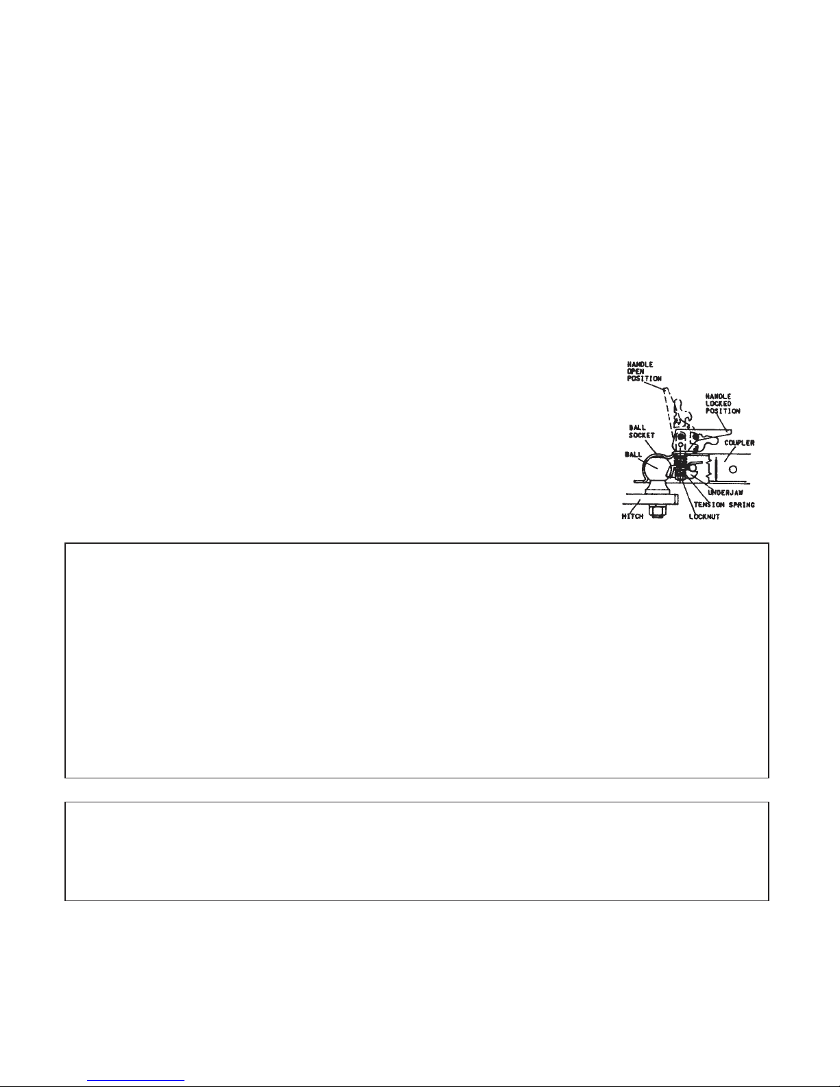
WHEN BALL IS COMPLETELY NESTED IN BALL SOCKET, ROTATE COUPLER HANDLE
TIGHTNESS BEFORE TOWING. BE SURE COUPLER HANDLE IS IN LOCKED POSITION.
NEVER EXCEED WEIGHT CAPACITY AND ALWAYS USE SAFETY CHAINS. ALWAYS USE
TOWING SAFETY
• Do not allow persons to ride on splitter. Do not carry any cargo or wood on your
splitter. It may fall off and endanger vehicles that are following you.
• Be sure support leg is in the travel position and coupling secure. This must also
be retracted so not to interfere while towing. Retract support leg by removing
pin, pivoting up, and replacing pin.
• Never exceed 45 MPH while towing your splitter. Be extra cautious when
traveling over rough terrain, especially over railroad tracks.
• Always be careful while backing your splitter. You
splitter if not careful.
• Before using splitter, disconnect it from tow vehicle. A log could easily be
pushed forward into the vehicle.
• See tire and wheel specifications for PSI while towing.
• Be aware of the extra length of splitter while turning, parking, crossing
intersections, and in all driving situations.
•
ADJUST COUPLER LOCKING PRESSURE ON BALL BEFORE USE. PLACE HANDLE IN LOCKED
POSITION WITH BALL IN COUPLER. TIGHTEN LOCKNUT AGAINST TENSION SPRING SO THAT
COUPLER IS NOT LOOSE ON BALL. CORRECT ADJUSTMENT WILL ALLOW HANDLE TO BE
RELEASED WITH MODERATE PRESSURE APPLIED TO HANDLE.
TO OPEN, PULL UP ON COUPLER HANDLE AND ROTATE FORWARD. PLACE COUPLER ON BALL
OPERATION INSTRUCTIONS
POSI-LOCK COUPLER
BACKWARD UNTIL HANDLE IS IN LOCKED POSITION.
AFTER TOWING FOR 50 MILES, CHECK COUPLER FOR TIGHTNESS ON BALL. ALWAYS CHECK
could jackknife your log
WARNING:
CORRECT BALL SIZE, MAKING SURE BALL IS COMPLETELY INSERTED INTO COUPLER. LOCK
COUPLER HANDLE SECURELY BEFORE TOWING. ALWAYS CHECK FOR DAMAGES AND
REPLACE IF DAMAGED. AVOID SHARP TURNS AND STEEP VERTICAL ANGLES WHEN TOWING.
5
Page 6

ASSEMBLY
This log splitter has been partially assembled at the factory. Refer to the drawings and part lists should it become
necessary to disassemble the unit for repair or replacement of parts.
Inspect all components for damage. If you believe you have a damaged part please contact customer service
immediately at 1-800-222-8183.
WARNING: Exercise extreme caution, as parts are very heavy. Sufficient persons or mechanical handling
equipment should be used.
Refer to uncrating and assembly instructions for assembly procedures.
OPERATION
INTENDED USE: This log splitter is intended and designed to only split wood. NEVER use for any other
purposes. Doing so can cause injury or VOID THE WARRANTY.
IMPORTANT: This unit is shipped with oil but without gasoline in the engine. After assembly, see separate
Engine Manual for proper fuel and oil recommendations.
WARNING: DO NOT START OR RUN THE LOG SPLITTER WITHOUT OIL IN THE ENGINE AND
HYDRAULIC RESERVOIR.
FILLING THE HYDRAULIC RESERVOIR
Fill the hydraulic reservoir to the top mark on the dipstick with Dexron III / Mercon III automatic transmission
fluid, a 10W AW hydraulic fluid or Pro-Mix AW-32 Hydraulic oil. After the hydraulic reservoir and the engine
crankcase are filled correctly with their respective oils, start the engine. Remember to set the throttle and turn on
the fuel shut-off valve. The hydraulic pump should prime itself. With the engine running, move the hydraulic
valve lever toward the wedge. This will cause the cylinder to extend and expel air. When the cylinder is fully
extended, retract it. Repeat this procedure several times. (An erratic movement of the cylinder and wedge indicates
that there is air in the system). Once the cylinder has a smooth and constant speed indicating that all air has been
expelled, shut the system off and refill the reservoir until the fluid is in the safe operating range as specified by the
marks on the dipstick.
START UP
WARNING:
AND HYDRAULIC RESERVOIR.
See separate Engine Manual for fuel and oil recommendations. If applicable your log splitter has come equipped
with a fuel shut-off valve for towing purposes.
Before starting engine make sure crankcase is filled correctly with oil and the proper fuel has been used. The
engine will only start when the throttle lever and fuel shut-off valve if applicable are turned to their ON positions.
STARTING INSTRUCTIONS
1. Move throttle control to “FAST.”
2. Set Choke to on position (if applicable) or push primer bulb three (3) times. NOTE: Do not use primer or
3. Grasp rope handle and pull out slowly until resistance it felt. Then pull rapidly with a full arm stroke.
4. When Engine starts, set choke to off position (if applicable) leave throttle control at “FAST.” The throttle
5. To stop engine, move throttle lever to “SLOW” for a few seconds then to “STOP.”
DO NOT START OR RUN THE LOG SPLITTER WITHOUT OIL IN THE ENGINE
choke to restart a warm engine after a short shutdown.
NOTE: If engine fails to start after three (3) pulls, repeat steps 1 and 2.
must be set in the fast position for maximum performance.
6
Page 7

COLD WEATHER START UP
thickened hydraulic fluid. Simply pull the handle out into locked position. Start engine, let it warm up,
long as the towed equipment does not visibly impair the tow vehicle taillights. This is based on a state,
to state requirements. The customer is responsible for meeting the states requirements.
IF injured by escaping fluid, see a doctor at once. Serious infection or reaction can develop if
The Cold Weather Clutch enables the engine to be started without having to pull through cold,
and release Cold Weather Clutch. After starting, assure that the lever has reengaged.
SPLITTER OPERATION
1. Set up the log splitter in a clear, level area and block the wheels. The suction port on the tank should
always be on the lower side of the log splitter.
2. Place a log on the beam, against the foot plate. Make sure the log is securely on the foot plate and up
against the beam.
3. Depress the valve lever so that the cylinder will drive the push block into the log. Extend the cylinder
until the log splits or to the end of its stroke. If the log has not completely split after the cylinder has
reached the end of its extension, retract the cylinder. NOTE: Leaving the valve in the “actuate” position
at the end of the stroke may damage the pump. Always use extra care when splitting logs with ends that
are not square.
NOTE:
To extend the life of the hydraulic cylinder, avoid “BOTTOMING OUT” the cylinder.
TOWING SAFETY
This unit should not be towed on any street, highway, or public road without checking the existing federal, local,
and state laws. Any licensing or modifications such as taillights, etc., need to comply with existing federal, local,
or state vehicle requirements is the sole responsibility of the purchaser. Obey all regulations when towing on
public roads and highways. See also
SAFETY PERCAUTIONS.
Turn the fuel shut-off valve if applicable OFF to prevent flooding of the engine while traveling.
Be careful when backing up. You can easily jack-knife your splitter.
TOWING AT NIGHT
The requirements for taillights are based on States regulations. Some states allow towing at night as
If a “Statement of Origin” is required in your state, see your local dealer to receive one.
HYDRAULIC SAFETY
The hydraulic system on your splitter requires careful inspection along with the mechanical parts. Be sure to
replace any frayed, kinked, cracked or otherwise damaged hydraulic components. Just because it isn’t leaking
today doesn’t mean that it will not fail tomorrow.
Fluid escaping from a very small hole can almost be invisible. Do not check for leaks with your hand. Escaping
fluid under pressure can have sufficient force to penetrate skin causing serious personal injury or even death.
Leaks can be detected by passing a piece of cardboard or wood over the suspected leak and looking for
discoloration.
proper medical treatment is not administered immediately.
Should it become necessary to loosen or remove any hydraulic fittings, lines or reservoir cap, be sure to relieve all
pressure by shutting of the engine and moving the control handle back and forth several times.
NEVER remove the cap from the hydraulic tank or reservoir while the unit is running. Hot oil under pressure
could result in serious injury. See also
The pressure relief valve on your splitter is preset at the factory. DO NOT adjust the valve. Only a qualified
technician should perform this adjustment.
SAFETY PERCAUTIONS.
7
Page 8

MAINTENANCE AND STORAGE
your splitter.
be made of a different construction and/or materials. All replacement parts must meet manufacturer’s
WARNING:
Consult the operating and maintenance instructions of the engine manufacturer for engine care.
Always check the oil level of the hydraulic reservoir before operation. Operating without an adequate oil
supply will cause severe damage to the pump. Change the hydraulic fluid in the reservoir after every 100 hours of
operation. Change the hydraulic filter after every 50 hours of operation (use only a 10 micron hydraulic filter).
Periodically check that all nuts, bolts, screws, clamps and fittings are tight and secure.
To keep your splitter in top working condition perform all recommended maintenance procedures before you use
If the wedge becomes dull or nicked a grinder or sharpening tool can be used to sharpen it.
Completely drain the fuel tank prior to storage. Always store gasoline in an approved, tightly sealed container. Store
container in a dry, cool place with adequate ventilation. Keep fuel away from areas where fumes could contact open
flame, pilot light or sparks.
Be aware of the environment when disposing of used petroleum products. Please dispose of used hydraulic
fluid, engine oil and any by products from the maintenance of your splitter at approved recycling centers.
Should it become necessary to disassemble the unit for repair or replacement of parts, refer to the drawings and parts
list on the following pages. Exercise extreme caution, as some parts are very heavy and will require sufficient
persons or mechanical handling equipment.
Your Swisher Log Splitter has been produced with components designed specifically to this machine. Although
standard springs, hardware and ect may look similar to parts used on other machinery, they may in some cases
DISCONNECT THE SPARK PLUG BEFORE PERFORMING ANY MAINTENANCE.
specifications.
The operation of any splitter can produce foreign objects to be thrown into the
eyes, resulting in severe eye damage. Always wear certified safety glasses or
wide-vision safety goggles over spectacles before staring any splitting machine
and while operating such a machine.
The operation of any splitter produces sound waves that are damaging to the
human ear. Ear protection is recommended.
8
Page 9

SAFETY DECALS
Replace decals immediately if damaged.
OD16 – FUEL SHUT OFF DECAL 12493 – COLD WEATHER DECAL
12494 – HYDRAULIC FILL PLUG
DECAL
12532 – HYDRAULIC OIL DECAL
12492 – OPERATOR INSTRUCTION
12549 – DO NOT EXCEED 45 MPH
DECAL
DECAL
11427 – DANGER DECAL
9
Page 10

LS722H, LS728H, LS10528H & LS12534B
Model LS12534B12V Shown
ASSEMBLY DETAIL
MODELS
10
Page 11

SERVICE PARTS
Please have Model and Serial Numbers ready when ordering parts.
Color cannot be guaranteed upon service parts.
ITEM NUMBER DESCRIPTION PART NUMBER
1 Motor Base/Hydraulic Tank 12350TK
2 36" Suction Hose 12362
3 #12 Hose Clamp LS5001
Not Shown Filter Head LS1112
Not Shown Filter Element LS1113
Not Shown Return Line Fitting 7329
7 Breather Cap 12379
8 Bearing Seal 2203S
9 Tapered Bearing 2203B
10 Tire & Wheel 7296
11 Nut - Nyloc Jam, 1/2-13 ZY NB688
12 Castle Nut 2203CN
13 Cotter Pin NB633
14 Wheel Dust Cover 2203DC
15 High Pressure Hose 48" 15149
16 Bolt 3/8-16 X 1 1/2 GR 5 NB107
17 Washer 3/8 SAE NB272
18 Idler Bushing 6037
20 Nut 3/8-16 Nyloc NB182
21 Bolt 3/8-16 X 2 1/2 GR 5 NB619
22 Idler Arm 6041TK
23 Idler Pulley B527
24 Nut 3/8-16 2-Way Lock NB280
25 Clutch Lever 11226TK
26 Clutch Lever Cap 2077
27 Wire Link For Idler Arm BRS6H
28 Idler Tension Spring - Bent Leg 4422
29 Bolt Spade 5/16-18 X 12 10636YZ
30 Nut 5/16-18 Nyloc NB181
31 Return Hose 72" 12363
32 #16 Hose Clamp LS4999
33 Bolt - 1/2-13 X 6 HCC GR5 ZP NB151
34 Nut - Nyloc 1/2-13 ZY Standard Pattern NB688
Not Shown Grommet 12441
Not Shown 44" Belt 644
PUMP DETAIL
ALL MODELS
ITEM # DESCRIPTION PART #
1
2
3 #16 Hose Clamp LS4999
4 36" Suction Hose 12362
5 Pump Pulley 7306
6 1/8 X 1/2 #3 Woodruff Key 024002
7 5/16-18 X 1/2 Set Screw w/Loctite NB312
8 Bolt 5/16-18 X 3/4 Serr. Flange NB596
9 Nut 5/16-18 Serr. Flange NB170
Hydraulic Pump - Model LS722H & LS728H 12360
Hydraulic Pump - Model LS10528H, LS12534H &
LS12534H12V LS2002B
11
B
B
Note: Install pulley collar up and bottom side
of pulley flush with end of pump shaft.
Page 12

Wedge Weldment 14622TK Shown
ITEM NUMBER DESCRIPTION PART NUMBER
1
2
3
4 Thin GIB Plate (All 34 Ton Models) 7388TK
5
6 1/2-13 X 2 1/2 GR5 Carriage Bolt NB643
7 1/2 Lock Washer NB508
8 1/2-13 Nut NB213Z
9 Bolt - 1/2-13 X 3 1/4 GR8 Alloy ZY 12669
10 Washer TR150W
11 Nut 1/2-13 Nyloc Jam NB121
12
13 Steel Pin 7293
14 Clip Pin NB642
15 Hydraulic Fitting 7291
16 Stationary Line Assembly 7288TK
17 2-Way Pipe Nipple 7292
18 Return Line Fitting 7329
19 Valve Control 7287TK
21 Valve Control Handle 7423
23 Master Chain Link 7424
24 Saftey Hitch Pin NB522
25 Pin - Cotter, 1/8 X 2 NB633
26 Washer - USS Flat, 1/2 ZY NB555
24
Beam Weldment 14900TC Shown
BEAM DETAIL ALL MODELS
NOT ALL PARTS ARE ON ALL MODELS
Beam Weldment - Model LS722H, LS728H & LS10528H 14900TC
Beam Weldment - Model LS12534H & LS12534H12V 12440TC
Eight BoltWedge Weldment (All 34 Ton Models) 7233TK
Six bolt Wedge Weldment- Model LS722H, LS728H, & LS10528H 14622TK
Spacer - Wedge 14619TK
Thick GIB Plate (All 34 Ton Models) 7237TK
Plate - Bottom Wedge 14620TK
Bottom GIB Plate (All 34 Ton Models) 7333TK
Ram Cylinder - Model LS722H 7284TK
Ram Cylinder - Model LS728H & LS10528H 7354TK
Ram Cylinder - Model LS12534H & LS12534H12V 7355TK
12
Page 13

ITEM NUMBER DESCRIPTION PART NUMBER
1 Tongue Tube 12346TK
2 2" Ball Coupler 7365
3 Folding Support Leg 14924TK
4 Safety Chain w/Hook 7366
5 Bolt 3/8-16 X 4 GR5 NB645
6 Bolt 3/8-16 X 3 1/2 GR5 NB649
7 Bolt 3/8-16 X 3 GR5 NB150
8 Latch Pin Guide Bushing 7840Z
9 Washer Fender 3/8 10177
10 Washer SAE 3/8 NB272
11 Nut 3/8-16 Nyloc NB182
12 1/2 X 3 Bent Pin w/Hair Pin NB606
TONGUE DETAIL
ALL MODELS
13
Page 14

ENGINE DETAIL
1
MODEL LS10528H, LS12534H &
LS12534H12V
ITEM # DESCRIPTION PART #
1 Engine N/A
2
3 Nut 5/16-18 Serr. Flange NB170
4 Upper Spacer 689S
5 Engine Pulley BB105
6 Lower Spacer 689L
7 Washer TR150W
8 Washer Belleville 699
9 Bolt 7/16-20 X 1 GR 5 w/Loctite NB452N
10 1/4 X 1 Keystock 9031
NOTSHOWN Fuel Shut Off Valve (Inline) 7414
NOTSHOWN Fuel Line Clamp 6FLC
Bolt 5/16-18 X 1 3/4 Serr. Flange (One Per - 12 Volt Engines) NB515
Bolt 5/16-18 X 1 1/4 Serr. Flange NB253
2
4
3
5
6
7
10
8
9
Note: Install pulley collar up and bottom side
of pulley flush with end of engine shaft.
ENGINE DETAIL
MODEL LS722H & LS728H
ITEM # DESCRIPTION PART #
1 Engine N/A
2 Bolt 5/16-18 X 1 1/4 Serr. Flange NB253
3 Bolt 5/16-18 X 2 1/4 Serr. Flange NB622
4 Nut 5/16-18 Serr. Flange NB170
5 3/16 X 1 Keystock 9030
6 Engine Pulley 7/8" ID 7323
7 5/16-18 X 1/2 Set Screw w/Loctite NB312
8 Washer Belleville 699
9 Bolt 3/8-24 X 1 w/Loctite NB238N
NOTSHOWN Fuel Shut Off Valve (Inline) 7414
NOTSHOWN Fuel Line Clamp 6FLC
14
Page 15

12 Volt Accessories12 Volt Accessories
4
BATTERY
3
2
5
6
ITEM # DESCRIPTION PART #
1 Throttle & Key Switch Bracket 12491TK
2 Throttle Cable 686N
3 Throttle Knob 686K
4 Battery Hold Down Strap 12498TK
5 Nut 1/4-20 Nyloc NB180
NOT SHOWN Washer 1/4 SAE NB274
6 Bolt 1/4-20 X 7 NB732
7 Solenoid Bracket 9913TK
8 Bolt 5/16-18 X 3/4 NB143
NOT SHOWN Nut 5/16-18 Serr Flange NB170
9 Bolt 1/4-20 Serr Flange NB109
NOT SHOWN Nut 1/4-20 Serr Flange NB524
10 Key Switch 3623
NOT SHOWN Wiring Harness 12551
NOT SHOWN Solenoid Assembly 1002004
NOT SHOWN Nut - 1/4-20 Kep NB203
NOT SHOWN Nut - 1/4-20 Nyloc NB180
NOT SHOWN Cable - Battery 19 1/2"or 20" Red BCL
NOT SHOWN Boot - Rubber, Small, Battery Cable BCBT
NOT SHOWN Cable - Battery 19 1/2"or 20" Black BCLB
7
8
9
1
10
Wiring Diagram
15
Page 16

Idler Pulley
Cylinder rod will not extend
erratic while extending and
Pump Pulley
Engine Pulley
BELT ROUTING DIAGRAM
(VIEWED FROM UNDERSIDE OF SPLITTER)
TROUBLESHOOTING
Problem Cause Remedy
Engine fails to start. 1. Spark plug wire disconnected. 1. Connect wire to spark plug.
2. Fuel tank not full enough or stale fuel. 2. Fill tank full with clean, fresh gasoline.
Engine is hard to start or
runs erratic.
3. Throttle control lever not in correct
starting position.
4. Choke not in CHOKE position. 4. Move choke to CHOKE position.
5. Engine not primed properly. 5. Prime engine.
6. Fuel valve not ON or blocked fuel line. 6. Turn on fuel valve or clean fuel line.
7. Faulty spark plug. 7. Clean, adjust gap, or replace spark plug.
1. Spark plug wire loose. 1. Connect and tighten spark plug wire.
2. Unit running on CHOKE. 2. Move choke lever to OFF position.
3. Blocked fuel line or stale fuel. 3. Clean fuel line; fill tank with clean, fresh
4. Water or dirt in fuel system. 4. Drain fuel tank. Refill with fresh gasoline.
5. Dirty air cleaner. 5. Clean or replace air cleaner.
6. Carburetor out of adjustment. 6. See authorized service center.
3. Move throttle lever to FAST position.
gasoline
or contract. 1. Cold weather clutch not engaged. 1. Engage cold weather clutch.
2. Broken or improperly installed belt. 2. Replace or reinstall belt.
3. Low hydraulic fluid. 3. Fill hydraulic tank to correct fluid level.
4. Hydraulic lines blocked. 4. Flush and clean hydrualic system.*
5. Damaged or broken pump. 5. See authorized service center.
6. Damaged control valve. 6. See authorized service center.
Cylinder rod is slow or
contracting.
1. Low hydraulic fluid. 1. Fill hydraulic tank to correct fluid level.
2. Contaminated hydraulic fluid. 2. Drain fluid, flush system, and refill.
3. Excessive pump inlet vacuum. 3. Make certain pump hoses are clear and
4. Damaged pump. 4. See authorized service center.
5. Damaged control valve. 5. See authorized service center.
6. Internal cylinder damage. 6. See authorized service center.
unblocked. Make certain hose in not
collapsing under suction.
16
Page 17

TROUBLESHOOTING CONTINUED
Problem Cause Remedy
Leaking Cylinder 1. Broken seals. 1. See authorized service center.
2. Scored cylinder. 2. See authorized service center.
12 Volt Units
Engine will not turn over 1. Weak or dead battery. 1. Recharge or replace battery.
2. Blown fuse. 2. Replace fuse.
3. Corroded battery terminals. 3. Clean battery terminals.
4. Loose or damaged wiring. 4. Check all wiring.
5. Faulty ignition switch. 5. Check/replace ignition switch.
6. Faulty solenoid. 6. Check/replace solenoid
Engine clicks but will
not start 1. Weak or dead battery. 1. Recharge or replace battery.
2. Corroded battery terminals. 2. Clean battery terminals.
3. Loose or damaged wiring. 3. Check all wiring.
4. Faulty solenoid. 4. Check/replace solenoid.
Battery will not charge 1. Bad battery. 1. Replace battery.
2. Corroded battery terminals. 2. Clean battery terminals.
3. Faulty solenoid. 3. Check/replace solenoid.
4. Bad alternator. 4. See authorized service center.
NOTE: For repairs beyond those listed here, contact your nearest authorized service center.
* Flushing the reservoir tank and hoses with kerosene whenever service is performed on the tank, hydraulic pump or
valve is recommended. Contact an authorized service center.
MAINTENANCE LOG
Date of Service Service Performed
Notes
17
Page 18

12.5 HP Briggs and Stratton I/C
SPECIFICATIONS
Models
LS722H LS728H LS10528H LS12534H & LS12534H12V
Splitting Force
Engine
Splitting Positions
Cylinder Size
Pump
Pump Specs
Valve
Drive System
Hydraulic System Fluid
Capacity
Maximum Log length
Tire Specs
22 Tons 28 Tons 28 Tons 34 Tons
7 HP Briggs and Stratton
Quantum
Horizontal and Vertical Horizontal and Vertical Horizontal and Vertical Horizontal and Vertical
4" X 24" 4 1/2" X 24" 4 1/2" X 24" 5" X 24"
2 Stage with Heavy Duty
Bearings
11 Gallons Per Minute 11 Gallons Per Minute 16 Gallons Per Minute 16 Gallons Per Minute
Auto Return Auto Return Auto Return Auto Return
Belt Drive 1:1 Ratio with
Clutch for Easy Starting
18-22 Quarts 19-23 Quarts 19-23 Quarts 20-24 Quarts
25 1/2" 25 1/2" 25 1/2" 25 1/2"
4.00 X 4.80 X 8 with High
Speed Bearings
7 HP Briggs and Stratton
INTEK
2 Stage with Heavy Duty
Bearings
Belt Drive 1:1 Ratio with
Clutch for Easy Starting
4.00 X 4.80 X 8 with High
Speed Bearings
10.5 HP Briggs and
Stratton I/C
2 Stage with Heavy Duty
Bearings
Belt Drive 1:1 Ratio with
Clutch for Easy Starting
4.00 X 4.80 X 8 with High
Speed Bearings
(12 volt Start on 12V Model)
2 Stage with Heavy Duty Bearings
Belt Drive 1:1 Ratio with Clutch for
Easy Starting
4.00 X 4.80 X 8 with High Speed
Bearings
Metal Fenders
Ball Hitch
Unit Weight
No No No No
2" Ball 2" Ball 2" Ball 2" Ball
525 Lbs 540 Lbs 640 Lbs 660 Lbs
NOTES
:
18
Page 19

SWISHER HISTORY
Back before electricity came to rural Missouri Max Swisher was producing lawn mowers
from his mother’s chicken house. Max never liked to mow grass. He installed a
gearbox on his family’s lawn mower creating a self-propelled unit. By tying one end of a
rope to the mower and the other end to a tree in the center of the yard the mower
circled the tree, shortening the rope and guiding the mower in concentric circles. Max
enjoyed relaxing under a shade tree while his invention did all the work.
Max had designed his first self-propelled rotary lawn mower to do his dirty work for him.
Neighbors noticed his new invention and began asking him to make more. Today, 60
years later, Swisher Mower and Machine Company, Inc. is still producing innovative
lawn and garden and ATV/UTV equipment designed to give us all more “relaxing in the
shade” time.
Swisher products have been featured nationally on television programs such as Regis
and Kathie Lee and seen in publications like ATV Magazine
Mechanics Magazine and others. In January 2000 Popular Mechanics Magazine
named Max’s zero turning radius riding mower one of the 20thcentury’s top household
inventions.
, Country Journal, Popular
Swisher offers value and function in its products to meet your grounds maintenance
needs.
CELEBRATING OVER 60 YEARS OF INNOVATION
SINCE 1945
19
Page 20

OWNER’S
LOG SPLITTER
MANUAL
MODEL NO.
LS722H
LS728H
LS10528H
LS12534H
LS12534H12V
LS12534H12V-CA
LS12534H-CA
HOW TO ORDER
REPAIR PARTS:
Each Log Splitter has its own serial number. Each engine has
its own serial number. The serial number for the Log Splitter
will be found on the right hand side of the hydraulic oil
reservoir. The serial number for the engine will be found on
the top of the blower fan housing.
All Log Splitter parts listed herein may be ordered directly
from Swisher Mower & Machine Co. Inc., your nearest
Swisher dealer, or from our website.
All engine parts may be ordered from the nearest dealer of the
engine supplied with your log splitter. Parts subject to change
without notice.
WHEN ORDERING PARTS, PLEASE HAVE THE
FOLLOWING INFORMATION AVAILABLE:
* PRODUCT – SWISHER LOG SPLITTER
* SERIAL NUMBER - _______________
* MODEL NUMBER - _______________
* ENGINE MODEL NUMBER - _______________
TYPE - _______________
* PART NUMBER
* PART DESCRIPTION
SWISHER MOWER & MACHINE CO. INC.
www.swisherinc.com
TELEPHONE - 1-800-222-8183
FAX - 1-660-747-8650
SWISHER MOWER & MACHINE CO. INC.
1602 CORPORATE DRIVE
WARRENSBURG, MO 64093
 Loading...