

Page 1
MANUFACTURING QUALITY LAWN CARE EQUIPMENT SINCE 1945
Owner’s
Manual
GC-14
IMPORTANT
Read and follow all
Safety Precautions
and Instructions
Before Operating this
Equipment.
14 Cubic Ft.
Garden Cart
1602 CORPORATE DRIVE, PO BOX 67, WARRENSBURG, MISSOURI 64093
11621 REV. 05-269
Made In CHINA
PH 660. 747. 8183 FAX 660. 747. 8650
swisherinc.com
Page 2
RULES FOR SAFE OPERATION
package with parts as shown in the chart below
ASSEMBLY INSTRUCTIONS
Preventing accidents is the responsibility of every TOOLS REQUIRED
equipment operator. The following general safety (1) Screw Driver
precautions must be fully understood and followed (1) Pliers
by every operator. (1)10mm Wrench
1. Do not at any time carry passengers in this cart. It
is designed for carrying materials only and not When assembling your cart, place the heads of all
intended to carry passengers. screws to the inside and hex nuts with flat washers
2. Be careful on any grade (hill) and stay off of steep to the outside.
grades.
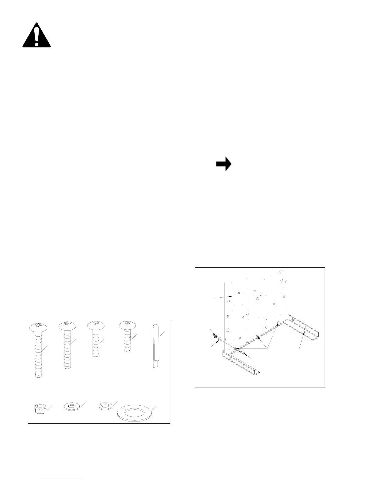
3. Use caution when loading cart to avoid tipping. 1. Lay the front angle assembly down (flat) on floor
4. Avoid large holes and ditches when transporting and stand the bottom panel in position as shown in
loads. figure 2.
Your Farm/Yard Cart carton contains a hardware
NOTE
The bottom panel has one galvanized
and in figure 1.
edge; this is the rear. The front edge
has three holes. See figure 2.
Contents of Hardware Pack: (See figure 1)
REF. QTY. DESCRIPTION
A 6 Screws,M6X50 2. Line up three holes in bottom panel with holes in
B 2 Screws,M6X40 front angle assembly. Start three M6X25 screws
C 8 Screws,M6X30 through bottom panel, then through angle. Secure
D 21 Screws,M6X25 screws with flat washers and hex nuts.
E 4 Cotter Pins
Finger tight at this time.
See figure 2.
F 37 Hex Nuts,M6
G 33 Flat Washer,Ф6
H 4 Lock Washer,Ф6
I 4 Large Flat Washer
BOTTOM
PANEL
HARDWARE REFERENCE CHART
B
A
M6X40
C
M6X25
M6X30
D
E
M6
HEX
NUT
Ф
6
FLAT
WASHER
M6X25
SCREW
THREE
HOLES
FRONT
EDGE
Make only
FRONT
ANGLE
ASSEMBLY
M6X50
F
G
H
FIGURE 1
I
FIGURE 2
2
Page 3
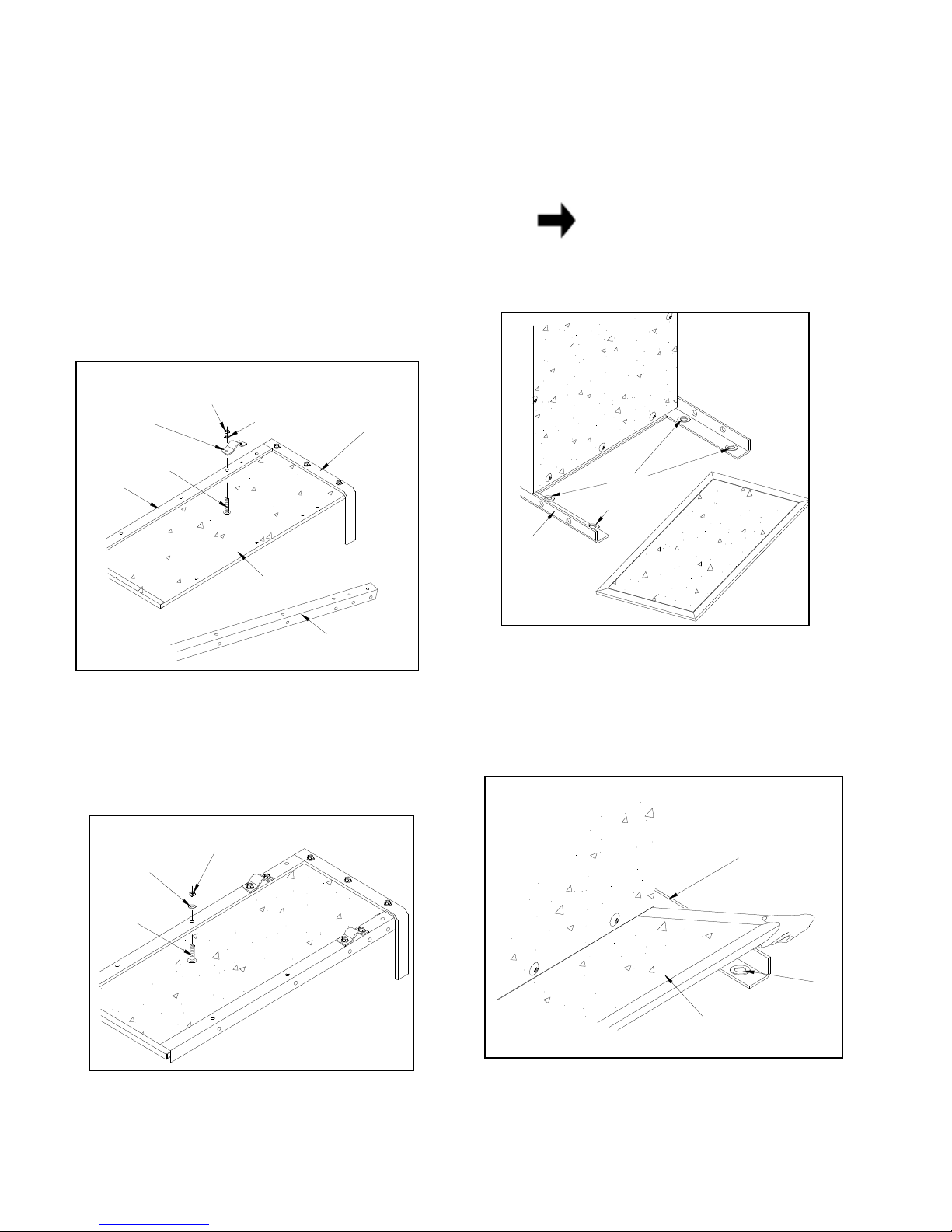
3. Turn the front angle assembly and bottom panel 7. Stand the cart on end with the front angle assemupside down as shown in figure 3. bly down on the floor. Temporarily place the four
large flat washers (axle washers) on
4. Lay each side angle on the bottom panel so that the inside of front angle assembly. See figure 5.
the two holes (for the axle clamp) are closer to the
front angle assembly. See figure 3.
NOTE
These washers act as shims and are
5. Secure both axle clamps to the side angles and
the bottom panel using four M6X30 screws,
lock washers and hex nuts.
until the axle is assembled. See figure 3.
tight
M6
HEX
NUT
SIDE
ANGLE
AXLE
CLAMP
M6X30
SCREW
Make only finger
Ф
6
LOCK
WASHER
FRONT
ANGLE
ASS'Y
just for assembly purposes. You will
remove them later to use on axle.
BOTTOM
PANEL
LARGE
FLAT
WASHER
FRONT
ANGLE
BOTTOM
PANEL
SIDE
ANGLE
ASS'Y
FIGURE 5
8. Lay the front panel down onto the front angle
FIGURE 3
assembly, on top of the four large washers.
6. Assemble four M6X25 screws, flat washers and See figure 6.
hex nuts to the side angles and bottom panel
using the holes on each side of the axle clamps.
Tighten the four nuts.
Ф
6
FLAT
WASHER
M6X25
SCREW
See figure 4.
M6
HEX
NUT
FRONT
PANEL
FRONT
PANEL
FRONT
ANGLE
ASS'Y
LARGE
FLAT
WASHER
FIGURE 4 FIGURE 6
3
Page 4

9.Position a Side Panel againist a Side Angle,resting
WASHERS
FRONT
HOLE
it down on top of the front panel. Place a support
strap on the outside of the side angle and start a
M6X30 screw through the
second hole
side panel, the side angle and the support strap.
Secure with a flat washer and hex nut.
finger tight at this time.
See figure 7.
10. Start a M6X30 screw through the top hole in the
side panel. the front angle assembly and the support strap. Secure with a flat washer and hex nut.
Make only finger tight at this time.
11. Repeat steps 9 and 10 for the other side panel.
Ф
6
FLAT
WASHER
M6
HEX
NUT
SIDE
15. Lay the cart down the floor so that the sides are
ANGLE
SECOND
FRONT
HOLE
M6X25
SCREW
M6X30
SCREW
SIDE
PANEL
in the
Make only
See figure 7.
M6X30
SCREW
SIDE
ANGLE
FRONT
HOLE
BOTTOM
HOLE
M6
HEX
NUT
SIDE
PANEL
Ф
6
FLAT
WASHER
M6X25
SCREW
FRONT
PANEL
FRONT
ANGLE
ASSEMBLY
FIGURE 8
in the normal upright position. remove the front
panel by sliding it up, then remove the four large
washers you used for shims. See figure 9.
SUPPORT
STRAP
M6
HEX
NUT
Ф
6
FLAT
WASHER
Top
Hole
SUPPORT
STRAP
FRONT
PANEL
ANGLE
ASS'Y
FIGURE 7
12. Start one M6X25 screw through the bottom hole
in the side panel and the front angle assembly.
Start another M6X25 screw through the front hole
in the side panel and the side angle. Secure with
two flat washers and two hex nuts,
finger tight at this time.
see figure 8.
13. Repeat step 12 for the other side panel.
14.
Tighten
all nuts and screws securely at this time,
except for nuts and screws in axle clamps. See
figure 8.
making only
SIDE
PANEL
(4) LARGE
FLAT
USED AS
SHIMS
CART
SIDE
PANEL
FRONT
PANEL
FIGURE 9
4
Page 5

16. Turn the cart upside down. Place the handle tube 17. Insert a M6X25 screw through the hole at the rear
NUT AND
on the bottom of the cart as shown in figure 10. of each side panel and the hole at the rear of each
Place the four tube clamps over the handle tube, side angle. Secure with Ф6 flat washers and M6
with the longer leg of each tube clamp to the
outside.
Secure the four tube clamps over the See figure 11.
hex nuts,
making only finger tight at this time.
handle tube using eight M6X25 screws, eight flat
washers and eight hex nuts. Make only finger tight 18. Place the tube caps on the ends of the "W"
until all eight screws are in place and then
securely.
See figure 10.
tighten
shaped leg tube. See figure 11.
19. With the cart still upside down, assemble the leg
tube to the bottom of the cart. Line up the two
NOTE
The length of the handle tube can be
adjusted by sliding the tube in or out
before tightening the four clamps. see
figure 10. tight at this time.
holes in the center of the leg tube with the holes in
the bottom of the cart. Secure the leg tube to the
bottom of the cart with two M6X50 screws, Ф6
flat washers and M6 hex nuts.
Make only finger
See figure 11.
BOTTOM
PANEL
FIGURE 10
SIDE
PANEL
HANDLE
TUBLE
TUBE CLAMPS
M6X25 SCREW
M6 HEX
NUT AND
Ф
6 FLAT
WASHER
20. Attach the leg tube to the side panels with four M6
x50 screw, Ф6 flat washers and M6 hex nuts.
Make only finger tight at this time. See figure 11.
21. Fasten the support straps to the leg tube with two
M6X40 screws,Ф6 flat washers and M6
hex nuts. See figure 11.
22. At this time tighten securely all screws and nuts
assembled in figure 11.
HANDLE
TUBE
LEG
TUBE
M6X40
SCREW
M6X25
SCREW
M6X50
SCREW
M6 HEX
NUT AND
Ф
6 FLAT
WASHER
SUPPORT
STRAP
FIGURE 11
5
SIDE PANEL
M6 HEX
Ф
6 FLAT
WASHER
Page 6

23. Slide the axle through the axle clamps. See
MAINTENANCE
figure 12.
1. Grease or oil wheel bearings occasionally. Use
24. Assemble a cotter pin to the inner hole at one automotive wheel bearing type grease or 20 weight
end of the axle. Spread ends to lock into position. oil.
Place a large flat washer, a wheel
and then another large flat washer onto the axle. 2. Periodically retighten all screws, especially after
Secure the wheel with a cotter pin assembled to heavy use.
the outer hole at the end of the axle. Repeat step
of 400lbs.
Do not exceed load capacity rating
for other wheel. See figure 12.
3. Clean cart thoroughly after each use.
25. Center the wheels and axle side to side.
Tighten
the four nuts on the axle clamps. 4. Store indoors during severe weather.
AXLE
LARGE
FLAT
WASHER
5. Apply light coat of varnish to all wood surfaces
annually.
6. Use glossy black enamel spray paint to touch up
WHEEL
COTTER
PIN
scratched or worn painted metal surfaces.
COTTER
PIN
LARGE
FLAT
WASHER
FIGURE 12
26. Turn cart right side up, so that it rests on its
wheels.
27. Place front panel in guides to complete assembly.
28. Your cart is now ready to use.
RECOMMENDED TIRE PRESSURE
80-85 PSI
MAXIMUM TIRE PRESSURE 85 PSI (600KPa)
6
Page 7

14 CU.FT. FARM/YARD CART
7
Page 8

MANUFACTURING QUALITY LAWN CARE EQUIPMENT SINCE 1945
Owner’s
Manual
GC-14
IMPORTANT
Read and follow all
Safety Precautions
and Instructions
Before Operating this
Equipment.
ATV & LAWN ACCESSORIES
WHEN ORDERING PARTS, PLEASE HAVE THE
FOLLOWING INORMATION AVAILABLE:
* PRODUCT – ________________
* SERIAL NUMBER - _______________
* MODEL NUMBER - _______________
TYPE - _______________
* PART NUMBER WITH PAINT CODE
* PART DESCRIPTION
TELEPHONE - 1-800-222-8183
FAX - 1-660-747-8650
SWISHER MOWER & MACHINE CO. INC.
SWISHER MOWER & MACHINE CO. INC.
SWISHER MOWER & MACHINE CO. INC.SWISHER MOWER & MACHINE CO. INC.
1602 CORPORATE DRIVE
P.O. BOX 67
WARRENSBURG, MO 64093
swisherinc.com
 Loading...