

Swisher GC-07 Owners Manual
MANUFACTURING QUALITY LAWN CARE EQUIPMENT SINCE 1945
Owner’s
Manual
GC-07
IMPORTANT
Read and follow all
Safety Precautions
and Instructions
Before Operating this
Equipment.
7 Cubic foot
Garden Cart
Made In CHINA
1602 CORPORATE DRIVE, PO BOX 67 , WARRENSBURG, MISSOURI 64093
PH 660. 747. 8183 FAX 660. 747. 8650
swisherinc.com
11620 REV. 05-336
RULES FOR SAFE OPERATION ASSEMBLY INSTRUCTIONS
ASSEMBLY
Preventing accidents is the responsibility of every TOOLS REQUIRED
equipment operator. The following general safety (1) Screw Driver
precautions must be fully understood and followed (2) Pliers
by every operator. (3) 10mm Wrench
1. Do not at any time carry passengers in this cart.
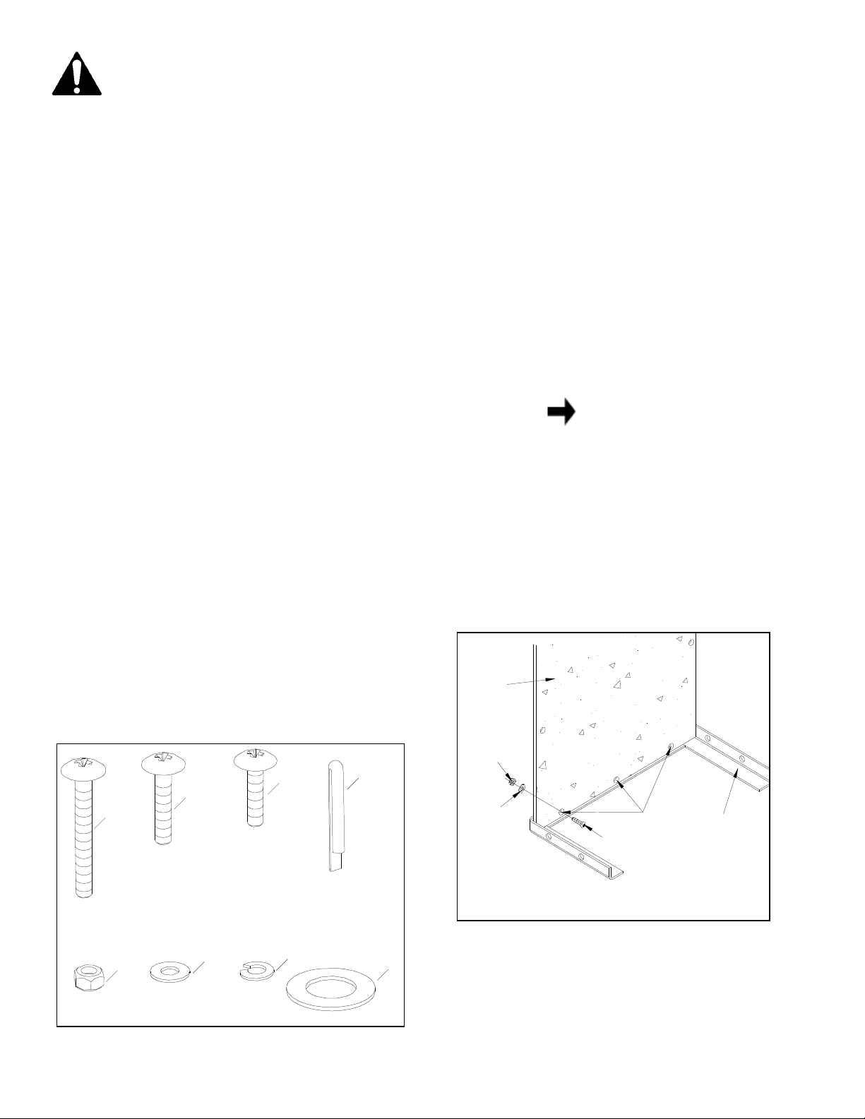
This cart is designed for carrying materials only, and When assembling your cart, place the heads of all
NEVER to carry passengers. screws to the inside and hex nuts with flat washers
2. Be cautious of any steep grade or hills; stay clear of to the outside.
steep grades.
3. Use caution when loading cart to avoid tipping. 1. Lay the front angle assembly down (flat) on floor
4. Avoid large holes and ditches when transporting and stand the bottom panel in position as shown in
loads. figure 2.
5. CAPACITY OF THIS CART IS 300LBS.
DO NOT OVERLOAD CART!
Your Garden Cart carton contains a hardware
package with parts as shown in the chart below
and in figure 1.
Contents of Hardware Pack: (See figure 1)
REF. QTY. DESCRIPTION
A 8 Screws,M6X50 front angle assembly. Start three M6X25 screws
B 4 Screws,M6X30 through bottom panel, then through angle. Secure
C 15 Screws,M6X25 screws with Ф6 flat washers and M6 hex nuts.
D 4 Cotter Pins
E 27 Hex Nuts,M6
F 23 Flat Washer,Ф6
G 4 Lock Washer,Ф6
H 4 Large Flat Washer
NOTE
The bottom panel has one galvanized
edge; this is the rear. The front edge
has three holes. See figure 2.
2. Line up three holes in bottom panel with holes in
Tighten securely.
BOTTOM
PANEL
See figure 2.
HARDWARE REFERENCE CHART
FIGURE 1
M6X50
M6
HEX
NUT
C
B
A
M6X25
M6X30
E
F
G
D
Ф
6
FLAT
WASHER
H
M6
SCREW
THREE
HOLES
FRONT
EDGE
FRONT
ANGLE
FIGURE 2
1

3. Turn the front angle assembly and bottom panel 7. Stand the cart on its front end with the front angle
6. Secure both side angle assemblies to the bottom
upside down as shown in figure 3. assembly on the floor. See figure 5.
4. Lay the two side angles on the bottom panel so 8. Temporarily place four large flat washers
that the two holes for the axle clamps are closer to (used on wheel axle) on the inside of front angle
the front angle assembly. See figure 3. assembly. See figure 5.
5. Secure both axle clamps to the side angles and NOTE
the bottom panel using four M6X30 screws, These washers act as shims and are
lock washers and hex nuts.
tighten until axle is assembled
M6
SIDE
ANGLE
AXLE
CLAMP
M6X30
SCREW
HEX
NUT
Ф
6
LOCK
WASHER
Only finger
. See figure 3. remove them later to use on axle.
FRONT
ANGLE
ASS'Y
just for assembly purposes. You will
BOTTOM
PANEL
LARGE
FLAT
WASHER
BOTTOM
PANEL
SIDE
ANGLE
FRONT
ANGLE
ASS'Y
FIGURE 3 FIGURE 5
9. Lay the front panel down onto the front angle
assembly, on top of the four large washers. See
panel using four M6X25 screws, flat washers and figure 6.
hex nuts.
are in place
M6X25
SCREW
Only finger tighten until all four screws
, then tighten securely. See figure 4.
Ф
6
FLAT
WASHER
M6
HEX
NUT
FRONT
PANEL
FRONT
PANEL
FRONT
ANGLE
ASS'Y
LARGE
FLAT
WASHER
FIGURE 4 FIGURE 6
2
 Loading...