

Page 1

MANUFACTURING QUALITY LAWN CARE EQUIPMENT SINCE 1945
Owner’s
Manual
FC-17
17 Cubic Foot
Dump Cart
IMPORTANT
Read and follow all
Safety Precautions
and Instructions
Before Operating this
Equipment.
1602 CORPORATE DRIVE PO BOX 67 WARRENSBURG, MISSOURI 64093
11766 REV. 05-340
Made In CHINA
PH 660. 747. 8183 FAX 660. 747. 8650
swisherinc.com
Page 2

LIMITED WARRANTY
The manufacturer’s warranty to the original consumer purchaser is: This product is free
from defects in materials and workmanship for a period of One (1) year from the date of
purchase by the original consumer purchaser. We will repair or replace, at our discretion,
parts found to be defective due to materials or workmanship. This warranty is subject to the
following limitations and exclusions:
1) Commercial Use This product is not intended for commercial use and
carries no commercial warranty.
2) Limitation This warranty applies only to products which have been
properly assembled, adjusted, and operated in accordance
with the instructions contained within this manual. This
warranty does not apply to any product of Swisher Mower
Co., Inc., that has been subject to alteration, misuse, abuse,
improper assembly or installation, shipping damage, or to
normal wear of the product.
3) Exclusions Excluded from this warranty are normal wear, normal
adjustments, and normal maintenance.
In the event you have a claim under this warranty, you must return the product to an
authorized service dealer. All transportation charges, damage, or loss incurred during
transportation of parts submitted for replacement or repair under this warranty shall be borne
by the purchaser. Should you have any questions concerning this warranty, please contact
us toll-free at 1-800-222-8183. The model number, serial number, date of purchase, and the
name of the authorized Swisher dealer from whom you purchased the mower will be needed
before any warranty claim can be processed.
THIS WARRANTY DOES NOT APPLY TO ANY INCIDENTAL OR CONSEQUENTIAL
DAMAGES AND ANY IMPLIED WARRANTIES ARE LIMITED TO THE SAME TIME
PERIODS STATED HEREIN FOR ALL EXPRESSED WARRANTIES. Some states do not
allow the limitation of consequential damages or limitations on how long an implied warranty
may last, so the above limitations or exclusions may not apply to you. This warranty gives
you specific legal rights and you may have other rights, which vary from state-to-state. This is
a limited warranty as defined by the Magnuson-Moss Act of 1975.
2
2
Page 3
Pre
-
assembly Instructions:
For best results, follow all directions step by step.
Part
Open box before beginning to assemble.
HELPFUL TIP: Read all instructions before starting to assemble.
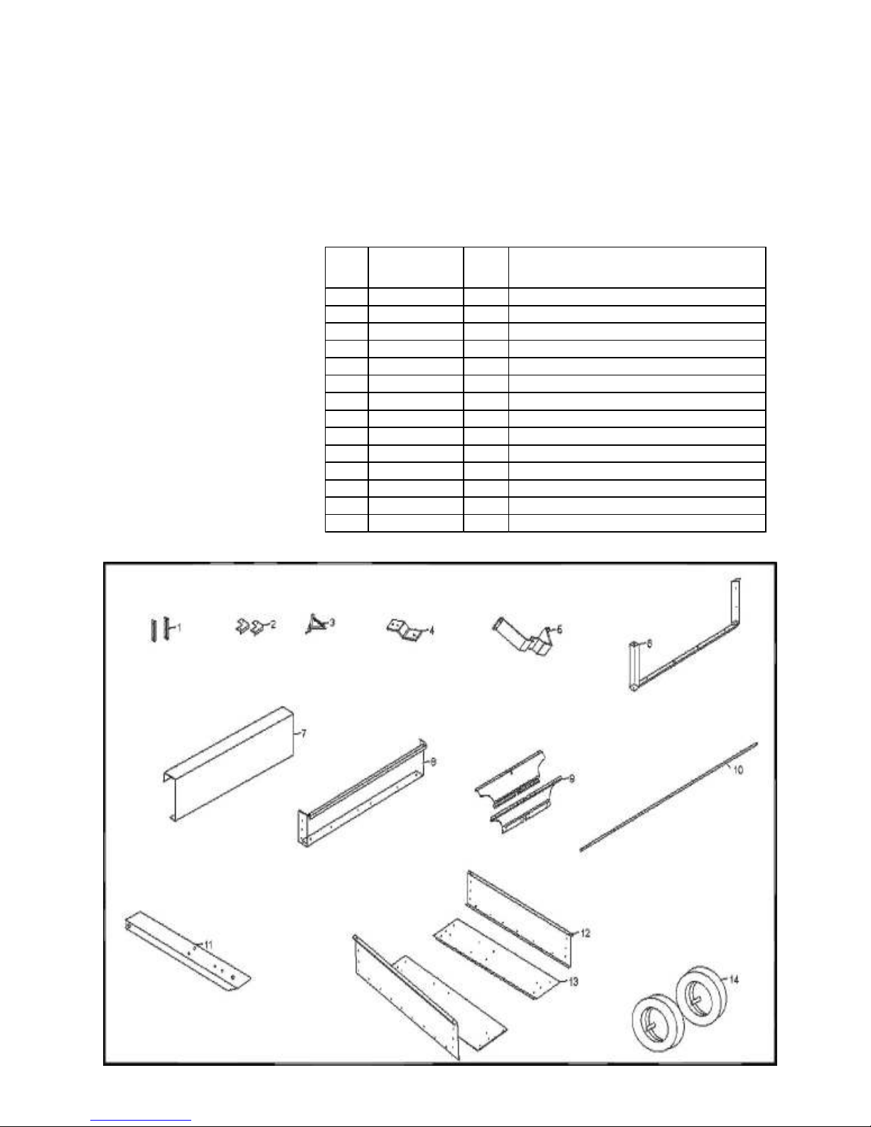
Check Parts and Hardware:
Group together and check that all hardware and parts are included.
Refer to parts and hardware illustrations below.
If you are missing parts, contact the place of purchase for missing hardware or parts.
Tools Required:
2 – 10mm wrench
1 – 14mm wrench
1 – Screwdriver
1 – Medium Pliers
PARTS LISTING:
Ref.
No.
1 12191 2 Tail Gate Holding Guide
2 12192 2 Corner Cop
3 12193 1 Release Latch (4 pieces)
4 12194 1 Hitch Bracket
5 12195 1 Stand Bracket
6 12196 1 Tailgate Brace (3 pieces)
7 12197 1 Main Tailgate
8 12198 1 Front Panel
9 12199 1 Wheel Support
10 12200 1 Wheel Axle
11 12201 1 Cart Tongue
12 12202 2 Main Panel Side Body
13 12203 2 Main Panel Bottom Body
14 12204 2 Wheel Assembly
No. Qty Part Description
Page 4
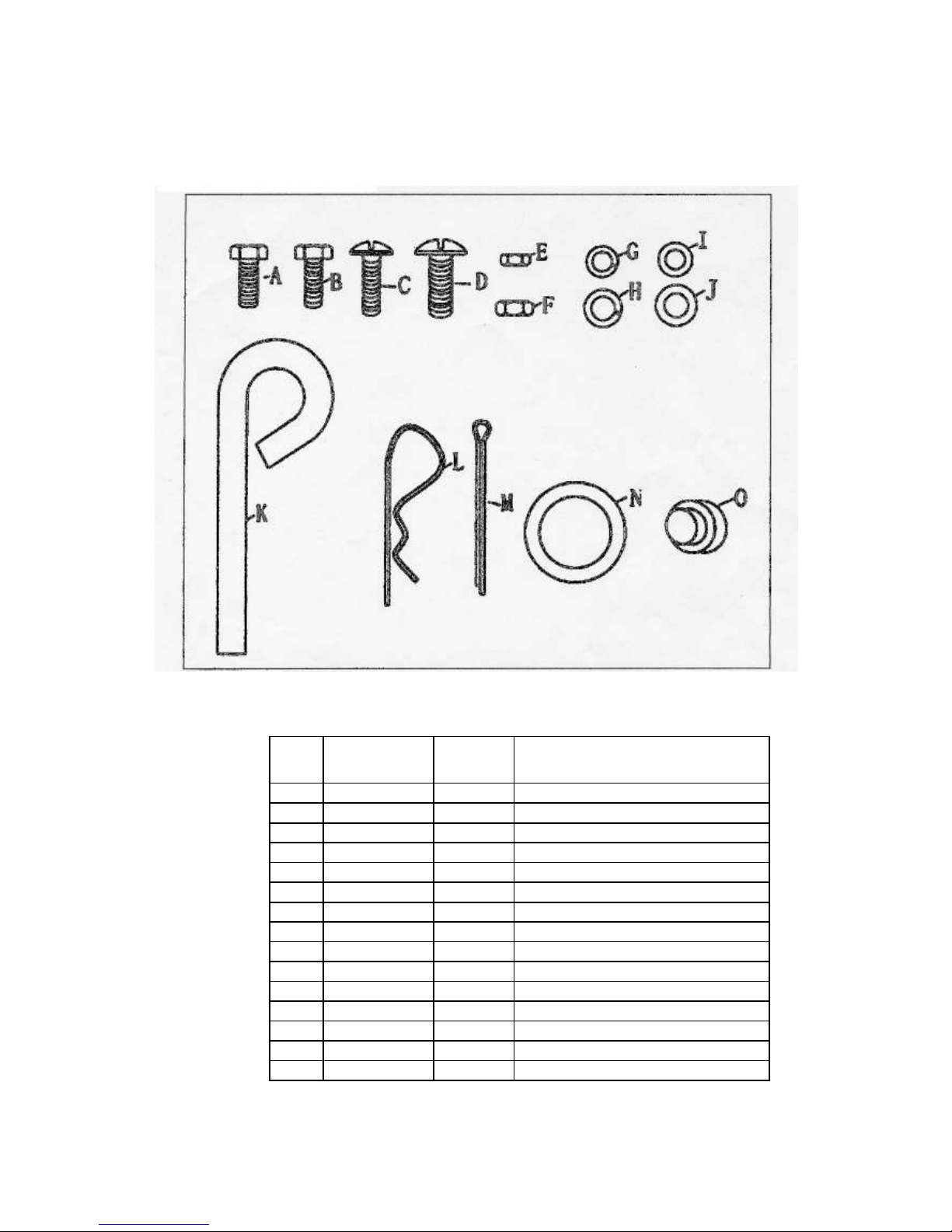
HARDWARE PHOTOS ARE NOT ACTUAL SIZE
Part
HARDWARE LISTING:
Ref
Let.
A NB719 10 M8 x 20 Hex Bolt
B 10619 2 M6 x 20 Hex Bolt
C 12205 49 M6 X 16 Round Head Bolt
D 12186 22 M8 X 16 Round Head Bolt
E NB600 51 M6 Nut
F NB718 32 M8 Nut
G NB135 51 Ø 6 Lock Washer
H NB159 32 Ø 8 Lock Washer
I NB274 51 Ø 6 Flat Washer
J NB275 32 Ø 8 Flat Washer
K 12206 1 Lock Pin
L NB247 1 Hair Pin
M NB603 2 Cotter Pin
N NB179 4 Large Washer
O 12207 2 Wheel Hub Cap
No.
Qty. Part Description
Note: You may have extra nuts & Bolts when finished
Page 5

Assembly Instructions:
Step 1: Main Panels Assembly
Attach the main panels bottom body and side body
by M8 Bolts, Φ8 Lock Washer and M8 Nut, tighten
the bolts.
Step 1 Hardware Needed:
18-M8x20 Round Head Bolt
18-Φ8 Lock Washer
18-M8 Nut
Figure #1
Step 2: Attach Main Cart Panels
Set cart upright as shown in figure #1 on a level
surface. Connect the center of the panels using
M6x16 bolts, Φ6 lock washer, and M6 nut.
Do not tighten bolts.
Step 2 Hardware Needed:
9 – M6x16 Bolt
9 –Φ6 Lock Washer
9 – M6 Nut
Figure #2
Page 6

Step 3: Attach Tailgate Brace and Tailgate Holding Guides
First attach the bottom piece of the tailgate brace using M8x20 round slotted bolts, Φ8 lock washer, and M8
just assembled. Next, attach the front panel using M6x16 bolts,
Tighten bottom bolts, side bolts, and the
Nut. Do not tighten. Next, attach the side pieces of the tailgate brace to the outside, and attach the tailgate
holder guide to the inside of panel. Use M6x20 bolts, Φ6 lock washer, and M6 nut. Same bolt for both pieces
SEE Figure #2.
Do not tighten bolts.
Step 3 Hardware Needed:
6 – M8x20 Round Head Bolt
6 –Φ8 Lock Washer
6 – M8 Nut
6 – M6x20 Bolt
6 –Φ6 Lock Washer
6 – M6 Nut
Figure #3
Step 3A:
Now tighten bottom bolts, and side bolts. Wait to tighten bolts connecting the bottom of main body panels
until the next step.
Step 4: Attach Front Panel
With care, completely turn over the main body to rest the end which was
Φ6 lock
washers, and M6 nuts. NOTE THE HOLES LEFT EMPTY. See Figure #3.
center connection bolts from Step 1.
Step 4 Hardware Needed:
10 –Φ6 Lock Washer
10 – M6 Nut
10 – M6x16 Bolt
Figure #4
Page 7

Step 5: Attach Wheel Support
Attach the wheel support as shown in figure #4 below using
M8x20 round head bolts, Φ8 lock washer, and M8 nut. Fully
tighten bolts.
Step 5 Hardware Needed:
8 – M8x20 Round Head Bolt
8 –Φ8 Lock Washer
8 – M8 Nut
Figure #5
Step 6: Attach Stand Bracket Support
Attach the stand bracket as shown in figure #5
using M6x16 bolts, Φ6 lock washer, and M6 nut.
Fully tighten bolts.
Step 6 Hardware Needed:
4 – M6x16 Bolt
4 –Φ6 Lock Washer
4 – M6 Nut
Figure #6
Page 8

Step 7: Attach Front Corner Cap/Brace
Attach front corner braces and bolt back bracket
as shown in figure #6 using M6x16 bolts,
Φ6 lock washer, and M6 nut.
Fully tighten bolts.
Step 7 Hardware Needed:
6 – M6x16 Bolt
6 –Φ6 Lock Washer
6 – M6 Nut
Figure #7
Step 8: Attach Latch Lock to Tongue
Attach latch lock to tongue using M6x16 bolts, Φ6 lock washer, and M6 nut.
See figure #7 for direction of latch lock. Note: do not connect latch lock pieces to each other, only
to the tongue.
Fully tighten bolts.
Step 8 Hardware Needed:
2 – M6x16 Bolt
6 –Φ6 Lock Washer
6 – M6 Nut
Note: Latch Lock includes:
1 – Spring
2 – Side pieces
1 – Angle Lock
Figure #8
Page 9

Step 9: Attach Hitch Pin Bracket to Tongue
Trailer Tongue
Tighten after the assembly is complete
Attach hitch pin bracket to tongue using
8x20 bolts, Φ8 lock washer, and M8 nut.
See figure #8. Fully tighten bolts.
Step 9 Hardware Needed:
2 – M8x20Bolt
2 –Φ8 Lock Washer
2 – M8 Nut
Figure #9
Step 9A: Attach Axle and
See Figure 9A. Slide the axle into the wheel
support one half of the way, till the end
starts through the center. Align the hole in
the tongue with the end of the axle. Slip
axle through the tongue and all the way
through the support. Note: The bolts in the
axle support may need to be loosened,
Step 10: Attach Wheel
Assembly
See figure 10. Note: Axle will fit tightly with
wheel, turn wheel while sliding onto axle. First, slide
flat washer onto axle, then wheel, then flat washer.
Secure using cotter pin, spread end of cotter pin to
keep in place. Hub cap fits onto washer.
Repeat for other wheel.
Step 10 Hardware Needed:
4 – Flat Washer
2 – Cotter Pin
2 – Hub Caps
Figure #10
Page 10

Final Step: Insert Tailgate and Adjust Side Panels
Turn Cart upright onto wheels. Insert the tailgate into the tai
The Cart is fully assembled. Be sure all connections are tight.
lgate guides. Move back end of side panels by
hand in/out so the tailgate slides in and out of guides easily.
Insert bolts into the lower back corners of tailgate brace with tailgate in place.
Fully tighten.
Hardware needed:
4 – M6x20 Bolt
4 – M6 Lock Washer
4 – M6 Nut
OPERATION NOTES:
A full capacity load is 1500 pounds, DO NOT exceed rated capacity.
Cart only to be used with lawn tractor or ATV.
Cart is not to for highway use. Do not exceed 5mph when towing.
Check that tires are inflated properly. Pressure should be approx. 14psi.
Grease axle and wheel bearing area regularly or when needed.
Page 11

Notes
Page 12

MANUFACTURING QUALITY LAWN CARE EQUIPMENT SINCE 1945
Owner’s
Manual
FC-17
IMPORTANT
Read and follow all
Safety Precautions
and Instructions
Before Operating this
Equipment.
ATV & LAWN ACCESSORIES
WHEN ORDERING PARTS, PLEASE HAVE THE
FOLLOWING INORMATION AVAILABLE:
* PRODUCT – ________________
* SERIAL NUMBER - _______________
* MODEL NUMBER - _______________
TYPE - _______________
* PART NUMBER WITH PAINT CODE
* PART DESCRIPTION
TELEPHONE - 1-800-222-8183
FAX - 1-660-747-8650
SWISHER MOWER & MACHINE CO. INC.
SWISHER MOWER & MACHINE CO. INC.
SWISHER MOWER & MACHINE CO. INC.SWISHER MOWER & MACHINE CO. INC.
1602 CORPORATE DRIVE
P.O. BOX 67
WARRENSBURG, MO 64093
swisherinc.com
 Loading...