

Page 1
Visit us at www.swisherinc.com
OWNER’S
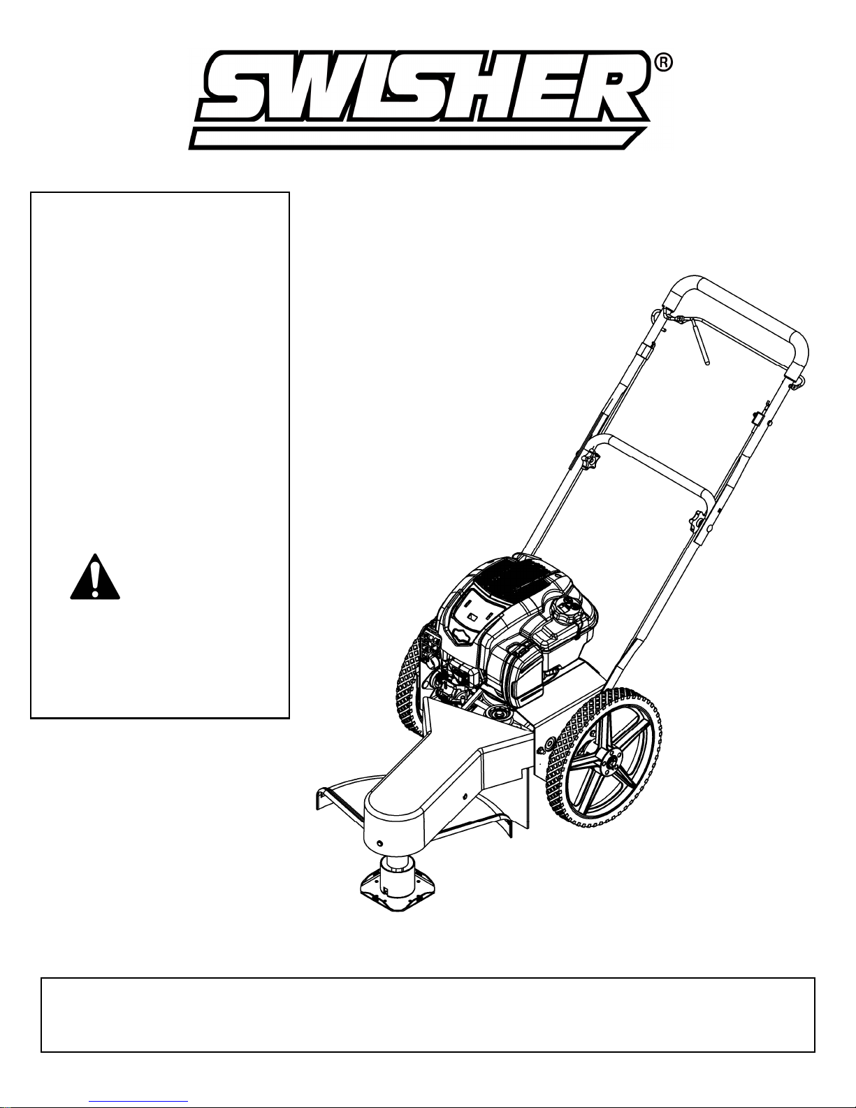
Self-Propelled
MANUAL
MODEL NO.
STARTING SERIAL # L215-335001
STP67522BS
IMPORTANT
Read and follow all
Safety Precautions
and Instructions
before operating this
equipment.
Easy Glide
Assembly
Operation
Service and
Adjustment
Repair Parts
1602 CORPORATE DRIVE, WARRENSBURG MISSOURI 64093
19129 REV 15-335
Made In The
USA
of US and Global Parts
SWISHER ACQUISITION INC.
PHONE 660-747-8183 FAX 660-747-8650
Page 2

LIMITED WARRANTY
The manufacturer’s warranty to the original consumer purchaser is: This product is free from defects in
materials and workmanship for a period of two (2) years from the date of purchase by the original consumer
purchaser. We will repair or replace, at our discretion, parts found to be defective due to materials or
workmanship. This warranty is subject to the following limitations and exclusions:
1) Engine Warranty All engines utilized on our products have a separate warranty extended
to them by the individual engine manufacturer. Any engine service
difficulty is the responsibility of the engine manufacturer and in no way
is Swisher or its agents responsible for the engine warranty. The Briggs
& Stratton Engine Service Hot Line is 1-800-233-3723.
2) Commercial Use This product is not intended for commercial use and carries no
commercial warranty.
3) Limitation This warranty applies only to products which have been properly
assembled, adjusted, and operated in accordance with the instructions
contained within this manual. This warranty does not apply to any
product of Swisher that has been subject to alteration, misuse, abuse,
improper assembly or installation, shipping damage, or to normal wear
of the product.
4) Exclusions Excluded from this warranty are normal wear, normal adjustments, and
normal maintenance.
In the event you have a claim under this warranty, you must return the product to an authorized
service dealer. All transportation charges, damage, or loss incurred during transportation of parts
submitted for replacement or repair under this warranty shall be borne by the purchaser. Should
you have any questions concerning this warranty, please contact us toll-free at 1-800-222-8183.
The model number, serial number, date of purchase, and the name of the authorized Swisher dealer
from whom you purchased the trimmer will be needed before any warranty claim can be processed.
THIS WARRANTY DOES NOT APPLY TO ANY INCIDENTAL OR CONSEQUENTIAL
DAMAGES AND ANY IMPLIED WARRANTIES ARE LIMITED TO THE SAME TIME
PERIODS STATED HEREIN FOR ALL EXPRESSED WARRANTIES. Some states do not allow
the limitation of consequential damages or limitations on how long an implied warranty may last,
so the above limitations or exclusions may not apply to you. This warranty gives you specific legal
rights and you may have other rights, which vary from state-to-state. This is a limited warranty as
defined by the Magnuson-Moss Act of 1975.
2
Page 3

tructions, to operate
Safety Instructions
This Safety Alert Symbol indicates important messages in this
manual. When you see this symbol, carefully read the message that
follows and be alert to the possibility of personal injury.
• Read, understand and follow all instructions in the manual and on the trimmer
before starting.
• Read this manual carefully. Become familiar with the controls and how to
operate the unit properly.
• Only allow responsible adults, who are familiar with the ins
the unit.
• Clear the area of objects such as rocks, toys, etc. that could be thrown by the
unit.
• Be sure the area is clear of other people before trimming. Stop the unit if
anyone enters the area.
• Be aware of the direction of the trimmer discharge and do not direct it at
anyone. Do not direct trimmer discharge at breakable objects, such as
windows, etc.
• Do not operate trimmer without all guards and shields in place.
• Never leave the machine running unattended.
• Trim only in daylight or good artificial light.
• Do not operate the trimmer while under the influence of alcohol or drugs.
• Watch for traffic when operating near roadways.
• Use the trimmer as the manufacturer intended and as described in the
manual.
• Do not operate trimmer if it has been dropped or damaged in any manner.
Always have the damage repaired before operating.
• Always wear safety glasses or eye shields when using the trimmer.
• Dress properly. Do not operate the trimmer when barefoot or wearing open
sandals. Wear only solid shoes for good traction when trimming. Wear a long
sleeved shirt or jacket and long pants. Do not trim in shorts.
• Keep your eyes and mind on your trimmer and the area being trimmed. Do
not let other interests distract you.
• Do not put hands and feet near or under rotating parts.
• Before cleaning, inspecting or repairing your trimmer, stop the engine and
disconnect the spark plug wire and keep it away from the spark plug to
prevent accidental starting.
• Do not operate the trimmer if it vibrates abnormally. Excessive vibration is a
sign of damage. Stop the engine and safely check for damage and repair as
required.
• Do not operate the trimmer in wet grass, where good footing may not be
possible. Walk, never run.
• Stop the trimmer when crossing gravel drives, etc.
3
Page 4

Slopes are a major factor related to loss of control and slip accidents,
Slope Operation
•
•
Use extra care when approaching blind corners, shrubs, trees or other objects
which can result in severe injury. All slopes require extra caution. If you
feel uneasy on it do not trim it.
DO: Trim across the face of a slope and not up and down.
• DO: Remove objects such as rocks, tree limbs, etc.
• DO: Watch for holes, ruts or bumps. Tall grass can hide obstacles.
• DO NOT: Mow near drop-offs, ditches or embankments. The operator could
lose footing or balance.
• DO NOT: Trim excessively steep slopes.
• DO NOT: Trim on wet grass. Reduced footing could cause slipping.
Keep children out of the area and under the watchful care of another
responsible adult.
Be alert and turn the machine off if children enter the area.
•
Before and when backing, look behind and down for small children.
•
Never allow children to operate this machine.
•
•
that may obstruct vision.
Children
• Use extra care handling gasoline and other fuels. They are flammable and
vapors are explosive.
• Use only an approved container for fuel.
• Never remove gas cap or add fuel with the engine running.
• Allow engine to cool before refueling. Do not smoke while refueling.
• Never refuel the machine indoors.
• Never store the machine or fuel container where there is an open flame, such
as a water heater.
• Never run a machine inside a closed area.
• Keep nuts and bolts tight and equipment in good condition.
• Never tamper with safety devices.
• Keep machine free of grass, leaves or other debris build up. Clean oil or fuel
spillage. Allow machine to cool before storing.
• Stop and inspect the equipment if you strike an object. Repair if necessary
before restarting.
• Never make repairs or adjustments with the engine running.
Service
4
Page 5
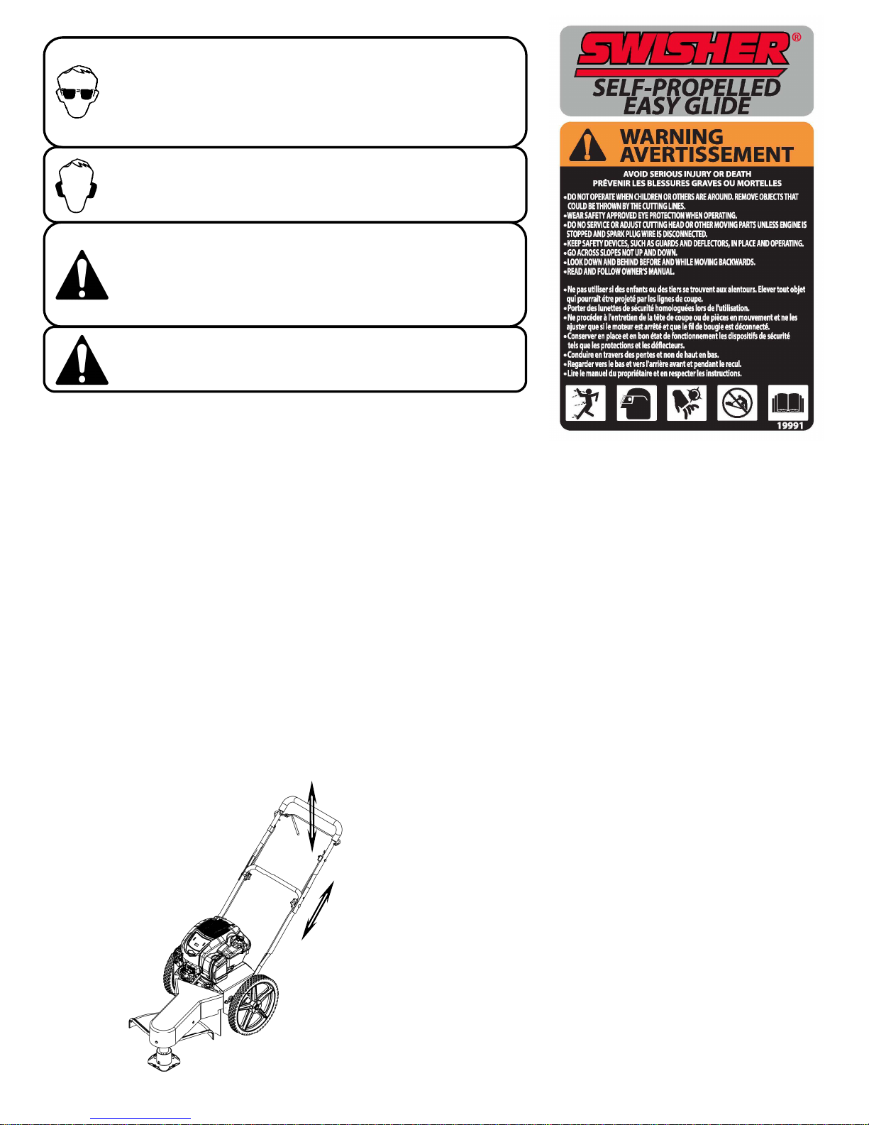
The operation of any mower can encounter foreign
hardware removed in previous step. Snug, but
objects to be thrown into the eyes, resulting in severe eye
damage. Always wear certified safety glasses or widevision safety goggles over spectacles before starting any
cutting machine and while operating such a machine.
The operation of any mower produces sound waves that
are damaging to the human ear. Ear protection is
recommended.
CAUTION!
Tragic accidents can occur if the operator is not alert to the
presence of children. Children are often attracted to the
machine and the mowing activity. Never assume that
children will remain where you last saw them.
Do not operate the trimmer if it vibrates abnormally. Excessive
vibration is a sign of damage. Stop the engine and safely
check for damage and repair as required.
Warning Decal
19991
Contents of Box:
• Trimmer
Parts bag containing:
• Manual
• Engine manual
• Safety goggles
• Bottle of engine oil
• Trimmer line
• Hex wrench
Assembly
Tools Required:
• ½” Wrench
Installation of handles:
1. Remove loose fasteners from trimmer frame
handle holes.
2. Pivot lower handle up and align holes in
handle with holes on trimmer frame. Install
do not tighten bolts.
3. Attach upper handle to lower handle using
knobs and fasteners provided with lower
handle.
4. Adjust handles for comfortable operation.
5. Tighten all bolts.
Handles may be adjusted up and down and in and out
for comfortable operation.
Handle Adjustment
5
Page 6
Preparing Unit For First Use
• Fill engine crankcase with oil. A 20oz. bottle has been provided with this unit. A new unit
requires 18-20oz. DO NOT OVERFILL.
• Fill the engine fuel tank with gasoline. GASOLINE SHOULD BE ADDED OUTSIDE IN A
WELL-VENTILATED AREA.
• Check to ensure string has been installed properly. A diagram is provided just above the trimmer
head for proper installation.
• Refer to engine manufacture’s manual for oil and fuel specifications.
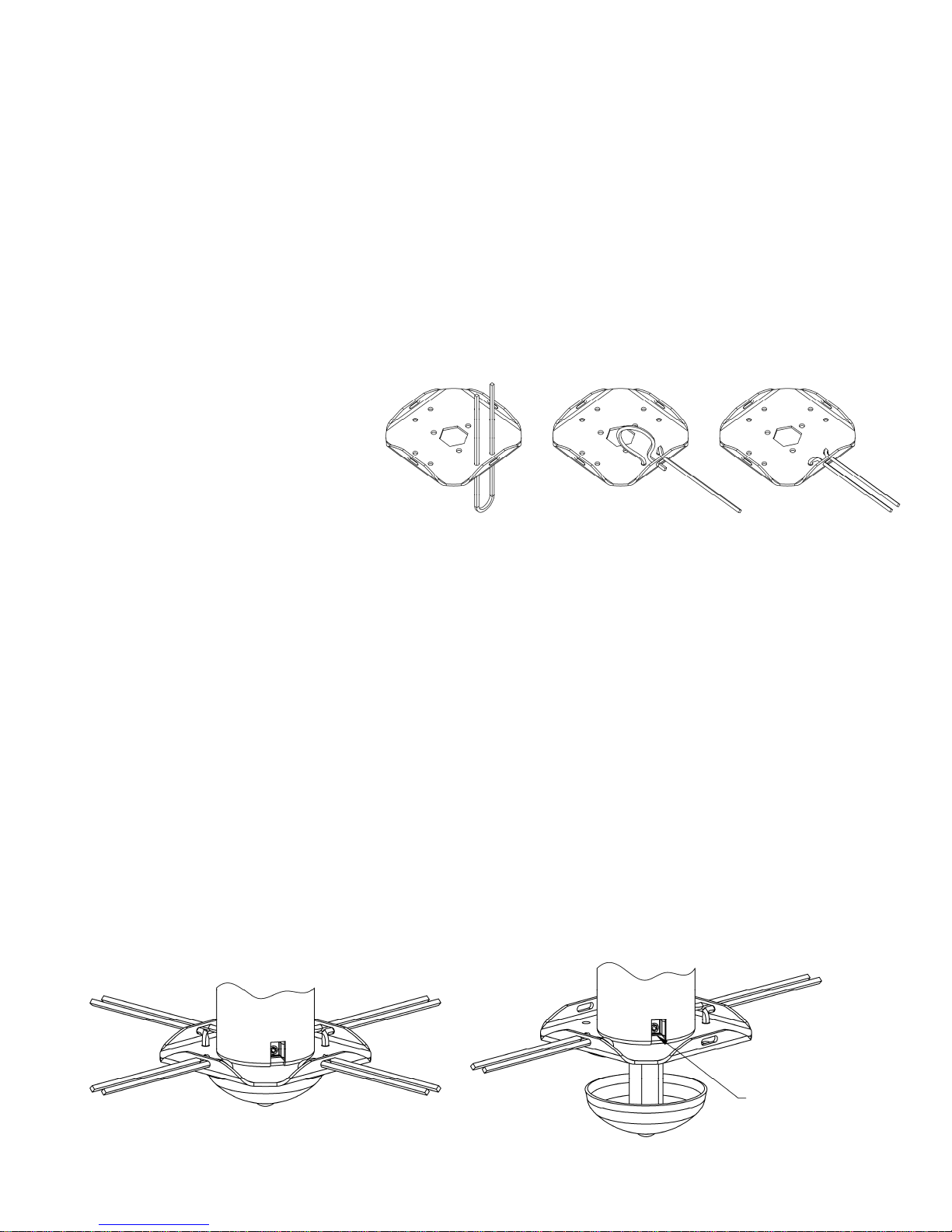
Installing Trimmer Line
Important! Use the proper length of line. Using a line too long for the unit will cause
stalling and unacceptable operation.
Use 18” Trimmer Line
Part Number P3618
• Loosely fold trimmer line in half.
• Insert line through the bottom holes of the cutting disc (Step 1).
• Bring ends around and through the slot in the cutting disc flange (Step 2).
• Pull ends to tighten loop (Step 3).
Step 1
Step 3Step 2
Trimmer Line Positions
Trimmer line attachment positions:
• Trimmer is equipped with 4 trimmer line attachment points.
• When mowing with trimmer, the 4 trimmer line configuration is recommended for a more consistent,
even cut.
• When trimming tall or thick vegetation, the 2 trimmer line configuration is recommended for improved
To adjust cutting height:
1. Loosen set screw using hex wrench provided.
2. Slide cutting head up or down to desired cutting height.
3. Tighten set screw.
4. Any cutting height may be used with either trimmer line configuration.
performance.
Set Screw
4 Trimmer line Configuration
Shown set at Low cutting height
2 Trimmer line Configuration
Shown set at High cutting height
6
Page 7

Operation
•
Important! To ensure proper operation, clean the engine and trimmer regularly. Remove any build up
of chaff from the top of the engine. During operation debris may get wrapped around trimmer head.
Prolonged use in this condition may result in excessive wear and part failures. Periodically turn off trimmer
and remove debris.
To start the trimmer:
1. Remove any built up debris from engine and trimmer head.
2. Move throttle control to “FAST”.
3. Firmly grasp rope handle and pull out slowly until resistance is felt. Then pull back rapidly with a
full arm stroke.
4. When engine starts, leave throttle control at “FAST”. Throttle control must be set in the fast
position for maximum performance.
5. Engage trimming head.
6. Begin trimming.
To engage/disengage trimmer head:
• Engage: Bring control bail into contact with the upper handle and grip it together with the handle.
If trimmer head does not fully engage, see belt adjustment section.
• Disengage: Release control bail. Trimmer head should stop within a few seconds. If it does not,
To engage/disengage transmission:
• Engage: Bring transmission engagement lever into contact with the upper handle and grip it
• Disengage: Release transmission engagement lever.
To stop the trimmer:
1. Release the control bail.
2. Move throttle control lever on engine to “SLOW” for a few seconds then move to “STOP”.
see belt adjustment section.
together with the handle.
Important!
For safest operation, make sure debris is directed away from you and others.
Troubleshooting
• If engine will not start, remove and check air filter to make sure filter and
carburetor are clean.
Trimming Tips
Do not lift the trimmer head when trimming. Let the head rest lightly touching the ground.
• Keep an eye on the length of the trimmer line. As the line gets shorter they become less effective at
cutting and will take longer to trim properly. Replace the line as necessary (see Installing Trimmer Line).
• Do not trim wet grass.
• Use caution when trimming slopes.
• Use the proper length of line. Using a line too long for the unit will cause stalling and
7
Page 8
Trimmer Maintenance
WARNING
–
ALWAYS STOP ENGINE AND DISCONNECT SPARK PLUG
e belts may need to be adjusted using the following instructions. Indications that the belts
.
Make sure your trimmer is in safe working condition by keeping the following guidelines in mind every time you
use your trimmer.
• Keep trimmer in good operating condition and keep all guards and shields in place. DO NOT operate this
trimmer if any of the shields and guards are missing.
• Check all fasteners for secure fit to keep equipment in safe working order. Make adjustments as necessary.
• To reduce fire hazards, keep engine free of grass, leaves or excessive grease.
• DO NOT operate trimmer with a damaged or missing muffler. DO NOT tamper with exhaust system; this may
cause a fire hazard.
• DO NOT operate engine if air cleaner or the cover over the carburetor air intake is missing. Removal of these
parts could create a fire hazard.
• Before cleaning, making adjustments or repairing the trimmer, STOP engine, disconnect spark plug wire and
allow engine to cool.
• Handle gasoline with care. DO NOT smoke or use open flame near gasoline. Use only approved gasoline
containers. Never fuel or run trimmer in poorly ventilated areas, such as a garage or utility building.
• Always replace fuel tank cap. Be sure to clean up any spilled gasoline.
• Do not change the engine governor settings or over-speed the engine; severe injury or damage may result.
• Never store mower with gasoline in the tank inside a building where fumes may reach an open flame or spark.
Always allow engine to cool before storing.
NEVER ADD GASOLINE TO A HOT ENGINE – ALLOW ENGINE TO
COOL BEFORE ADDING GASOLINE.
WIRE BEFORE PERFORMING ANY ADJUSTMENTS OR SERVICE.
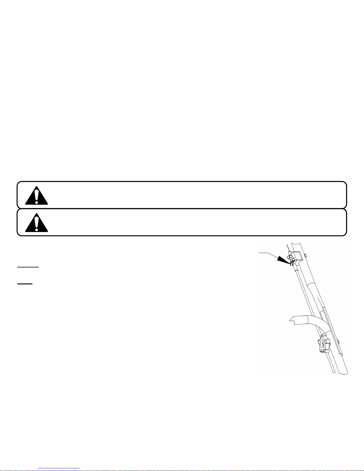
Thumb wheel
Engine
• Refer to the engine service manual provided with this unit.
Belts
• Occasionally check the belts for wear. A worn belt should be replaced.
Belt Adjustment
During the first few hours of operation all belts go through a “break-in period” after which
th
need to be adjusted include:
• Loss of power at the trimming head causing the head to spin unusually slow or stop.
• Excessive wear on belt due to slipping.
• The belt that powers the transmission is designed to be under constant tension and
needs no further adjustment.
• The belts used to engage/disengage the trimmer head can be adjusted using the
following instructions:
1. Locate the thumb wheel adjuster on the control cable (see illustration).
2. Release control bail to disengage trimmer head.
3. Rotate thumb wheel a few turns counterclockwise
4. Re-engage trimmer head.
5. If trimmer head has not returned to normal operation, repeat steps 2-4.
(from normal operating position).
Important!
Excessive force should NOT be required to fully engage control bail.
Do not over tighten cable adjuster. This may cause the cable to break
8
Page 9
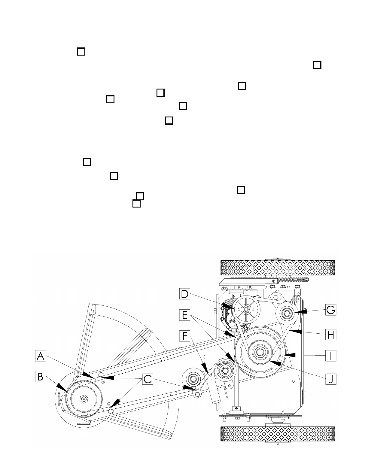
Belt Replacement
Head Engagement Belt A Replacement
1. Remove front belt cover.
2. Loosen or remove fasteners used to attach engine to allow engine to shift. Slide or tilt engine so lower engine pulley I moves
away from transmission, creating a gap to allow belt to be removed.
3. Remove old belt.
4. Install new belt by first routing belt under the engine and around lower engine pulley I .
5. Then route belt between two idler pulleys as shown F .
6. Install belt around front pulley B .
7. Ensure that belt is correctly installed between the belt guides C and adjacent pulley.
8. Ensure that belt is correctly installed in the grove of each pulley.
9. Ensure that belt is over the top of the transmission axle E .
10. Tighten or reinstall fasteners used to attach engine.
11. If belt tension had previously been adjusted, reset thumb wheel adjuster by rotating wheel clockwise as far as adjuster will allow
(see illustration in belt adjustment instructions). If head does not properly engage refer to belt adjustment instructions.
12. Reinstall front belt cover.
Transmission Power Belt H Replacement
1. Remove front belt cover.
2. Remove Head Engagement Belt A per instructions above.
3. Remove old belt.
4. Install new belt by first routing belt under the engine and around upper engine pulley J .
5. Then route belt around transmission pulley D .
6. Finally route belt around rear idler pulley G . The idler pulley is spring loaded, making it difficult to finish belt installation. To
ease belt installation push idler pulley toward transmission pulley while wrapping belt around idler pulley. CAUTION – Pinch
Hazard: Ensure that you do not get any part of your body between the belt and the pulleys as this may cause injury.
7. Reinstall Head Engagement Belt per instructions above.
8. Reinstall front belt cover.
9
Page 10
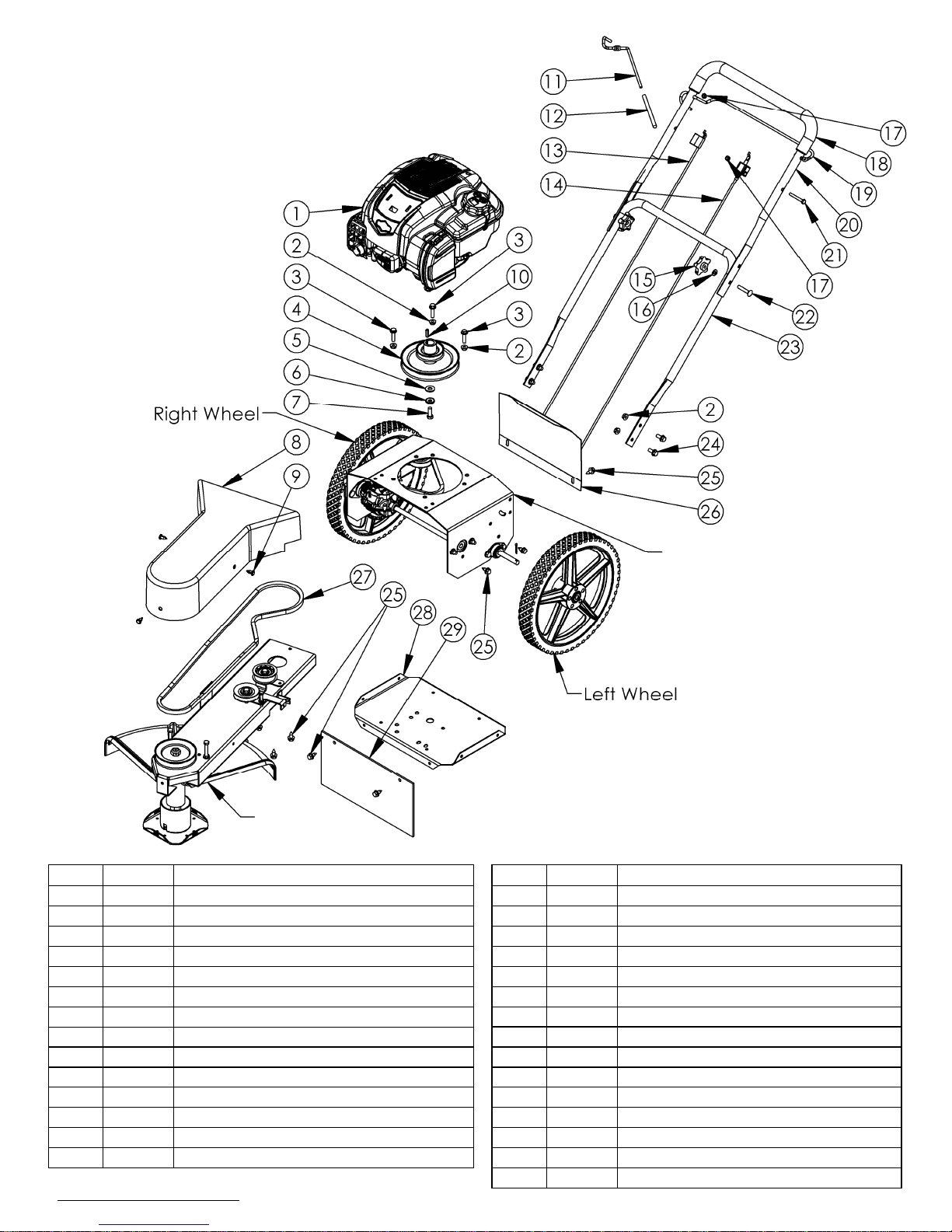
Assembly
See Detail
Page 11
Item # Part # Description Item # Part # Description
1 N/A Engine - Briggs & Stratton 15 2030 Knob - Black Plastic
2 NB170 Nut - Serrated Flange 5/16-18 16 NB275 Washer - SAE Flat 5/16
3 NB253 Bolt - Serrated Flange, 5/16-18 X 1 1/4 17 NB180 Nut - Nyloc 1/4-20
4 19018 Pulley - Double Drive, Trimmer 18 19561 Grip - Handle, Anti-Vibration
5 NB271 Washer - USS Flat 3/8, ZY Carbn Stl 19 19005 Bail - Trimmer
6 NB607 Washer - SP Bellville 20 19017* Handle - Top, SP Trimmer
7 NB238N Bolt - HHC 3/8-24 X 1 21 NB218 Bolt - 1/4-20 X 2 HCC GR5 ZY
8 2019 Guard - Belt 22 NB587 Bolt - Carriage, 5/16-18 X 1 3/4
9 19135 Clip - Panel 23 10399* Handle - Lower
10 9030 Key Stock - 3/16 X 1 24 NB596 Bolt - Serrated Flange, 5/16-18 X 3/4
11 19027 Lever - Transmission Engagement 25 26X249 Screw - .312-18 X .75
12 19823 Grip - STP Lever 26 19016* Cover - Rear, SP Trimmer
13 19101 Cable - Transmission Control; STP 27 19034 Belt - 60", Trimmer
14 19006 Cable - Control, Trimmer 28 2006* Base - Lower Motor
When ordering replacement parts
* USE PAINT CODE: TK=BLACK
See Detail
Page 12
29 19004 Shield - Rubber
10
Page 11

Trimmer Head Assembly
ITEM #
PART #
DESCRIPTION
1
18999*
Weldment - Trimmer Neck, Standard
2
NB138
Bolt - 5/16-18 X 2 1/2 HCC GR5 ZY
3
NB170
Nut - Serr Flange 5/16-18 ZY Case Hrd
4
NB595
Nut - Lock Jam, 5/8-11 2 Way
5
2049
Pulley - Blade 4.5"
6
NB149
Washer - 5/8 ID X 1 OD 14 GA ZY
7
B985/8
Bearing - Trimmer
8
19123
Bearing - 20mm ID, Steel Seal
9
19009
Shaft - Cutting Head, Standard
10
NB560
Bolt - 1/4-20 X 1 1/4 HCC GR5 ZY
11
19011
Hub - Cutting Head, PM
12
NB312
Screw - Set 5/16-18 X 1/2 With Loctite
13
19010
Guard - Shaft, Trimmer
14
19837*
Disc - Cutting Head
15
NB180
Nut - Nyloc 1/4-20
16
NB779
Nut - Serr Flange, Hex ZY 3/8-16
17
18823
Washer - Flat, 1/2"ID-12GA ASTM A325; ZY
18
19012*
Cutting Guide - Trimmer
19
10501
3/8 X 1-1/4 Carriage Bolt
20
NB107
Bolt - 3/8-16 X 1 1/2 HCC GR5 ZY
21
T30V
Pulley - Idler Clutch, 2 3/4 OD
22
NB579
Washer - Fender, 5/16 X 1 1/4 OD ZY GR2
23
NB212
Nut - HNC, 3/8-16 GR2 ZY
24
19014*
Idler Arm - STP Trimmer
25
NB280
Nut - 2 Way Lock 3/8-16 ZY & Wax Gr A
26
NB181
Nut - Nyloc 5/16-18 ZY
27
19108
Pulley - Backside Idler, 2.25" OD 3/8"
28
NB278
Bolt - 1/4-20 X 1 3/4 GR2 ZY
29
NB501
Bolt - 5/16-18 X 1 HCC GR5 ZY
30
NB524
Nut - Serr Flange, 1/4-20 Grade 5 ZY
31
16823
Bushing - Shoulder 3/8, ZT60
32
2042
Guard - String
33
26X249
Screw - .312-18 X .75
When ordering replacement parts
* USE PAINT CODE: TK=BLACK
11
Page 12
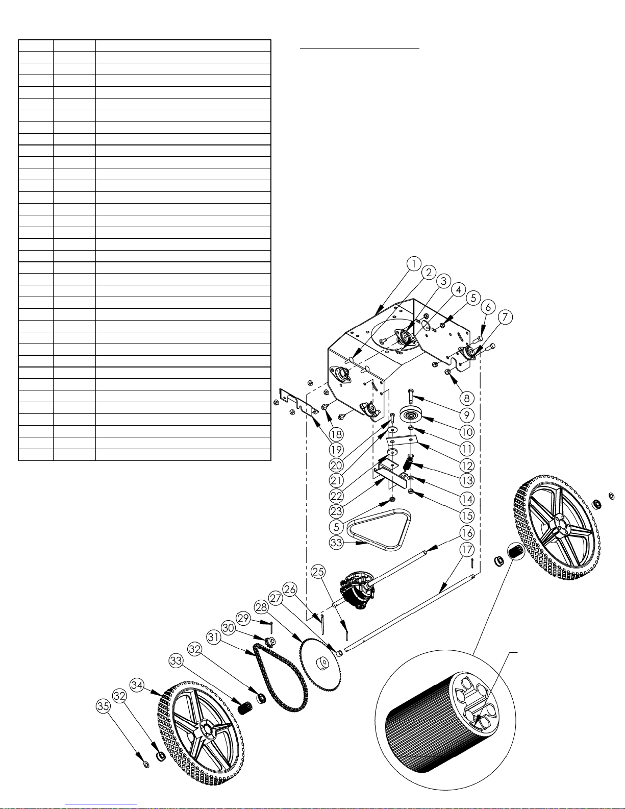
Drive Train Assembly
ITEM # PART # DESCRIPTION
1 19015* Motor Base - Upper, STP Trimmer
2 10197 Bolt - Carriage 5/16-18X1 GR5 ZY
3 19019 Bearing - 1/2" Flange Mounted
4 10216 Bolt - Carriage 5/16-18X3/4 GR5 ZY
5 NB170 Nut - Serr Flange 5/16-18 ZY
6 NB604 Bolt - 3/8-16 X 1 GR5 ZY
7 4005 Bearing - Side Flange
8 NB182 Nut - Nyloc 3/8-16 ZY
9 NB107 Bolt - 3/8-16 X 1 1/2 HCC GR5 ZY
10 T30V Pulley - Idler Clutch, 2 3/4 OD
11 NB174 Nut - Jam 3/8-16 ZY Grade 2
12 19024* Idler Arm - Transmission
13 7821 Latch Spring
14 NB272 Washer - SAE Flat 3/8 ZY
15 NB280 Nut - 2 Way Lock 3/8-16 ZY
16 19020 Transmission - String Trimmer
17 19025 Axle - Self-Propelled Trimmer
18 26X249 Screw - .312-18 x .75
19 19087* Guard - Chain; Trimmer
20 NB501 Bolt - 5/16-18 X 1 HCC GR5 ZY
21 NB579 Washer - Fender, 5/16 X 1 1/4 OD ZY
22 16823 Bushing - Shoulder 3/8, ZT60
23 19023* Bracket - Idler Arm, SP Trimmer
24 19053 Belt - 24", SP Trimmer
25 NB126 Pin - Cotter, 1/8 X 1
26 19036 Pin - Cotter, 3/16 X 2.25; ZP
27 690369 Spacer - 1/2" TO 17 MM
28 19022 Sprocket - No. 35, 60 Teeth; 1/2" Bore
29 19035 Pin - Cotter, 1/8 X 1-1/2; ZP
30 19021 Sprocket - No. 35, 10 Teeth; 1/2" Bore
31 19044 Chain - ANSI #35, 70 Link Loop
32 MWB Bearing - Wheel, 1 1/8"OD X 1/2"ID
33 19045*** Clutch - Wheel, 1.125 OD X 0.5 ID
34 19026** Wheel - 14", 1/2" Bearings; Trimmer
35 NB177 Washer - Mach 1/2 NR 14 GA
When ordering replacement parts
* Use paint code: TK=Black
** Wheels include two bearings. Use part # MWB when replacing bearings only.
Note: Optional wheel kits are available that include the bearings and wheel clutch
installed. Order part # 19085 for left wheel kit and part # 19086 for right wheel kit.
*** Wheel clutch must be installed in the correct orientation in order to operate
properly. Wheel clutch is installed correctly when wheels spin freely while
trimmer is moving forward without the engine running (wheels will have resistance
when trimmer is moving backward). One of the wheel bearings may need to be
removed prior to installing the wheel clutch. The wheel clutch has an arrow on the
side to indicate the “free-wheel” direction. Ensure clutch is orientated so the freewheel direction corresponds to direction the wheel will rotate while trimmer is
moving forward and press the clutch into the center of the wheel (interference fit).
Then replace the wheel bearing and install the wheel on the axle.
Important!Rotate wheel in free-wheel direction while mounting on axle
(spin and push at the same time). Ensure both wheel bearings remain fully
seated in wheel during wheel installation and operation. Failure to do so may
cause damage to wheel clutch.
Arrow on clutch
shows direction
wheel spins freely
when installed.
12
Page 13

OWNER’S
MANUAL
Visit us at: www.swisherinc.com
MODEL NO.
STP67522BS
Each trimmer has its own model number. Each engine has its
own model number. The model number for the trimmer will be
found on the left hand side of the motor base. The model
number for the engine will be found on the top of the blower
fan housing.
All trimmer parts listed herein may be ordered directly from
Swisher or your nearest Swisher dealer.
All engine parts may be ordered from the nearest dealer of the
engine supplied with your mower.
WHEN ORDERING PARTS, PLEASE HAVE THE
FOLLOWING INFORMATION AVAILABLE:
* PRODUCT – TRIMMER
* SERIAL NUMBER - _______________
* MODEL NUMBER - _______________
* ENGINE MODEL NUMBER - _______________
TYPE - _______________
* PART NUMBER WITH PAINT CODE
* PART DESCRIPTION
TELEPHONE - 1-800-222-8183
FAX - 1-660-747-8650
SWISHER ACQUISITION INC.
1602 CORPORATE DRIVE
WARRENSBURG, MO 64093
Changing your landscape since 1945.
13
Page 14

Visítenos en www.swisherinc.com
MANUAL DEL
Self-Propelled
PROPIETARIO
Número del modelo
Del número de serie
L215-335001
STP67522BS
IMPORTANTE
Lea y siga todas las
advertencias e instrucciones
sobre seguridad antes de
poner en funcionamiento
este equipo.
Easy Glide
Ensamblaje
Funcionamiento
Servicio y ajuste
Piezas para
reparación
1602 CORPORATE DRIVE, WARRENSBURG MISSOURI 64093
TELÉFONO 660-747-8183 FAX 660-747-8650
19129 REV 15-335
Hecho en
EE.UU.
de Estados Unidos y partes mundial
SWISHER ACQUISITION INC.
Page 15

GARANTÍA LIMITADA
La garantía que el fabricante otorga al comprador original es: Este producto está libre de defectos en los
materiales y la mano de obra por un periodo de dos (2) años desde la fecha de compra por parte del
comprador consumidor original. Repararemos o cambiaremos, a nuestra discreción, las partes que se
determine estén defectuosas debido a los materiales o a la mano de obra. Esta garantía está sujeta a las
siguientes limitaciones y exclusiones:
1) Garantía del motor Todos los motores que se utilizan en nuestros productos poseen una
garantía separada que las extiende el fabricante a cada motor.
Cualquier problema en el funcionamiento del motor es
responsabilidad del fabricante del motor y de ninguna manera
Swisher o sus agentes son responsables por la garantía del motor. El
teléfono de atención de Briggs & Stratton Engine Service Hot Line es
1-800-233-3723.
2) Uso Comercial Este producto no ha sido diseñado para uso comercial y no posee
garantía comercial.
3) Limitación Esta garantía se aplica sólo a los productos que se han ensamblado,
ajustado y operados correctamente de acuerdo con las instrucciones
contenidas en este manual. Esta garantía no se aplica a ningún
producto de Swisher que ha sido objeto de modificaciones, mal uso,
abuso, ensamblaje o instalación incorrectos, daños en el embarque, o
a un desgaste normal del producto.
4) Exclusiones Están excluidos de esta garantía el desgaste normal, los ajustes
normales y el mantenimiento normal.
En caso de que usted tenga un reclamo amparado por esta garantía, debe regresar el producto a un
representante de servicio autorizado. Todos los cargos de transporte, daños o pérdida que se produzcan
durante el transporte de las piezas suministradas para el cambio o reparación bajo esta garantía los
cubrirá el comprador. Si tiene preguntas relacionadas con esta garantía, por favor llámenos al número
gratis 1-800-222-8183. Antes de procesar cualquier reclamo cubierto por la garantía, necesitamos saber
el número del modelo, el número del serial y el nombre del distribuidor Swisher autorizado en donde
usted compró la podadora.
ESTA GARANTÍA NO SE APLICA A DAÑOS INCIDENTALES O CONSECUENCIALES Y
CUALQUIERA DE LAS GARANTÍAS IMPLÍCITAS SE LIMITAN AL MISMO PERIODO DE
TIEMPO ESTABLECIDO AQUÍ, PARA TODAS LAS GARANTÍAS EXPRESAS. Algunos estados
no permiten la limitación de los daños consecuenciales o las limitaciones en la duración de una garantía
implícita, así que las limitaciones o las exclusiones de arriba es posible que no apliquen para usted. Esta
garantía le otorga derechos legales específicos y usted puede tener otros derechos, los cuales varían de
un estado a otro. Esta es una garantía limitada de acuerdo a como se ha definido en la ley MagnusonMoss Act de 1975.
2
Page 16

Limpie el área de objetos tales como rocas, juguetes, etc., que pudieran ser arrojados
Pare el motor y revise cuidadosamente el daño y repárelo como sea necesario.
Instrucciones sobre seguridad
Este símbolo de alerta de seguridad indica mensajes importantes en
este manual. Cuando vea este símbolo, lea cuidadosamente el mensaje
que sigue y esté alerta a la posibilidad de lesiones personales
• Lea, comprenda y siga todas las instrucciones del manual y sobre la orilladora antes
de encenderla
• Lea cuidadosamente este manual. Familiarícese con los controles y cómo operar
correctamente la unidad.
• Sólo permita que los adultos responsables, que estén familiarizados con las
instrucciones operen la unidad.
•
por la unidad.
• Asegúrese de que no haya otras personas antes de hacer recortes. Detenga la
unidad si alguien entra al área.
• Esté alerta sobre la dirección de la descarga de la orilladora y no la dirija hacia nadie.
• No dirija la descarga de la orilladora hacia objetos rompibles, tales como ventanas,
etc.
• No ponga en funcionamiento la orilladora sin que tenga colocadas todas las
protecciones y pantallas.
• Nunca deje la máquina funcionando sin supervisión.
• Pode sólo bajo la luz del día o con buena luz artificial.
• No opere la orilladora mientras esté bajo la influencia del alcohol o de drogas.
• Tenga cuidado con el tráfico cuando esté operando cerca de vías de comunicación.
• Use la orilladora de acuerdo a lo proyectado por el fabricante y como se describe en
el manual.
• No ponga a funcionar la orilladora si se ha caído o está dañada de alguna forma.
Siempre haga que reparen los daños antes de ponerla a funcionar.
• Siempre use gafas de seguridad o protectores para los ojos cuando use la orilladora.
• Vístase adecuadamente. No opera la orilladora cuando esté descalzo o cuando use
sandalias abiertas. Use sólo zapatos sólidos para una buena tracción cuando esté
rebajando. Use camisas manga larga o chaquetas, también use pantalones largos.
No pode usando pantalones cortos.
• Mantenga los ojos y la mente en su orilladora y en el área que está podando.
• No permita que otros intereses lo distraigan.
• No coloque las manos y los pies cerca o debajo de las piezas rotatorias.
• Antes de limpiarla inspeccione o repare la orilladora, pare el motor y desconecte el
cable de la bujía y manténgalo lejos de la bujía para evitar un arranque accidental.
• No opere la orilladora si vibra anormalmente. La vibración excesiva es una señal de
daño.
• No ponga a funcionar la orilladora sobre grama húmeda, donde no sea posible una
pisada firme. Camine, nunca corra.
• Detenga la orilladora cuando cruce sobre sendas de grava, etc.
3
Page 17

Las pendientes son un factor principal relacionado
con
la p
érdida de
Funcionamiento en pendiente
•
•
control y de accidentes por resbalones, los cuales pueden ocasionar
lesiones graves. Todas las pendientes exigen mayor precaución. Si se
siente incómodo en una pendiente no realice la poda.
SÍ: Pode a través de la cara de una pendiente y no arriba y abajo
• SÍ: Quite los objetos tales como rocas, ramas de árboles, etc.
• SÍ: Esté pendiente de los agujeros, los surcos o los topes. El césped alto puede
esconder los obstáculos.
• NO: Pode cerca de declives, zanjas o terraplenes. El operador podría perder
apoyo o balance.
• NO: Pode en exceso las pendientes pronunciadas
• NO: Pode sobre el césped húmedo. La pisada sin apoyo podría ocasionar
resbalones.
Mantenga a los niños fuera del área y bajo la supervisión de otro adulto
responsable.
• Esté alerta y apague la máquina si los niños entran al área.
Niños
• Antes y cuando repase, observe hacia atrás y hacia abajo si hay niños.
• Nunca permita que los niños pongan a funcionar esta máquina.
• Tenga mayor cuidado cuando se aproxime a las esquinas ciegas, arbustos, árboles
o hacia otros objetos que puedan obstruir la visión.
Servicio
• Tenga mucho cuidado cuando manipule gasolina y otros combustibles. Son
inflamables y sus gases son explosivos.
• Use sólo un recipiente aprobado para el combustible.
• Nunca quite la tapa de la gasolina o añada combustible con el motor encendido.
• Permita que el motor se enfríe antes de agregarle más combustible. No fume.
• Nunca recargue de combustible la máquina en ambientes interiores.
• Nunca almacene la máquina o el recipiente de combustible donde haya una llama
abierta, tal como un calentador de agua.
• Nunca ponga a funcionar una máquina en un área cerrada.
• Mantenga las tuercas y los pernos roscados apretados y el equipo en buena
condición.
• Nunca interfiera los dispositivos de seguridad
• Mantenga la máquina libre de grama, hojas o de otras partículas. Limpie los
derrames de aceite y de combustible. Permita que la máquina se enfríe antes de
almacenarla.
• Detenga e inspeccione el equipo si golpea un objeto. Repárelo, si es necesario,
antes de volverlo a encender.
• Nunca haga reparaciones o ajustes con el motor encendido.
4
Page 18

Cuando está en funcionamiento, cualquier cortadora puede
Déle vuelta hacia arriba a los mangos y alinee el agujero
Los mangos se pueden ajustar hacia arriba y hacia abajo y hacia
chocar con objetos extraños que podrían ser lanzados a los ojos,
lo que podría causar lesiones graves. Siempre use lentes de
seguridad certificados o gafas de seguridad de visión amplia
sobre los anteojos, antes de fijar la vista en cualquier maquina
cortadora y mientras esté operando tal máquina.
El funcionamiento de cualquier cortadora produce ondas sonoras
que pueden dañar el oído humano. Se recomienda protección para
los oídos.
¡PRECAUCIÓN!
Pueden ocurrir accidentes trágicos si el operador no está alerta a la
presencia de los niños. Los niños, a menudo, se sienten atraídos por
las máquinas y por la actividad de podar. Nunca asuma que los
niños se quedarán donde usted los vióanteriormente.
No opere la orilladora si vibra anormalmente. La vibración excesiva
es una señal de daño. Pare el motor y revise con cuidado el daño y
repárelo como sea necesario.
Etiqueta de advertencia
19991
Las cajas contienen:
• Orilladora
Contenido de las piezas en bolsas:
• Manual
• Manual del motor
• Gafas de seguridad
• Botella de aceite de motor
• Línea cortadora
• llave hexagonal
Ensamblaje
Herramientas necesarias:
• Llave de 12,7 mm
Instalación de los mangos:
1. Quite los sujetadores sueltos de los mangos inferiores.
2.
inferior de los mangos con el agujero del marco de la
orilladora. Instale los accesorios que se quitaron en el
paso anterior. Ajuste, pero no apriete los pernos
roscados.
3. Enganche la empuñadura superior a la empuñadura
inferior con los botones y sujetadores incluidos con la
empuñadura inferior.
4. Ajuste los mangos para que funcionen cómodamente.
5. Apriete todos los pernos roscados.
adentro y hacia fuera para proporcionar un funcionamiento
cómodo.
Ajuste del mango
5
Page 19

Preparación de la unidad para uso por primera vez
• Llene el cárter del motor con aceite. Con esta unidad se ha suministrado un 20oz envase con
aceite. Una nueva unidad requiere 18-20oz. NO LO SOBRELLENE.
• Llene el tanque de combustible del motor con gasolina. LA GASOLINA DEBE
AGREGARSE EN EL EXTERIOR, EN UN ÁREA BIEN VENTILADA.
• Inspeccione para estar seguro de que la cuerda se ha instalado correctamente. Para realizar una
instalación correcta, se ha proporcionado un diagrama, y está exactamente arriba de el cabezal
de corte.
• Consulte el manual del fabricante del motor para especificaciones de combustible y aceite.
Instalación de la línea recortadora
¡Importante!
para la unidad, ocasionará atascamientos y mal funcionamiento.
Usan una cuerda de 45,7 cm
Compre la línea pre cortada P3618
• Doble con holgura la línea cortadora a la mitad.
• Inserte la línea a través de los agujeros inferiores del disco (Paso 1).
• Llevar extremos alrededor ya través de la ranura en la brida de disco (Paso 2).
• Hale los extremos para apretar el lazo (Paso 3).
Use la longitud adecuada de la línea. El uso de una línea demasiado larga
Paso 1
Paso 2 Paso 3
Posiciones del hilo de la bordeadora
Posiciones de ajuste del hilo de la bordeadora:
• La bordeadora cuenta con 4 puntos de ajuste del hilo.
• Para segar con la bordeadora, se recomienda utilizar la configuración con 4 hilos para
obtener un corte más parejo y uniforme.
• Para recortar vegetación larga o densa, se recomienda utilizar la configuración con 2 hilos,
para un mejor rendimiento.
Para ajustar la altura del corte:
1. Afloje el tornillo de fijación con la llave de cabeza hexagonal incluida.
2. Deslice el cabezal de corte hacia arriba o abajo, hasta la altura de corte deseada.
3. Apriete el tornillo de fijación.
4. Puede utilizarse cualquier altura de corte con cualquier configuración de hilos.
Configuración con 4 hilos
Se ilustra ajustada a una altura de corte baja
Tornillo
de fijación
Configuración con 2 hilos
6
Se ilustra ajustada a una altura de corte alta
Page 20

Operación
Importante: Para garantizar la correcta operación, limpie el motor y la bordeadora periódicamente.
Retire los restos acumulados en la parte superior del motor. Durante la operación, los residuos pueden
enroscarse en el cabezal de la bordeadora. El uso prolongado en este estado puede provocar un desgaste
excesivo y daños en las piezas. Apague la bordeadora y retire los residuos periódicamente.
Para arrancar la bordeadora:
1. Retire los residuos acumulados en el motor y el cabezal de la bordeadora.
2. Coloque el control del acelerador en la posición “FAST” (Rápido).
3. Sujete firmemente la empuñadura de la soga y jale lentamente hasta sentir resistencia. Luego, jale
rápidamente con una brazada completa.
4. Una vez que el motor arranque, deje el control del acelerador en la posición “FAST”. El control
del acelerador debe estar en la posición rápida para un máximo rendimiento.
5. Conecte el cabezal de corte.
6. Comience a recortar.
Para conectar/desconectar el cabezal de la bordeadora:
• Conexión: Jale el gancho de control hasta que haga contacto con la empuñadura superior y sujételo
junto con la empuñadura. Si el cabezal de la bordeadora no se conecta completamente, consulte la
sección de ajuste de la correa.
• Desconexión: Libere el gancho de control. El cabezal de la bordeadora debería detenerse en unos
segundos. De lo contrario, consulte la sección de ajuste de la correa.
Para activar/desactivar la transmisión:
• Activación: Jale la palanca de activación de la transmisión hasta que haga contacto con la
empuñadura superior y sujétela junto con la empuñadura.
• Desactivación: Libera la palanca de activación de la transmisión.
Para detener la bordeadora:
1. Libere el gancho de control.
2. Coloque la palanca de control del acelerador en la posición “SLOW” (Lento) durante unos
segundos y, luego, colóquela en la posición “STOP” (Detención).
Importante: Para una operación más segura, verifique que los residuos no salgan despedidos en
su dirección ni la de otras personas.
Solucion de problemas
• Si no se arranque el motor, quitar el filtro de aire para asegurarse que el
filtro y el carburador estan limpios.
Consejos para podar
• No levante la cabeza recortadora cuando esté podando. Deje que la cabeza descanse levemente,
tocando la tierra.
• Mantenga un ojo sobre la longitud de la línea recortadora. A medida que la línea se hace más corta
también se hace menos efectiva para cortar y llevará más tiempo para podar adecuadamente. Cambie
la línea cuando sea necesario. (Vea la instalación de la línea recortadora).
• No pode la grama húmeda.
• Tenga cuidado cuando recorte en pendientes.
• Use la longitud apropiada de la línea. El uso de una línea demasiado larga para la unidad, ocasionará
atascamientos y mal funcionamiento.
7
Page 21

ADVERTENCIA
-
SIEMPRE PARE EL MOTOR Y DESCONECTE EL CABLE
Mantenimiento de la orilladora
Las correa utilizadas para conectar/desconectar el cabezal de la bordeadora pueden ajustarse conforme a
Asegúrese de que la orilladora esté en buenas condiciones de trabajo, teniendo en mente las siguientes indicaciones
cada vez que use su orilladora.
• Mantenga la orilladora en buenas condiciones de funcionamiento y conserve todos los protectores y pantallas
en su lugar. NO opere esta orilladora si falta alguna de las pantallas o protectores.
• Revise que todos los sujetadores estén adaptados para mantener el equipo en una disposición segura de trabajo.
Haga los ajustes que sean necesarios.
• A fin de reducir los peligros de incendio, mantenga el motor libre de grama, hojas o de grasa excesiva.
• NO funcione la orilladora con un silenciador dañado o faltante.
• NO intervenga el sistema de escape; esto podría causar un peligroso incendio.
• NO funcione el motor si falta el purificador de aire o la cubierta colocada sobre la toma de aire del carburador.
La remoción de estas piezas podría crear un incendio peligroso.
• Antes de limpiar, hacer ajustes o reparaciones a la orilladora, PARE el motor, desconecte el cable de la bujía y
deje que el motor se enfríe.
• Manipule la gasolina con cuidado. NO fume o use gasolina cerca de llamas abiertas. Utilice sólo contenedores
de gasolina aprobados.
• Nunca añada combustible o arranque la orilladora en áreas poco ventiladas, tales como garajes o edificios de
servicios.
• Siempre vuelva a colocar la tapa al tanque de combustible. Asegúrese de limpiar cualquier gasolina derramada.
• No cambie los ajustes del gobernador del motor o le dé más velocidad al motor; se pueden originar lesiones o
daños graves.
• Nunca almacene la orilladora, con gasolina en el tanque, dentro de un edificio donde los gases puedan alcanzar
una llama abierta o chispas.
• Siempre permita que el motor se enfríe antes de almacenarlo.
NUNCA AÑADA GASOLINA A UN MOTOR CALIENTE – PERMITA QUE
EL MOTOR SE ENFRÍE ANTES DE AÑADIRLE GASOLINA.
DE LA BUJÍA ANTES DE EFECTUAR CUALQUIER AJUSTE O SERVICIO.
Motor
• Consulte el manual de servicio del motor incluido con este producto.
Correas
• Cada tanto, revise la correas para verificar que no presente desgaste.
Si está desgastada, reemplácela.
Ajuste de la correa
Durante las primeras horas de operación, todas las correas atraviesan un período de “rodaje”,
tras el cual muchas deben ajustarse conforme a las siguientes instrucciones. Algunas señales
que indican que las correas deben ajustarse son las siguientes:
• Pérdida de potencia del cabezal de corte, que hace que el cabezal gire inusualmente
lento o se detenga.
Ruedecilla
• Desgaste excesivo de la correa debido al deslizamiento.
• La correa que acciona la transmisión está diseñada para estar tensa constantemente y no debe ajustarse
más.
•
las siguientes instrucciones:
1. Ubique la ruedecilla de ajuste del cable de control (consulte la ilustración).
2. Libere el gancho de control para desconectar el cabezal de la bordeadora.
3. Gire la ruedecilla unas vueltas en sentido antihorario (desde la posición de operación normal).
4. Vuelva a conectar el cabezal de la bordeadora.
5. Si el cabezal de la bordeadora no funciona normalmente, repita los pasos 2 a 4.
Importante: No apriete excesivamente la ruedecilla de ajuste del cable. Puede provocar la rotura
del cable. NO debería necesitarse fuerza excesiva para accionar completamente el gancho de control.
8
Page 22

Reemplazo de la correa
Reemplazo de la correa de accionamiento del cabezal A
1. Retire la cubierta de la correa delantera.
2. Afloje o retire los sujetadores utilizados para enganchar el motor y permitir su movimiento. Deslice o incline el
motor de manera que la polea inferior del motor I se aleje de la transmisión y se genere un espacio que
permita retirar la correa.
3. Retire la correa desgastada.
4. Instale la nueva correa pasándola primero por debajo del motor y alrededor de la polea inferior del motor I .
5. Luego, pásela entre las dos poleas locas, como se ilustra en F .
6. Instale la correa alrededor de la polea delantera B .
7. Asegúrese de que la correa esté bien instalada entre las guías de la correa C y la polea adyacente.
8. Asegúrese de que la correa esté bien instalada en la ranura de cada polea.
9. Asegúrese de que la correa está encima de la parte superior del eje de la transmisión E .
10. Apriete o vuelva a colocar los sujetadores utilizados para enganchar el motor.
11. En caso de haberse ajustado previamente la tensión de la correa, restablezca la ruedecilla de ajuste girándola en
sentido horario hasta donde lo permita (consulte la ilustración de las instrucciones de ajuste de la correa). Si el
cabezal no se conecta correctamente, consulte las instrucciones de ajuste de la correa.
12. Vuelva a colocar la cubierta de la correa delantera.
Reemplazo de la correa de potencia de la transmisiónH
1. Retire la cubierta de la correa delantera.
2. Retire la correa de accionamiento del cabezal A conforme a las instrucciones anteriores.
3. Retire la correa desgastada.
4. Instale la nueva correa pasándola primero por debajo del motor y alrededor de la polea superior del motor J .
5. Luego, pase la correa alrededor de la polea de transmisión D .
6. Por último, pase la correa alrededor de la polea loca G . La polea loca es accionada por resorte, lo que puede
dificultar la última parte de la instalación de la correa. Para facilitar la instalación de la correa, empuje la polea
loca hacia la polea de transmisión mientras coloca la correa alrededor de la polea loca.
Peligro de pellizco:
Asegúrese de que ninguna parte de su cuerpo quede entre la correa y las poleas, ya que se
pueden provocar lesiones.
7. Vuelva a colocar la correa de accionamiento del cabezal conforme a las instrucciones anteriores.
8. Vuelva a colocar la cubierta de la correa delantera.
PRECAUCIÓN.
9
Page 23

Rueda derecha
elemento
pieza
elemento
pieza
Montaje
Ver detalle
Ver detalle
Página 12
Página 12
Rueda izquierda
Ver detalle
Página 11
N.º del
1 N/D Motor - Briggs & Stratton 15 2030 Perilla - Plástico negro
2 NB170 Tuerca - Acanalada 5/16-18 16 NB275 Arandela - Plana SAE 5/16
3 NB253 Perno - Acanalado, 5/16-18x1 1/4 17 NB180 Tuerca - Nyloc 1/4-20
4 19018 Polea - Accionamiento doble, bordeadora 18 19561 Apretón - Manilla, antivibraciones
5 NB271 Arandela - Plana USS 3/8, acero al carbono ZY 19 19005 Gancho - Bordeadora
6 NB607 Arandela - Belleville SP 20 19017* Empuñadura - Superior, bordeadora SP
7 NB238N Perno - HHC 3/8-24 X 1 21 NB218 Perno - 1/4-20 X 2 HCC GR5 ZY
8 2019 Protector - Correa 22 NB587 Perno - Cabeza de hongo, 5/16-18 X 1 3/4
9 19135 Sujeción - Panel 23 10399* Empuñadura - Inferior
10 9030 Chaveta - 3/16 X 1 24 NB596 Perno - Acanalado, 5/16-18 X 3/4
11 19027 Palanca - Activación de la transmisión 25 26X249 Tornillo - 0.312-18 X 0.75
12 19823 Palanca Apretón 26 19016* Cubierta - Posterior, bordeadora SP
13 19101 Cable - Control de transmisión; STP 27 19034 Correa - 60 in, bordeadora
14 19006 Cable - Control, bordeadora 28 2006* Base - Motor inferior
N.º de
Descripción
N.º del
29 19004 Protección - Caucho
N.º de
Descripción
Para realizar pedidos de repuestos
* USE EL CÓDIGO DE PINTURA: TK=NEGRO
10
Page 24

Montaje del cabezal de la bordeadora
N.º del
elemento
Para realizar pedidos de repuestos
* USE EL CÓDIGO DE PINTURA:
TK=NEGRO
N.º de
pieza
1 18999* Pieza soldada - Cuello de la bordeadora, estándar
2 NB138 Perno - 5/16-18 X 2 1/2 HCC GR5 ZY
3 NB170 Tuerca - Acanalada 5/16-18 ZY Carcasa Hrd
4 NB595 Tuerca - Obstrucción, 5/8-11, reversible
5 2049 Polea - Álabe de 4.5 in
6 NB149 Arandela - 5/8 de diám. int. X 1, 14 de diám ext. GA ZY
7 B985/8 Rodamiento - Bordeadora
8 19123 Rodamiento - 20 mm de diám. int, sello de acero
9 19009 Árbol - Cabezal de corte, estándar
10 NB560 Perno - 1/4-20 X 1 1/4 HCC GR5 ZY
11 19011 Buje - Cabezal de corte, PM
12 NB312 Tornillo - Fijación 5/16-18 X 1/2 con Loctite
13 19010 Protector - Árbol, bordeadora
14 19837* Disco del cabezal de corte
15 NB180 Tuerca - Nyloc 1/4-20
16 NB779 Tuerca - Acanalada, hex. ZY 3/8-16
17 18823 Arandela - Plana, 1/2 in de diám int.-12GA ASTM A325; ZY
18 19012* Guía de corte - Bordeadora
19 10501 Perno de cabeza de hongo de 3/8 X 1-1/4
20 NB107 Perno - 3/8-16 X 1 1/2 HCC GR5 ZY
21 T30V Polea - Embrague de polea loca, 2 3/4 de diám. ext.
22 NB579 Arandela - Defensa, 5/16 X 1 1/4 de diám. ext. ZY GR2
23 NB212 Tuerca - HNC, 3/8-16 GR2 ZY
24 19014* Brazo secundario libre - Bordeadora STP
25 NB280 Tuerca - Reversible de bloqueo 3/8-16 ZY y cera Gr A
26 NB181 Tuerca - Nyloc 5/16-18 ZY
27 19108 Polea - Polea loca de la parte posterior, 2.25 in 3/8 in de diám. ext.
28 NB278 Perno - 1/4-20 X 1 3/4 GR2 ZY
29 NB501 Perno - 5/16-18 X 1 HCC GR5 ZY
30 NB524 Tuerca - Acanalada, 1/4-20 grado 5 ZY
31 16823 Casquillo - Arcén 3/8, ZT60
32 2042 Protector - Hilo
33 26X249 Tornillo - 0.312-18 X 0.75
DESCRIPCIÓN
11
Page 25

elemento
pieza
DESCRIPCIÓN
3
19019
Rodamiento - 1/2 in, montado sobre una base
6
NB604
Perno - 3/8-16 X 1 GR5 ZY
9
NB107
Perno - 3/8-16 X 1 1/2 HCC GR5 ZY
10
T30V
12
19024*
Brazo secundario libre - Transmisión
15
NB280
Tuerca - Reversible de bloqueo 3/8-16 ZY
18
26X249
Tornillo - 0.312-18 X 0.75
21
NB579
Arandela - Defensa, 5/16 X 1 1/4 de diám. ext.
24
19053
Correa - 24 in, bordeadora SP
27
690369
Separador - 1/2 in a 17 mm
28
19022
30
19021
Rueda dentada - N.º 35, 10 dientes; orificio de
1/2 in de diám. int.
34
19026**
Rueda - 14 in, rodamientos de 1/2 in;
Montaje del sistema de tracción
N.º del
11 NB174 Tuerca - Obstrucción 3/8-16 ZY Grado 2
13 7821 Resorte sujetador
14 NB272 Arandela - Plana SAE 3/8 ZY
16 19020 Transmisión - Bordeadora de hilo
17 19025 Eje - Bordeadora autopropulsada
19 19087* Protector - Cadena, bordeadora
20 NB501 Perno - 5/16-18 X 1 HCC GR5 ZY
22 16823 Casquillo - Arcén 3/8, ZT60
23 19023* Ménsula - Brazo secundario libre, bordeadora
25 NB126 Pasador- De aletas, 1/8 X 1
26 19036 Pasador- De aletas, 3/16 X 2.25; ZP
N.º de
1 19015* Base del motor - Superior, bordeadora STP
2 10197 Perno - Cabeza de hongo 5/16-18X1 GR5 ZY
4 10216 Perno - Cabeza de hongo 5/16-18X3/4 GR5 ZY
5 NB170 Tuerca - Acanalada 5/16-18 ZY
7 4005 Rodamiento - Brida lateral
8 NB182 Tuerca - Nyloc 3/8-16 ZY
Polea - Embrague de polea loca, 2 3/4 de
Para realizar pedidos de repuestos
* Use el código de pintura: TK=Negro
** Las ruedes incluyen dos rodamientos. Utilice el número de pieza MWB para
reemplazar solo los rodamientos.
Nota: Se ofrecen conjuntos de ruedas opcionales que vienen con los rodamientos y el
embrague de rueda instalado. Solicite el número de pieza 19085 si necesita el conjunto
de la rueda izquierda y el número de pieza 19086 para el conjunto de rueda derecha.
*** El embrague de rueda debe instalarse con la orientación correcta para que funcione
bien. Si el embrague de rueda está bien instalado, las ruedas giran libremente cuando
la bordeadora avanza con el motor apagado (las ruedas tendrán resistencia cuando la
bordeadora retrocede). Es posible que deba retirar el rodamiento de una de las ruedas
antes de instalar el embrague de rueda. El embrague de rueda posee una flecha en el
lateral para indicar la dirección de “rueda libre”. Asegúrese de que el embrague esté
orientado de manera tal que la dirección de rueda libre coincida con la dirección en la
que deberá girar la rueda cuando la bordeadora avance, y presione el embrague para
introducirlo en el centro de la rueda (ajuste con apriete). Luego, reemplace el
rodamiento de la rueda e instale la rueda en el eje.
Importante:Rote la rueda en la dirección de rueda libre durante el montaje
del eje (gire y empuje al mismo tiempo). Asegúrese de que los rodamientos de
ambas ruedas permanezcan completamente fijados durante la instalación de las
ruedas y la operación. De no hacerlo, podría dañarse el embrague de rueda.
Rueda dentada - N.º 35, 60 dientes; orificio de
29 19035 Pasador- De aletas, 1/8 X 1-1/2; ZP
31 19044 Cadena - ANSI 35, 70 eslabones cerrados
32 MWB
33 19045***
35 NB177 Arandela - Mach 1/2 NR 14 GA
Rodamiento - Rueda, 1 1/8 in de diám. ext. X
Embrague - Rueda, 1.125 de diám. ext. X 0.5
de diám. int.
La flecha del
embrague indica la
dirección en la que
la rueda gira
libremente cuando
está instalada.
12
Page 26

MANUAL DEL
PROPIETARIO
Visítenos en www.swisherinc.com
NÚMERO DEL
MODELO
STP67522BS
Cada orilladora tiene su propio número de modelo. Cada motor
tiene su propio número de modelo. El número de modelo de la
orilladora se encuentra en el lado izquierdo de la base del
motor. El número de modelo del motor se encuentra en la parte
superior de la caja del ventilador soplador.
Todas las piezas de la orilladora listadas aquí se pueden
ordenar directamente a Swisher o al distribuidor Swisher más
cercano.
Todas las piezas del motor suministrado con su podadora se
pueden ordenar al distribuidor del motor más cercano.
CUANDO ORDENE LAS PIEZAS, POR FAVOR
TENGA DISPONIBLE LA SIGUIENTE INFORMACIÓN:
* PRODUCTO-ORILLADORA
* NÚMERO DE SERIE- _______________
* NÚMERO DEL MODELO- _______________
* NÚMERO DE MODELO DEL MOTOR- _______________
TIPO - _______________
* NÚMERO DE LA PIEZA CON CÓDIGO DE LA PINTURA
* DESCRPCIÓN DE LA PIEZA
TELÉFONO - 1-800-222-8183
FAX - 1-660-747-8650
SWISHER ACQUISITION INC.
1602 CORPORATE DRIVE
WARRENSBURG, MO 64093
Modificando su paisaje desde 1945.
13
Page 27

Rendez-nous visite à : www.swisherinc.com
MANUEL DU
Self-Propelled
PROPRIÉTAIRE
Numéro de modèle
A partir du no de série L215-335001
STP67522BS
IMPORTANT
Avant de mettre en marche
cet équipement, lire le
présent manuel et suivre
toutes les directives de
sécurité indiquées.
Easy Glide
Assemblage
Utilisation
Réglage et entretien
Pièces de rechange
1602 CORPORATE DRIVE, WARRENSBURG MISSOURI 64093
TÉLÉPHONE 660-747-8183 TÉLÉCOPIEUR 660-747-8650
19129 REV 15-335
Fabriqué aux
ÉTATS-UNIS
des États-Unis et Pièces mondiaux
SWISHER ACQUISITION INC.
Page 28

GARANTIE LIMITÉE
Garantie du fabricant au consommateur acheteur original : Ce produit est garanti au consommateur acheteur
d'origine contre toute défectuosité de matériel et de main d'œuvre sur une période de deux (2) ans de la date
d'achat. Nous réparerons ou remplacerons, selon notre décision, les pièces trouvées défectueuses pour cause
de défaut de matériel ou de main-d'œuvre. La présente garantie est sujette aux limites et exclusions
suivantes :
1) Garantie du moteur Tous les moteurs utilisés dans nos produits sont couverts par une
garantie séparée attribuée par leurs fabricants individuels. Tout
problème à ce niveau est la responsabilité du fabricant et d'aucune façon
Swisher ou ses agents représentants ne pourront être tenus responsables
des problèmes sous garantie des moteurs. Ligne d'assistance pour
moteurs Briggs & Stratton : 1-800-233-3723.
2) Usage commercial Cet équipement n'est pas prévu pour usage commercial et n'est couvert
d'aucune garantie dans ce cas.
3) Limites La présente garantie s'applique seulement aux équipements adéquatement
assemblés, réglés et utilisés selon les directives comprises dans le
présent manuel. La présente garantie ne s'applique à aucun équipement
qui a été assujetti à toute modification, mauvaise utilisation, abus,
assemblage ou installation inadéquat, endommagement de transit ou à
l'usure normale du produit.
4) Exclusions Sont exclus de la présente garantie, l'usure. les réglages et l'entretien
normaux.
Pour toute réclamation de garantie, l'équipement ou la pièce défectueuse devra être retourné à un
concessionnaire de service autorisé. Toute responsabilité de perte dommages et frais d'expédition relatifs
aux retours pour réparation ou remplacements sous garantie demeureront à la charge du propriétaire. Pour
toute question relative à la présente garantie, veuillez communiquer avec nous au numéro sans frais 1-800222-8183. Pour pouvoir appliquer la garantie, les numéros de modèle et de série, la date d'achat et le nom
du dépositaire Swisher autorité duquel l'équipement a été acheté seront requis.
LA PRÉSENTE GARANTIE NE S'APPLIQUE À AUCUN DOMMAGE D'INCIDENCE OU DE
CONSÉQUENCE ET TOUTE GARANTIE DE MARCHANDISAGE IMPLICITE SERA LIMITÉE À LA
MÊME DURÉE QUE CELLE INDIQUÉE AUX PRÉSENTES, ET CE POUR TOUTE GARANTIE
EXPRIMÉE DE FAÇON EXPRESSE. Certains États ou provinces ne permettent pas d'exception des
dommages de conséquence ou de limite à la période de validité des garanties implicites, alors les limites et
exclusions ci-dessus peuvent ne pas s'appliquer dans votre cas. La présente garantie vous donne des droits
particuliers et il se peut que vous ayez d'autres droits qui varient d'un État ou d'une province à l'autre. La
présente est une garantie limitée tel que défini par la loi américaine Magnuson-Moss de 1975.
2
Page 29

Directives de sécurité
Ce symbole d'alerte de sécurité indique d'importants messages tout
au long du présent manuel. Lorsque rencontré, lisez attentivement
le message indiqué et demeurez sur vos gardes pour éviter toute
blessure possible.
3
Page 30

Utilisation sur des pentes
•
•
RECOMMANDATION : évoluer d'un côté à l'autre de la pente et non de haut en bas.
• RECOMMANDATION : retirer les objets tel que caillous, branches d'arbres, etc. avant de
commencer.
• RECOMMANDATION : prendre garde aux dépressions, monticules ou décompositions
organiques. Les hautes herbes peuvent cacher des obstacles.
• CONTRE-INDICATION : travailler près des fossés, remblais ou précipices ou autres
zones à fort risque de perdre pied ou l'équilibre.
• CONTRE-INDICATION : travailles sur des pentes abruptes
• CONTRE-INDICATION : travailler sur du gazon mouillé pour cause de danger de glisser.
Enfants
Gardez les enfants hors de la zone de travail et sous la surveillance d'un autre adulte
responsable.
• Demeurez alerte et arrêtez la machine si des enfants s'introduisent dans la zone de
travail.
• Avant de reculer et lorsque vous y procédez, regardez vers le sol derrière vous au cas
d'approche de petits enfants.
• Ne jamais laisser d'enfants faire fonctionner cette machine.
• Redoublez de prudence à l'approche d'aires hors de vue tel les coins de mur, derrière
les broussailles ou les arbres ou autre objets obstruant la vue.
Entretien
• Redoublez de prudents lors de l'utilisation d'essence ou autres carburants. Ceux-ci sont
inflammables et leurs émanations sont explosives.
• Ne les conservez que dans des contenants approuvés pour le carburant.
• Ne jamais retirer le bouchon du réservoir d'essence lorsque le moteur est en marche.
• Laissez refroidir le moteur avant de faire le plein d'essence. Ne pas fumer en faisant le plein
d'essence.
• Ne jamais faire le plein d'essence de la machine à l'intérieur.
• Ne jamais entreposer la machine ou un contenant d'essence près d'une flamme ou source
d'étincelles (chauffe-eau au gaz, outils électriques ou autres).
• Ne jamais faire fonctionner la machine dans un lieu clos.
• Gardez tous les écrous et boulons serrés et l'équipement en bon état.
• Ne jamais désaffecter les dispositifs de sécurité.
• Gardez la machine libre de toute accumulation de gazon, de feuilles ou d'autres débris.
Nettoyez les déversements d'essence et d'huile. - Laissez refroidir le moteur avant de faire le
plein d'essence.
• Si vous frappez un obstacle, arrêtez et inspectez la machine. Faites les réparations
nécessaires avant de redémarrer.
• Ne jamais faire de réglage ou réparation lorsque le moteur est en marche.
4
Page 31

La lame rotative de toute tondeuse peut venir en contact avec des
llerie retirée à l'étape précédente.
objets étrangers pouvant être projetés dans les yeux causant de graves
blessures. Avant de démarrer et durant le fonctionnement de toute
machine de tonte, portez toujours des lunettes de sécurité ou coquilles
par dessus vos verres de prescription qui sont homologuées pour
protéger tous les angles d'arrivée de particules.
Le fonctionnement de toute tondeuse produit une pression sonore
dommageable à l'ouïe humaine. Protection auditive recommandée.
MISE EN GARDE!
Un accident tragique peut se produire si l'opérateur n'est pas alerte en
présence d'enfants. Les machines et les activités engendrées sont
souvent une source d'intérêt pour les enfants. N'assumez jamais que
les enfants demeureront où vous les avez vus la minute précédente.
Ne vous servez pas du coupe-bordure s'il vibre de façon exagérée.
Ceci serait l'indication d'une pièce endommagée. Arrêtez le moteur et,
en prenant les précautions nécessaires, vérifiez les dommages et
effectuez les réparations requises.
Attention décalque
19991
Contenu de la boîte:
• Coupe-bordure
Sac de pièces comprenant:
• Manuel
• Manuel du moteur
• Coquilles de
protection oculaire
• Contenant d'huile
moteur
• Fil de coupe
• Clé hexagonale
Assemblage
Outils requis:
• Clé ½ po (13 mm)
Installation de la poignée:
1. Retirez les attaches lâches de la partie inférieure de la
poignée.
2. Faites pivoter la poignée vers le haut et alignez son
trou inférieur au trou du bâti du coupe- bordure.
Réinstallez la quincai
Seulement serrer les boulons légèrement à la main.
3. Fixer la poignée supérieure à la partie inférieure du
manche à l'aide des boutons et attaches fournies avec
la poignée inférieure.
4. Réglez la position de la poignée pour pour travailler
confortablement.
5. Serrez tous les boulons.
Pour un positionnement ergonomique, l'angle et la longueur
de la poignée sont réglables.
Réglage de la poignée
5
Page 32

Préparation pour la première utilisation
N
• Remplissez le carter du moteur d'huile. Un 20oz. contenant d'huile est fourni avec cette machine.
Une nouvelle unité nécessite 18-20oz. NE PAS EXCÉDER LE NIVEAU REQUIS.
• Remplissez le réservoir à essence. LE REMPLISSAGE DOIT ÊTRE FAIT À L'EXTÉRIEUR OU
DANS UN ENDROIT BIEN AÉRÉ.
• Confirmez que l'installation du fil est conforme au schéma apposé juste au-dessus la tête de coupe.
• Reportez-vous au manuel du fabricant de moteur pour les spécifications d'huile et de carburant.
Installation du fil de coupe
Important! Gardez le fil à une longueur adéquate. Un fil trop long causera un fonctionnement erratique
et le calage du moteur.
Utilisez un fil de 46 cm (18 po)
o
de pièce de fil pré-dimensionné P3618
• Repliez le fil de coupe en deux de façon lâche.
• Insérez ligne à travers les trous inférieurs du disque (Étape 1).
• Ramener les extrémités autour et à travers la fente dans la bride de disque (Étape 2).
• Tirez les bouts pour serrer le fil (Étape 3).
Étape 1
Étape 2
Étape 3
Positions des fils du taille-bordure
Positions des fixations des fils du taille-bordure
• Le taille-bordure est équipé de 4 points de fixation des fils.
• En coupant avec le taille-bordure, la configuration à 4 lignes de coupe est recommandée pour une
coupe plus cohérente et régulière.
• Lorsque vous coupez une végétation haute ou épaisse, la configuration à 2 lignes de coupe est
recommandée pour des performances améliorées.
Pour ajuster la hauteur de coupe :
1. Desserrez la vis de réglage à l'aide de la clé hexagonale fournie.
2. Faites glisser la tête de coupe vers le haut ou vers le bas selon la hauteur de coupe désirée.
3. Serrez la vis de réglage.
4. Toute hauteur de coupe est activable avec une des configurations de ligne de coupe.
Placez la vis
de réglage
Configuration de coupe à 4 lignes
Ensemble montré à une hauteur
de coupe peu élevés
Configuration de coupe à 2 lignes
Ensemble montré à une hauteur de
6
coupe élevée
Page 33

Fonctionnement
Important !
Pour assurer un bon fonctionnement, nettoyez régulièrement le moteur et le taille-bordure.
Retirez toute accumulation de paille du haut du moteur. Au cours de l'opération, des débris peuvent venir
s'enrouler autour de la tête de coupe. Une utilisation prolongée dans cet état peut entraîner une usure
excessive et des défaillance de la pièce. Périodiquement, éteignez le taille-bordure et retirez les débris.
Pour démarrer le taille-bordure :
1. Retirez tout débris accumulés du moteur et de la tête de coupe.
2. Déplacez la manette de commande sur « FAST » (rapide).
3. Saisissez fermement la poignée de corde et tirez lentement jusqu'à ce qu'une résistance se fasse sentir.
[X]Puis tirez rapidement de tout le bras.
4. Lorsque le moteur démarre, laissez manette sur « FAST ». La commande des gaz doit être définie en
position rapide pour des performances maximales.
5. Engagez la tête de coupe.
6. Commencez la coupe.
Engager/dégager la tête de coupe :
• Engager : Amenez l'étrier de contrôle en contact avec la poignée supérieure et saisissez-le en même
temps que la poignée. Si la tête de coupe ne s'engage pas complètement, reportez-vous à la section
Réglage de la courroie.
• Désengager : Relâchez l'étrier de contrôle. La tête de coupe doit s'arrêter en quelques secondes. Si la
Pour engager/désengager la transmission :
• Engager : Amenez le levier d'engagement de la transmission en contact avec la poignée supérieure et
• Désengager : Libérez le levier d'engagement de transmission.
Pour arrêter le taille-bordure :
1. Relâchez l'étrier de contrôle.
2. Placez le levier de commande de gaz sur le moteur à « SLOW » (lent) pendant quelques secondes, puis
tête de coupe ne se désengage pas complètement, reportez-vous à la section Réglage de la courroie.
saisissez-le en même temps que la poignée.
passer à « STOP » (arrêt).
Important! Pour un fonctionnement sûr, assurez-vous que es débris sont dirigés loin de vous et des
autres.
Dépannage
• Si le moteur ne démarre pas, retirez le filtre à air pour inspection et vous assurer
qu'il est propre, ainsi que carburateur
Conseils pour coupe-bordure
• Ne pas soulever la tête du coupe-bordure lors du travail. Laissez-la reposer légèrement contre le
sol.
• Gardez un œil sur la longueur du fil de coupe. Lorsque celui-ci devient plus court son efficacité est
réduite et il sera plus long de faire une bonne coupe. Au besoin, replacer le fil à une bonne longueur
(se référer à Installation du fil de coupe).
• Ne pas utiliser sur gazon mouillé.
• Pour le travail en pente, redoublez de prudence.
• Gardez le fil à une longueur adéquate. Un fil trop long causera une coupe inégale et le calage du
moteur.
7
Page 34

Entretien du coupe-bordure
AVERTISSEMENT
–
TOUJOURS ARRÊTER LE MOTEUR ET DÉCONNECTER LE
NE JAMAIS FAIRE LE PLEIN D'ESSENCE LORSQUE LE MOTEUR EST
Assurez-vous que votre coupe-bordure est en bonne condition de marche en suivant les directives ci-dessous en tête.
• Garder le coupe-bordure en bon état de marche et tous les écrans et gardes en place. NE PAS faire fonctionner le
coupe-bordure si l'un ou l'autre des écrans ou gardes est absent.
• Vérifiez le serrage de tous les écrous et boulons pour conserver l'équipement dans un état de marche sécuritaire.
Faites les réglages requis.
• Gardez le moteur libre de paillettes d'herbe, de feuilles ou d'excès de graisse pour prévenir tout danger d'incendie.
• NE PAS faire fonctionner le coupe-bordure si son silencieux est endommagé ou absent. NE PAS modifier le
système d'échappement, ceci pourrait créer un risque d'incendie.
• NE PAS faire fonctionner le moteur si le filtre ou le couvercle au-dessus du carburateur est absent. Le retrait des
ces pièces pourrait créer un danger d'incendie.
• ARRÊTER le moteur, débrancher la bougie et laisser refroidir le moteur avant de faire tout réglage ou réparation
du coupe-bordure.
• Manipulez l'essence avec précautions. NE PAS fumer ou utiliser de chalumeau ou outils pouvant créer des
étincelles près du contenant/réservoir d'essence. - N'utilisez que des contenants approuvés. Ne jamais faire
fonctionner un coupe-bordure dans un endroit sans aération adéquate tel un garage ou édifice d'entretien.
• Ne retirer le bouchon du réservoir que pour le remplissage. Assurez-vous de nettoyer tout déversement d'essence.
• Ne pas faire fonctionner le moteur à un régime excessif ou changer le réglage du gouverneur de vitesse, ceci
pourrait conduire à un bris mécanique ou des blessures graves.
• Ne jamais entreposer le coupe-gazon avec de l'essence dans le réservoir à l'intérieur d'un édifice où la possibilité
d'émanations pourraient atteindre un pilote de brûleur à gaz allumé ou une source d'étincelles. - Laissez toujours
refroidir le moteur avant de la remiser.
CHAUD – LAISSER REFROIDIR LE MOTEUR AVANT LE REMPLISSAGE
FIL DE BOUGIE AVANT DE FAIRE TOUT RÉGLAGE OU ENTRETIEN
Moteur
• Se référer au manuel d'entretien moteur fourni avec cet équipement.
Courroies
• Vérifiez occasionnellement la courroie pour usure. Une courroies usée doit être remplacée.
Réglage de la courroie
Pendant les premières heures de fonctionnement toutes les courroies traversent une « période de
rodage », après quoi les courroies doivent être ajustées en se référant aux instructions suivantes.
Les indications en faveur de l'ajustement des courroies incluent :
• La perte de puissance de la tête de coupe, causant une rotation anormale de la tête ou un
ralentissement.
• Une usure excessive de la courroie en raison du glissement.
• La courroie qui alimente la transmission est conçue pour être sous une tension constante et ne
nécessité aucun autre réglage.
• Les courroie utilisées pour engager/désengager la tête de coupe peuvent être ajustées en vous
référant aux instructions suivantes:
1. Localiser l'ajusteur de molette sur la câble de commande (voir illustration).
2. Sortez l'étrier de contrôle pour dégager la tête de coupe.
3. Faites pivoter la molette de quelques tours dans le sens des aiguilles d'une montre (à partir
de la position normale de fonctionnement).
4. Ré-engagez la tête de coupe.
5. Si la tête de coupe n'est pas revenue à son fonctionnement normal, répétez les étapes 2 à 4.
Molette !
Important ! Ne serrez pas trop les réglage du câble d'ajustement. Cela peut entraîner la cassure
du câble. Une force excessive ne doit PAS être nécessaire pour engager complètement l'étrier.
8
Page 35

Remplacement de la courroie
Remplacement de la courroie d'engagement de la tête A
1. Retirez le carter de la courroie avant.
2. Desserrez ou retirez les éléments de fixation utilisés pour attacher le moteur afin de permettre le déplacement du
moteur. Faites glisser ou inclinez le moteur de sorte que la poulie moteur inférieure I s'éloigne de la transmission, en
créant un écart pour permettre à la courroie d'être retirée.
3. Retirez l'ancienne courroie.
4. Installez la nouvelle courroie en passant tout d'abord la courroie sous le moteur puis autour de la poulie moteur
inférieure I .
5. Puis passez la courroie entre les deux poulies de renvoi comme indiqué en F .
6. Installer la courroie autour de la poulie avant B .
7. Veillez à ce que cette courroie soit correctement installée entre les guides-sangles C et la poulie adjacente.
8. Veillez à ce que cette courroie soit correctement installée dans le sillon de chaque poulie.
9. Veillez à ce que la courroie soit au-dessus de l'axe de transmission E .
10. Serrez ou réinstaller les fixations pour fixer le moteur.
11. Si la tension de la courroie avait précédemment été ajustée, réinitialisez la molette d'ajustement en faisant pivoter la
molette dans le sens des aiguilles d'une montre autant que le dispositif de réglage le permettra (reportez-vous
l'illustration dans les instructions de Réglage de courroie). Si la tête ne s'engage pas correctement, reportez-vous aux
instructions de Réglage de courroie.
12. Réinstaller le carter de la courroie avant.
Remplacement de la courroie H de transmission de puissance
1. Retirez le carter de la courroie avant.
2. Retirez la courroie A d'engagement de la tête selon les instructions fournies ci-dessus.
3. Retirez l'ancienne courroie.
4. Installez la nouvelle courroie en passant tout d'abord la courroie sous le moteur puis autour de la poulie moteur
supérieure J .
5. Ensuite, passez la courroie autour de la poulie de transmission D .
6. Pour terminer, passez la courroie autour de poulie arrière G . La poulie est à ressort, ce qui rend difficile de terminer
l'installation de la courroie. Pour faciliter l'installation, poussez la poulie vers la poulie de transmission tout en
enveloppant la courroie autour de de la poulie. ATTENTION – risque de pincement : Veillez à ne pas exposer une
partie du corps entre la courroie et les poulies, car cela pourrait causer des blessures.
7. Réinstaller la courroie d'engagement de la tête selon les instructions fournies ci-dessus.
8. Réinstaller le carter de la courroie avant.
9
Page 36

Ensemble[Assemblage]
Roue droite
Voir détail
Page 12
Roue gauche
Voir détail
Page 11
Élément N° Pièce N° Description Élément N° Pièce N° Description
1 N/D Moteur - Briggs & Stratton 15 2030 Bouton - plastique noir
2 NB170 Écrou - bride à face striée 5/16 à 18 16 NB275 Rondelle - SAE plate 5/16
3 NB253 Écrou - rebord dentelé 5/16 à 18 x 1 1/4 17 NB180 Écrou - Nyloc 1/4 à 20
4 19018 Poulie - Double disque, taille-bordure 18 19561 Grip - Poignée anti-vibrations
5 NB271 Rondelle - USS plate 3/8, ZY acier 19 19005 Étrier - taille-bordure
6 NB607 Rondelle - SP Bellville 20 19017* Poignée - Top, taille-bordure SP
7 NB238N Boulon - HHC 3/8 à 24 X 1 21 NB218 Boulon - 1/4-20 X 2 HCC GR5 ZY
8 2019 Garde - courroie 22 NB587 Boulon - carrosserie, 5/16 à 18 X 1 3/4
9 19135 Clip - panneau 23 10399* Poignée - basse
10 9030 Clavette en barre - 3/16 X 1 24 NB596 Écrou - rebord dentelé 5/16 à 18 x 3/4
11 19027 Levier - Engagement de Transmission 25 26X249 Vis - 0.312 à 18 X 0.75
12 19823 Levier Grip 26 19016* Couverture - arrière, taille-bordure SP
13 19101 Câble - Commande de transmission; STP 27 19034 Courroie - 60 po, taille-bordure
14 19006 Câble - Commande, taille-bordure 28 2006* Bloc - moteur inférieur
29 19004 Bouclier - caoutchouc
Lorsque vous commandez des pièces de rechange
* UTILISER LE CODE PEINTURE : TK = NOIR
10
Page 37

Ensemble tête de taille-bordure
Lorsque vous commandez des pièces de rechange
* UTILISER LE CODE PEINTURE : TK = NOIR
ÉLÉMENT N° PIÈCE N° DESCRIPTION
1 18999*
2 NB138
3 NB170
4 NB595
5 2049
6 NB149
7 B985/8
8 19123
9 19009
10 NB560
11 19011
12 NB312
13 19010
14 19837*
15 NB180
16 NB779
17 18823
18 19012*
19 10501
20 NB107
21 T30V
22 NB579
23 NB212
24 19014*
25 NB280
26 NB181
27 19108
28 NB278
29 NB501
30 NB524
31 16823
32 2042
33 26X249
Ensemble soudé - Col du taille-bordure, standard
Boulon - 5/16 à 18 X 2 HCC GR5 ZY
Écrou - Bride à face striée 5/16 à 18 compartiment ZY Hrd
Écrou - de blocage, 2 5/8 à 11 voie
Poulie - lame de 4,5 po
Rondelle - 5/8 diamètre intérieur 1 diamètre extérieur 14 GA ZY
Roulement - taille-bordure
Roulement - 20mm ID, joint acier
Arbre - Tête de coupe, standard
Boulon - 1/4 à 20 X 1 1/4 HCC GR5 ZY
Moyeu - Tête de coupe, PM
Vis - Ensemble de 5/16 à 18 X 1/2 avec du Loctite
Garde - Arbre, taille-bordure
Tête de coupe disque
Écrou - Nyloc 1/4 à 20
Écrou - bride à face striée 5/16 à 18
Rondelle - plate, 1/2 po ID-12GA ASTM A325 ; ZY
Guide de coupe - taille-bordure
Boulon de carrosserie 3/8 x 1-1/4
Boulon - 3/8 à 16 X 1 1/2 HCC GR5 ZY
Poulie - tendeur d'embrayage, 2 3/4 OD
Rondelle - garde-boue, 5/16 X 1 1/4 diamètre extérieur ZY GR2
Écrou - HNC, 3/8 à 16 GR2 ZY
Bras de renvoi - taille-bordure STP
Écrou - de blocage 2 voies 3/8 à 16 ZY & cire Gr A
Écrou - Nyloc 5/16 à 20
Poulie - Tendeur arrière , 2,25 po diamètre extérieur 3/8 po
Boulon - 1/4 à 20 X 1 3/4 HCC GR2 ZY
Boulon - 5/16-18 X 1 HCC GR5 ZY
Écrou - bride à face striée 1/4 à 20 Classe 5 ZY
Bague - épaule 3/8, ZT60
Garde - chaîne
Vis - 0.312 à 18 X 0.75
11
Page 38

Ensemble groupe motopropulseur
ÉLÉMENT PIÈCE DESCRIPTION
1 19015* Bloc-moteur -Supérieur, taille-bordure STP
2 10197 Boulon - Carrosserie 5/16 à 18 X 1 GR5 ZY
3 19019 Roulement - 1/2 po bride montée
4 10216
5 NB170 Écrou - bride à face striée 5/16 à 18 ZY
6 NB604 Boulon - 3/8 à 16 X 1 GR5 ZY
7 4005 Roulement - bride latérale
8 NB182 Écrou - Nyloc 3/8 à 16 ZY
9 NB107 Boulon - 3/8 à 16 X 1 1/2 HCC GR5 ZY
10 T30V Poulie - tendeur d'embrayage, 2 3/4 OD
11 NB174 Écrou - Blocage 3/8-16 ZY Classe 2
12 19024* Bras de renvoi - Transmission
13 7821 Ressort de verrouillage
14 NB272 Rondelle - SAE plate 3/8 ZY
15 NB280 Écrou - Verrouillage 2 voies 3/8-16 ZY
16 19020 Transmission - taille-bordures
17 19025 Essieu - taille-bordure automoteur
18 26X249 Vis - 0.312 à 18 X 0.75
19 19087* Garde - Arbre, taille-bordure
20 NB501 Boulon - 5/16-18 X 1 HCC GR5 ZY
21 NB579
22 16823 Bague - épaule 3/8, ZT60
23 19023* Support - bras de renvoi, taille-bordure SP
24 19053 Courroie - 24 po, taille-bordure SP
25 NB126 Broche - Clavette, 1/8 X 1
26 19036 Broche - Clavette, 3/6 X 2,25 ; ZP
27 690369 Espaceur- 1/2 po à 17 MM
28 19022 Pignon - N° 35, 60 dents ; Alésage 1/2 po
29 19035 Broche - Clavette, 1/8 X 1 1/2 ; ZP
30 19021 Pignon - N° 35, 10 dents ; Alésage 1/2 po
31 19044 Chaîne - ANSI N° 35, boucle 70 lien
32 MWB
33 19045***
34 19026**
35 NB177 Rondelle - Mach 1/2 NR 14 GA
Boulon - Carrosserie 5/16 à 18 X 3/4 GR5 ZY
Rondelle - Garde-boue, 5/16 X 1 1/4 diamètre
extérieurZY
Roulement - Roue, 1 1/8 po diamètre
extérieurX 1/2 po ID
Embrayage - Roue, 1,125 diamètre extérieur
X 0,5 ID
Roue - 14 po, roulements 1/2 po ; taillebordure
Lorsque vous commandez des pièces de rechange
* Utilisez le code peinture : TK = noir
** les roues comprennent deux roulements. Utilisez la pièce N° MWB lors du
remplacement des roulements seuls. Remarque : Des kits de roues en option sont
disponibles qui comprennent les roulements et la roue d'embrayage installés.
Commandez la pièce N° 19085 pour le kit de roue gauche et la pièce N° 19086 pour
le kit de roue droite.
*** La roue doit être installée dans le bon sens afin de fonctionner correctement. La
roue d'embrayage est installée correctement lorsque les roues tournent librement
tandis que le taille-bordure avance sans que le le moteur soit en marche (les roues
rencontreront une résistance lorsque le taille-bordure se déplacera vers l'arrière). Il
est possible que l'un des roulements de la roue doive être retiré avant d'installer
l'embrayage de la roue. L'embrayage de la roue a une flèche sur le côté pour indiquer
la direction « roue libre ». Veillez à ce que que l'embrayage soit orienté de sorte que
la direction roue libre corresponde à la direction dans laquelle la roue va tourner
lorsque le taille-bordure avance et appuyez sur l'embrayage au centre de la roue
(ajustement serré). Remplacez le roulement de la roue, puis installez la roue sur
l'essieu.
Important !Faites tourner la roue dans le sens roue libre en la montant sur
l'essieu (faites tourner et poussez en même temps). Veillez à ce que les deux
roulements des roues restent entièrement assis dans la roue pendant le
fonctionnement et l'installation de la roue. À défaut, vous risquez
d'endommager la roue.
La flèche
d'embrayage
montre que la roue
de direction tourne
librement
lorsqu'elle est
installée.
12
Page 39

MANUEL DU
PROPRIÉTAIRE
Rendez-nous visite à : www.swisherinc.com
NODE
MODÈLES
STP67522BS
Chaque coupe-bordure est identifié de son propre numéro de
modèle/série. Chaque moteur est identifié de son propre
numéro de modèle/série. Le numéro de série des coupesbordure se trouve sur le côté gauche du support du moteur. Le
numéro de série des moteurs se trouve sur le dessus de la cage
du ventilateur.
Toutes les pièces énumérées dans le présent manuel peuvent
être commandées directement chez Swisher ou chez le
dépositaire le plus rapproché.
Toutes les pièces de moteurs peuvent être commandées chez les
dépositaires du moteur dont votre machine est équipée
POUR COMMANDER DES PIÈCES, VEUILLEZ S.V.P.
FOURNIR L'INFORMATION SUIVANTE :
* ÉQUIPEMENT – COUPE-BORDURE
* NUMÉRO DE SÉRIE - _______________
* NUMÉRO DE MODÈLE - _______________
* NUMÉRO DE MODÈLE DU MOTEUR - _______________
TYPE - _______________
* NUMÉRO DE PIÈCE AVEC CODE DE PEINTURE
* DESCRIPTION DE LA PIÈCE
.
TÉLÉPHONE - 1-800-222-8183
TÉLÉCOPIEUR - 1-660-747-8650
SWISHER ACQUISITION INC.
1602 CORPORATE DRIVE
WARRENSBURG, MO 64093 U.S.A.
Le paysage a changé depuis 1945.
13
 Loading...