

Page 1

SWISHER OWNER'S/OPERATOR'S MANUAL
WARN|N6!
Minimize the risk of injury to yourself and others! Read this manual
and familiarize yourself with the contents, Always wear eye and hear-
ing protection when operating this unit,
l : :: f"
Part Number 81955 Rev, 10/07
Page 2
Introduction
The Swisher E4-HT3000 Hedge Trimmer
has been designed and built to deliver
superior performance and reliability with-
out compromise to quality, comfort, or
durability.
Swisher high performance engines repre-
sent the leading edge of air-cooled engine
technology, delivering exceptionally high
power at remarkable low displacement and
weight. As an owner/operator, you'll soon
discover for yourself why Swisher is simply
in a class by itself!
The information contained in this manual
describes units available at the time of
publication. While every attempt has been
made to give you the very latest informa-
tion about your Swisher product, there
may be some differences between your
E4-HT3000 hedge trimmer and what is
described here.
Swisher Inc. reserves the fight to make
changes to products without prior notifica-
tion, and without obligation to make akera-
tions to units previously manufactured.
WARN|NG!
The engine exhaust from this product
contains chemicals known to the State
of California to cause cancer, birth de-
fects or other reproductive harm.
Attention Statements
_ WARN|NG!
A statement preceded by the trian-
gular Attention Symbol and the word
"WARNING" contains information that
should be acted upon to prevent seri-
ous bodily injury.
CAUT|ON!
A statement preceded by the word
"CAUTION" contains information that
should be acted upon to avoid damag-
ing your unit.
A statement preceded by the word IM-
PORTANT is one that possesses special
significance.
A statement preceded by tile word "NOTE"
contains information that is handy to know
and may make your job easier.
Read and follow this
operators manual.
Failure to do so could
result in serious injury.
Wear eye and hearing
protection at all times
during the operation of
this unit.
The blades are SHARP!
Handle with care.
Keep hands clear of the
cutter blades when
starting the engine.
The operational procedures described in
this manual are intended to help you get
the most from your unit, and to protect you
and others from harm. These procedures
are guidelines for safe operation under
most conditions, and are not intended to
replace any safety rules and/or laws that
may be in force in your area. If you have
questions regarding your E4-HT3000
hedge trimmer, or if you do not understand
something in this manual, contact Swisher
Inc. at (800) 222-8183, or go to www.
swisherinc.com for assistance.
Contents _A_;I;
Introduction ................................................... 2
Attention Statements ..................................... 2
General Safety Instructions .......................... 3
Safety and Equipment Labels ....................... 4
Specifications ................................................. 4
Unit Descfiption ............................................ 5
Mixing Fuel .................................................... 5
Filling the Fuel Tank ..................................... 5
Starting the Engine ....................................... 6
Adjusting Engine Idle .................................... 7
Stopping the Engine ...................................... 7
Maintenance and Adjustments ..................... 8
Spark Arrester Screen Maintenance .......... 11
Long Term Storage ...................................... 11
Troubleshooting Guide ............................... 12
Emission System Warranty Statement ......... 15
Page 3
Genera| Safety instructions
Work Safely
Swisher hedge trimmers operate at very
high speeds and can do serious damage or
injury if they are misused or abused. Never
allow a peJ_on without training or instruction
to operate your unit!
_ WARNING!
Never make unauthorized attachment
installations.
Stay Alert
You must be physically and mentally fit to
operate this unit safely.
equipment of any kind if you are tired
or if you are under the influence of al-
cohol, drugs, medication or any other
substance that could affect your ability
or judgement.
_ WARNING!
Minimize the Risk of Fire!
NEVER smoke or light fires near the
engine.
ALWAYS stop the engine and allow it
to cool before refueling. Avoid overfill-
ing and wipe off any fuel that may have
spilled.
ALWAYS move the unit to a place well
away from a fuel storage area or other
readily flammable materials before
starting the engine.
NEVER place flammable material close
to the engine muffler.
NEVER run the engine without the spark
arrester screen in place.
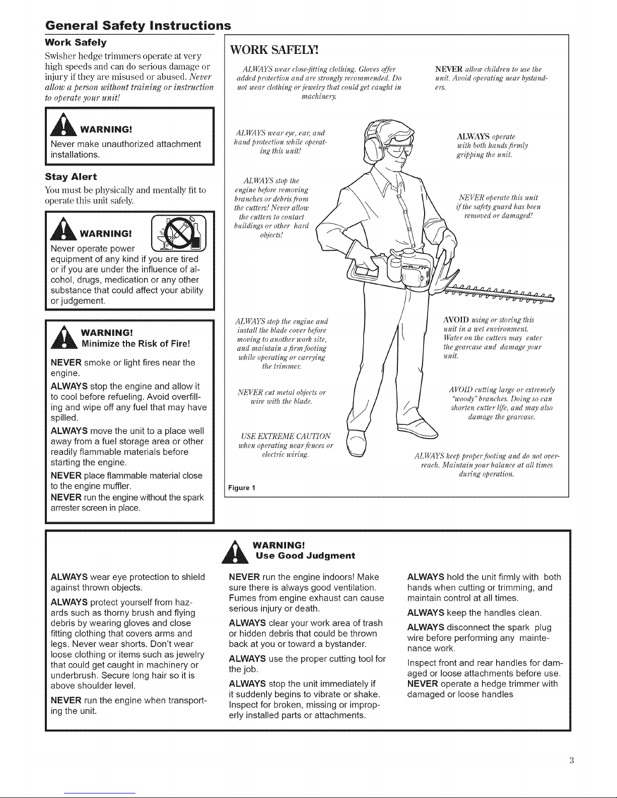
WORK SAFEL
ALWAYS wear close-fitting clothing. Gloves offer
added protection and am strongly recommended. Do
not wear clothing or jewehy that eould get caught in
machinery.
NEVER allow children to use the
unit. Avoid operating near bystand-
ers.
ALWAYS wear eye, eaJ, and
hand protection while operat-
ing this unit!
ALWAYS operate
with both hands firmly
gripping the uniL
ALWAYS stop the
engine b@re removing
branches or debris from
the cutters! Never allow
the cutters to contact
buildings or other hard
objects!
NEVER operate this unit
if the salty guard has been
removed or damaged!
ALWAYS stop the engine and
install the blade cover before
moving to another work site,
and maintain a firm footing
while operating or earJying
the trimmer.
NEVER cut metal objects or
wire with the blade.
USE EXTREME CA UTION
when operating near,rices or
electric wiring.
Figure I
AVOID using or storing this
unit in a wet environment.
Water on the cutters may enter
the gearcase and damage your
unit.
AVOID cutting large or extremely
"woody" branches. Doing so can
shorten cutter life, and may also
damage the gearcase.
ALWAYS ke@ p_vper footing and do not ove_
reach. Maintain your balance at all times
during operation.
ALWAYS wear eye protection to shield
against thrown objects.
ALWAYS protect yourself from haz-
ards such as thorny brush and flying
debris by wearing gloves and close
fitting clothing that covers arms and
legs. Never wear shorts. Don't wear
loose clothing or items such as jewelry
that could get caught in machinery or
underbrush. Secure long hair so it is
above shoulder level.
NEVER run the engine when transport-
ing the unit,
_ WARN|NG[
Use Good Judgment
NEVER run the engine indoors! Make
sure there is always good ventilation.
Fumes from engine exhaust can cause
serious injury or death.
ALWAYS clear your work area of trash
or hidden debris that could be thrown
back at you or toward a bystander.
ALWAYS use the proper cutting tool for
the job.
ALWAYS stop the unit immediately if
it suddenly begins to vibrate or shake.
Inspect for broken, missing or improp-
erly installed parts or attachments.
ALWAYS hold the unit firmly with both
hands when cutting or trimming, and
maintain control at all times.
ALWAYS keep the handles clean.
ALWAYS disconnect the spark plug
wire before performing any mainte-
nance work.
Inspect front and rear handles for dam-
aged or loose attachments before use.
NEVER operate a hedge trimmer with
damaged or loose handles
Page 4
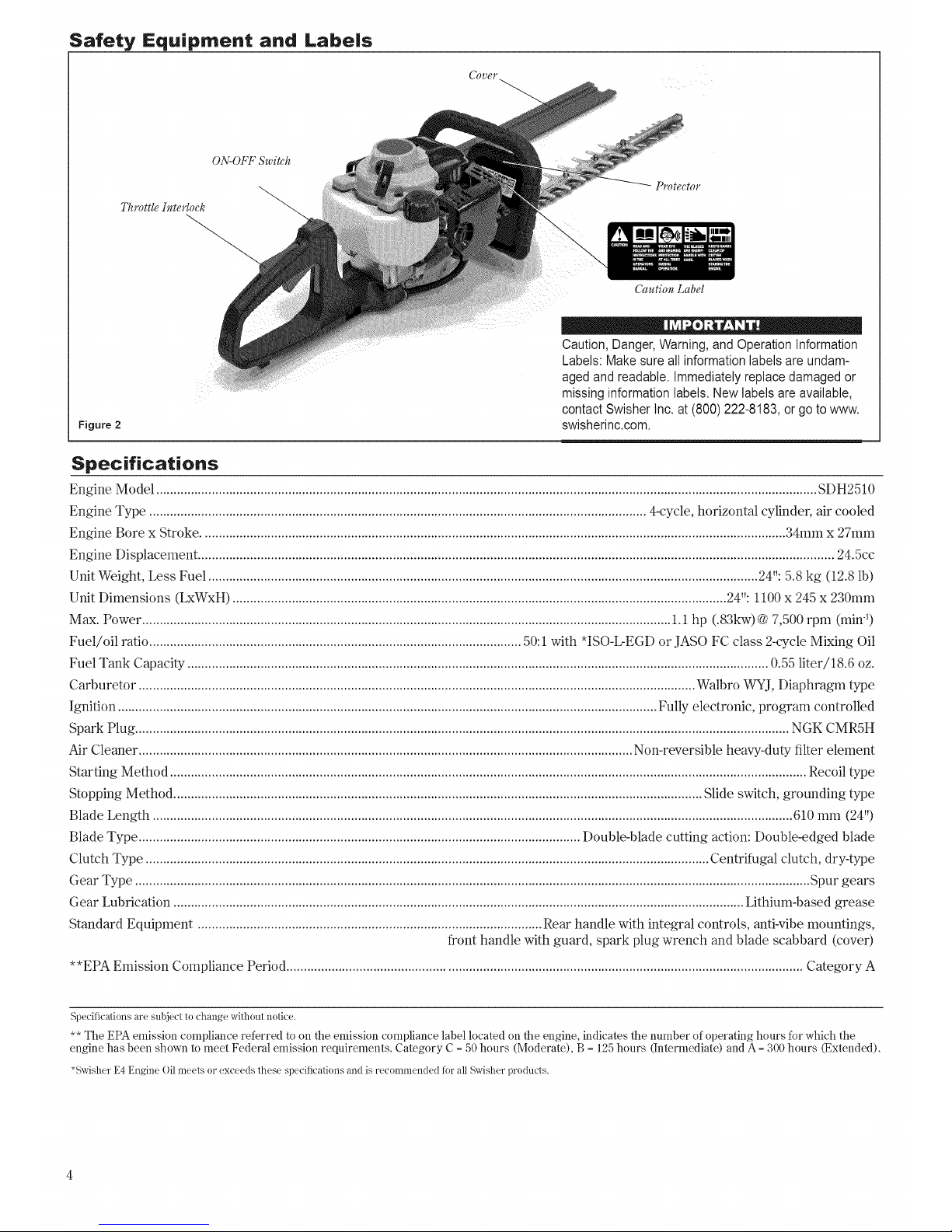
Safety Equipment and Labels
ON-OFF Switch
Throttle Interlock
Protector
Figure 2
Caution Label
• Q . ,
Caution,Danger,Warning,andOperationInformation
Labels:Makesureall informationlabelsare undam-
aged andreadable. Immediatelyreplacedamagedor
missinginformationlabels.Newlabelsareavailable,
contactSwisherInc. at (800)222-8183,or go to www.
swisherinc.com.
Specifications
Engine Model .............................................................................................................................................................................................. SDH2510
Engine Type ............................................................................................................................................... 4-cycle, horizontal cylinder, air cooled
Engine Bore x Stroke ........................................................................................................................................................................ 34mm x 27mm
Engine Displacement ....................................................................................................................................................................................... 24.5cc
Unit Weight, Less Fuel .............................................................................................................................................................. 24": 5.8 kg (12.8 lb)
Unit Dimensions (LxWxH) .............................................................................................................................................. 24": 1100 x 245 x 230mm
Max. Power ........................................................................................................................................................ 1.1 hp (.83kw)@ 7,500 rpm (min-1)
Fuel/oil ratio ........................................................................................................... 50:1with *ISO-L-EGD or JASO FC class 2-cycle Mixing Oil
Fuel Tank Capacity ....................................................................................................................................................................... 0.55 liter/18.6 oz.
Carburetor ................................................................................................................................................................ Walbro WYJ, Diaphragm type
Ignition ........................................................................................................................................................... Fully electronic, program controlled
Span Plug ............................................................................................................................................................................................ NGK CMR5H
Air Cleaner .............................................................................................................................................. Non-reversible heavy-duty filter element
Starting Method ....................................................................................................................................................................................... Recoil type
Stopping Method ........................................................................................................................................................ Slide switch, grounding type
Blade Length ........................................................................................................................................................................................ 610 mm (24")
Blade Type ............................................................................................................................... Double-blade cutting action: Double-edged blade
Clutch Type .................................................................................................................................................................. Centrifugal clutch, dry-type
Gear Type .................................................................................................................................................................................................. Spur gears
Gear Lubrication .................................................................................................................................................................... Lithium-based grease
Standard Equipment ................................................................................................... Rear handle with integral controls, anti-vibe mountings,
front handle with guard, spark plug wrench and blade scabbard (cover)
**EPA Emission Compliance Period .................................................................................................................................................... Category A
Specifications are subject to change without notice.
** The EPA emission compliance referred to on the emission compliance label located on tile engine, indicates tile number of operating hours for which the
engine has been shown to meet Federal emission requirements. Category C = 50 hours (Moderate), B = 125 hours (Intermediate) and A = 300 hours (Extended).
*Swisher E4 Engine Oillneets or exceeds these specifications and is recomrnended for all Swisher products.
Page 5
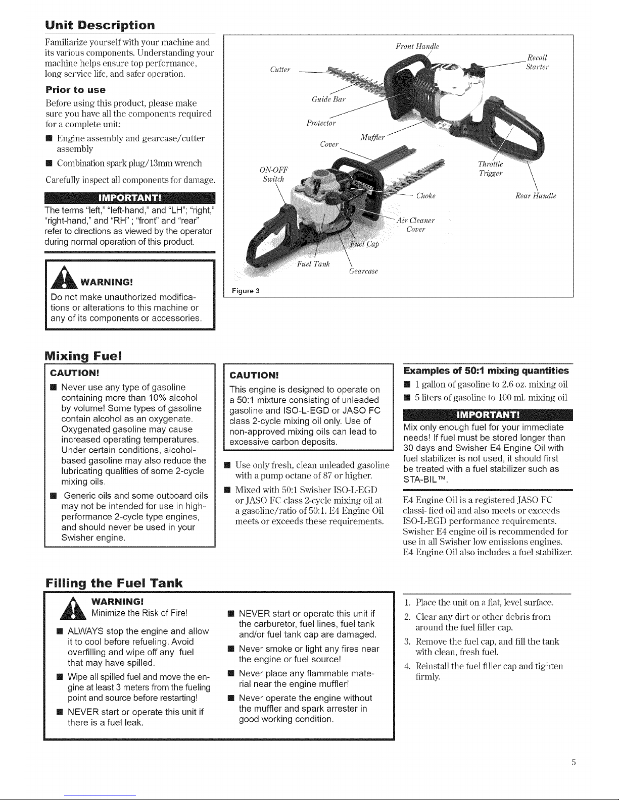
Unit Description
Familiarize yourself with your machine and
its various components. Understanding your
machine helps ensure top performance,
long service life, and safer operation.
Prior to use
Before using this product, please make
sure you have all the components required
Mr a complete unit:
[[ Engine assembly and gearcase/cutter
assembly
1[ Combination spark plug/13mm wrench
Carefully inspect all components for damage.
The terms "left," "left-hand," and "LH"; "right,"
"right-hand," and "RH" ; "front" and "rear"
refer to directions as viewed by the operator
during normal operation of this product.
_ WARNING!
Do not make unauthorized modifica-
tions or alterations to this machine or
any of its components or accessories,
Figure 3
Cutter
ON-OFF
Switch
\
Front Handle
/
Guide Bar
Protector
Cover
Choke
Cleaner
Cover
Throttle
Trigger
Fuel Tank
Gearease
Recoil
Starter
Rear Handle
Mixing Fuel
CAUTION!
m Never use any type of gasoline
containing more than 10% alcohol
by volume! Some types of gasoline
contain alcohol as an oxygenate.
Oxygenated gasoline may cause
increased operating temperatures.
Under certain conditions, alcohol-
based gasoline may also reduce the
lubricating qualities of some 2-cycle
mixing oils.
II Generic oils and some outboard oils
may not be intended for use in high-
performance 2-cycle type engines,
and should never be used in your
Swisher engine,
CAUTION[
This engine is designed to operate on
a 50:1 mixture consisting of unleaded
gasoline and ISO-L-EGD or JASO FC
class 2-cycle mixing oil only. Use of
non-approved mixing oils can lead to
excessive carbon deposits.
1[ Use only fresh, clean unleaded gasoline
with a pump octane of 87 or higher.
m Mixed with 50:1 Swisher ISO-L-EGD
or JASO FC class 2-cycle mixing oil at
a gasoline/ratio of 50:1. E4 Engine Oil
meets or exceeds these requirements.
Examples of 50:1 mixing quantities
II 1 gallon of gasoline to 2.6oz. mixing oil
!! 5 liters of gasoline to 100 mL mixing oil
Mix only enough fuel for your immediate
needsg If fuel must be stored longer than
30 days and Swisher E4 Engine Oil with
fuel stabilizer is not used, it should first
be treated with a fuel stabilizer such as
STA-BIL TM.
E4 Engine Oil is a registered JASO FC
classi- fled oil and also meets or exceeds
ISO-L-EGD performance requirements.
Swisher E4 engine oil is recommended for
use in all Swisher low emissions engines.
E4 Engine Oil also includes a fuel stabilizer.
Filling the Fuel Tank
i_k WARNING!Minimize the Risk of Fire!
m ALWAYS stop the engine and allow
it to cool before refueling. Avoid
overfilling and wipe off any fuel
that may have spilled.
m Wipe all spilled fuel and move the en-
gine at least 3 meters from the fueling
point and source before restarting!
m NEVER start or operate this unit if
there is a fuel leak.
II NEVER start or operate this unit if
the carburetor, fuel lines, fuel tank
and/or fuel tank cap are damaged,
II Never smoke or light any fires near
the engine or fuel sourceg
II Never place any flammable mate-
rial near the engine muffle!!
II Never operate the engine without
the muffler and spark arrester in
good working condition,
1. Place the unit on a fiat, level surface.
2. Clear any dirt or other debris from
around the fuel filler cap.
3. Remove the fuel cap, and fill the tank
with clean, fresh fuel.
4. Reinstall the fuel filler cap and tighten
firmly.
Page 6
Starting Procedure
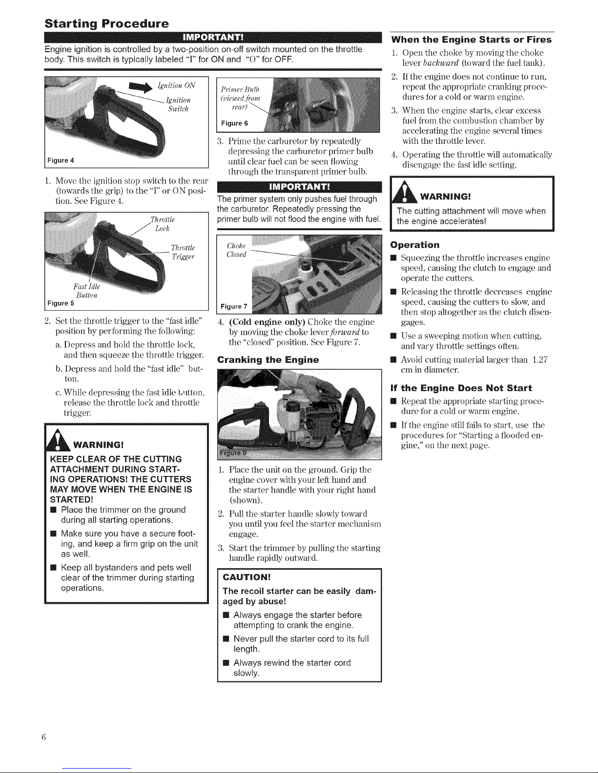
Engine ignition is controlled by a two-position on-off switch mounted on the throttle
body. This switch is typically labeled "F' for ON and "0" for OFF.
_ Iguitiou ON
Switch
Figure 4
1. Move the ignition stop switch to the rear
(towards the grip) to the 'T' or ON posi-
tion. See Figure 4.
Throttle
Lock
Throttle
Trigger
Fast Idle
Button
Figure 5
Primer Bulb
Figure 6
3. Prime the carburetor by repeatedly
depressing the carburetor primer bulb
until clear fuel can he seen flowing
through the transparent primer bulb.
The primersystem only pushes fuel through
the carburetor.Repeatedly pressing the
primer bulb will notflood the engine with fuel.
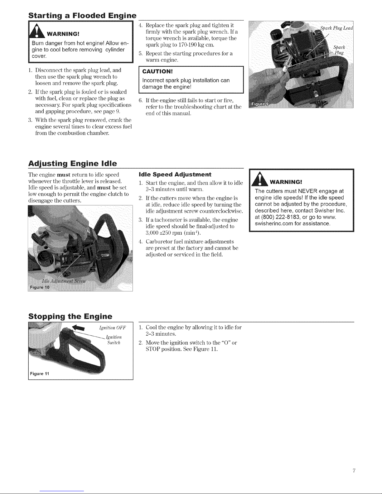
2. Set the throttle trigger to the "fast idle"
position by performing the following:
a. Depress and hold the throttle lock,
and then squeeze the throttle trigger.
b. Depress and hold the "fast idle" but-
ton.
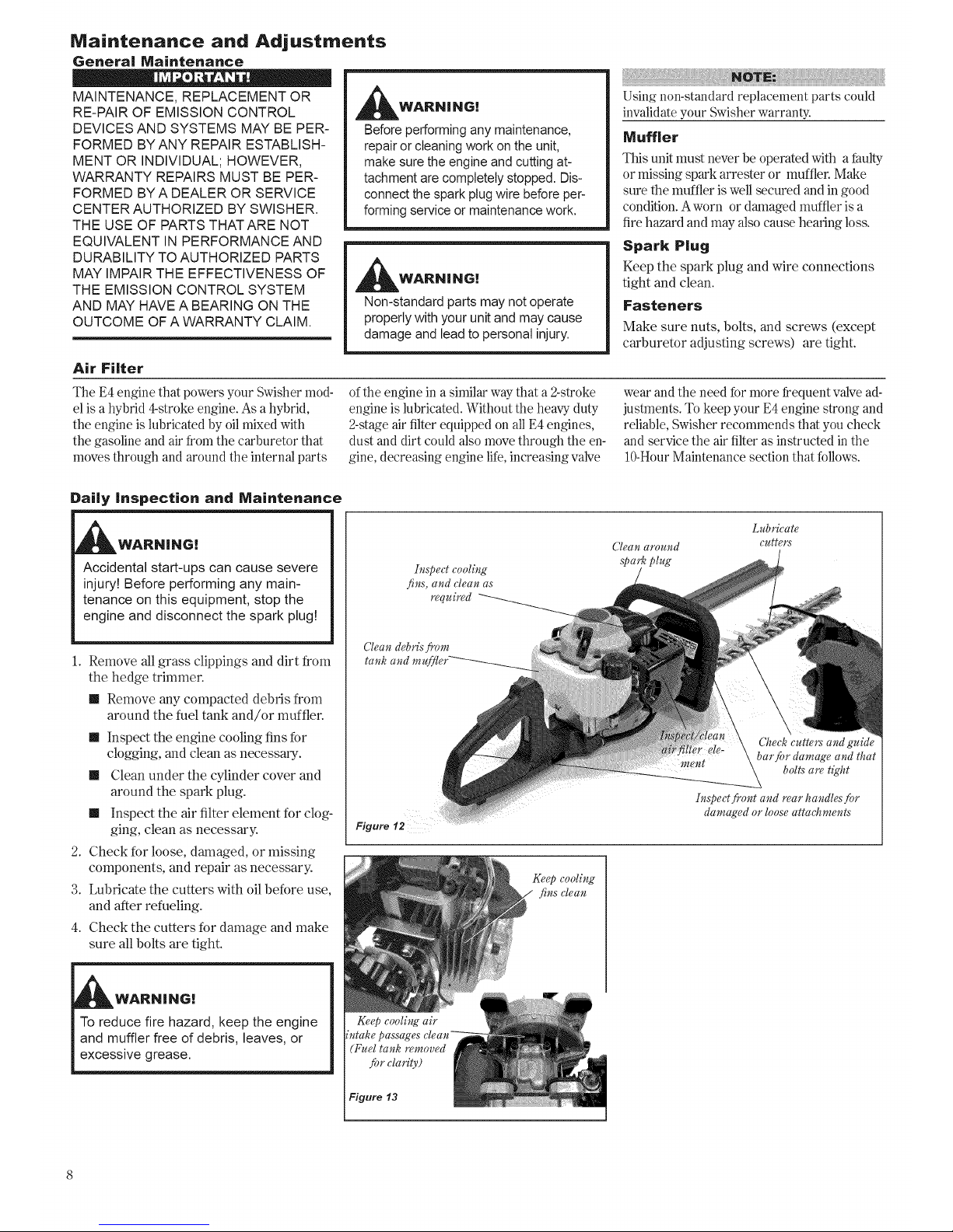
4. (Cold engine only) Choke the engine
by moving the choke lever forward to
the "closed" position. See Figure 7.
Cranking the Engine
c. While depressing the fast idle button ...............
release the throttle lock and throttle
trigger.
KEEP CLEAR OF THE CUTTING
ATTACHMENT DURING START=
ING OPERATIONS! THE CUTTERS
MAY MOVE WHEN THE ENGINE iS
STARTED)
m Place the trimmer on the ground
during all starting operations.
m Make sure you have a secure foot-
ing, and keep a firm grip on the unit
as well.
m Keep all bystanders and pets well
clear of the trimmer during starting
operations.
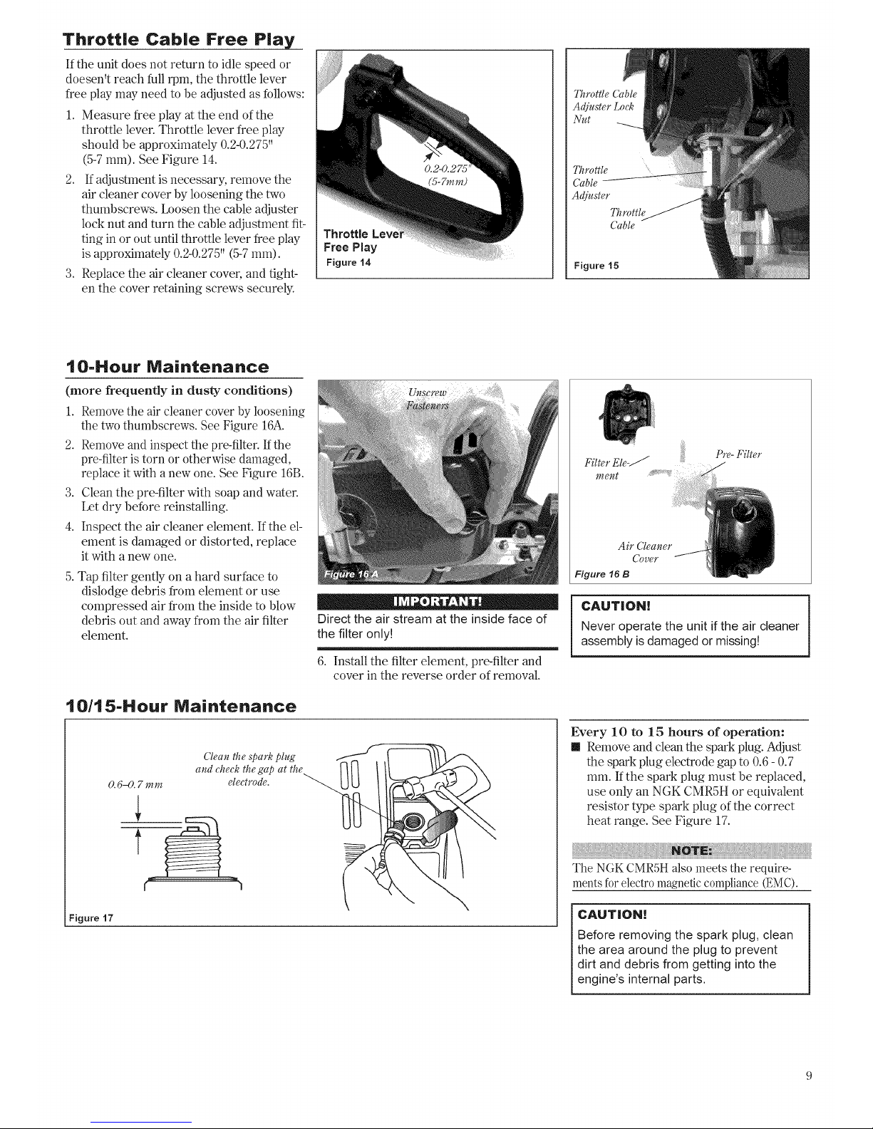
1. Place the unit on the ground. Grip the
engine cover with your left hand and
the starter handle with your right hand
(shown).
2. Pull the starter handle slowly toward
you until you feel the starter mechanism
engage.
3. Start the trimmer by pulling the starting
handle rapidly outward.
CAUTION!
The recoil starter can be easily dam-
aged by abuse[
m Always engage the starter before
attempting to crank the engine.
m Never pull the starter cord to its full
length.
m Always rewind the starter cord
slowly.
When the Engine Starts or Fires
1. Open the choke by moving the choke
lever backward (toward the fuel tank).
2. If the engine does not continue to run,
repeat the appropriate cranking proce-
dures for a cold or warm engine.
3. When the engine starts, clear excess
fuel from the combustion chamber by
accelerating the engine several times
with the throttle lever.
4. Operating the throttle will automatically
disengage the fast idle setting.
WARN|NG[
Operation
m Squeezing the throttle increases engine
speed, causing the clutch to engage and
operate the cutters.
m Releasing the throttle decreases engine
speed, causing the cutters to slow, and
then stop altogether as the clutch disen-
gages.
m Use a sweeping motion when cutting,
and vary throttle settings often.
m Avoid cutting material larger than 1.27
cm in diameter.
if the Engine Does Not Start
m Repeat the appropriate starting proce-
dure for a cold or warm engine.
m If the engine still fails to start, use the
procedures for "Starting a flooded en-
gine," on the next page.
Page 7
Starting a Flooded Engine
WARN|NG!
Burn danger from hot engine! Allow en-
gine to cool before removing cylinder
cover.
1. Disconnect the spark plug lead, and
then use the spark plug wrench to
loosen and remove the spark plug.
2. If the spark plug is fouled or is soaked
with fuel, clean or replace the plug as
necessary. For spark plug specifcations
and gapping procedure, see page 9.
3. With the spark plug removed, crank the
engine several times to clear excess fuel
from the combustion chamber.
4. Replace the spark plug and tighten it
firmly with the spark plug wrench. If a
torque wrench is available, torque the
spark plug to 170-190 kg cm.
5. Repeat the starting procedures for a
warm engine.
CAUTION
Incorrect spark plug installation can
damage the engine!
6. If the engine still fails to start or fire,
refer to the Foubleshooting chart at the
end of this manual.
Adjusting Engine idle
The engine must return to idle speed
whenever the throttle lever is released.
Idle speed is adjustable, and must be set
low enough to permit the engine clutch to
disengage the cutters.
|d|e Speed Adjustment
1. Start the engine, and then allow it to idle
2-3 minutes until warm.
2. If the cutters move when the engine is
at idle, reduce idle speed by turning the
idle adjustment screw counterclockwise.
3. If a tachometer is available, the engine
idle speed should be final-adjusted to
3,000 _+250rpm (rain-l).
4. Carburetor fuel mixture adjustments
are preset at the factory and cannot be
adjusted or serviced in the field.
_ WARN|N6!
The cutters must NEVER engage at
engine idle speeds! Ifthe idle speed
cannot be adjusted by the procedure,
described here, contact Swisher Inc.
at (800) 222-8183, or go to www.
swisherinc.com for assistance.
Figure 11
1.
2.
Cool the engine by allowing it to idle for
2-3 minutes.
Move the ignition switch to the "O" or
STOP position. See Figure 11.
Page 8
Maintenance and Adjustments
General Maintenance
MAINTENANCE, REPLACEMENT OR
RE-PAIR OF EMISSION CONTROL
DEVICES AND SYSTEMS MAY BE PER-
FORMED BY ANY REPAIR ESTABLISH-
MENT OR INDIVIDUAL; HOWEVER,
WARRANTY REPAIRS MUST BE PER-
FORMED BYA DEALER OR SERVICE
CENTER AUTHORIZED BY SWISHER.
THE USE OF PARTS THATARE NOT
EQUIVALENT IN PERFORMANCE AND
DURABILITY TO AUTHORIZED PARTS
MAY IMPAIR THE EFFECTIVENESS OF
THE EMISSION CONTROL SYSTEM
AND MAY HAVE A BEARING ON THE
OUTCOME OFA WARRANTY CLAIM.
WARNING[
Beforeperformingany maintenance,
repairor cleaningwork on the unit,
make surethe engineandcuttingat-
tachmentare completelystopped. Dis-
connectthespark plug wire beforeper-
formingserviceor maintenancework.
_likWARi\l i i\lG!
Non-standard parts may not operate
properly with your unit and may cause
damage and lead to personal injury.
Using non-standard replacement parts could
invalidate your Swisher warranty.
Muffler
This unit must never be operated with a faulty
or missing spark arrester or muffler. Make
sure the muffler is well secured and in good
condition. Aworn or damaged muffler is a
fire hazard and may also cause hearing loss.
Spark Plug
Keep the spark plug and wire connections
tight and clean.
Fasteners
Make sure nuts, bolts, and screws (except
carburetor adjusting screws) are tight.
Air Filter
The E4 engine that powers your Swisher mod-
el is a hybrid 4-stroke engine. As a hybrid,
the engine is lubricated by oil mixed with
the gasoline and air from the carburetor that
moves through and around the internal parts
of the engine in a similar way that a 2-stroke
engine is lubricated. Without the heavy duty
2-stage air filter equipped on all E4 engines,
dust and dirt could also move through the en-
gine, decreasing engine life, increasing valve
wear and the need for more frequent valve ad-
justments. To keep your E4 engine strong and
reliable, Swisher recommends that you check
and service the air flter as instructed in the
10-HourMaintenance section that follows.
Daily Inspection and Maintenance
_WARN|NG!
Accidental start-ups can cause severe
injury! Before performing any main-
tenance on this equipment, stop the
engine and disconnect the spark plug!
1. Remove all grass clippings and dirt from
the hedge trimmer.
m Remove any compacted debris from
around the fuel tank and/or muffler.
m Inspect the engine cooling fins for
clogging, and clean as necessary.
m Clean under the cylinder cover and
around the spark plug.
m Inspect the air filter element for clog-
ging, clean as necessary.
2. Check for loose, damaged, or missing
components, and repair as necessary.
3. Lubricate the cutters with oil before use,
and after refueling.
4. Check the cutters for damage and make
sure all bolts are tight.
WARNING!
Iuspect cooling
fins, and clean as
required
Cleau aYouud
spark plug
Clean debrisfrom
tank and mu
Figure 12
bolts are tight
Iuspect fivut and rear handles for
damaged or loose attaehments
Ke@ cooling air
intake passages
_Fuel tank removed
fi) r elarity)
Figure 13
Page 9
Throttle Cab|e Free P|ay
If the unit does not return to idle speed or
doesen_t reach full rpm, the throttle lever
free play may need to be adjusted as follows:
1. Measure free play at the end of the
throttle lever. Throttle lever free play
should be approximately 0.2-0.275"
(5-7 mm). See Figure 14.
2. If adjustment is necessary, remove the
air cleaner cover by loosening the two
thumbscrews. Loosen the cable adjuster
lock nut and turn the cable adjustment fit-
ting in or out until throttle lever free play
is approximately 0.2-0.275" (5-7 mm).
3. Replace the air cleaner cover, and tight-
en the cover retaining screws securely.
Throttle
Free Play
Figure 14
Throttle
Cable
I O-Hour Maintenance
(more frequently in dusty conditions)
1. Remove the air cleaner cover by loosening
the two thumbscrews. See Figure 16A.
2. Remove and inspect the pre-filter. If the
pre-filter is torn or otherwise damaged,
replace it with a new one. See Figure 16B.
3. Clean the pre-filter with soap and water.
Let dry before reinstalling.
4. Inspect the air cleaner element. If the el-
ement is damaged or distorted, replace
it with a new one.
5. Tap filter gently on a hard surface to
dislodge debris from element or use
compressed air from the inside to blow
debris out and away from the air filter
element.
10/15-Hour Maintenance
Direct the air stream at the inside face of
the filter only!
6. Install the filter element, pre-filter and
cover in the reverse order of removal.
O.6-0. 7 mm
Clean the spark plug
and check the gap at the
electrode.
f
Figure 17
Pre- Filter
Filter Ele-J
Air Cleaner
Cover
Figure 16 B
CAUTION!
Never operate the unit if the air cleaner
assembly is damaged or missing!
Every 10 to 15 hours of operation:
m Remove and clean the spark plug. Adjust
the spark plug electrode gap to 0.6 - 0.7
mm. If the spark plug must be replaced,
use only an NGK CMR5H or equivalent
resistor type spark plug ofthe correct
heat range. See Figure 17.
The NGK CMR5H also meets the require-
ments for electro magnetic compliance (EMC).
CAUTION!
Before removing the spark plug, clean
the area around the plug to prevent
dirt and debris from getting into the
engine's internal parts.
Page 10
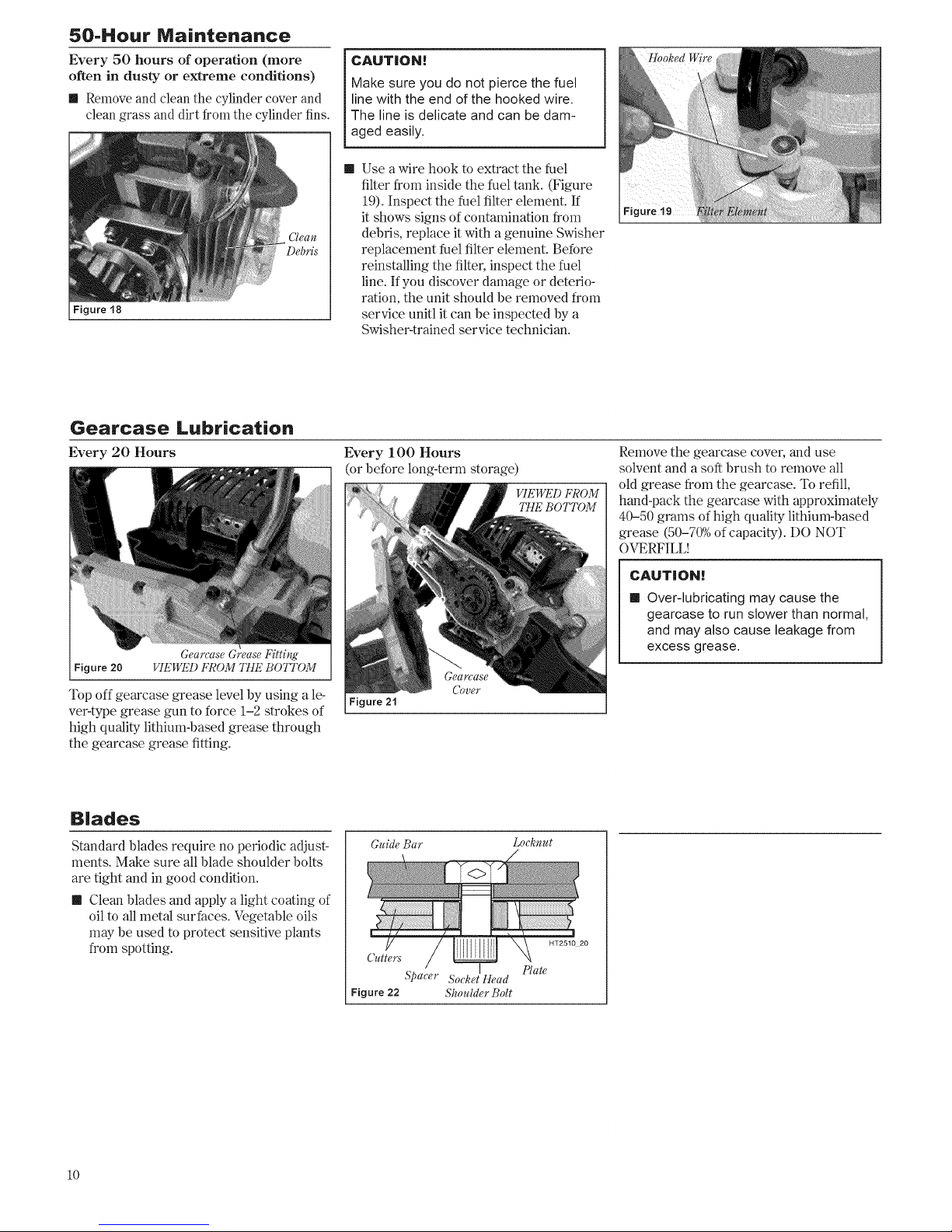
50-Hour Maintenance
Every 50 hours of operation (more
often in dusty or extreme conditions)
Remove and clean the cylinder cover and
clean grass and dirt from the cylinder fins.
Debris
Figure 18
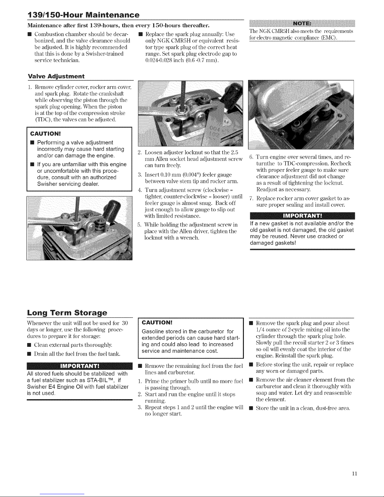
CAUTION[
Make sure you do not pierce the fuel
line with the end of the hooked wire.
The line is delicate and can be dam-
aged easily.
II Use a wire hook to extract the fuel
filter from inside the fuel tank. (Figure
19). Inspect the fuel filter element. If
it shows signs of contamination from
debris, replace it with a genuine Swisher
replacement fuel filter element. Before
reinstalling the filter, inspect the fuel
line. If you discover damage or deterio-
ration, the unit should be removed from
service unitl it can be inspected by a
Swisher-trained service technician.
Gearcase Lubrication
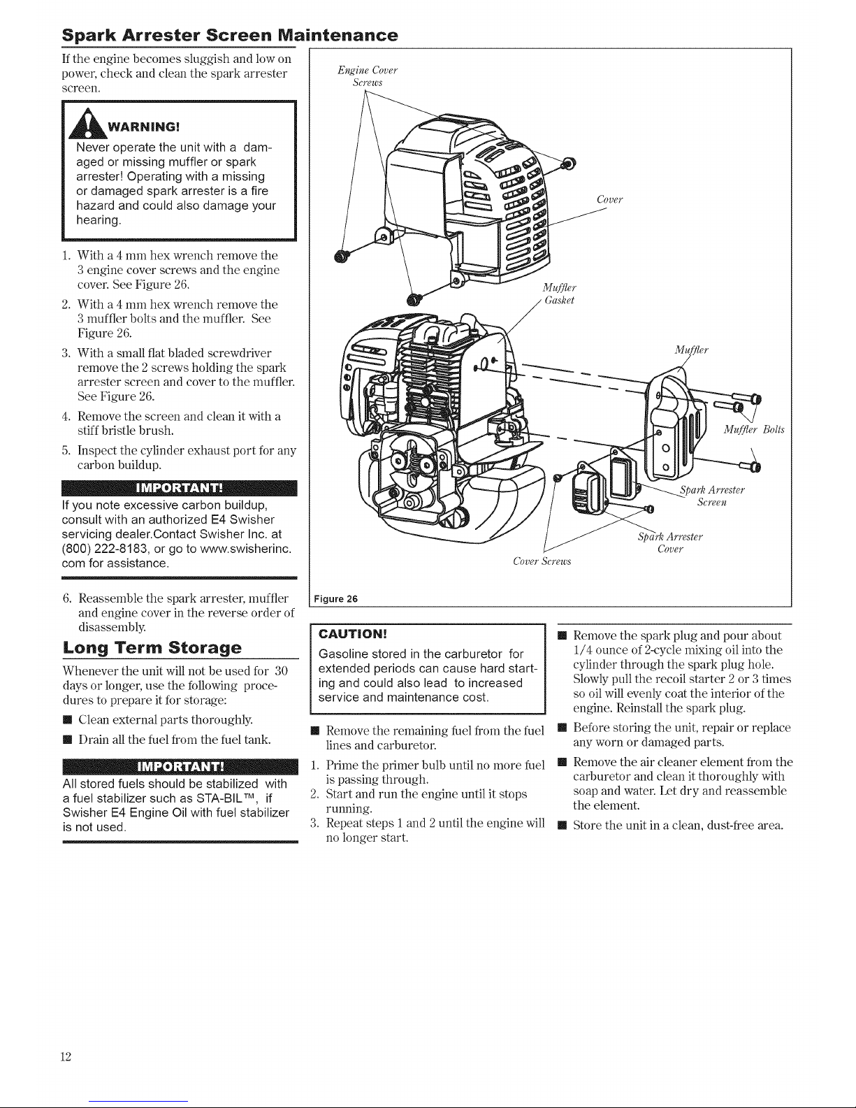
Every 20 Hours
Figure 20
Gearcase Grease Fitting
VIEWED FROM THE BOTTOM
Top off gearcase grease level by using a le-
ver-type grease gun to force 1-2 strokes of
high quality lithium-based grease through
the gearcase grease fitting.
Every 100 Hours
(or before long-term storage)
VIEWED FROM
THE BOTTOM
Figure 21
Gearcase
Cover
Remove the gearcase cover, and use
solvent and a soft brush to remove all
old grease from the gearcase. To refill,
hand-pack the gearcase with approximately
40-50 grams of high quality lithium-based
grease (50-70% of capacity). DO NOT
OVERFILL!
CAUTION[
II Over-lubricating may cause the
gearcase to run slower than normal,
and may also cause leakage from
excess grease.
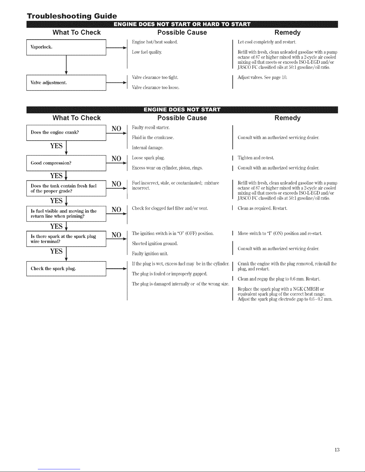
Blades
Standard blades require no periodic adjust-
ments. Make sure all blade shoulder bolts
are tight and in good condition.
m Clean blades and apply a light coating of
oil to all metal surfaces. Vegetable oils
may be used to protect sensitive plants
from spotting.
Guide Bar
Locknut
Cutters
Spacer Socket Head
Figure 22 Shoulder Bolt
Plate
10
Page 11
139/150-Hour Maintenance
Maintenance after first 139-hours, then every 150-hours thereafter.
m Combustion chamber should be decar- m Replace the spark plug annually: Use
bonized, and the valve clearance should only NGK CMR5H or equivalent resis-
be adjusted. It is highly recommended tor type spark plug of the correct heat
that this is done by a Swisher-trained range. Set spark plug electrode gap m
service technician. 0.024-0.028 inch (0.6 -0.7 mm).
The NGK CMRSH also meets the requirements
for electro magnetic compliance _MC).
Valve Adjustment
1. Remove cylinder cover, rocker arm cover,
and spark plug. Rotate the crankshaft
while observing the piston through the
spark plug opening. When the piston
is at the top of the compression stroke
(TDC), the valves can be adjusted.
CAUT|ON!
II Performing a valve adjustment
incorrectly may cause hard starting
and/or can damage the engine.
II If you are unfamiliar with this engine
or uncomfortable with this proce-
dure, consult with an authorized
Swisher servicing dealer.
2. L_)osen adjuster locknut so that the 2.5
mm Allen socket head adjustment screw
can turn freely.
3. Insert 0.10 mm (0.004") feeler gauge
between valve stem tip and rocker arm.
4. Turn adjustment screw (clockwise =
tighter, counter-clockwise = looser) until
feeler gauge is almost snug. Back off
just enough to allow gauge to slip out
with limited resistance.
5.
While holding the adjustment screw in
place with the Allen driver, tighten the
locknut with a wrench.
6. Turn engine over several times, and re-
turnthe to TDC-compression. Recheck
with proper feeler gauge to make sure
clearance adjustment did not change
as a result of tightening the locknut.
Readjust as necessary.
7. Replace rocker arm cover gasket to as-
sure proper sealing and install cover.
If a new gasket is not available and/or the
old gasket is not damaged, the old gasket
may be reused. Never use cracked or
damaged gaskets!
Long Term Storage
Whenever the unit will not be used for 30
days or longer, use the following proce-
dures to prepare it for storage:
1[ Clean external parts thoroughly.
1[ Drain all the fuel from the fuel tank.
All stored fuels should be stabilized with
a fuel stabilizer such as STA-BIL TM, if
Swisher E4 Engine Oil with fuel stabilizer
is not used.
CAUT|ON!
Gasoline stored in the carburetor for
extended periods can cause hard start-
ing and could also lead to increased
service and maintenance cost.
1[ Remove the remaining fuel from the fuel
lines and carburetor.
1. Prime the primer bulb until no more fuel
is passing through.
2. Start and run the engine until it stops
running.
3. Repeat steps 1 and 2 until the engine will
no longer start.
1[ Remove the spark plug and pour about
1/4 ounce of 2-cycle mixing oil into the
cylinder through the spark plug hole.
Slowly pull the recoil starter 2 or 3 times
so oil will evenly coat the interior of the
engine. Reinstall the spark plug.
1[ Before storing the unit, repair or replace
any worn or damaged parts.
1[ Remove the air cleaner element from the
carburetor and clean it thoroughly with
soap and water. Let dry and reassemble
the element.
11 Store the unit in a clean, dust-free area.
11
Page 12
Spark Arrester Screen
If the engine becomes sluggish and low on
power, check and clean the spark arrester
screen.
_1 WARNING!
Never operate the unit with a dam-
aged or missing muffler or spark
arrested Operating with a missing
or damaged spark arrester is a fire
hazard and could also damage your
hearing,
1. With a 4 mm hex wrench remove the
3 engine cover screws and the engine
cover. See Figure 26.
2. With a 4 mm hex wrench remove the
3 muffler bolts and the muffler. See
Figure 26.
3. With a small flat bladed screwdriver
remove the 2 screws holding the spark
arrester screen and cover to the muffler.
See Figure 26.
4. Remove the screen and clean it with a
stiff bristle brush.
5. Inspect the cylinder exhaust port for any
carbon buildup.
If you note excessive carbon buildup,
consult with an authorized E4 Swisher
servicing dealer.Contact Swisher Inc. at
(800) 222-8183, or go to www.swisherinc.
corn for assistance.
6. Reassemble the spark arrester, muffler
and engine cover in the reverse order of
disassembly.
Long Term Storage
Whenever the unit will not be used for 30
days or longer, use the following proce-
dures to prepare it for storage:
II Clean external parts thoroughly.
II Drain all the fuel from the fuel tank.
Maintenance
Engine Cover
Screws
All stored fuels should be stabilized with
a fuel stabilizer such as STA-BIL TM, if
Swisher E4 Engine Oil with fuel stabilizer
is not used.
Muffler
Gasket
Cover Screws
Figure 26
CAUTION!
Gasoline stored in the carburetor for
extended periods can cause hard start-
ing and could also lead to increased
service and maintenance cost.
II Remove the remaining fuel from the fuel
lines and carburetoc
1. Prime the primer bulb until no more fuel
is passing through.
2. Start and run the engine until it stops
running.
3. Repeat steps i and 2 until the engine will
no longer start.
(]ouey
Muffler Bolts
Spark Arrester
Screen
Spark Arrester
Cover
II Remove the spark plug and pour about
1/4 ounce of 2-cycle mixing oil into the
cylinder through the spark plug hole.
Slowly pull the recoil starter 2 or 3 times
so oil will evenly coat the interior of the
engine. Reinstall the spark plug.
II Before storing the unit, repair or replace
any worn or damaged parts.
II Remove the air cleaner element from the
carburetor and clean it thoroughly with
soap and water. Let dry and reassemble
the element.
II Store the unit in a clean, dust-free area.
12
Page 13
Troubleshooting Guide
What To Check Possible Cause Remedy
Vaporlock.
1
Valve adjustment.
Engine hot/heat soaked.
Lowfuel quality.
Valveclearance too tight.
Valveclearance too loose.
Let cool completely and restart.
Refill with fresh, clean unleaded gasoline with a pump
octane of87 or higher mixed with a 2-cycle air cooled
mixing oil that meets or exceeds ISO-L-EGDand/or
JASCOFC classified oils at 50:1gasoline/oil ratio.
Adjust valves. See page 10.
What To Check Possible Cause Remedy
Does the engine crank?
YEs
Good compression?
YEs
Does the tank contain fresh fuel
of the proper grade?
YEs
Is fuel visible and moving in the
return line when priming?
YEs
Is there spark at the spark plug
wire terminal?
Check the spark plug.
Faulty recoil starter.
Fluid in the crankcase.
Internal damage.
Loosespark plug.
Excess wear on cylinder, piston, rings.
Fuel incorrect, stale, or contaminated; mixture
incorrect.
Check for clogged fuel filter and/or vent.
The ignition switch is in "O" (OFF) position.
Shorted ignition ground.
Faulty ignition unit.
Ifthe plug is wet, excess fuel may be in the cylinder.
The plug is fouled or improperly gapped.
The plug is damaged internally or ofthe wrong size.
Consult with an authorized servicing dealer.
I Tighten and re-test.
I Consult with an authorized servicing dealer.
Refill with fresh, clean unleaded gasoline with a pump
octane of87 or higher mixed with a 2-cycle air cooled
mixing oil that meets or exceeds ISO-L-EGDand/or
JASCOFC classified oils at 50:1gasoline/oil ratio.
Clean as required. Restart.
Move switch to "I" (ON) position and re-start.
Consult with an authorized servicing dealer.
Crank the engine with the plug removed, reinstall the
plug, and restart.
Clean and regap the plug to 0.6mm. Restart.
Replace the spark plug with a NGKCMR5H or
equivalent spark plug of the correct heat range.
Adjust the spark plug electrode gap to 0.6- 0.7 ram.
13
Page 14
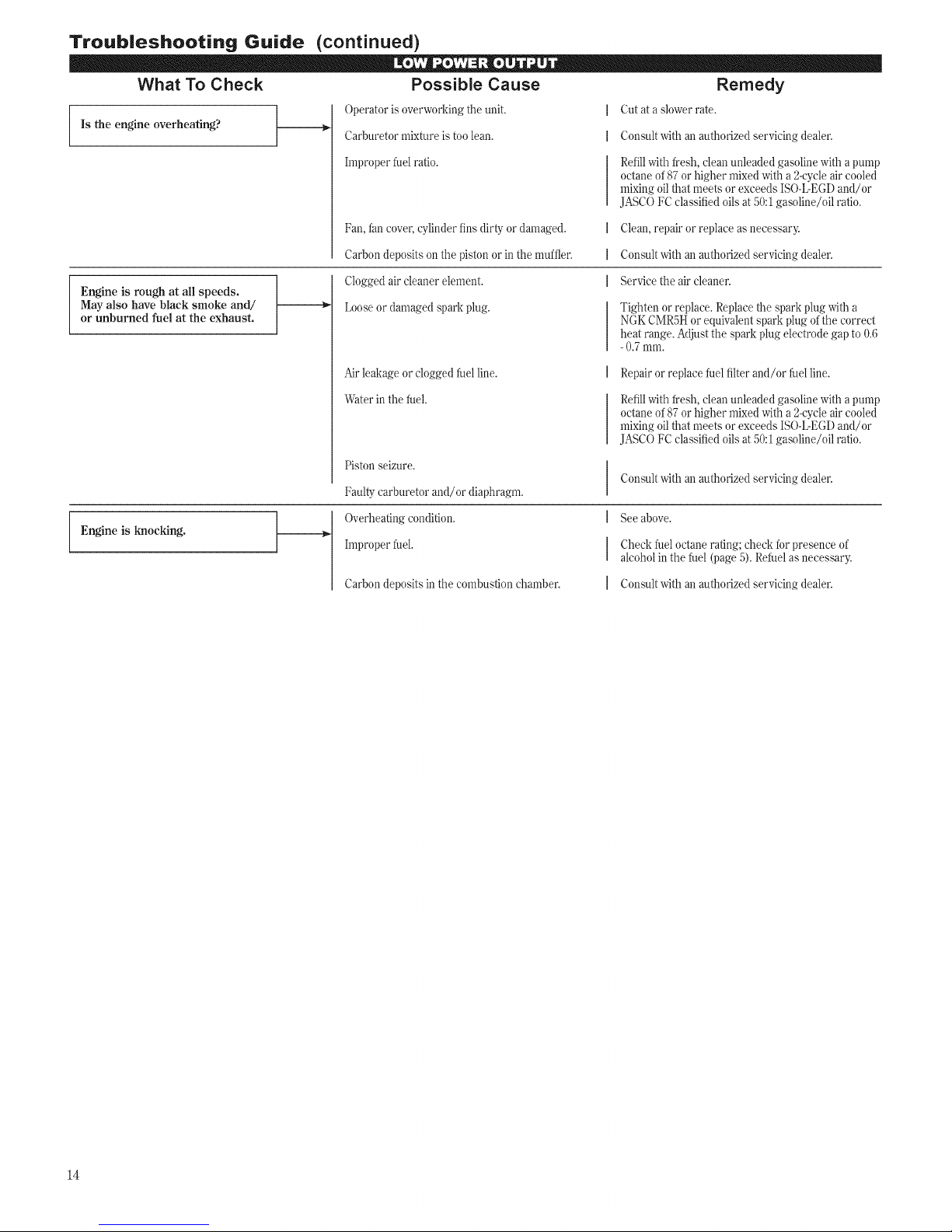
Troubleshooting Guide (continued)
Possible Cause
Operator is overworking the unit.
Carburetor mixture is too lean,
Improper fuel ratio.
What To Check
Is the engine overheating?
Fan, fan cover, cylinder fins dirty or damaged.
Carbon deposits on the piston or in the mufflen
Clogged air cleaner element.
Loose or damaged spark plug.
Engine is rough at all speeds.
May also have black smoke and/
or unburned fuel at the exhaust.
Air leakage or clogged fuel line.
Water in the fuel.
Piston seizure.
Remedy
Cut at a slower rate.
Consult with an authorized servicing dealer.
Refill with fresh, clean unleaded gasoline with a pump
octane of 87 or higher mixed with a 2-cycle air cooled
mixing oil that meets or exceeds ISO-L-EGD and/or
JASCO FC classified oils at 50:1 gasoline/oil ratio.
Clean, repair or replace as necessary.
Consult with an authorized servicing dealer.
Service the air cleaner.
Tighten or replace. Replace the spark plug with a
NGK CMR5H or equivalent spark plug of the correct
heat range. Adjust the spark plug electrode gap to 0.6
-0.7 mm.
Repair or replace fuel filter and/or fuel line.
Refill with fresh, clean unleaded gasoline with a pump
octane of87 or higher mixed with a 2-cycleair cooled
mixing oil that meets or exceeds ISO-L-EGDand/or
JASCOFC classified oils at 50:1gasoline/oil ratio.
Engine is knocking.
Faulty carburetor and/or diaphragm.
Overheating condition.
Improper fuel.
Carbon deposits in the combustion chamber.
Consult with an authorized servicing dealer.
See above.
Check fuel octane rating; check for presence of
alcohol in the fuel (page 5). Refuel as necessarg
Consult with an authorized servicing dealer.
14
Page 15
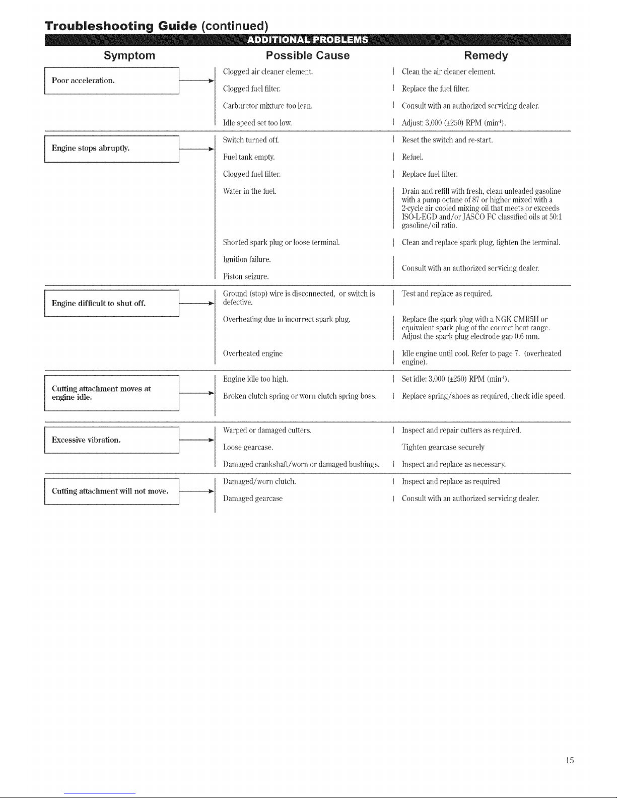
Troubleshooting Guide (continued)
Symptom Possible Cause Remedy
Clogged air cleaner element. Clean the air cleaner element.
Poor acceleration.
Engine stops abruptly.
Engine difficult to shut off.
Clogged fuel filter.
Carburetor mixture too lean.
Idle speed set too low.
Switchturned off.
Fuel tank empty.
Clogged fuel filter.
Water in the fuel.
Cutting attachment moves at
engine idle.
Replacethe fuel filter.
Consult with an authorized servicing dealer.
Adjust:3,000 (_+250)RPM (min%
Reset the switch and re-start.
Refuel.
Replacefuel filter.
[)rain and refill with fresh, clean unleaded gasoline
with a pump octane of 87 or higher mixed with a
2-cycleair cooled mixing oilthat meets or exceeds
ISO-L-EGDand/or JASCO FCclassified oils at 50:1
gasoline/oil ratio.
Shorted spark plug or loose terminal.
Ignition failure.
Piston seizure.
Ground (stop) wire is disconnected, or switch is
defective.
Overheating due to incorrect spark plug.
Overheated engine
Engine idle too high.
Broken clutch spring or worn clutch spring boss.
Clean and replace spark plug, tighten the terminal.
Consult with an authorized servicing dealer.
Test and replace as required.
Replacethe spark plug with a NGK CMR5Hor
equivalent spark plug of the correct heat range.
Adjust the spark plug electrode gap 0.6 mm.
Idle engine until cool. Refer to page 7. (overheated
engine).
Set idle: 3,000 (_+250)RPM (min%
Replace spring/shoes as required, check idle speed.
Excessive vibration.
Cutting attachment will not move.
Warped or damaged cutters.
L_osegearcase.
Damaged crankshaft/worn or damaged bushings.
Damaged/worn clutch.
Damaged gearcase
Inspect and repair cutters as required.
Tighten gearcase securely
Inspect and replace as necessary.
Inspect and replace as required
Consult with an authorized servicing dealer.
15
Page 16

Emission System Warranty Statement (Administered by Shindaiwa inc.)
Your Warranty Rights and
Obligations
The California Air Resources Board, the U.S. Environmental
Protection Agency and Shindaiwa Corporation are pleased to
explain the exhaust and evaporative emission control system
warranty on your new small off-road (non-road) engine.
In California, new small off-road engines must be designed,
built, and equipped to meet the State's stringent anti-smog stan-
dards. In other states, new 1997 and later non-road engines must
meet the Federal EPA's stringent anti-smog standards.
Shindaiwa Corporation must warrant the emission control sys-
tem on your small off-road engine for the periods of time listed
below, provided there has been no abuse, neglect, or improper
maintenance of your small off-road engine.
Your engine exhaust and evaporative emission control system
includes parts such as the carburetol; fuel tank, the ignition sys-
tem and, if equipped, the catalytic converter. These components
are specifically listed below.
Where a warrantable condition exists, Shindaiwa Corporation
will repair your small off-road engine at no cost to you including
diagnosis, parts, and labol:
Manufacturer's Warranty
Coverage
When sold within the U.S., this engine's emission control
system is warranted for a period of two (2) years from the date
this product is first delivered to the original retail purchaser.
During the warranty period, Shindaiwa Corporation will, at
their option, repair or replace any defective emission-related
component on this engine. During the original Warranty Period,
these Warranty Rights are automatically transferable to subse-
quent owners of this product.
What is Covered by this
Warranty
1. Carburetor Internal Components
m Throttle Valve, Needle, Jet, Metering Diaphragm
2. Fuel Tank
3. Ignition System Components
m Ignition Coil
m Flywheel Rotor
4. Catalytic Converter (if originally equipped)
The emission control system for your particular Shindaiwa
engine may also include certain related hoses and connectors.
Owners Warranty
Responsibilities
As the small off-road engine owner, you are responsible for
the performance of the required maintenance listed in this own-
ers manual. Shindaiwa Corporation recommends that you retain
all receipts covering maintenance on your small off-road engine,
but Shindaiwa Corporation cannot deny warranty solely for the
lack of receipts or for your failure to ensure the performance of
all scheduled maintenance.
As the small off-road engine owner, you should be aware,
however, that Shindaiwa Corporation may deny you warranty
coverage if your small off-road engine or a part has failed due to
abuse, neglect, improper maintenance, or unapproved modifica-
tions.
You are responsible for presenting your small off-road engine
to an authorized Shindaiwa Dealer as soon as a problem ex-
ists. The warranty repairs should be completed in a reasonable
amount of time, not to exceed 30 days.
If you have any questions regarding your warranty rights
and responsibilities, you should contact a Shindaiwa customer
service representative at (503) 692-3070 or your local Shindaiwa
Dealer.
Consequential Damages
In the event that other component parts of this product are
damaged by the failure of a warranted part, Shindaiwa Corpora-
tion will repair or replace such component parts at no charge to
you.
What is Not Covered
m Failures caused by abuse, neglect, or improper
maintenance procedures.
II Failures caused by the use of modified or non-approved parts
or attachments.
This Warranty is Administered by:
Shindaiwa Inc.
11975 S.W. Herman Rd.
Tualatin, OR 97062
(503) 692-3070
Swisher
EO. Box 67
Warrensburg, MO 64093
Part Number 81953
Revision 12/2007
16
Page 17

SWISHER MANUAL DEL PROPiETAR|O/OPERADOR
CORTADORA DE SETOS E4-
F4-HT3000
iADVERTENC|A!
Minimize el riesgo de accidentes contra usted u otras personas. Lea
este manual y familiaricese con sus contenidos. Siempre utilice pro-
tecci6n para los ojos y oidos cuando la maquina sea usada.
Ndlnero de Parte 81955 Revisado 10/07
Page 18

introducci6n
La cortadora de setos Swisher Sefie E4-
HT3000 ha sido disefiada y construida para
suministrar rendimiento superior y seguri-
dad sin comprometer calidad, comodidad o
durabilidad.
Los motores de alto rendimiento Swisher
representan la tecnologia lider en momres
de enfriados por aire, de cilindrada y peso
notablemente bajos que desarrollan suma
)otencia. Como duefio/operafio, usted muy
)ronto descubfirfi pot que Swisher, simple-
nente, es la unica en su clase.
!La informaci6n contenida en este manual
describe las maquinas disponibles en el
momento de publicacidn! Aunque todo es-
fuerzo sea hecho para proveerle la mas
reciente informaci6n sobre su producto
Swisher, podria haber algunas diferencias
entre su cortadora de setos E4-HT3000 y
las descritas en este manual.
Swisher se reserva el derecho de hacer cam-
bios a sus productos sin notificaci6n previa y
sin obligaci6n alguna de hacer alteraciones a
maquinas previamente fabricadas.
_I_IADVERTENC|A!
Las emisiones tiberadas por este pro-
ducto contienen substancias quimicas
queen el estado de California son con-
sideradas como causantes de cancer,
defectos congenitos u otros efectos
nocivos a la reproducci6n humana.
Co_er_i_o IL_(;INA
Introducci6n ....................................... 2
Advertencias de Segufidad ..................... 2
Introducciones Generales de Segufidad .... 3
Equipo de Segufidad y Etiquetas .............. 4
Especificaciones ............................................. 4
Descfipci6n de la Unidad ....................... 5
Combustible ................................................... 5
Llenado del tanque de combustible ............. 5
Instrucciones de arranque ...................... 6
Ajuste de la Marcha Minima ........................ 7
Parada Normal del Motor. ........................ 7
Mantenimiento y Ajustes ........................ 8
Mantenimiento de la Maya Guarda Chis-
pas ......................................... 11
Almacenamiento .......................................... 11
Guia de diagnostico ............................ 12
Declaraciones del sistema de emisidn ...... 15
Advertencias de Seguridad
_ iADVERTENCIA!
Una declaraci6n precedida por el sim-
bolo triangular de advertencia y la pa-
labra [ADVERTENClA! contiene infor-
maci6n o procedimientos que se deben
cumplir para prevenir lesiones graves.
IPRECAUC|(_N!
Una declaraci6n precedida por la pa-
labra [PRECAUCION! contiene infor-
maci6n o procedimientos que se deben
cumplir para evitar da_ar la maquina.
[Una declaraci6n precedida por la palabra
11MPORTANTE ! denota informaci6n esen-
cial o especial.
Todo texto precedido por la palabra "NOTA"
contiene informacidn prfictica que puede
facilitar su trabajo.
Lea y siga las recomendaciones
en este manual. De no hacerlo
Io podria sufrir lesiones graves.
Use proteccion para los ojos
aprovada pot la norma ANSI Z87.1
v proteccion para los oidos en
todo momento que esta operando
esta maquina.
Manipule con mucho cuidado.
las cuchillos estan bien afiladas.
Maintenga ambas manos
distanciadas de las cuchillas
al encender y operar esta maquina
La intenci6n de los procedimientos op-
eracionates descritos en este manual es
ayudarle a obtener el mas alto rendimiento
posible de su maquina y proteger a usted
y otras personas de sufrir lesiones graves.
Estos procedimientos son pautas opera-
tivas para operaciones seguras bajo la
mayoria de condiciones y no tienen el
prop6sito de substituir las normas vigentes
en su area. Si usted tiene alguna pre-
gunta en relaci6n a su cortadora de setos
E4-HT3000 o no entiende algo en este
manual, su distribuidor Swisher estara
muy contento en atenderlo. Tambien pu-
ede ponerse en contacto con Swisher Inc.
en la direcci6n impresa al inverso de este
manual.
sP2
Page 19

|nstrucciones Genera|es de Seguridad
Trabaje con cuidado
Cortadoras de setos operan en aItas ve]o-
cidades y pueden causar dafios o lesiones
sefias si son malusadas o abusadas. Nunca
permita que una persona sin entrenamiento
o instrucci6n opere esta unidad !
iADVERTENC|A!
Nunca instale accesorios de corte no
autorizados.
Mantengase Alerta
Debe de estar fisica y mentalmente en opti-
mas condiciones para operar esta m_tquina
con seguridad.
RTENCIA!
No opere esta
cansado, enfermo o ha consumido be-
bidas que contienen alcohol, drogas o
medicamentos.
iADVERTENC|A!
Disminuya El Riesgo de Incendios.
NUNCA fume ni encienda fuegos cerca
del motor.
8[EMPRE pare el motor y permita
que se enfrie antes de votver a Ilenar
el tanque. Evite sobre Ilenar el
tanque y limpie cualquier derrame de
combustible.
SiEMPRE Inspeccione la maquina pot
perdidas de combustible, antes de cada
uso. Durante cada Ilenado, verifique po-
sibles perdidas alrededor de la tapa o
tanque de combustible. Si existen per-
didas de combustible evidentes, pare
inmediatamente de utilizar la maquina.
Perdidas de combustible deben de set
reparadas antes de cada uso.
SIEMPRE aleje la maquina del area de
combustible o de otros materiales in-
flamabtes antes de arrancar el motor.
NUNCA cotoque materiates inflamables
cerca del silenciador de la maquina.
NUNCA opere el motor sin la malla del
guardachispas en su lugar.
TRABAJE CON CUIDADO!
Use siempre _pa cefiida al eue@o. Useguantes de
trabajo para incrementar el nivel de proteeci6n.
No use ropa o joyas que pudieran enredarse en la
mdquina. Cercibrese de que el eabello no le pase de
los hombros.
SIEMPRE use protecci6n
para los ojos, los oidos y las
manos euando trabaja con esta
mdquina.
SIEMPRE detenga
la marcha del motor
antes de retirar ra-
mas o residuos de las
cuchillas. Nunca per-
mita que las cuchillas
hagan contacto con
edifieaeiones u otros
objetos s61idos.
iADVERTENC|A!
Inspeccione el frente y la parte de atras
de los mangos asegur&ndose que no
haya piezas dafiadas o flojas. NUNCA
opere un corta setos con mangos da-
fiados o sueltos.
NUNCA permita que nifios usen
estd mdquina. Evite usarla eerca de
transe_ntes.
NUNCA @ere esta
mdquina a velocidad
m_xima sin carga.
NUNCA opere esta md-
quina si el protector para
la mano estd quebrado.
SIEMPRE detenga la marcha
del motor e instale la vaina
protectora en las cuchillas antes
de llevarla a otra drea de traba-
joy mantenga su balance sobre
el suelo mientras trabaje o lleva
la recortadora a mano.
EVITE usar o guardar esta
mdquina en sitios h_medos. E1
d@fsito de agua en las euchil-
las podria penetrar en la caja de
engranaje y daiTar su mdquina.
NUNCA corte objetos metdli-
cos o alambre.
EJERCER EXTREMA
CA UTELA euando trabaje
en la prfximidad de cemas o
alambrados electricos.
Figura I
SIEMPRE mant_ngase parado
sobre tierra firme y no sobre
extienda el euerpo. Mantenga
su equilibrio en todo momento
que est_ operando la mdquina.
EVITE cortar ramas grandes o demasiado _'lefiosas', De
Io contrario, podria acortar la vida _til de las euehillas
y/o daiTar la eaja de engranajes.
iADVERTENC|A! Use Buen Juicio
81EMPRE use protecci6n para los ojos tal
como lentes de seguridad para protegerse
de objetos lanzados.
Use ropa de su talla para protejer su
piernas y brazos. Los guantes siempre
proveen protecci6n adicional y son alta-
mente recomendados. No use ropa holgada
o joyas que puedan atascarse en la maqui-
na o en la vegetaci6n. Amarrese el cabello
largo de tal forma que este sobre el nivel de
los hombros.
NUNCA opere el motor cuando transporte
la unidad.
NUNCA opere el motor en el interior!
Cerciorese que siempre haya buena ven-
tilaci6n. El humo o gases del escape del
motor pueden causar serias lesiones o la
muerte.
SIEIVlPRE pare el motor inmediatamente
si repentinamente empieza a vibrar.
lnspeccione el accesorio de corte por
partes quebradas, faltantes o instaladas
incorrectamente.
81EMPRE sujete la maquina firmemente
con ambas manos cuando corte o recorte, y
mantenga el control en todo momento.
81EMPRE mantenga los mangos limpios.
SP_3
Page 20

Equipo de Seguridad y Etiquetas
Cubierta para
cuchillas
Trabador del gatillo
de
lnterruptor de
marcha
Protector
Etiqueta de Precaucion
Etiquetas de Cuidado, Peligro, Advertencia e lnformaci6n
de Funcionamiento: Asegurese de que todas las etiquetas
de informaci6n no esten dafiadas y que sean legibles.
Reemplace inmediatamente cualquier etiqueta de
informacion que falte o que este dafiada. Puede obtener
etiquetas nuevas de su agente local autorizado Swisher.
Figura 2
Especificaciones
Nombre del Modelo ........................................................................................................................................ E4-HT3000
Modelo del Motor ........................................................................................................................................ SDH2510
Tipo de Motor ...................................................................................................................... 4-tiempos, cilindro horizontal, refligerado
Difimetro x Carrera .................................................................................................................................. 34mm x 27mm
Cilindrada ........................................................................................................................................................ 24.5cc
Peso de la unidad, sin gasolina ................................................................................................... DH2510-24:5.8 kg (12.8 lb)
Dimensiones de la unidad (L x An x A1)............................................................................... DH2510-24:1100 x 245 x 230mm
Velocidad del Motor a Potencia Mfixima ................................................................................ 1.1 hp (.83kw) @ 7,500 rpm (rain-0
Proporcidn de Combustible ................................................................. 50:1 con ISO-L-EGD o JASO FC aceite de mezcla de motor 2 tiempos
Capacidad del Depdsito de Combustible ......................................................................................... 0.55 liter!18.6 oz.
Carburador ................................................................................................................................ Walbro WYJ, Tipo Diapragma
Sistema de Encendido ......................................................................................... Totalmente electrdnico, controlado pot transistor
Bujia ....................................................................................................................................................... NGK CMR5H
Filtro de Aire ....................................................................................................................... Elemento no reversible de uso pesado
M6todo de Arranque ................................................................................................................................. Retrfictil
M6todo de Parada ............................................................................................................. Interruptor, corredizo de pu esta a tierra
Largo de la cuchilla ............................................................................................................................ DH2510-24: 610mm
Clase de cuchilla .............................................................................................................. Cuchilla doble de accidn de corte: Cuchilla doble
Tipo de embrague ........................................................................................................................ Embrague centrifugo, Tipo seco
Tipo de caja de engranaje .................................................................................................................... Engranaje cilindrico
Lubricaci6n de la caja de engranajes ...................................................................................................... Grasa de litio
Equipo esNndar. .......................................................................................................... Controles en el mango posterior, montajes de Anti-vibracidn,
mango delantero con protector, llave de bujias y cobertor de la cuchilla
** Periodo de emisiones requerido por la EPA.................................................................................................. Categoria A
**El periodo de emisiones requerido por la EPA se refiere a la etiqueta localizada en el motol; Esta indica el ndmero de horas de operacidn en los que ha llenado
los estfindares de emisiones requeridas por el gobierno federal.
Categoria C = 50 horas (Moderado), B = 125 horas (Intermedio) y A = 300 horas (Extendido
o sobrepasa las especificaciones yes recomendado para todos los productos Swisher.
Especificaciones sjuetas a cambio sin previo aviso.
sP4
Page 21

Descripcion de |a Unidad
Familiaricese con al mfiquinay sus diversos
componentes. E1conocimiento de su mfiquina le
ayudarfia grantizar un rendimiento superior, una
vNa utfl prolongada y un manejo mils seguro.
Antes de usarla
Antes de comenzar el ensamblaje de este pro-
ducto, cercidrese de tenet todos los componentes
necesarios para ensamblar una mfiquinacompleta:
m Motor con caja de engranaje/cuchfllas
m Llave de bujia/llave de 13mm y destor-
nillador pequefio.
Inspeccione con cuidado todos los componen-
tes para comprobar que ninguno est6 dafiado.
Los terminos "izquierda", "mano izqui-
erda" y "MI" (en ingles, "LH"), "derecha",
"mano derecha" y "MD" (en ingles, "RH"),
"delantero" y "trasero", indican direcciones
desde el punto de vista del usuario duran-
te la utilizacidn normal de este producto.
i_ iADVERTENC|A!
No realice modificaciones o alteracio-
nes, que no esten autoizadas, en esta
maquina o en alguno de sus compo-
nentes o accesorios.
lnterruptor
de Mareha
Figura 3
Cuehillas
Mango Delantero
/
. J
Bastzdor de
Cuehillas
ProtectSr
Protector
Para las
Silenciador
Combustible
del Es-
h'angulador
Filtro de Aire
_do de
Combustible
de En-
granajes
Gatillo de
Aceleracibn
Arra_zcador
Mango Trasero
Combustible
iPRECAUC|ON!
[] Algunos tipos de gasolina contienen
alcohol como oxigenante. Combustible
oxigenante prodria Ilegar a causar tem-
peraturas elevadas durante la operacidn
de la maquina. Bajo ciertas condiciones,
combustible con base de gasolina po-
dria tambien reducir las cualidades de la
lubricaci6n de algunos aceites mezclas
para motores de 2-tiempos.
[] Nunca utilice ningOn tipo de gasolina
con mas de 10% de alcohol por volu-
men !Aceites genericos no deberian
ser utilizados para alto rendimiento en
motores de 2-tiempos, y nunca deben
ser utilizados en motores Swisher.
iPRECAUCiON!
Este motor esta certificado para funcionar
[?nicamente con una mezcla de combustible
compuesta de gasolina sin plomo y aceite
de mezclar para motores de 2 tiempos tSO-
L-EGD o JASO FC a proporcidn de 50:1.
m Utilice gasolina sin plomo nueva y lim-
pia, La gasolina debe tener un grado de
Octano de 87 o mils alto.
m Mezcle combustible con aceite mezcla
para motor de 2 tiemos enfriado por air
que cumplan o excedan ISO-L-EGD y/o
JASO JC a proporcidn de 50:1.
Ejemplos de cantidades de mezcJa 50:1
II 1 galdn de gasotina por 2.6 oz. de aceite
II 5 litros de gasolina por 100 ml. aceite
Mezcleel combustible necesario para uso inme-
diato. Si tiene que almacenar combustible por
mas de 30 d'as agregele acete con adtvo
estabilizador como por ejemplo STA-BILTM,
es un aceite registrado JASO FC que
cumple con los requerimientos ISO-L-EGDpara
major rendimiento. Swisher one es recomen-
dado para ser utflizadoen forma conjunta con las
mfiquinas de bajas emisiones. Swisher tambi6n
incluye un estabilizador de combustible.
Lienado del Tanque de Combustible
iADVERTENCIA!
iDisminuya el riesgo de incendios!
[] DETENGAe[ motorantes de volvera [[enar
el tanque.
[] SlEMPREdeje que el equipo se enfrie
antesde cargar combustible.
[] SlEMPREaguardeel combustibleen un
envaseapropiado para [iquidos inflamables.
[] Limpietodoel combustiblederramado y
alejeel equipo pot Iomenos3 metros (10
pies)de[sector de [[enadode combustible
antesde volver a arrancar[o!
[]
[]
NUNCAarranqueuopere esta unidadsi
existe una perdida de combustible.
NUNCAarranqueuopere esta unidadsi
el carburador,[as [ineasde combustible,el
tanquede combustible y/o[atapa de[tanque
de combustible estandafiados.
[] NUNCAfume o enciendafuego cercade[
equipo o los combustibles.
[] NUNCAco[oquemater|ales inflamables
cercade[ silenciadorde[ motor.
[] NUNCAopere el motor sin el silenciador y
el guardachispasen su posicioncorrecta y
funcionandoadecuadamente.
1. Ponga la cortadora de setos E4-HT3000
en el suelo o sobre una superficie plana.
2. Limpie el polvo y los desechos de cortes
de la superficie de la tapa de llenado de
combustible.
3. Remueva lentamente la tapa de lIenado y
llene el tanque con combustible nuevo y
limpio. ;NO SE EXCEDA AL LLENAR!
4. Reinstale la tapa de llenado y apri6tela
firmemente.
SP_5
Page 22

|nstrucciones de Arranque
• Q - ,
El sistema de encendido Io controla un
interruptor deslizante de dos contactos. El
rotulo STOP aparece grabado en el tope
del bot6n del interruptor.
Figura 4
1. Deslice el botdn del interruptor hacia la
posicidn I (encendido). Consulte Figura
4.
Seguro del gatillo
de aceleracibn
Gatillo de
Bot6n tra-
bador
Figura 5
2. Trabe el gatillo de aceleracidn en la
posicidn de marcha acelerada segun las
siguientes instrucciones.
a. Optima el gatillo de aceleracidn y el
seguro del gatillo de aceleracidn a la
misma vez.
b. Oprima el bot6n trabador y lenta-
mente suelte el gatillo y el seguro del
gatillo de aceleraci6n a la misma vez.
& iADVERTENCIA!
iMantenga las manos y el cuerpo aleja-
dos de las cuchillas en todo momennto)
Las cuchillas se moveran al arrancar el
motor.
m Ponga la cortadora de setos sobre
el suelo durante todas las operacio-
nes de arranque.
m Cercidrese de estar en posicidn
firme sobre el suelo y sujete la m&-
quina firmemente.
m Mantenga a todos los nifos, tran-
seentes y animales domesticos
alejados de la cortadora de setos
durante todas las fases de oper-
acidn.
Labombade cebado solamenteempuja
combustiblea traves del carburador.Presion-
ando repetidamentela bombadecebadono
ahogarael motorcon combustible.
Estrangulador
Figura 7
4,
(Motor frlo)
Mueva la leva del estrangulador hacia
adelante ("closed") para cebar el momc
Consulte Figura 7.
Arranque de| Motor
Bomba de cebado
(vista posterior)
Figura 6
,
Oprima la bomba de cebado varias
veces basra que sienta resistencia y vea
combustible fluir por la bomba. Consulte
Figura 18.
5,
Ponga la mfiquina en el suelo. Sujete el
motor por la cubierta con la mano izqui-
erda y con la mano derecha, empufie el
mango del arrancadoc Consulte Figura
8.
6. Jale el mango del arrancador lenta-
mente hacia afuera hasta que sienta el
mecanismo de arranque engranm:
7. Jale el mango del arrancador rfipidam-
ente hacia aJ'uera para arrancar el motol:
iPRECAUCI(_N!
El arrancador le durara mas si se
opera de acuerdo a las siguientes
recomendaciones.
m Siempre engrane el arrancador al
comenzar el arranque del motor.
m Nunca extienda la cuerda del ar-
rancador hasta el tope.
m Permita que la cuerda vuelva enrol-
lar en el arrancador.
Cuando el Motor Enciende o
|ntenta Encender,
1. Mueva la palanca del estrangulador
hacia atrfis para abrir el estrangulador.
2. Despu6s que el motor arranca accione
el acelerador vafias veces para eliminar
el exceso de combustible de la cfimara
de combustidn.
3. Si el motor se para, repita los proced-
imientos aplicables para el arranque de
un motor frio o un motor caliente.
iADVERTENC|A(
Las cuchillas se mueven al acelerar
el motor, Mantenga las manos y el cu-
erpo distanciados de las cuchillas.
Operacibn
m A1instante que el operafio oprime el ga-
tillo de aceleracion, la marcha del motor
se acelera. La aceleraci6n de la marcha
del motor causa que el embrague
acople con la caja de engranajes, la cual
acciona el movimiento de las cuchillas.
m La desaceleracidn de la marcha del
motor es inmediata al instante que el op-
erario libera el gatillo de aceleracidn. La
marcha del motor vuelve a caer en mar-
cha minima y causa que el embrague
se desacople de la caja de engranajes,
la cual detiene el movimiento de las
cuchillas.
m [x)s cortes se deben de llevar a cabo
con movimientos de lado a lado (cortes
laterales) o de arriba abajo (cortes ver-
ticales) variando la marcha del motor de
acuerdo a la clase de seto que corta.
m Siempre se debe de evitar cortar setos
que tienen mils de 1,3 cm de difimetro.
Si el Motor no Enciende
m Repita las instrucciones aplicables para
el arranque de un motor frio o caliente.
m Consulte las instrucciones "Arranque de
un motor ahogado."
SP_6
Page 23

Arranque de un Motor Ahogado
iADVERTENC|A!
[Riesgo de quemadura por el motor
caliente. Permita que el motor enfrie
antes de retirar la cubierta del cilindro.
1. Desconecte la bujia dirige, y entonces
utiliza la llave inglesa de bujia para aJ_lo-
jar y quitar la bujia.
4. Reemplace la bujia y lo aprieta firme-
mente con la llave inglesa de bujia.
Si una llave inglesa del momento de
torsidn estfi disponible, el momento de
torsidn la bujia a 170-190 kg cm.
iPRECAUC|6N!
La instalacidn incorrecta de la bujia
puede dafiar el motor.
2. Si la bujia se fouled o es empapada con
el combustible, limpia o reemplaza el
tapdn como sea necesario. Para espe-
cificaciones de bujia y procedimiento de
gapping, vea pfigina 9.
3. Con la bujia quitada, acodar el motor
para vaciar varias veces el combustible
del exceso de la camara de combustidn.
5. Repita los procedimientos que empiezan
para un motor tibio.
6. Si el motor falla todavia empezar o despe-
dil; referirse al grS_ico de la localizacidn
de fallas a fnes de este manual.
Ajuste de la Marcha Minima
La velocidad del motor debe de volver a
marcha minima en todo momento que el
gatillo de aceleracidn se libera. La marcha
minima es regulable y se ajusta, de acuerdo
alas especificaciones del moto]; para que el
motor permita que el embrague centrifugo
se desacople de los engranajes.
Para Ajustar la Marcha Minima:
1. Arranque el motor y permita que opere
pot dos o tres minutos para que alcance
la temperatura normal de operacidn.
2. Si las cuchillas se mueven con el motor
operando en marcha minima, gire el
tornillo de ajuste de marcha minima en
sentido contrario a la manecillas del re-
loj hasta que las cuchillas de detengan.
3. Si tiene disponible un medidor de revo-
luciones para motores de dos tiempos
(tac6metro), ajuste la velocidad de mar-
cha minima a 3000 -+250 RPM (min-1).
4. [x_s tornillos de ajustar la mezcla del
carburador tienen calibracidn de ffibrica
y no se pueden ajustar.
_ IADVERTENCIA!
Las cuchillas NUNCA deben moverse
cuando el motor esta operando en
marcha minima. Si la marcha minima
no se puede ajustar de acuardo alas
instrucciones proveidas, consulte con
su distribuidor Swisher o centro de
reparaci6n autorizado.
Parada Normal del Motor
Parada (0)
lnterruptor
de rnarcha
Figura 11
1. Permita que el opere en marcha minima
por dos o tres minutos para que la tem-
peratura del motor se estabilice.
2. Mueva el bot6n del interruptor a la
posici6n O (apagado). Consulte Figura
11.
SP7
Page 24

Mantenimiento y Ajustes
CUALQUIER ESTABLECIMIENTO 0 TI_C-
NICO CAPACITADO PODRA LLEVAR A
CABO EL MANTENIMIENTO, REEMPLAZO
O REPARACION DE LOS DISPOSITIVOS Y
SISTEMAS DE CONTROL DE EMISIONES;
NO OBSTANTE LO ANTERIOR, LAS REPA-
RACIONES CUBIERTAS POR LA GARANTIA
LAS DEBERA LLEVARA CABO UN DISTRI-
BUIDOR O CENTRO DE SERVICIO AUTOR-
IZADO POR CORPORACION Swisher EL USO
DE REFACCIONES QUE NO SEAN EQUIVA-
LENTES EN DESEMPEIqO Y DURABILIDAD A
LAS REFACCIONES AUTORIZADAS PODRiA
AFECTAR LA EFICACIA DEL SISTEMA DE
CONTROL DE EMISIONES. ASIMISMO,
PODRIAAFECTAR LA RESPUESTA DADAA
CUALQUIER SOLICITUD DE COBERTURA
DE GARANTiA.
iADVERTERClA!
Un arranque accidental puede causar
lesiones graves. Antes de Ilevar a
cabo cualquier tarea de mantenimien-
to a este equipo, detenga la marcha
del motor y desconecte la bujia.
1. Limpie todos los residuos de corte y
sucio de la cortadora de setos.
m Limpie los residuos de corte
acumulados alrededor del tanque
de combustible y el silenciador.
m Inspeccione las aletas de enfriamiento
del motor y lflnpielas si es necesario.
m Limpie la superficie interior de la
cubierta del motor y el {_rea alrededor
de la bujia.
m Inspeccione el elemento del filtro de
aire y lflnpielo segdn sea necesario.
|.specci6n y mantenimiento diario
Limpiar alrededor
de la bujia
impecciom
las aletas de
enfriamienyo
Limpie los residuos
del tanque y el
silenciado_
LubHque las
cuchillas
Figura 12
IADVERTENCIA!
Para reducir el riesgo de incendios,
mantenga las superficies del motor y
el silenciador libres de residuos, hojas
o exceso de grasa.
2. Inspeccione en bt]squeda de componentes
flojos, dafiados o faltantes, y lleve a cabo
reparaciones necesarias.
3. Lubrique las cuchillas con aceite de ma-
quinaria de grado fino antes de usar y cada
vez que llena el tanque de combustible.
4. Revisar las cuchillas y asegurarse que
todas las tuercas estfin apretadas.
barra no estdn dafiadas y los
pernos estdn apretados
inspeccione el frente y el trasero de los
mangos asegurdndose que no haya piezas
da_adas o flojas.
Manteuga
eufi@miento
limpias.
Manteuga la entrada
de aire limpia
claridad visual, el
tanque no aparece)
Figura 13
Hoigura de| Gati||o de Ace|eraci6n
Mida la holgura del gatillo de aceleracidn.
E1gatilIo debe de tener una holgura de
aproximadamente 5a 7 mm (0,2 a 0,275
pulg.). Si es necesario, ajuste la holgura
de acuerdo a las siguientes instrucciones
(proxima pfigina).
1. Afloje la tuerca de fijacidn del adaptador
de ajuste. Vea la Figura 14.
2. Enrosque o desenrosque el adaptador
para obtener 5 a 7 mm (0,2 a 0,275 pulg.)
de holgura en el gatillo de aceleraci6n.
3. Reinstale la cubierta del filtro de aire y
apriete el tornillo de sujeci6n a mano.
del
Figura 14
Tuema de
ridad
SP_8
Page 25

Mantenimiento Cada lO-Horas
(Mils frecuentemente en condiciones
rigurosas)
1. Extraiga la eubierta del limpiador de
aire aflojando los dos tornillos de mano.
Consulte la Figura 16A.
2. Inspeccione el elemento del filtro de aire. Si
elelemento esta dafiado o deformado remp-
lficelopot uno nuevo. Consulte la Figura 16B.
Limpie el prefiltro con agua yjabdn. D6jelo
secar antes de volver a instalarlo.
4. Revise el elemento del limpiador de aire. Si
estfideformado o dafiado, reemplficelo pot
uno nuevo. Consulte la Figura 16B.
5. Golpee al filtro suavemente sobre una
superfide dura para sacar la sudedad del
elemento o use aire comprimido desde el
interior para soplar la suciedad hada aluera
del elemento delfiltro de ake.
Dirija la corriente de aire s61o hacia la
cara interior del filtro.
6. Instale el elemento del filtro, prefiltro y cu-
bierta en el orden inverso en que los sac6.
Pre-filtro
Filh'e el
elemeuto
Figura16 B
iPRECAUCI6N!
Nunca opere el soplador si el limpia-
dor de aire esta da_ado o falta.
Nantenimiento Cada 10115 Horas
0,6-0,7ram
t
Limpie la bufia y
revise la distaucia del
electrodo.
Figura 17
Cada 50-Horas
(Mils frecuente en condiciones
polvorientas o adversas)
m Retire y limpie la tapa del cilindro ylimpie
la maleza y la suciedad en lasaletas del
cilindro.
Limpie los
residuos
Figura 18
PRECAUCII_N!
Asegure de no perforar la tuberia
decombustible con la punta del gan-
chode alambre, pues esta linea esdeli-
cada y se puede da5ar facilmente.
m Use un gancho de alambre paraextraer
el filtro de combustible deltanque de
combustible.Consulte la figura 19. Retire
y reemplace el elemento delfiltro. Antes
de reinstalar el filtro,inspeccione la
condicidn de todo loscomponentes del
sistema de combus-tible (manguera de
alimentacion,manguera del ventilado];
ventilador, tapa y tanque). Si descubre
Cada 10 6 15 horas de operacidn
II Retire y limpie la bujia. Ajuste la distan-
cia del electrodo a 0,6 -0,7 mm. Si la bujia
necesita set reemplazada, use solamente
una bujia NGK CMR5H o una bujia
equivalente con resistencia al calor cor-
recta. Consulte la Figura 17.
La NGK CMR5H tamblen cumple con los
requisitos de la regulaci6n de electro mang-
n_ticos (EMC).
PRECAUC|()N!
Antes de retirar la bujia limpie alred-
edor de la misma para evitar que entre
polvo o suciedad alas partes internas
del motor.
Cable de
Figura 19
dafios,quebraduras o deteriorizacidn, re-
tirela unidad de operacidn hasta quepu-
eda ser inspeccionada o reparadapor
un t6cnico de servicio entrenadopor
Swisher.
SP_9
Page 26

Lubricacisn de la Caja de Engranaje
Cada 20 horas Cada 100 Horas (o antes de alma-
Engrasadera de la caja de engranajes Vista
Figura 20 iu_rior
Lubrique la caja de engranajes con una
pistola de engrase. Inyecte grasa de alta
calidad a base de litio pot el accesorio de
engrase activando la palanca de la pismla
de engrase entre dos y tres veces.
cenaje por largo tiempo)
VISTA INFERIOR
Figura 21 Tapa de la caja de eugrauajes
Limpie la superficie exterior de la caja
de engranajes. Retire la tapa de la caja de
engranaje y con solvente y una brocha de
celdas finas, limpie toda la grasa en la caja
de engranaje. Despu6s de limpial; lubrique
a mano, con aproximadamente 40 a 50
gramos de grasa a base de litio (50-70%
de la capacidad). NO SE EXCEDA AL
LLENAR. Reinstale la tapa en la caja de en-
granajes y apriete los mrnillos firmemente.
IPRECAUC|6N!
II lEt exceso de grasa puede causar
que los engranajes giren mas despa-
cio y tambien causar fugas de grasa)
Cuchiiias
Barra Guia
Cuchillas
Figura 22
Los Cuchillas estAndar no necesitan ajustes
peri6dicos. Asegmrese de que todos los
mrnillos est n bien apretados yen buena
condici6n.
m Limpie los discos y aplique una capa
ligera de aceite a mdas las superficies
metfilicas. Se pueden usar aceites de
vegetales para evitar que plantas sen-
sines se manchen.
Cada 139-Horas
Dayle mantenimiento despues de las prim-
eras 139 horas de operaci6n, despues
daxle mantenimiento cada 150 horas.
m La cfimara de combusti6n debe de ser
descarbonizado y la separaci6n de la
valvula ajustada. Es recomendable que
esto sea hecho pot un t6cnico entrenado
pot Swisher.
m Reemplace la bujia anualmente. Use
solamente NGK CMR5H o la bujia de
resistencia equivalente que tenga el al-
cance de temperatura correcta. Calibre
la bujia con una medida de 0,60,7 mm.
Ajuste de ia va|vu|a
1. Remueva la tapa del cilindro, la cubierta
del balancin, y ajuste el piston a compre-
sidn de TDC.
4,
De vuelta al tornilloajustador (derecha =
aprieta, izquierda = afloja) hasta que el cali-
brador este bien ajustado. Quitelo an poco
parapermitir que el calibrador salga sin
mucha resistencia.
Mientras sostiene el tornillo ajustador en su
lugar con un destornillador Allen, apriete la
contratuerca con la llave.
Vuelque el motor varias veces y vuelva a aju-
star la compresidn aTDC. Vuelvaa chequear
con el calibrador apropiado para asegurarse
que el espacio de ajuste no cambi6 como
resultado de haber apretado la contratuerca.
Vuelvaa ajustarlo si es necesario.
LaNGK CMR5Htambi6n satisface los requisitos
deconformidad electromagn6ticas (EMC).
IPRECAUCIC)N!
[] El ajustar la vNvula incorrectamente
puede causar dificultad al arrancar y/o
dafiar la maquina. Vea el manual de ser-
vicio del C4 para instrucciones comple-
tas de c6mo ajustar las vNvulas y las
especificaciones correctas de torsi6n.
[] Si no esta familiarizado con este motor
o no se siente seguro del proceso, con-
suite con un agente autorizado Swisher.
2. Vayasoltando la contratuerca ajustadora para
que el tornillo ajustador de la arandela Allen
de 2,5 mm pueda dar vueltas sin problemas.
3. Introduzca el calibrador (,003para consumo;
,004para combustidn) en medio de la punta
dela vfilvulay del brazo del balancin.
7. Reemplace la cubierta dd balancin para ase-
gurarse de que est6 sellado apropiadamente
e instale la tapa.
Si la empaquetadura no esta disponible y/o
la usada no esta dafiada, la usada puede
volverse a usar. Nunca use empaquetaduras
rotas o idaSadas(
SP_IO
Page 27

Mantenimiento de ia Maya Guardachispas
Si el motor se pone peresoso o tiene baja
potencia, revise y limpie la maya del guar-
dachispas.
_ iADVERTENCIA!
Nunca opere la uNdad con un silen-
ciador o guardachispas dafiado o fal-
tante! De Io contrario, puede ser un
riesgo de incendio y podda tambien
causar dafios a sus oidos.
1. Con una llave hexagonal de 3 mm retire
los cuatro tornillos de la tapa del motor
y la tapa del moto]: Consulte la figura 26.
2. Con una llave hexagonal de 3 mm retire
los pernos del silenciador y el silencia-
dor. Consulte la figura 26.
3. Con un desmrnillador de cuchila plana
retire los dos tornillos sosteniendo la
maya guardachispas y la tapa del silen-
ciador. Consulte la figura 26.
4. Retire la maya del guardachispas y
limpie con un cepillo de cerdas gruesas.
5. Inspeccione el escape del cilindro en
busca de acumulacidn de carbdn.
Si nota acumulaci6n excesiva de carb6n,
consulte con su centro de servicio autor-
izado Swisher.
6. Vuelva a ensamblar el guardachispas, el
silenciador y la tapa del motor en forma
reversa al order de desemblaje.
Tornillos de la
tapa del motor
Tapa
Empaquetadura
del silenciador
Silenciador
Tornfllos de
la tapa
Tapa del guarda-
chispas
Figure 26
delsflenci
dor
del guarda-
chispas
A|macenamiento
11 Limpie bien el exterior de la mfiquina.
m Limpie todos los residuos de hojas y
cortes de las aletas del cilindro y otros
componentes segun se describe en la
seccidn "Mantenimiento diario".
m Drene todo el combustible en un recipi-
ente aprobado para el almacenamiento
de combustible. Encienda el motor y
dejelo funcionar hasta que combustible
en el carburador, yen la manguera de
alimentacidn se agoten y la marcha del
motor se detenga.
m Retire la bujia y vierta aproximadamente
7,4 ml de aceite en el cilindro a trav6s
del agujero de la bujia. Antes de volver a
instalar la bujia, haga girar el motor con
el arrancador para que el aceite lubrique
la pared del cilindro.
11 Limpie el elemento de aire segfin se
describe en la seccidn "Mantenimiento
diario".
m
m
Repare o cambie cualquier pieza dafiada
si es necesario.
Almacene la mfiquina en un lugar limpio,
seco y sin polvo.
iPRECAUCI0N!
Nunca almacene esta maquina con
combustible en el tanque, en las
mangueras ni en el carburador. La ga-
rantia de esta maquina Swisher no pro-
vee cobertura por dafios causados por
combustible rancio o contaminados.
Todo combustible almacenado debe estar
estabilizado con un estabilizador de com-
bustible tal como STA-BIL. TM
SP11
Page 28

Guia Diagnbstico
Que Revisar Posible Causa Recomendaci6n
1
Gasolina sobre calenmda en el [ _
carburador.
I
/
Ajuste de v_lvulas.
1
Motorsobrecalentado.
Malacalidaddelcombustible.
E1ajuste de valvulas esta muy apretado.
Valveclearance too loose.
Dejar que la maquina se enfrie y volver a encender el
motor.
Vuelvaa llenareltanqueconoctanaje87o mejor
mezcladoconaceitede dostiemposdeenfriamiento
de aireque tengalos estandaresISO-LEGDy/o
JASCOFCconunamezclade50:1.
Ajuste las valvulas. Veala pagina 10.
Que Revisar Posible Causa Recomendaci6n
_EI motor gira?
_Buena compresidn?
_Tiene el tanque combustible [_
adecuado y limpio?
1
_Se ve combustible fluir ycircular por la manguera?
_Tiene buena Chispa en labujla?
Revisevise la bujia. -=======_
Arrancador defectuoso.
Fluido en el caja de cigfiefial.
Averiasinternas.
Bujia Iloja.
Desgastes excesivo en cilindro, pistdn o los anillos.
Llenecongasolinamezcladaconaceite(Swisher
PremiumOneISO-L-EGDorJASOFCclass2-cycle
mixingoil;proporcidn50:1).
Reviselas manguera de alimentacidn y el filtro.
I
E1interruptor en la posici6n (O) apagado. Conexidn a
tierra defectiva.
La energia se va a tierra.
I
Bobina defectiva.
Sila bujia esta hflmeda, hay exceso de combustible
en el cilindro.
Ix_selectrodos pueden estar llenos de carbdn o
hflmedos.
Labujia esta dafiada internamente o es del tamafio
equivocado.
Consulte con su dirtribuidor Swisher.
[ Apri6te y vuelva a encender elmotor.
[ Consulte con su distribuidor Swisher.
Vuelva a llenar el tanque con octanaje 87o mejor
mezclado con aceite de dos tiempos de enfriamiento
de aire que tenga los estimdares ISO-LEGDy/o
JASCO FC con una mezcla de 50:1.
Limpie/cambie como sea necesario.
Mueva alla posici6n de (I) encendido y vuelva a
encender el motor.
Consulte con su distribuidor Shindiawa.
Hagagirarelmotorsin labujiapuesta.
Vuelvaaponerla bujiayvuelvaa encenderelmotor.
Limpiey calibre la bujia a 0,6-0,7mm. Vuelva a
encender el motor.
Cambie la bujia. NGK CMR5H.Vuelva encender el
motor.
RemplacelabujiaporunaNGKCMRSHoequivalente
bujiaquetoleretemperaturasimilar.Ajustela
distanciadelelectrodoa0,6-0,7mm.
SP_12
Page 29

Guia Oiagnostico (continuaci6n)
Que Comprobar
_E1 motor se est_ recalentando?
Posible Causa
E1operario esti forzando la miquina.
E1carburador ajustado muy pobre.
Relacion del aire y combustibe fuera de calibracidn.
Ventilador, cubierta del ventilador, aletas del
cilindro sucias o quebradas.
Depositos de carbdn en el cilindro y/o escape.
Recomendaci6n
Corte menos forzado.
Consulte con su distribuidor Swisher.
Vuelvaa llenar eltanque con octanaje 87o mejor
mezclado con aceite de dos tiempos de enfriamiento
de aire que tenga los estfindares ISO-LEGDy/o
JASCO FCcon una mezcla de 50:1.
Limpie, reemplace si es necesario.
Consulte con su distribuidor Swisher.
Mucha brusca en todas las
velocidades. Puede haber humo
negro y/o eombistible liquido
saliendo por el escape.
Filtro de aire tapado o sucio.
Bujiafloja o defectuosa.
Fuga de aire o manguera de alimentaci6n tapada o
sucio.
Agua en el combustible.
Pistdn fundido.
Carburador defectuoso.
Limpie el filtro aire.
Apriete o cambie la bujia con NGK CMR5H o
equivalente bujia que tolere temperatura similar
Ajuste la distancia del electrodo a 0,G-0,7 mm.
Repare o cambie el filtro y/o la manguera de
combustible.
Vuelvaa llenar eltanque con octanaje 87o mejor
mezclado con aceite de dos tiempos de enfriamiento
de aire que tenga los estfindares ISO-LEGDy/o
JASCO FCcon una mezcla de 50:1
Consulte con su distribuidor Swisher.
Motor con ruidos internos.
Sobrecalentamiento.
Combustible de bajo octanaje.
Depositos de carbdn en la cimara de
combustidn.
Veaarriba.
Verifiqueel indice de octano. Use gasolina nueva y
limpia con octanaje de 87 o mils alto. (pagina 5)
Consulte con su distribuidor Swisher.
SP13
Page 30

Guia Diagnbstico (continuaci6n)
Posible Causa
Ffltro de aire sucio.
Filtro de combustiblesucio.
Carburador calibradomuy pobre.
Marchaminimamuy baja.
E1interruptor esta en la posicidn de apagado.
Sintoma
Aceleracidn pobre.
Tanque de combustible vacio.
Filtro de combustible obstruido.
E1motor se apaqa bruscamente.
Agua en el combustible.
Bujia en cortocircuito o terminal flojo.
Falla en el sistema de encendido.
Pistdn trabado en el cilindro.
Recomendaci6n
Limpieel filtro de aire.
Cambie el filtro de combustible.
Consulte con su distribuidor Swisher.
Ajuste: a 3000 (_+250)RPM (min-_).
Mueva el botdn del interruptor en la posicidn 'T' y
vuelva a arrancar el motor.
Llene el tanque.
Cambie el filtro de aire.
Drene y vuelva a llenar el tanque con combustible
limpiocon octanaje 87 omejor mezclado con aceite
de dos tiempos de enfriamiento de aire que tenga los
estfindares ISO-LEGDy/o JASCO FC con una mezcla
de 50:1.
Limpie y remplace la bujia, apriete la terminal.
Consulte con su agente autorizado Swisher.
Se hace dificil apagar el motor.
Cable de conexidn a tierra desconectado o el
interruptor estit defectuoso.
Sobrecalentamiento debido a bujia incorrecta.
Motor sobrecalentado. Marcha minima ajustada
demasiado alta.
Verifiquelas conexiones a tierra. Consulte con su
agente autorizado Swisher.
Apriete o cambie la bujia con NGK CMR5H o
equivalente bujia que tolere temperatura similar Ajuste
el la distancia del electrodo a 0,6- 0,7 mm.
Haga funcionar el motor en marcha minima hasta que
enfrieun poco. Ajuste marcha minima 3000 (_+250)rpm
(min-_).Refierase para paginar 7.
E1accesorio de corte gira con
el motor en marcha minima.
Lasrevolutions del motor estan muy altas.
Los resortes del embrague o los hoyos que los
sostienen estan desgastados.
Ajuste las revoluciones a 3,000(_+250)rpm (min-_).
Remplace los resortes/zapatas que se requieran,
verifique las revoluciones del motor.
Vibracidn excesiva.
Los cortadores estan envueltos o dafiados.
Cajade engranaje floja.
Cigiiefialdafiado/viejo o bujes danados.
Inspeccionar y reparar cuchillas cuando sea necesario.
Apriete caja de engranaje fijamente.
Inspeccionar y reemplazar cuando sea necesario.
1
Conexidn de cuchilla no se moverfi. _ Embrague dafiado/viejo.
1
Cajade engranaje dafiada.
Inspeccionary reemplazarcuandoseanecesario.
Consultarconun t_cnicoautorizadodeservicio.
SP_14
Page 31

Dec|aracion de Garantia de| Sistema de Emisi6n
Sus Derechos y Ob[igaciones de Garantia
LaJunta de Recursos de Aire de California, LaAgencia de
Protecci6n del Ambiente Estadounidense y la Corporacidn
Swisher se complacen en explicar la garantia del sistema de
control del escape y evaporaci6n de emisiones de su nuevo
motor pequefio (no para el uso en aummdviles).
En California, los motores pequefios (no para el uso en
aummdviles) estfin disefiados, construidos y equipados para
cumplir con las normas exigentes de anti-contaminantes del
Estado de California. En otros estados, los momres nuevos
(rio para el uso en autom6viles) de 1997 para adelante deben
cumplir las normas federales exigentes de la EPA de anti-
contaminantes. La Corporaci6n Swisher debe garanfizar el
siaema de control de emisidn de su motor pequefio (no para
el uso en automdviles) durante los periodos mencionados
abajo, asumiendo que no haya habido abuso, negligencia o
mantenimiento impropio en su motor pequefio (no para el uso
en aummdviles).
Su sistema de control de escape y evaporacidn de emis-
Jones incluye partes, tal como el carburadol; tanque de
combustible, el sistema de encendido, y, si estfi equipado, el
convertidor catalitico. Estos componentes estfin mencionados
especificamente abajo.
Cuando exista una condicidn bajo garantia, la Corporacidn
Swisher repararfi su pequefio motor (no para el uso en au-
tomdviles) sin costo alguno para usted incluyendo el diag-
ndstico, repuestos y mano de obra.
Cobertura de ia Garantia de| Fabricante
Cuando sea vendido en los Estados Unidos, el sistema de
control de emisidn de este motor estfi garantizado pot un
periodo de dos (2) aflos desde la fecha en que el producm es
entregado pot primera vez al comprador minorista original.
Durante el periodo de la garantia, la Corporaci6n Swisher
repararfi o cambiarfi, a su discrecidn, cualquier componente
defectuoso relacionado con el sistema de emisidn del motor.
Durante el periodo original de la garantia, estos derechos de
garantia son automaticamente transferibles a propietarios
subsiguientes de este producm.
Como propietario del motor pequefio (no para el uso en
autom6viles), debe saber que la Corporacidn Swisher puede
negarle la cobertura de garantia si su motor o sus partes han
fallado debido a abuso, negligencia, mantenimiento impropio,
o modificaciones no autorizadas.
Usted es responsable de presentar su pequefio motor (no
para el uso en autom6viles) a un centro de servicio Swisher
aumrizado tan pronto como se presente un problema. Las
reparaciones bajo garantia deben set completadas en un
tiempo razonable que no exceda 30 dias.
Si tiene alguna pregunta con respecm a sus derechos y
responsabilidades de garantia, usted debe contactar a un rep-
resentante del servicio al cliente de Swisher al (503) 692-3070
o a su centro local de servicio Swisher.
Da_os Consiguientes
En el evento de que alguna otra parte de los componentes
de este producto est6n dafiados debido a la falla de alguna
parte bajo la garantia, la Corporacidn Swisher, repararfi o
cambiarfi tales partes sin costo alguno para usted.
Que No Esta Cubierto
[] Fallas causadas por abuso, negligencia, o mantenimiento
impropio.
[] Fallas causadas por el uso de piezas o accesorios modifica-
dos o no autorizados.
Esta garantia es administrada pot:
Swisher Inc.
RO. Box 67
Warrensburg, MO 64093
Que Esta Cubierto Pot Esta Garantia
1. Los componentes internos del carburador.
[] La vfilvula de aceleracidn, la aguja, pist6n,
diafragma medidor.
2. Tanque de combustible
3. Los componentes del sistema de encendido.
[] Rosca del arrancador.
[] Rotor del volante.
4. Convertidor catalitico (si estfi originalmente equipado).
E1 sistema de control de emisi6n de su motor Swisher puede
tambi6n incluir ciertas mangueras y conexiones particulates.
Responsabilidades de Garantia dei Propietario
Como propietario del motor pequefio (no para el us() en
autom6viles), es usted responsable por el rendimiento del
mantenimiento requerido y mencionado en este manual del
propietario. La Corporacidn Swisher recomienda que guarde
todo los recibos que demuestren el mantenimiento de su
motor pequefio (no para el uso en automdviles), pero la Cor-
poracidn Swisher no puede negar la garantia solamente por
la falta de recibos o por no llevar a cabo los mantenimientos
programados.
SP15
Page 32

NOTAS:
Swisher
11975 S.W. Herman Rd.
Tualatin, Oregon 97062 USA
TeDfono: 503 692-3070
Fax: 503 692-6696
www.Swisher.com
Corporacidn Swisher
Casa Matliz:
6-2-11, Ozuka-Nishi Asaminami-Ku, Hiro-
shima
731-3167, Japan
Tel_fono: 81-82-849-2220
Fax: 81-82-849-2481
¢:)2007 Swisher
Ntimero de Parte 81955
Revisado 10/07
Swisher es tma marca resgistrada de la empreza Swisher,
Inc.
Especificaciones sujetas a cambio sin previo aviso.
Page 33

MANUEL D'UT|L|SAT|ON SWISHER
rA! LL_-HAI E E4-HT3000
F4-HT3000
_ AVERT|SSFIVIENT !
R6duisez le risque de blessures pour vous et tes autres ! Life te pr6sent
manuel et se famitiariser avec son contenu. Toujours porter un dispositif
de protection des yeux et des oreitles pendant l'utitisation de l'appareit.
NmnSro de R6f6rence 81955 R6v. 10/07
Page 34

introduction
Le taille-haie Swisher E4-HT3000 a 6t6
con_u et fabriqu6 dans le but d'offrir une
performance et une fiabilit6 sup_rieures
sans compromettre la qualit6, le confort ou
la durabilit6. Les moteurs Swisher sont
la fine pointe de la technologie et offrent
un rendement exceptionnel, avec une
cylindr6e remarquablement basse et une
conception des plus 16g6res. Comme pro-
pfi6taire ou utilisateul; vous comprendrez
vite pourquoi Swisher est tout simplement
une classe en sol!
Les renseignements contenus dans le
pr6sent manuel d6cfivent les apparefls
disponibles au moment de la publication.
Malgr6 tousles efforts d6ploy6s pour vous
offrir les informations les plus r6centes sur
votre apparefl Swisher, il peut y avoir des
diff6rences entre votre appareil et ce qui
est d6crit dans ce manuel.
Swisher se r6serve le droit d'apporter des
modifications au produit sans pr6avis et se
d6gage de route obligation d'apporter des
modifications aux appareils d6ja fabriqu6s.
A AVERT|SSEIVlENT!
Les gaz d'echappement du moteur
de cet appareil contiennent des sub-
stances chimiques reconnues par I'€:tat
de Californie pour causer le cancer,
des anomalies congenitales ou 6tre
nocives pour I'appareil reproducteur.
Table des lVlatieres PAGE
Introduction ................................................. 2
Mises en garde ............................................ 2
Mesures de s6curit6 g_n6rales ................. 3
Equipement et ]_tiquettes de s6curit6 ..... 4
Caract6fistiques techniques ..................... 4
Description d'unit6 ...................................... 5
M61ange d%ssence ...................................... 5
Remplissage du r6servoir a essence ......... 5
Proc6dure de d6marrage ........................... 6
R6glage du ralenti du moteur .................... 7
Arr_t du moteur ......................................... 7
Entretien et r6glages ................................. 8
Remisage A long terme ............................. 11
Guide de d6pannage ................................. 12
D_claration de conformit6 ....................... 15
iVlises en Garde
Des <<mises en garde ,, sp6ciales
apparaissent tout au long du manuel
encadr6es et pr6c6d6es du symbole
triangulaire de mise en garde.
A AVERT|SSEIVIENT !
Une mise en garde pr6c6dee du
symbole triangulaire de mise en garde
et du mot <<AVERTISSEMENT >>
contient des informations dont il faut
tenir compte pour eviter des blessures
graves.
IVIISE EN GARDE !
Un 6nonce precede du mot <<MISE
EN GARDE >>contient des informations
dont il faut tenir compte pour eviter
d'endommager I'appareil.
Un enonc6 pr6c6de du mot<<IMPORTANT >>
contient des informations d'une importance
particuliere.
Un _nonc_ pr_c_d_ du mot <<REMARQUE >>
contient des informations utiles pouvant faciliter
votre travail.
Lire et suivre les consignes ex-
posees dans te pr&sent manuel
et s'assurer que tes utilisateurs
de t'appareil font de m6me
defaut de quoi pourraient
s'ensuivre des btessures graves
ou une defaillance de I'appareil.
Porter des dispositifs de protec-
tion pour tes yeox et pour tes
oreilles en tout temps pendant
I'utilisation de I'appareil.
Les conteaux sent coupants!
Manoeuvrer prudemment.
II Garder les mains hers de portee
des couteaux lors du demarrage.
Les procedures d'utilisation decrites dans
ce manuel visent a vous aider & tirer le
maximum de votre appareil eta vous
proteger (vous-meme et les autres) contre
les blessures. Ces procedures constituent
des lignes directrices pour I'utilisation de
I'appareil en toute securite dans la plupart
des situations mais elles ne remplacent
d'aucune fagon d'autres mesures de
securite ni les lois en vigueur dans votre
region. Pour toute question sur votre
appareil ou pour toute clarification sur les
renseignements contenus dans le present
manuel, votre representant Swisher se
fera un plaisir de vous aider.
FR2
Page 35

Nlesures de Securite Genera|es
Travailler en toute s6curit6
ges raffle-halesfonctionnent atr_s haute
vitesse et peuvent causer de s6rieux
dommages et de s6rieuses blessures s'ils
sont mal utilis6s ou si on en fait un emploi
abusi£ Ne jamais laisser une pe_wnne non
qualif!Se qui n'a jamais re_'ud'instructions
utiliser l'appareiL
AVERT|SSEMENT !
Ne jamais effectuer des modifications ou
poser des accessoires non approuves.
Demeurer alerte
Vous devez 6tre physiquement et mentale-
ment alerte pour utiliser cet appareil en
mute s6curit6.
Ne jamais utitiser l'appareit si vous etes
fatigue, sous l'influence d'alcool, de
drogues ou de toute autre substance qui
pourrait nuire a votre concentration ou
votre jugement.
_ AVERTISSEIVIENT !
_our r_duire le risque d'incendie
NI=JAMAB fumer ou allumer de feu pres
de I'appareil.
TOUJOURS arr6ter le moteur et le laisser
refroidir avant de remplir le reservoir a es-
sence. Eviter de trop remplir le reservoir et
essuyer toute essence qui pourrait s'6tre
r@andue ou qui pourrait avoir d6borde.
TOUJOURS d@lacer I'appareil a I'ecart
de la zone d'entreposage d'essence ou
d'autres substances inflammables avant de
demarrer lemoteur.
NE JAMAI8 placer de substances inflam-
mables a proximite du silencieux.
NI=JAMAtS mettre le moteur en marche
sans le pare-etincelles.
t r
TRAVAILLER EN TOUTE SECURITE
PORTER des v_tements ajust_s pour prot_ger les
jambes et les bras. I| est f)rtement recommandd de
porter des gants car ils offrent une s_curit_ suppl_-
mentaire. Ne pas porter de v_tements ou de bijoux
qui pourra#nt faeilement se eoincer clans l'appareil
ou clans les broussailles.
NE JAMAIS laisser l'appareil
entre les mains fun enfant. Eviter
d'utiliser l'appareil d proximitd
d'observateurs.
TO UJOURS porter un dispositif
de protection pour les yeux et
pour les oreilles ainsi que des
gants de travail.
EVITER que les lames
n'entrent en contact avec
les immeubles ou autres
objets solides pendant le
fi)nctionnement. En cas
de co@cement de
pendant la coupe, arr_te_
l'appareil imm{diate-
merit. D_gager la lame
avant de poursuivre.
TOUJOURS garder les
deux mains fermement
agripp_es sur l'appareiL
N'UTIUSEZ en aueun
eas une machine dont la
plaque de protection est
endommag_e.
TOUJOURS arr_ter le moteur et
installer le protecteur de la lame
avant de vous d@lacer vers une
autre aim de coupe et garder le
pied ferme pendant l'utilisation ou
le transport du taille-haie.
Ne tentezjamais de sectionner un
fil ou un objet m_tallique avec le
taille-haie.
Utiliser l'appareil avec une
extreme prudence d proximit{
de cl6tures ou defils _lectriques.
Illustration I
EVITER d'utiliser ou de re-
miser l'appareil dans un endroit
humide. L_au sur les lames
peut p_n_trer clans le boitier
d'engrenage et endommager
l'appareiL
Ne vous attaquez pas d de hvp
grosses branches, ou d des ma-
t_riaux hvp durs. Vous risquez
d'endommager la boite dbzgrenage
et de r_duire la dur_e de vie de la
machine.
Garder le pied_rme et ne pas s?tirer ouh'e
mesure- garder l'{quilibre en tout temps.
AVERTiSSEiVlENT !
Avant toute utilisation, inspeoter les
poignees avant et arriere afin de re-
perer tout accessoire endommage ou
incorreotement installe. NE JAMAIS
utiliser un taille-haie dont les poignees
sont endommagees ou desserrees.
_reuve de prudence.
TOUJOUR8 porter des lunettes de se-
curite pour proteger tes yeux contre des
objets projetes.
TOUJOUR8 porter des gants et des
vCtements ajustes qui recouvrent tes
jambes et les bras pour se premunir con-
tre des dangers comme des broussaitles
ou les debris projetes. Ne jamais porter
de short. Ne pas porter de vetements ou
de bijoux qui pourraient se coincer dans
l'appareit ou dans les broussaitles. At-
tacher les cheveux au-dessus du niveau
des epaules.
NE JAMAI8 laisser l'appareit en marche
pour le transporter.
NE JAMAI8 faire fonctionner le moteur
t'interieur ! S'assurer qu'il y a toujours
une bonne ventilation. Les gaz emanant
du tuyau d%chappement peuvent causer
de graves blessures voire causer la mort.
TOUJOUR8 nettoyer te lieu de travail;
enlever tout debris ou dechet qui pourrait
etre projete dans votre direction ou celle
d'un observateur.
TOUJOUR8 utitiser l'outit de coupe ap-
proprie pour le travail a effectuer.
TOUJOUR8 arr¢ter l'appareit s'it se met
vibrer ou s'it devient instabte. Inspecter
l'appareit dans le but de trouver les
pieces ou tes accessoires brises, mal
installes ou manquants.
TOUJOUR8 tenir l'appareit fermement
avec les deux mains pour couper ou
emonder et garder le contr61e en tout
temps.
TOUJOUR8 conserver les poignees
propres.
TOUJOUR8 debrancher le fil de bougie
avant de faire des travaux d'entretien.
FR_3
Page 36

Equipement et Etiquettes de Securite
Protecte_r de lame
Protecteur
illustration 2
Etiquette de raiseen garde
•,. ,
€:tiquettes de consigne sur le fonctionnement et
la s6curite : s'assurer qu'elles restent lisibles.
Remplacer immediatement toute etiquette man-
quante ou endommagee. On peut obtenir de
nouvelles etiquettes en s'adressant au distribu-
teur Swisher autorise le plus proche.
Caracteristiques Techniques
ModUle ............................................................................................................................................................. E4-HT3000
Mod61e du moteur ....................................................................................................................................... SDH2510
Type de moteur ................................................................................................................. 4 temps, cylindre vertical, refl'oidissement/_ air
A16sage x course .................................................................................................................................... 34mm x 27mm
Cylindr6e ......................................................................................................................................................... 24.5cc
Poids total, sans carburant .......................................................................................................... DH2510-24:5.8 kg (12.8 lb)
Dimensions totale (LxWxH) ................................................................................................. DH2510-24:1100 x 245 x 230mm
Puissance maximale .............................................................................................................. 1.1 hp (.83kw)@ 7,500 1-pm (min-1)
Rapport essence/huile .................................................................... 50:1 avec huile pour moteur a deux temps ISO-L-EGD ou JASO FC classe 2*
Capacit6 du r6servoir a essence ........................................................................................................... 0.55 liter/18.6 oz.
Carburateur .............................................................................................................................. Walbro _, type diaphragme
Syst6me d'allumage .......................................................................................................... Enti6rement _lectronique, par transistor
Bougie ....................................................................................................................................................... NGK CMR5H
Filtre g air ................................................................................................................................. Filtre/_ air industriel non r6versible
D_marrage ...................................................................................................................................................... A rappel
Arr6t ................................................................................................................................................. Interrupteur/_ glissibre
Longueur de la lame .......................................................................................................................... DH2510-24: 610mm
Type de lame .............................................................................................................................. Lames/_ double-action: Deux c6t6s
Type d'embrayage .................................................................................................................................. Centrifuge,/_ sec
Type d'engrenage ................................................................................................................................... Engrenage Fixe
Lubrifiant pour engrenage ..................................................................................................................... Graisseau lithium
Equipement Standard ............................................................... Poign6e arribre avec commandes integr6es et montage anti-vibratoire, poign6e
avant avec plaque de protection, trousse d_outils et procteceur de lames.
P6riode de conMrmit6/_ FEPA**. .................................................................................................................. Cat6gorie A
**La r6f@ence/_ la conformit6 ii I'EPA sur l'6tiquette de conformit6 du dispositifantipollution du moteur indique le nombre d'heures de fonctionnement pen-
dantlesquelles le moteur reste conforme aux prescriptions relatives aux 6missions.Cat6gorie C = 50heures (Mod@6), B = 125 heures (Interm6diaire) et A = 300
heures (Prolong6).
r6pond _tces caract_ristiques ou les d6passe. On la recommande danstous les produits Swisher.
Les caractfristiques techniques sont sujettes aux changements sans pr6avis.
FR_4
Page 37

Description D'unit6
Prendre le temps de se familiariser avec
l'appareil et ses diff_rents composants.
Comprendre l'appareilpermet d'obtenir un
rendement optimal, de prolonger sa dur@ de
vie et favorise une utilisation plus sore.
Avant I'assembiage
Avantd'assembler le prod@, s'assurer que touts
les composants requis pour l'unit6 sont presents :
* Ensemble moteur
o Outfl de coupe et boltier d'engrenages
o Poign_e arfi&e
o Poign6e avant
, Boulons
o Trousse d'outils comprenant des cl6s hexago-
hales (Allen), une cl_ mixte 5 bougie de 13 mm
S'assurer qu'aucun composant n'est endommag_.
Les termes <<gauche >>,<<a gauche >>et <<vers
la gauche >>; <<droite >>,<<a droite >>et <<vers la
droite >>; <<avant >>et <<arriere >>font reference
la direction telle que rue par I'operateur Iors
d'une utilisation normale de I'appareil.
Outil de coupe
Poign_e avant
Guide de lames
Protecteur
Protecteur de lame
Interrupteur
Levier
d'acc{l&'ation
Illustration 3
essence
Couverele du
d air
essence
d'engrenages
AVERT|SSEIVlENT l
Ne pas modifier ni alterer soi-
m6me I'appareil ou ses composants.
Poign_ede
lanceur
Poign_e arribre
M6lange D'essence
MISE EN GARDE l
[] Certainesessencescontiennentde I'alcool
comme oxygenant! Lesessencesoxy-
g6nees peuventelever latemperaturede
fonctionnementdu moteur.Danscertaines
conditions,les essencesa base d'aicool
peuventre@ire les propriet6slubrifiantesde
certainsmelangesd'huiie. Nejamais utiiiser
d'essencecontenantplus de 10%d'aicoo[
parvolume !
[] Les Miles ge@riqueset certainesMiles
pour moteurshors-bordrisquentde ne pas
convenira Futiiisationdunsles moteurs
deuxtempsa hautrendementrefroidisa Fair.
IVIISE EN GARDE l
Le moteurestcongu pourfonctionneravec un
melanged'huiie a essencesans plombduns un
rapport50:1 en utiiisantuniquement un melange
d'huile pourmoteura deux temps ISO-L-EGD
ouJASO FCciasse 2. L'utiiisationde melange
d'huiie nonapprouve risque d'entrafner une ac-
cumulationexcessive de @p6t de calamine.
[] Utiliser uniquement de l'essence sans plomb
neuve et propre dont l'indice d'octane est 6gal
ou sup6fieur 5 87.
[] M61angerle carburant darts un rapport de 50:1
de l'hufle pour moteur _ deux temps refroidi
Fair conforme ou sup6rieure _.la norme ISO-
DEGD et (ou) avec de l'huile JASO FC.
Remplissage du Reservoir
A
AVERT|SSEMENT l
Rbduisez les risques d'incendie I []
[] ARRE_TERle moteur avant de faire le
plein.
[] TOUJOURS laisser refroidir I'appareil
avant de remplir le reservoir a essence !
[]
[] TOUJOURS emmagasiner I'essence
darts un recipient approuve pour les
liquides inflammables.
[]
[] Nettoyer tout deversement d'essence et
d@lacer I'appareil au moins a 3 metres
[]
(10 pieds) du lieu de remplissage avant
de redemarrer !
Essence
NE JAMAtS demarrer ni utiliser cet ap-
pareil en cas de fuite d'essence.
NE JAMAIS demarrer ni utiliser cet
appareil si le carburateur, les conduites
d'alimentation, le reservoir a essence et
(ou) le bouchon du reservoir a essence
sont endommages.
NE JAMAIS fumer ou allumer de feu
proximite du moteur ou d'une source
d'essence !
NE JAMAtS placer de matiere inflamma-
ble a proximite du silencieux du moteur !
NE JAMAtS utiliser le moteur sans le
silencieux et le pare-etincelles et sans
qu'ils ne fonctionnent correctement !
Exemples de quantites utilJsees pour un
melange 50:1 : [] 1 gallon d'essence pour
2,6 onces d'huile. [] 5 litres d'essence pour
100 ml d'huile.
Uniquementpr@arerlaquantitedontvousavezbesoin
dansI'immediat]SiI'essencedoltetreremiseeplus de
30joursetvousn'utilisezpasI'huile conten-
antunstabilisateurd'essence,ilestprderabledela
stabiliseraI'aided'unstabilisateurcommeSTA-BIU_.
est une hufle de marque d@os_e JASO
FC, conforme ou sup_rieure 5 la norme ISO-L-
EGD. On recommande d'utiliser l'huile Swisher
One darts tousles moteurs munis d'un dispositif
antipollution Swisher. Swisher One contient un
stabilisateur de carburant.
1. D6poser le l_appareilsur une surface plane.
2. Enlever toute poussibre ou toute accumu-
lation autour du bouchon du r_servoir/_
essence.
3. Enlever le bouchon du rOservoir et verser le
mOlanged'essence sans impuretO.
4. Remettre et setter refinement le bouchon du
rOservoir a essence.
FR_5
Page 38

Procedure de Demarrage
L'allumage du moteur est command6 par un interrupteur h deux positions (marche /
arr6t) mont6 sur le corps de a la poign6e. En g6n6ral, ce bouton porte I'inscription
<<I >>pour D#MARRAGE et <<O >>pour ARR#T.
Illustration 4
1. Glisser l'interrup, teur vers l'arri6re en
position <<I ,, (DEMARRAGE). Voir
l'illustration 4.
Gdehette de
s{curit{
Levier
Bouton
mi-gaz
Illustration 5
2. R6gler le levier d'acc616ration en
position <<ralenti rapide ,, de la fa_on
suivante :
a. Maintenir enfonc_ e la gfichette
de s_curit_ et appuyer sur le levier
d'acc_l_ration, et enfoncer le bouton
d_ blocage mi-gaz.
b. Relficher la gfichette de s6curit6 et le
levier d'acc616rateul:
Poire d'amorqage
(rue de l'arribre)
Illustration 6
3. Amorcer le carburateur en appuyant sur
la poire d'amorgage _t4 ou 5 reprises
jusqu'ii ce que l'on puisse voir circuler le
carburant darts la poire transparente.
Le systeme d'amorgage ne fait qu'injecter
de I'essence dans le carburateur. La pres-
sion rep6titive de la pompe d'amorgage
ne noiera pas le moteur de carburant.
Starter en
position
_rm_e
Illustration 7
4. Moteur froid seulemento 4. D6placer
le levier de starter vers l'avant en posi-
tion <<ferm_e ,,. Voir l'illustration 7.
Demarrage de IVloteur
_ AVERTISSEMENT 7
PRENDRE GARDE A L'OUTIL DE
COUPE PENDANT LA PROCEDURE
DE DEMARRAGE ! LES LAMES
PEUVENT SE METTRE EN MOUVE-
MENT LORSQUE LE MOTEUR EST
DEMARR#.
m Pour le demarrage, I'appareil dolt
reposer sur le sol.
m Adopter une position stable, tout en
tenant fermement I'appareil.
m S'assurer qu'aucun observateur
ou animal ne se trouve & proximit6
de I'appareil.
.
.
.
Poser l'appareil sur le sol. Tenir
le couvercle du moteur de la main
gauche et la poign_e de lanceur de la
main droite.
Tirer lentement sur la poign6e de
lanceur jusqu'i_ ce que le d6marreur
n
s e gage.
D6marrer le taille-haie en tirant la
poign_e de lanceur rapidement vers
l'ext_rieur.
IVliSE EN GARDE !
L'utilisation excessive du lanceur &
rappel peut facilement I'endommager.
m Toujours engager le lanceur avant
de lancer le moteur.
m Ne jamais tirer la corde de
d6marrage jusqu'au bout.
m Toujours rembobiner la corde de
d6marrage lentement.
FR6
Des que le moteur demarre
ou fair entendre des bruits
d'exp|osions
1. Ouvrir le starter en d6plaqant le levier
vers le r6servoir a essence s'il n'est pas
d6jii ouvert. Voir l'illustration 13.
2. Si le moteur cesse de tourner, r6p6tez
la proc6dure du d6marrage pour un
moteur chaud ou froid, selon le cas.
3. Apr6s que le moteur a d6marr6, action-
nez plusieurs lois le levier d_acc616rateur
pour 61iminer l'exc6dent de carburant
dans la chambre de combustion.
4. En actionnant la manette des gaz, vous
lib6rerez automatiquement le m6-
canisme du ralenti rapide.
AVERTISSEMENT!
L'outil de coupe commence a se de-
placer des que le moteur prend de la
vitesse !
Utilisation
m Une pression sur le levier d'acc616ration
augmente le r6gime du moteun actionne
l'embrayage qui entraine le mouvement
des lames.
m Le relfichement de l'acc61_rateur r6duit
le r6gime du moteul; ce qui d6sengage
l'embrayage et entraine le ralentisse-
ment du mouvement des lames jusqu'a
leur arr6t complet.
Proc_der/_ la coupe en effectuant un
mouvement de balayage.
Eviter de couper des branches dont le
diam6tre exc6de 0,127 mm.
Le moteur ne demarre pas
R6p_ter les 6tapes du d_marrage d'un
moteur froid ou chaud, selon le cas.
11 Si le moteur ne d_marre toujours pas,
suivre la procedure <<D_marrage d'un
moteur noy6 -.
Page 39

Demarrage d'un Moteur Noye
3. Avec la bougie enlev6e, couder le moteur
plusieurs reprises pour _claircir le
carburant suppl_mentaire de la chambre
de combustion.
1. D6brancher l'avance de bougie, et alors
utiliser la clO plate de bougie pour
desserrer et enlever la bougie.
2. Si la bougie est fouled ou 6tre tremp6e
avec le carburant, nettoyer ou remplacer
le bouchon comme nOcessaire. Pour les
sp6cifications de bougie et la proc6dure
de gapping, voir la page 9.
MISE EN GARDE !
Une bougie mal installee risque
d'endommager gravement le moteur !
4. Remplacer la bougie et le resserre ferme-
ment avec la clO plate de bougie. Si une
c16 plate de moment de torsion est dis-
ponible, le moment de torsion la bougie
170-190 cm de kg.
5. R6p6ter les proc6dures commen_ant
pour un moteur chaud.
Reg|age du Ralenti du Moteur
Le moteur dolt retourner au ralenti lorsque
le levier d'acc616ration est relfichO. La
vitesse de ralenti est r6glable et dolt 6tre
suffisamment basse pour permettre
l'embrayage de d6sengager les lames.
Reglage du ra|enti
1. Poser l'appareil sur le sol, puis d6marrer
le moteur et le laisser tourner au ralenti
pendant 2 a 3 minutes jusqu'a ce qu'il
soit chaud.
.
Si les lames fonctionnent lorsque le mo-
teur murne au ralenti, r6duire la vitesse
de ralenti en murnant la vis de r6glage
du ralenti en sens antihoraire.
3. Si un tachym6tre est disponible, r6gler la
vitesse du ralenti _ 3000 tr / min (mind).
4. Les r6glages de fichesse du carburateur
sont r6alis6s en usine et ne peuvent 6tre
modifiOs sur le terrain.
6. Si le moteur ne commence pas toujours
ou vider, se r6f6rer au tableau de d6pan-
nage a la fin de ce manuel.
Les lames NE doivent JAMAIS fonc-
tionner Iorsque le moteur tourne au
ralenti. S'il est impossible de regler la
vitesse de ralenti en suivant la proce-
dure indiquee, s'adresser a un agent
Swisher.
Arr t du Moteur
Positi(m d'arr_t (0)
I_zterrupteur
Illustration 11
1. Apr6s une s6ance de travail, laisser
tourner le moteur au ralenti 2 a 3 min-
utes afin qu'il retrouve une temp6rature
normale.
2. Glisser l'interrupteur en position <<O ,,
(ARR_;T). Voir l'illustration 11.
FR7
Page 40

Entretien et Reg|ages
L'entretien, le remplacement ou la r@aration
d'un dispositif de I'entretien, le remplacement
ou I'entretien, le remplacement ou contr61e des
echappements et des systemes peut etre ef-
fectue par tout etablissement de reparation ou
individu. Cependant, les reparations couvertes
par la garantie doivent _tre effectuees par un
detaillant ou un centre de services autorise par
la Corporation Swisher L'utilisation de pieces
dont le rendement et la durabilit¢ ne sont pas
equivalents aux pieces utilisees peut compro-
mettre I'efficacite du systeme antipollution et
I'acceptation d'une demande de reparation au
titre de la garantie.
AVERT|SSEMENT !
Toujours arreter le moteur et de-
brancher la bougie avant toute opera-
tion d'entretien, de nettoyage ou de
reglage de la machine.
1. Nettoyer soigneusement l'appareil :
m Retirer les debris vegetaux accumules
autour du reservoir et de l'echappement.
m Nettoyer si necessaire les ailettes de
refroidissement du cylindre.
m Nettoyer la zone de la bougie et le cou-
verde de cylindre.
m Verifier la propret6 du fikre a air, le net-
toyer si necessaire.
Entretien Quotidien et inspection
Enlever les d_bris autour
!u r_servoir et du silencieux
Huller les lames
Figure 12
Avant route utilisation, @specter les poign{es avant
et arribre afin de J_p_rertour accessoire endommag_
ou incorrectement instalM
_AVERTISSEIVIENT [
Pour reduire les risques d'incendie, enlever
regulierement les debris de vegetaux, les
feuilles et la graisse qui se sont deposes
sur le moteur et le silencieux.
2. Verifier la presence, l'_tat, la fixation de
chaque _lement. Reparer si besoin.
3. Lubrifier les lames avant utilisation, et
apres chaque plein.
4. V@ifier l'etat des lames et le serrage des vis.
Les orifices d'entr_e
d'air de refroidissement
doivent tog
propres
la clart_)
Illustration 13
Ga rde r les
dere-
froidissement
propres
Reg|age du Jeu du Levier D'acce|erateur
Si le moteur ne peut pas revenir au ralenti
ou ne peut pas atteindre sa vitesse maxi-
mum, il est necessaire de regler le jeu du
levier :
1. Le jeu du levier d'accelerateur dolt 6tre de
5 _ 7 mm (fig. 14)
2. Si an reglage est necessaire, deposer le
couvercle de filtre _ ain Desserrer l'ecrou
de blocage du manchon de reglage, et
tourner celui-ci jusqu'fi obtenir un jeu
correct du levier
3. Remettre le couvercle du filtre a air en place.
Illustration 14
blocage
FR8
Page 41

Fntretien routes les 10 heures
(plus souvent dans des conditions pous-
sifreuses)
1. Retirer le couvercle du filtre h air en
desserrant les deux visa ailettes. Consulter
la figure 18A. Voir l'illustration 16A.
2. Inspecter l'air l'616ment plus propre. Si
l'616ment est endommag6 ou est d6form6,
le remplace avec un nouveau l'un. Voir
l'illustration 16B.
Le modele EB2510/EB3410 utilise un filtre
air sec a capacite 6levee. Le filtre ne dolt
pas etre nettoye avec un produit nettoyant
liquide et ne dolt JAMAIS etre lubrifie !
3. Nettoyer le pr6-filtre avec de l'eau savon-
neuse. Laisser s6cher avant de r6installer.
4. Contr61er l'_l_ment du filtre fi ain En
cas d'usure excessive de cet 616ment, le
remplacer. Voir l'illustration 16B.
5. Taper doucement le filtre a air sur
une surface dure a_in d'en d61oger les
d6bris, ou souffler la face int6rieure du
filtre avec de Fair sous pression afin
d'61iminer les d6bris accumul6s sur la
face ext_rieure de celui-ci.
Diriger le souffle d'air sous pression
uniquement vers la face interieure du filtre !
Eldment du
/ filtre gzair
/
Prd-f!ltre
Couwrcle du /
filtre _ ai;
Illustration 16B
6. Installer le filtre a all1 le pr6-filtre et
|e couvercle dans |'ordre inverse du
d6montage.
M|SE EN GARDE [
Ne jamais utiliser le souffleur si le filtre
air est manquant ou endommage !
Fntretien Aux t 0 a 15 Heures
0,6-0,7ram
t
Nettoyer la bougie et
vdrifier l'dcartement des_
dlectrodes
Illustration 17
Entretien routes les 10 _i 15 heures:
m D6poser et nettoyer la bougie. R_gler
l'_cartement des 61ectrodes a 0,6 a 0,7 ram.
En cas de remplacement, utiliser exclusive-
ment une bougie NGK CMR5H (fig. 17)
La bougie NGK CMR5H est conforme aux
exigences 61ectro-magn_tiques EMC
IVllSl! iN GARDE !
Nettoyer la zone de la bougie avant de
la demonter pour eviter toute entree
d'impuretes dans le moteur
Eintretien Aux 50 Heures
(plus souvent darts des conditions
poussi_reuses ou sales, ou avant le
remisage fi long terme) :
m Enlever et nettoyer la couverture de
cylindre et nettoie l'herbe et la terre des
nageoires de cylindre.
Illustration 18
IVl|Si iN GARDE [
Veiller a ne pas percer la conduite
d'alimentation avec I'extr6mite du fil
crochete. La conduite est delicate et
peut facilement etre endommagee.
II
Utiliser un crochet de fil pour extraire le
filtre de carburant de darts le r6servoir
de carburant. (Calculer 19). Inspecter
l'61_ment de filtre de carburant. S'il
montre des signes de contamination du
d6bris, le remplacer avec un 6l_ment de
filtre de carburant de remplacement de
Swisher authentique. Avant de r6install-
er le filtre, inspecter la ligne de carbu-
rant. Si vous d6couvrez des dommages
ou la d6t6rioration, l'unit6 dewait 6tre
enlev6e de unitl de service il peut 6tre
inspect6 par un technicien d'entretien
Swisher-Entrain&
FR9
Page 42

Lubrification du Goitier D'engrenages
Toutes los 20 heures Apr&s 100 heures d'utilisation
age h long terme)
Graisseur du _r d'eugreuages
Illustration 20 VUEDEDESSOUS
Compl6ter le niveau de graisse par le graisseur
du boitier/_ l'aide d'une pompe h levier (1 ou 2
injections). Utiliser de la graisse au lithium de
tr_s bonne qualit6.
Couvercle
du boitier
Illustration 21 d'eugreuages
(remis-
D6poser le couvercle du boitier d'engrenages
et retirer toutela graisse usag6e hl'aide d'un
pinceau doux et de solvant. Regarnir degraisse
neuve sans exc_s (40h 50grammes maxi, soit
50 h 70%de la capacit6du boitier)
M|SE EN GARDE !
II Un exces de graisse peut goner
le mouvement des engrenages et
provoquer des ecoulements.
Lames
(;uide-chaiue l_crou de blocage
HT2510 20
Lames de
l'outil de Eutretoise Plaque
coupe T_te ereuse hexagouale Boulou
Illustration 22 d @aulemeut
Los lames standard ne n6cessitent aucun
r6glage p6riodique. S'assurer que tous los
boulons &6paulement des lames sont cor-
rectement serr6s et en bon _tat..
Nettoyer les lames et appliquer une
mince couche d'huile _tl'ensemble des
surfaces m6talliques. Utiliser une hullo
v_g_tale permet d'6viter la projection de
gouttelettes d'huile moteur susceptibles
de tacher los plantes fragiles.
Fntretien Annuel ou Aux 139 Heures
Entretien apr&s 139 heures
d'op6ration, puis h routes los 150 heu-
res par la suite.
[] Lachambre de combustion dolt 0tre d0-
calaminieer et le jeu de soupages dolt 0tre
ajust0.II est vivement recommand0 de faire
ex0cuter certes tfiches par an technicien
agr00 Swisher.
[] Remplacer la bougie sur une base annuelle :
utiliser uniquement la bougie NGK CMR5H
ou une bougie antiparasite 0quivalente de
plagethermique appropri0e. R0gler l'espace-
merit de l'01ectrode de bougie h 0,6-0,7ram.
La bougie NGK CMR5H r_pond _galement
aux exigences en mati6re de conformit6 6lec-
tromagn_tique (CEM).
M|SE EN GARDE !
[] Un re@age incorrect du jeu des sou-
papes peut rendre I'appareil difficile
demarrer et/ou risque de I'endommager.
Se reporter au manuel d'entretien C4
pour connaRre la procedure de re@age
du jeu des soupapes et les caracteris-
tiques du couple de serrage.
[] Si vous n'6tes pas familier avec ce mo-
teur ou ne vous sentez pas en mesure
d'effectuer cette operation, consulter
un technicien en reparation autorise
Swisher.
R6glage du jeu des soupapes
1. D0monter le couvercle de @indre et le
cache-culbuteur, et positionner le piston en
compression au point mort haut.
.
Desserrer l'0crou de blocage du syst0me de
r0glage de mani0re/_ceque la vis der0glage
htote creuse hexagonale (Allen)de 2,5 mm
puisse tourner librement.
3. Introduire unejauge d'@aisseur 0,003 pour
l'admission;0,004pourl'0chappemen0 entre la
pointedela tige de la soupape et le culbuteur.
4. Serrer ou desserrer lavis de r0glage (sens ho-
raire =serrage, sons antihomire= desserrage)
jusqu'a ce que lajauge d'0paisseur soitpresque
bloqu0e.EnsuRe, sorter oudesserrer la vis de
r@age de mani0re hpouvoirrotiferlajauge
en ne rencontrant qu'une r0sistancelimit0e.
5. Tout en maintenant lavis de r0glage en posi-
tion h l'aide d'une d0 Allen, sorter l'0crou de
blocage it l'aide d'une clO.
6. Faire tourner le moteur manudlement h
plusieurs reprises, puis repositionnerle piston
en compression aupointmort haut. Contr61er
hnouveauh l'aided'une jauge d'@aisseur
adapt0e afinde s'assurer que le r@age dujeu
n'a pas 0t0 modifi0lots du serrage de l%crou
de blocage.R0glerh nouveau si n0cessaire.
7. Reposer lejoint du cache-culbuteur afin
de garantir une 0tanch0it0 parfaite, puis
remonter le cache-culbuteur.
Si aucunnouveaujointWestdisponible et/ou
I'ancienjoint Westpasendommage,il est
possiblede reutiliserI'ancienjoint. Nejamais
utiliser dejoint fissureou endommage!
FR_10
Page 43

Entretien dlu Para-etincel|es
Sile moteur devient lent et bas sur le pou-
voil; v6rifier et nettoyer l'_cran de arrester
d'_tincelle.
AVERTiSSENENT !
Ne jamais fonctionner I'unite avec
un silencieux endommage ou de
manquer ou arrester d'etincelle !
L'operation avec un manquer ou ar-
rester d'etincelle endommage con-
stitue un risque d'incendie et pourrait
endommager aussi votre audience,
1.Avec un 4 mm la cl_ plate de sort enlbve
les 3 vis de couverture de moteur et la
couverture de moteur. Voir la Figure 26.
2. Avec un 4 mm la c16plate de sort enlbve
les 3 boulons de silencieux et le silen-
cieux. Voir la Figure 26.
3. Avec un petit tournevis a lame plat
enlbve les 2 vis tenant l'_cran de arrester
d'6tincelle et la couverture au silencieux.
Voir la Figure 26.
4. Enlever l'_cran et le nettoie avec une
brosse de sole raide.
5. inspecter le port d'6chappement de cylin-
dre pour n'importe quelle accumulation
de carbone.
Si vous notez de I'accumulation excessive
de carbone, ]a consultation avec un Swisher
autorise entretient le negociant.
6. Remonter le arrester d'6tincelle, le silen-
cieux et le moteur couvrent dans ]'ordre
inverse de d6sassemblage.
La Co_vert_re
de mote_r Visse
Illustration 26
La couverture
Visse
Remisage a Long Terme
Si l'appareil dolt 6tre remis6 pendant 5
semaines ou plus, suivre la proc6dure suiv-
ante pour le pr6parer au remisage:
II Nettoyer les pi_ces des parties externes
abondamment et appliquer une mince
couche d'huile a l'ensemble des surfaces
m6talliques.
II Evacuez tout le carburant le carburateur
et le r6servoir de carburant.
Stabiliser le carburant remise & I'aide d'un
stabilisateur comme STA-BIL TM.
Evacuer le carburant des conduites et du
carburateul:
1.Presser sur la pompe d'amorgage jusqu'a
ce qu'elle ne fasse plus circuler de
carburant.
2. D6marrer et laisser fonctionner le
moteur jusqu'a ce qu'il s'arr6te de lui-
m_me.
3. ROp6ter les _tapes iet 2 jusqu'a ce que le
moteur ne d6marre plus.
MISE EN GARDE !
L'essence laissee dans le carburateur
pendant une periode prolongee peut
nuire au demarrage et accroitre les
coats de service et d'entretien.
II Enlever la bougie et verser environ 7 g
d'huile pour moteur/_ deux temps darts
le cylindre, par l'orifice de la bougie.
Avant de r6installer la bougie, tirer lente-
merit sur la poign6e de lanceur a deux
ou trois reprises pour enduire uniforln6-
merit la paroi du cylindre.
II Proc6der a l'entretien du filtre a air tel
que d6crit pr6c6demment darts la sec-
tion <<Entretien quotidien ,, du pr6sent
manuel.
III
R6parer ou remplacer route pibce
endommag6e selon le cas, puis remiser
l'appareil darts un endroit propre et sec,
exempt de poussi6res.
FR_11
Page 44

Guide de Depannage
Probleme Cause Probable Solution
Bouchon de vapeur.
Moteur chaud/noye.
Carburant de mauvaise qualite.
Laisser le moteur refl'oidir enti_rement et red6marrer.
Remplir avec de l'essence sans plomb propre dont
l'indice d'octane/_ la pompe est 6galou sup_rieur/_
87,m61angeeavec de l'huile pour moteur a 2temps
refl'oidia Fair conforme ou sup_rieure/_ la norme
ISO-L-EGDet (ou) un m61anged'huile et de carburant
JASO FC dans un rapport 50:1.
R_glage du ]eu des soupapes.
Jeu des soupapes insuffisant.
Jeu des soupapes trop important.
Regler le jeu des soupapes. Voir page 10.
Probleme
Le moteur d_marre-t-il bien ?
/
OUI
Y a-t-il bonne compression ?
OUI
Le r_servoir contient-il de l'essenee
propre de grade appropri_ ?
OUI
SolutionCause Probable
Eau tlrappel d6fectuenx.
Liqnidedansle carter de vilebreqnin.
Bris interne.
Bougiedesserr6e.
Usureexcessivedu cylindre,dupiston,des segments.
Consulter un repr_sentant autoris_ Swisher.
I Serrer et rev6rifier.
[ Consulter un repr_sentant autoris_ Swisher.
Le carburantestancien ousouill6.
Remplir avec de l'essence sans plomb propre dont
l'indice d'octane/_ la pompe est 6galou sup_rieur/_
87,m61angeeavec de l'huile pour moteur a 2temps
refroidi a Fair conforme ou sup_rieure/_ la norme
ISO-L-EGDet (ou) un m61anged'huile et de carburant
JASO FC dans un rapport 50:1.
Le carburant est-il visible dans le J ±_±_
tuyau de renvoi lors de l'amor_age ?
OUI
Y a-t-il _tineelle _ la borne du fil
de bougie ?
OUI
V_rifier la bougie.
Filtre _lessenceet / ou orificed'a_rationencrass6s.
Le commutateurd'allumageest en position d'ARRI_T(<,
O,0.
Mauwfiseraiseg lamasse.
Module61ectroniqued_fectueux.
Sila bougieest humide,il y a peut-_treunexc_dent
d'essencedansle cylindre.
Labougie estpeut-6treencrass6e ouson 6cartement
incorrect.
La bougie peut 0tre bris6e ou de cat6gorie inappropri6e.
Nettoyer ou remplacer le filtre / l'orifice d'a6ration au
besoin. Red_marrer.
Placer le commutateur en position de MARCHE
(_I ,,) et red_marrer.
Consulter un repr_sentant autoris_ Swisher.
Lancer le moteur sans la bougie, avec le commutateur
d'allumage en position d'arr_t. Remplacer la bougie et
red_marrer.
Nettoyer et regap le bouchon/_ 0,6- 0,7 mm. Remettre
en marche.
Remplacer labougie avec un NGK CMR5H ou bougie
equivalente de la gamme de chaleur correcte. Ajuster
l'ecart d'electrode de bougie a 0,6- 0,7mm.
FR12
Page 45

Guide de Depannage (suite)
Probi me Cause Probable Solution
Le moteur surchauffe-t-il ?
Le moteur fonctionne de fagon
brusque _ tousles r6gimes.
Presence 6ventuelle de fum_e
d'_chappement noire et /
ou d'essence non brfil+_e A
|'_chappement.
Surcharge de travail de l'appareil.
Lem61angedu carburateurest trop pauvre.
Rapport essence / huile inappropri&
Ventilateur, boifier de ventilation, ailettes du cylindre
sales ou endommages.
Ralentir leregime de coupe.
D6pdts de calamine sur le piston ou dans le
silencieux.
Filtre a air obstru&
Bougie desserr_e ou endommagee.
Consulter un repr6sentant autoris6 Swisher.
Fuite d'air ou conduit d'essence obstrue.
Rempliravecde l'essencesansplombpropredont
l'indiced'octanea lapompeest6galousup_rieur/_
87,m_lang6eavecde l'huilepourmoteura 2temps
refi'oidiaFairconformeousup_rieure/_lanorme
ISO-L-EGDet (ou)un m61anged'huileet decarburant
Eau dansl'essence.
JASOFCdansun rapport50:1.
Nettoyer, reparer ou remplacer selon le cas.
Consulter un repr6sentant autoris_ Swishen
Nettoyer ou remplacer le filtre a air.
Resserrerouremplacer.Remplacerlabougieavecun
NGKCMR5Houbougieequivalentede lagammede
chaleurcorrecte.Ajusterl'ecartd'electrodedebougie
0,6-0,7mm.
Reparerouremplacerle filtreet/ oule conduit
d'essence.
Rempliravecde l'essencesansplombpropredont
l'indiced'octanea lapompeest6galousup_rieur/_
87,m_lang6eavecde l'huilepourmoteura 2temps
refi'oidiaFairconformeousup_rieure/_lanorme
ISO-L-EGDet (ou)un m61anged'huileet decarburant
JASOFCclansun rapport50:1.
Le moteur cogne.
Grippagedupiston.
Carburateuret / oudiaphragmed6fectueux.
Surchauffe.
Essenceinappropri6e.
D6p6ts de calamine dans la chambre de combustion.
Consulter un repr6sentant autoris6 Swisher.
Voirla section <,Surchauffe ,, ci-dessus.
V6rifierl'octane de carburant 6valuant ; le contr61e
pour la presence d'alcool dans le carburant (demande
5). Ranimer comme n_cessaire.
Consulter un repr6sentant autoris6 Swisher.
FR13
Page 46

Guide de D6pannage (suite)
Probleme
]
I
Faible accdldration.
Le moteur s'arrSte brusquement. ]
I
Moteur difficile "_arrSter.
Cause Probable
Filtre _ air obstr@.
Filtre _ essence obstr@.
Melange du carburateur trop pauvre.
Vitesse de ralenti Fop basse.
Interrupteur en position d'arr_t.
Reservoir a essence vide.
Filtre/_essence obstru6.
Eau dans l'essence.
/
Uoutil de coupe fonctionne mSme s_
le moteur est au ralenti.
Bougie court-circuit@ ou cosse mal serr_e.
Allumage d_fectueux.
Grippage du piston.
Fild6branche ou commutateur d6fectueux.
Bougie inappropri@ entrainant une surchauffe.
Surchauffe du moteur.
Vitesse du ralenti Fop elev@.
Ressort d'embrayage d6fectueux ou moyeu us_.
Solution
Nettoyer le filtre/_ air.
Remplacer le filtre/_ essence.
Consulter un reprdsentant autoris6 Swisher.
R_gler :3000 (+250)tr / min (min-_)
Remettre le contact et red_marrer.
Faire le plein.
Remplacer le filtre.
Remplir avec de l'essence sans plomb propre dont
l'indice d'octane/_ la pompe est egal ou supdrieur/_
87,mdlang@ avec de l'huile pour moteur a 2temps
refroidi a Fair conforme ou sup@ieure/_la norme
ISO-L-EGDet (ou) un m61anged'huile et de carburant
JASO FC dans un rapport 50:1.
Nettoyer et remplacer la bougie, ajuster la cosse.
Consulter un repr6sentant autoris6 Swisher.
V@ifieret remplacer au besoin.
Remplacerlabougieparune bougieNGKCMR5H
ouunebougieequivalentedegammethermique
appropri@.Reglerl'6cartementde l'electrodedela
bougie/_0,fi-0,7mm.
Laisser refroidir le moteur en le laissant tourner au
ralenti. Se ref@er/_ demander 7.
R_glerle ralenti : 3000 (±250)tr / min (min-j)
Remplacer le ressort / les masselottes au besoin et
v@ifierla vitesse de ralenti.
Vibration excessive.
/
L'accessoire de coupe reste
immobile.
/
Lames 6mouss@s.
Fixationdu boitier desserc@.
Vilebrequin ou pallets uses.
Embrayage endommage ou use.
Boitier d'engrenage endommag&
Affiter les lames.
Serrer la vis fermement.
Inspecter et remplacer au besoin.
Examinez et remplacez au besoin.
Consulter un repr_sentant autoris_ Swisher.
FR_14
Page 47

Dec|aration de garantie du dispositif antipo||ution
Vos droits et obligations en vertu de la garantie
Le California Air Resources Board, l'Agence de protection
de l'environnement des ]_tats-Unis (EPA) et Swisher Corpora-
tion sont heureux de vous expliquer la garantie du syst6me de
contr61e des 6missions de gaz d'6chappement et d'6vaporation sur
voFe nouveau petit moteur hors route. En California, les
nouveaux moteurs d'utilitaires doivent 6tre con_us, consFuits et
_quip6s de mani6re il r6pondre aux normes antipollution les plus
strides de cet ]_tat. Dans les autres Etats, les moteurs d'utilitaires
fabriqu6s apr6s 1997 doivent 6We conformes aux normes les plus
contraignantes de I'EPA. Swisher Corporation doit garantir le
sya6me antipollution de l'oufil pour les p6riodes susmentionn6es
sauf en cas d'abus, de n6gligence ou d'entretien inad6qua.
Le systbme de contr61e des _missions de gaz d'_chappement et
d'6vaporation de votre moteur inclut des pibces telles que le cal'-
burateul; le r6servoir de carburant, le syst6me d'allumage et, le
cas _ch_ant, le pot catalytique. Ces composantes sont _num6r6es
ci-dessous.
Lorsque la garanfie s'applique, Swisher Corporation s'engage
ii r6parer l'appareil gratuitement, y compris le co_t du diagnostic,
des pi6ces et de la main-d'(euvre.
Couverture de la garantie des fabricants
La garantie du disposifif antipollufion du moteur couvre
l'appareil pendant une dur6e de deux ans a compter de la date de
livraison quand il est vendu aux Etats-Unis. Pendant la p6riode
de garantie, Swisher Corporation peut, ii sa discr6tion, r6parer
ou remplacer route composante d6fectueuse du dispositif anfipol-
lution. Pendant la pOriode de garantie originale, les droits sont
r6put6s transfOr6s aux propri6taires subs6quents du produit.
Couverture de [a garantie
1. Composantes internes du carburateul:
m Soupape d'acc615rateur, pointeau du jet principal, membrane
2. R6servoir de carburant
3. Composants du syst6me d'allumage
m Bobine d'allumage
m Volant
4. Pot catalytique (si pr6sent a l'origine)
Le dispositif antipollution de votre appareil Swisher peut _gale-
merit comprendre certains tubes et connecteurs.
Responsabilit6s du propri6taire a r6gard de la garantie
En rant que propri6taire de l'appareil, vous _tes responsables
d'effectuer l'entretien requis darts le manuel d'utilisation. Swisher
Corporation recommande de conserver tousles re_us d'entretien
de l'appareil ; toutefois, Swisher Corporation ne peut refuser une
r6clamation au titre de la garantie par d6faut de soumettre les
re_us d'entretien ou d'avoir effectu6 les entretiens recommand6s.
Swisher Corporation se r6serve le droit de refuser route r6clama-
tion au titre de la garantie si l'appareil ou une pi6ce a fait d6faut en
raison d'abus, de n_gligence, d'entretien inad6quat ou de modifi-
cations non approuv6es. Le propri6taire de l'appareil est respon-
sable de consulter un technicien agr6_ de Swisher Corporation en
cas de probl6me. Les travaux au titre de la garantie doivent _tre
terminus dans un d61ai raisonnable qui ne d6passe pas 30 jours.
Pour toute question sur vos droits et obligations au titre de la
garantie, contactez un repr6sentant du service a la client61e Swish-
er au num6ro suivant : (503) 692-3070 ou le distributeur Swisher
de votre localit6.
Dommages indirects
Dans l'6ventualit6 o/1 d'autres composantes du produit seraient
endommag6es en raison d'une ddaillance d'une pi6ce couverte
par la garantie, Swisher Corporation r6parera ou remplacera
lesdites composantes gratuitement.
Exclusions
m Ddaillances attribuables a de l'abus, de la n_gligence ou un
entretien inad6quat.
m D6faillances caus6es pal" l'utilisation de pi6ces ou d'accessoires
modifies ou non approuv_s.
La pr6sente garantie est administr6e par
Swisher Inc.
P.O. Box 67
Warrensburg, MO 64093
FR15
Page 48

®
Swisher Inc.
11975 S.W. Herman Rd.
Tualatin, Oregon 97062 USA
Telephone: 503 692-3070
Fax: 503 692-6696
www.Swisher.com
Swisher Corporation
Head Office:
6-2-11, Ozuka-Nishi Asaminami-Ku, Hiro-
shima
731-3167, Japan
Telephone: 81-82-849-2220
Fax: 81-82-849-2481
,_)2()07 Swisher, Inc.
Parl Number t';VC 81715
Revision 2/07
Swisher is a regislered h'adenlark
of Swisher, Inc.
Specifications subject to change without notice.
 Loading...