

Page 1

SWISHER OWNER'S/OPERATOR'S MANUAL
E4-A3000 I.EAF BLOWER
E4-A4000 I.EAF BLOWER
E4-A 3000
......................... '_'i!i
Minimize the risk of injury to yourself and others!
Read this manual and familiarize yourself with the
contents. Always wear eye and hearing protection
when operating this unit.
Part Number 68917-94310 Rev. 12/I)7
Page 2

introduction
Attention Statements
_WARN|NG!
The engine exhaust from this unit con-
tains chemicals known to the state of
California to cause cancer, birth defects
or other reproductive harm.
CAUT|ON!
This leaf blower is equipped with a
spark-arresting muffle!! Never operate
this unit without both the muffler and
spark arrester installed and properly
functioning!
Before using this unit, consult local regu-
lations concerning noise restrictions and
hours of operation!
The Swisher E4-A3000 and E4-A4000
have been designed and built to deliver su-
perior performance and reliability without
compromise m quality, comfort, safety, or
durability.
The information contained in this man-
ual describes units available at the time of
production. While every attempt has been
made m give you the very latest informa-
tion about your Swisher leaf blower, there
may be some differences between your
Swisher leaf blower and what is described
here. Swisher Inc. reserves the right to
make changes in production without prior
notice, and without obligation to make al-
terations m units previously manufactured.
Throughout this manual are special
"Attention Statements".
_WARN|NG!
A statement preceded by the triangular
Attention Symbol and the word "WARN-
ING" indicates a potentially hazardous
situation which, if not avoided, COULD
result in death or serious injury.
CAUT|ON!
A statement preceded by the word
"CAUTION" contains information that
should be acted upon to avoid damag-
ing the unit,
A statement preceded by the word
"IMPORTANT" is one that possesses
special significance.
A statement preceded by the word "NOTE"
contains information that is handy to know
and may make your job easier.
Read and follow this manual.
Failure to do so could result in
@
serious injury.
Wear eye and hearing
@
protection at all times during
the operation of this unit.
This unit is intended for
outdoor use only and should
be used only in well ventilated
areas.
WARNING! Surface can be
hot. Always wear gloves when
handling this unit.
The operational procedures described in
this manual are intended to help you get
the most from this unit and also to protect
you and others from harm. These pro-
cedures are general guidelines only, and
are not intended to replace any safety
rules/laws that may be in force in your
area. If you have any questions regarding
your blower, or if you do not understand
something in this manual, contact Swisher
Inc. at (800) 222-8183, or go to www.
swisherinc.com for assistance. For ad-
ditional information, you may also contact
Swisher at the address printed on the
back of this manual.
Contents
Attention Statements .................................. 2
General Safety Instructions ....................... 3
Unit Description .......................................... 5
Specifications ............................................... 5
Assembling the Leaf blower ...................... 6
Mixing Fuel ................................................. 7
Filling the Fuel Tank .................................. 7
Starting and Stopping the Leaf blower ..... 7
Adjusting Engine Idle Speed ...................... 8
Throttle Control ............................................ 9
Using the Leaf blower ................................. 9
Maintenance .............................................. 10
Spark Arrester Maintenance ................... 12
Long Term Storage ................................... 12
Troubleshooting Guide ............................ 13
Emission System Warranty ...................... 16
PAGE
Page 3

General Safety instructions
Work Safely
Leaf blowers operate at a very high speed
and can do serious damage or injury if they
are misused or abused, Never allow a per-
son without training or instruction to operate
your Swisher leaf blowe!!
Stay Alert
You must be physically and mentally fit to
operate this unit safely.
_WARNING!
Never make unauthorized modifications
or attachment installations. Never use
attachments not approved by Swisher
for use on this unit.
Never operate power
equipment of any kind
if you are tired or if you are under the
influence of alcohol, drugs, medica-
tion or any other substance that could
affect your ability or judgement.
wA..,.o:
_11= WARN|NG!
Use Good Judgment
ALWAYS wear eye protection that
complies with ANSI Z 87.1 or your
applicable national standard to shield
against thrown objects.
NEVER run the engine indoorsg Make
sure there is always good ventilation.
Fumes from engine exhaust can cause
serious injury or death.
ALWAYS stop the unit immediately if
it suddenly begins to vibrate or shake.
Inspect for broken, missing or improp-
erly installed parts.
ALWAYS keep the unit as clean as
practical. Keep it free of loose vegeta-
tion, mud, etc.
ALWAYS keep the handles clean.
ALWAYS disconnect the spark plug
wire before performing any main- ten-
ance work.
ALWAYS turn off the engine before
putting the unit down. When trans-
porting the unit in a vehicle, properly
secure it to prevent the unit from over
turning, fuel spillage and damage to
the unit.
NEVER insert any foreign objects into
the air intake or outlet opening of the
leaf blower while in operation.
WARNING!
Minimize the Risk of Fire
NEVER smoke or light fires near
the unit.
ALWAYS stop the engine and allow
it to cool before refueling. Avoid over-
filling and wipe off any fuel that may
have spilled.
ALWAYS inspect the unit for fuel
leaks before each use. During each
refill, check that no fuel leaks from
around the fuel cap and/or fuel tank. If
fuel leaks are evident, stop using the
unit immediately. Fuel leaks must be
repaired before using the unit.
ALWAYS move the unit to a place
well away from a fuel storage area
or other readily flammable materials
before starting the engine.
NEVER place flammable material
close to the engine muffler.
NEVER run the engine without the
spark arrester screen in place.
Page 4
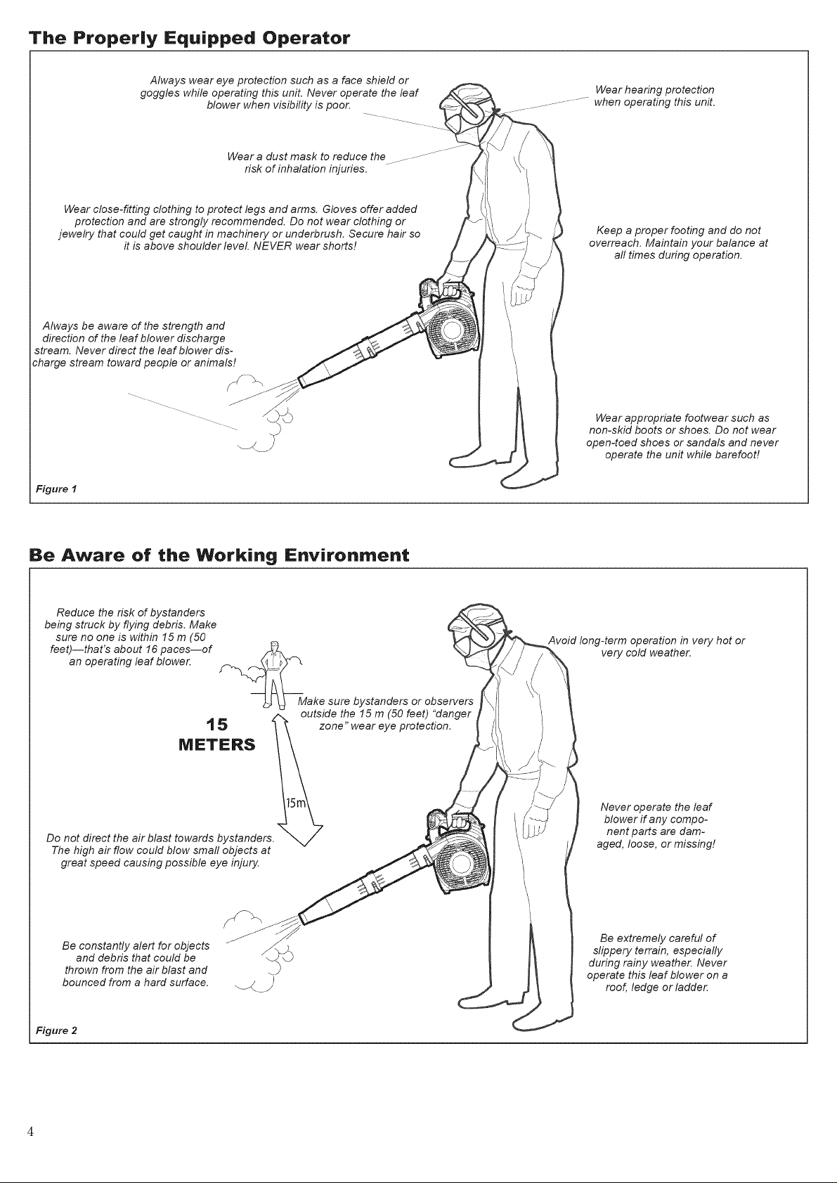
The Properly Equipped Operator
Always wear eye protection such as a face shield or
goggles while operating this unit. Never operate the leaf _ ......
blower when visibility is poor. ....... ---_-... ___.. ......
Wear a dust mask to reduce the *% _' \( \_
risk of inhalation injuries. \\! 1
Wear close-fitting clothing to protect legs and arms. Gloves offer added I }
protection and are strongly recommended. Do not wear clothing or ' 7%
jewelry that could get caught in machinery or underbrush. Secure hair so
Always be aware of the strength and
direction of the leaf blower discharge
stream. Never direct the leaf blower dis-
charge stream toward people or animals!
it is above shoulder level. NEVER wear shorts!
Wear hearing protection
when operating this unit.
Keep a proper footing and do not
J
overreach. Maintain your balance at
all times during operation.
\
Wear appropriate footwear such as
non-skid boots or shoes. Do not wear
open-toed shoes or sandals and never
operate the unit while barefoot]
Figure I
Be Aware of the Working Environment
Reduce the risk of bystanders
being struck by flying debris. Make
sure no one is within 15 m (50
feet)--that's about 16 paces--of
an operating leaf blower.
_Make sure bystanders or observers
15
METERS
Do not direct the air blast towards bystanders.
The high air flow could blow small objects at
great speed causing possible eye injury.
outside the 15 m (50 feet) "danger
zone" wear eye protection.
Avoid long-term operation in very hot or
very cold weather.
Never operate the leaf
blower if any compo-
nent parts are dam-
aged, loose, or missing!
Be constantly alert for objects
and debris that could be
thrown from the air blast and
bounced from a hard surface.
Figure 2
Be extremely careful of
slippery terrain, especially
during rainy weather. Never
operate this leaf blower on a
roof, ledge or ladder.
Page 5

Unit Description
Recoil/
Starter
Air Cleaner
Fuel
Primer
Bulb
Handle
\\\\\\
Throttle Limiter
Lever
_i--
Throttle Lever
Safety and Operation Information Labels:
Make sure all information labels are
undamaged and readable. Immediately
replace damaged or missing information
labels. New labels are available. Contact
Swisher Inc. at (800) 222-8183, or go to
www.swisherinc.com for assistance.
Ignition Switch
\
,,
Fuel Filler
Cap
Figure 3
Prier to Assembly
Using Figure 3 as a guide, familiarize
yourself with the leaf blower and its compo-
nents. Understanding the unit helps ensure
top performance, longer service life, and
safer operation.
Exhaust
Leafblower
Tub#_
Leaf blower
Fan _FipNozzle (Standard on E4-A4000
Optional on E4-A3000)
Before assembling the leaf blower, make
sure you have all required components.
11 Power unit and leaf blower assembly.
11 This Owner's/Operator's Manual
and a tool kit containing a reel
bag and a combination spark plug
wrench/screwdriver.
Leafblower Air
Carefully inspect all components for damage.
The terms "left", "left-hand", "LH"; "right",
"right-hand", and "RH"; "front" and "rear"
refer to directions as viewed by the opera-
tor during normal operation.
Specifications
Model. E4-A3000 E4-A4000
Dry Weight (without Leaf blower Tubes). 4.9 kg (10.8 lb.) 5.1 kg (11.2 lb.)
Dimensions (IxWxH) 896 x 255 x 373 mm ( 35 x 10 x 15 in.)
Engine type 4 cycle air-cooled gasoline engine, vertical cylinder
Bore & Stroke. 4 x 27mm (L3 x 1.1 in.) 38 x 30 mm (1.50 x 1.18 in.)
Displacement. 24.5 cm3(1.5 cu. in.) 34 cm :_ (2.07 cu. in.)
Max Output/min -1 0.8 kW!1.1hp @7,500 min -1 (rpm) 1.0 kW!1.4 hp @ 8,000 min l(rpm)
Fuel/oil ratio. 50:1 with IS()-L-EGD or JAS() FC class 2-cycle mixing oil*
Carburetor. Walbro rotary-type with primer bulb
Ignition. CDI (Capacitor Discharge Ignition)
Spark Plug. NGK CMRSH
Starting Recoil Starter
Stopping Slide Switch (Grounding type)
Fuel Tank Capacity 0.6 L (20.0 oz)
Exhaust. Spark Arrester Muffler
Air Filtration Dry Element
Specifications are subject to change without notice.
EPA EMssion Compliance Period** .............................................................................................................................................................................................. Category A
**Tile EPA emission compliance referred to on tile emission compliance label located on tile engine, indicates tile number of operating hours for which tile en-
gine has been shown to meet Federal emission requirements, Category C = 50 hours (Moderate), B = 125 hours (Intermediate) and A = 300 hours (Extended)
*Swisher E4 engine oil meets or exceeds these specifications and is recommended for all Swisher products 5
Page 6
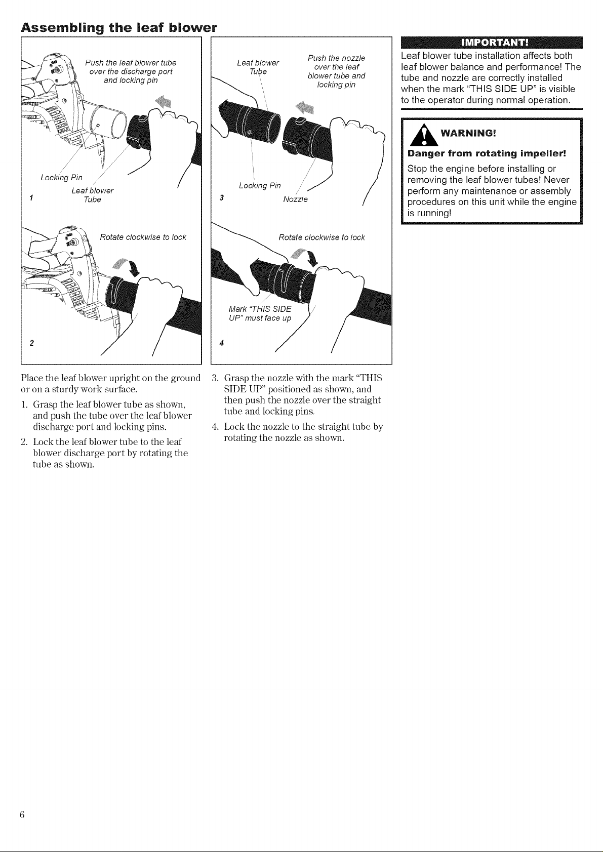
Assernb|ing the |ear b|ower
Push the leaf blower tube
Locking Pin //
Leaf blower
Tube
over the discharge port
and locking pin
Rotate clockwise to lock
Leaf blower
Tube
Locking Pin
j/
Mark "THIS SIDE /
UP" must face up
/
Nozzle
Rotate clockwise to lock
Push the nozzle
over the leaf
blower tube and
locking pin
Leaf blower tube installation affects both
leaf blower balance and performance! The
tube and nozzle are correctly installed
when the mark "THIS SIDE UP" is visible
to the operator during normal operation,
,_ WARRING!
Danger {rein rotating impeller!
Stop the engine before installing or
removing the leaf blower tubesg Never
perform any maintenance or assembly
procedures on this unit while the engine
is running!
Place the leaf blower upright on the ground
or on a sturdy work surface.
1. Grasp the leaf blower tube as shown,
and push the tube over the leaf blower
discharge port and locking pins.
2. Lock the leaf blower tube to the leaf
blower discharge port by rotating the
tube as shown.
3. Grasp the nozzle with the mark "THIS
SIDE UP" positioned as shown, and
then push the nozzle over the straight
tube and locking pins.
4. Lock the nozzle to the straight tube by
rotating the nozzle as shown.
Page 7
Mixing Fuel
CAUT|ON!
Never use any fuel containing more
than 10% alcohol by volume! Some
gasolines contain alcohol as an oxy-
genate! Oxygenated fuels may cause
increased operating temperatures.
Under certain conditions, alcohol-
based fuels may also reduce the lubri-
cating qualities of some mixing oils.
Generic oils and some outboard
motor oils may not be intended for
use in high-performance air cooled
2-cycle engines, and should never be
used in your Swisher engine!
CAUT|ON!
This engine is designed to oper-
ate on a 50:1 mixture consisting of
unleaded gasoline and a premium
2-cycle mixing oil only. Use of non-
approved mixing oils can lead to
excessive maintenance costs and/or
engine damage.
m Use only fresh, clean unleaded gasoline
with a pump octane rating of 87 or higher.
m Mix all fuel with a 2-cycle air-cooled
mixing oil that meets or exceeds
ISO-L-EGD and/or JASO FC classified
oils at 50:1 gasoline/oil ratio.
Example of 50:1 mixing quantities:
m 5 liters of gasoline to 0.1 liter mixing oil.
m i gallon of gasoline to 2.6 oz. mixing oil
Mix only enough fuel for your immediate
needs! If fuel must be stored longer than
30 days and Swisher E4 engine oil with
fuel stabilizer is not used, it should first
be treated with a fuel stabilizer such as
STA-BIL TM.
Swisher E4 engine oil is a registered JASO
FC classified oil and also meets or exceeds
ISO-L-EGD performance requirements.
Swisher E4 is recommended for use in all
Swisher low emissions engines and also
includes a fuel stabilizer.
WARNING!
Minimize the risk of fire!
m
STOP the engine before refueling.
ALWAYS allow the unit to cool
m
before refueling!
II ALWAYS store gasoline in a con-
tainer approved for flammable
liquids.
II Wipe all spilled fuel and move the
unit at least 3 m (10 feet) from the
fueling point before restarting!
II NEVER start or operate this unit if
there is a fuel leak.
m NEVER start or operate this unit if
the carburetor, fuel lines, fuel tank
and/or fuel tank cap are damaged.
m NEVER smoke or light any fires
near the unit or fuels!
m NEVER place any flammable mate-
rial near the engine muffle!!
m NEVER operate the engine without
the muffler and spark arrester in
place and properly functioning!
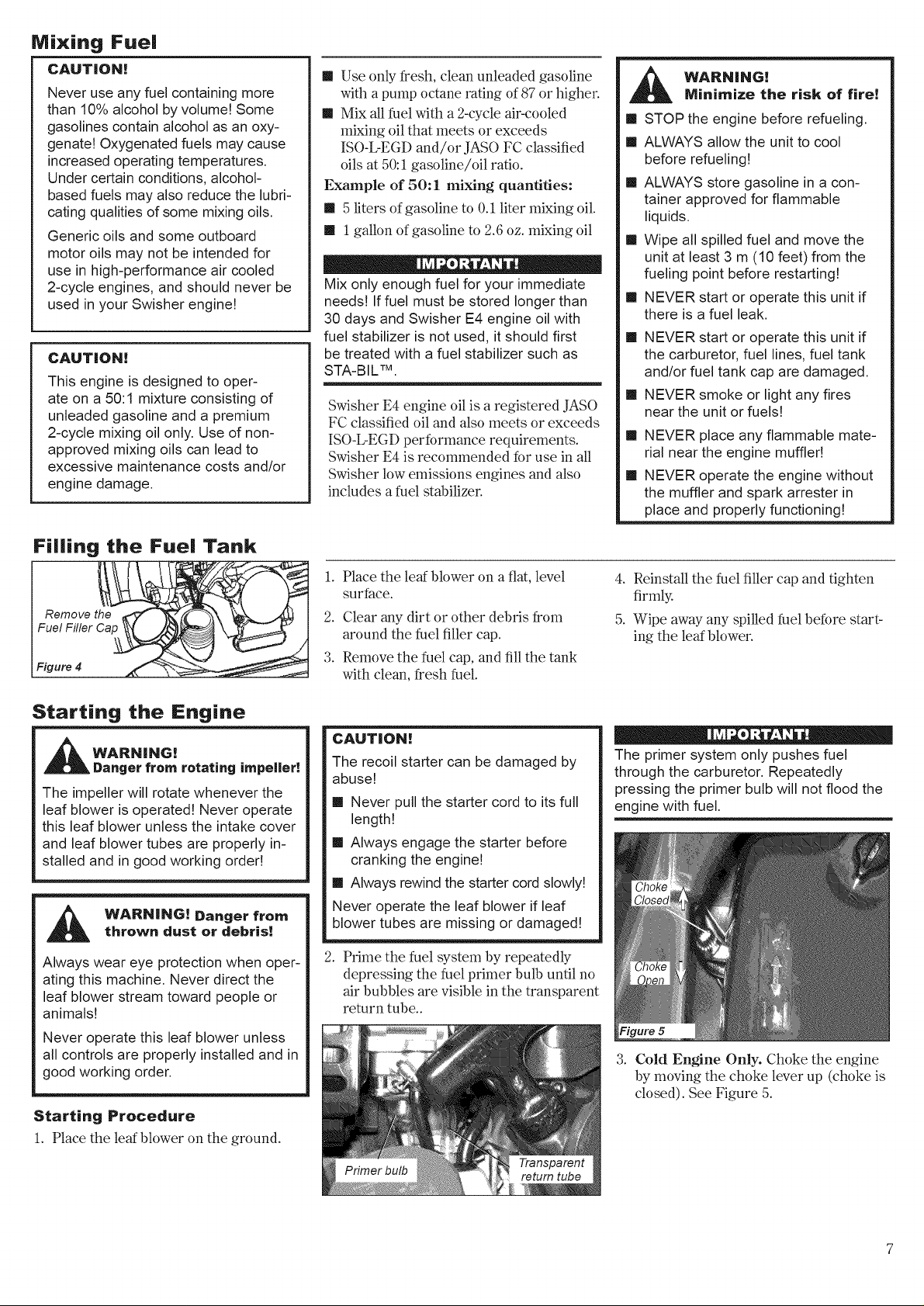
Filling the Fuel Tank
Starting the Engine
WARNING!
Danger from rotating impeller!
The impeller will rotate whenever the
leaf blower is operated! Never operate
this leaf blower unless the intake cover
and leaf blower tubes are properly in-
stalled and in good working order!
WARN|NG! Danger fromthrown dust or debris!
Always wear eye protection when oper-
ating this machine. Never direct the
leaf blower stream toward people or
animals!
Never operate this leaf blower unless
all controls are properly installed and in
good working order.
Starting Procedure
1. Place the leaf blower on the ground.
1.
Place the leaf blower on a flat, level
surface.
2.
Clear any dirt or other debris from
around the fuel filler cap.
3.
Remove the fuel cap, and fill the tank
with clean, fresh fuel.
CAUTION!
The recoil starter can be damaged by
abuse!
m Never pull the starter cord to its full
length!
m Always engage the starter before
cranking the engine!
m Always rewind the starter cord slowly!
Never operate the leaf blower if leaf
blower tubes are missing or damaged!
2. Prime the fuel system by repeatedly
depressing the fuel primer bulb until no
air bubbles are visible in the transparent
return tube..
4. Reinstall the fuel filler cap and tighten
firmly.
5. Wipe away any spilled fuel before start-
ing the leaf blower.
The primer system only pushes fuel
through the carburetor. Repeatedly
pressing the primer bulb will not flood the
engine with fuel.
Figure 5
3. Cold Engine Only. Choke the engine
by moving the choke lever up (choke is
closed). See Figure 5.
Page 8

Starting the Engine (continued)
Full Throttle
Idle
Figure 6
4. Slide the ignition switch to the 'T' (ON)
position, then depress the throttle lever
haK way and lock throttle by moving
throttle lock lever halfway down. See
Figure 6.
ON
Ignition
_ - Switch
Throttle
f Lever
7. As the starter engages, pull the starter
8. If necessary, repeat Steps 6 and 7 until
When The Engine Starts-
1. Open the choke (ifit is not already
2. If the engine does not continue to run,
3. Operate the throttle to reduce engine to
handle upward rapidly.
the engine starts.
open) by moving the choke lever down.
repeat the appropriate starting proce-
dures for a cold or warm engine.
idle speed until operating temperature is
reached (2-3 minutes).
Starting A Flooded Engine
1. Disconnect the spark plug lead, and
remove the spark plug (see page 11 for
procedures).
2. If the spark plug is fouled or is soaked
with fuel, clean or replace the plug as
required.
3. With the spark plug removed, open the
choke, put the throttle lever in the full
throttle position, then clear excess fuel
from the combustion chamber by crank-
ing the engine several times.
4. Install and tighten the spark plug, and
reconnect the spark plug lead.
5. Repeat the starting procedures for a
warm engine.
6. If the engine still fails to start or fire,
refer to the troubleshooting flow chart at
the end of this manual.
5. Hold the leaf blower firmly with your left
hand on the handle.
6. Using your right hand, pull the starter
handle slowly until you feel the starter
engage. See Figure 7.
Adjusting Engine |die Speed
|f The Engine Does Not Start-
Repeat the appropriate starting procedures
for warm or cold engine. If the engine still
will not start, follow the "Starting a Flooded
Engine" procedure.
WARN|NG! Never operate the
leaf blower unless all controls are prop-
erly installed and in good working order,
Never operate the leaf blower if the
cylinder cover is missing or damaged!
Ignition
Switch
__e Lever
Stopping The Engine
1. Cool the engine by allowing it to run at
idle for 2-3 minutes.
2. Slide the ignition switch towards the
rear to "O" (OFF). See Figure 8.
A clean and unrestricted airflow is essen-
tial to your leaf blower's engine perfor-
mance and durability! Before attempting
any carburetor adjustments, inspect and
clean the engine air filter as described on
page 10 of this manual,
Leaf blower tubes and the air cleaner must
be in place while adjusting engine idle!
Engine idle speed wilt also be affected if
the leaf blower tubes are blocked or incor-
rectly installed!
1. Place the unit on the ground and start
the engine, then allow it to idle 2-3 min-
utes until warm.
2. If a tachometer is available, the engine
idle speed should be final adjusted to 3000
(_+300)min-1(rpm). See Figure 9.
Idle Decrease
Adjustment
Screw
e1!
Figure 9
Idle Increase
Carburetor fuel mixture adjustments are pre-
set at factory on units with emission control
systems and cannot be serviced in the field.
Page 9

ThrotUe Control
The E4-A3000 and E4-A4000 are equipped
with a multi-function throttle control. The
"Cruise" function allows the operator to
use a thumb controlled lever for constant
speed use without using the throttle trigger.
This is useful for limiting the fatigue caused
from holding the throttle for extended
periods of time.
On the opposite side, a two position
"Limiter" control allows full engine speed
when set for "Turbo" or limits the throttle
to a pre-set engine speed when set to low
noise (dB) setting.
Cruise Function Using the right
thumb, push the throttle lock lever down
until the desired min-1(rpm) setting is
reached. See Figure 10.
Thumb
Control
Lever.
Throttle Limiter
The E4-A3000 and E4-A4000 have a throttle
limiter function that allows the operator to
pre-set the maximum engine speed. This is
useful for reducing the noise emitted by the
leaf blower in noise sensitive areas.
Setting Throttle Limiter:
For reduced noise setting, move the
throttle limiter located on the right side of
the throttle control to the dB setting. See
Figure 11.
Throttle Limiter
Lever \ Throttle Limiter
Turbo Setting ....--.. " Adjustment
3. With the engine running and while
depressing the throttle trigger, use a
small Phillips screw driver to turn the
adjustment screw clockwise to decrease
rain-1(rpm) and counter-clockwise to
increase until desired limited min -1
(rpm) is achieved.
4. Reinstall limiter adjustment plug.
Remove Iimiter
adjustment plug
k, /:_
I
Figure12 I
To bring RPM down to idle, push lever
back up into original position.
Using The Leaf blower
Operating Tips
In the hands of an experienced operatol;
the E4-A3000 and E4-A4000 can efficiently
move a wide variety of debris ranging from
grass clippings to gravel. As a general rule,
operate your leaf blower at the lowest throt-
tle setting required to get the job done:
m Use low throttle settings when clearing
lightweight materials from around lawns
or shrubbery.
Figure 11
Adjusting Throttle Limiter:
1. Remove the plug located at the top of
the throttle assembly. See Figure 12.
2. Move the throttle limiter lever to the
"dB" setting. See Figure 12.
m Use medium to higher throttle settings
to move grass or leaves from parking
lots or walkways.
m Use full throttle when moving heavy
loads such as dirt or snow.
With the throttle limiter adjusted to 7,000 min-1
(rpm), the E4-A3000 will have a sound level of
65 dB(A) measured at 15 m (50 feet).
With the throttle limiter adjusted to 6,500 min -1
(rpm), the E4-A4000 will have a sound level of
65 dB(A) measured at 15 m (50 feet).
" 0 " ,
Leaf blower noise increases at higher
throttle settings! Always use the lowest
throttle setting required to get the job
done!
Page 10

Maintenance
Maintenance, replacement or repair of
emission control devices and systems may
be performed by any repair establishment
or individual, However, warranty repairs
must be performed by a dealer or service
center authorized by Swisher. The use
of parts that are not equivalent in perfor-
mance and durability to authorized parts
may impair the effectiveness of the emis-
sion control system and may have a bear-
ing on the outcome of a warranty claim.
Air Filter
The E4 engine that powers your Swisher
model is a hybrid 4-stroke engine. As a
hybrid, the engine is lubricated by oilmixed
with the gasoline and air from the carburetor
that moves through and around the internal
parts of the engine in a similar way that a
Daily Maintenance
_ WARN|NG!
To reduce fire hazard, keep the engine
and muffler free of dirt, debris, and
leaves.
Prior to each workday, perform
the following:
m Remove all dirt and debris from leaf
blower exterior and the engine. Check
the cooling fins and air cleaner for clog-
ging and clean as necessary.
_ WARN|NG!
Before performing any maintenance,
repair or cleaning work on the unit,
make sure the engine is completely
stopped. Disconnect the spark plug
wire before performing service or
maintenance work.
2-stroke engine is lubricated. Without the
heavy duty 2-stage air filter equipped on all
E4 engines, dust and dirt could also move
through the engine, decreasing engine life,
increasing valve wear and the need for more
frequent valve adjustments. To keep your E4
CAUT|ON!
The engine is cooled by air drawn
into the air intake cover on the leaf
blower housing. The leaf blower fan
then pushes the cooling air through an
opening in the fan housing, forcing it
past the cylinder cooling fins. Failure to
keep the cooling system and its pas-
sages clear of debris will likely result in
engine overheating, a major cause of
serious engine problems that can lead
to failure.
_ WARN|NG!
Non-standard parts may not operate
properly with your unit and may cause
damage and lead to personal injury.
Using non-standard replacement parts could
invalidate your Swisher warranty.
engine strong and reliable, Swisher recom-
mends that you check and service the air fil-
ter as instructed in the 10-Hour Maintenance
section that follows.
m Inspect the engine, tank, and hoses
for possible fuel leaks, and repair as
necessary.
m Inspect the entire leaf blower for loose,
damaged, or missing components, and
repair as necessary.
m Carefully remove any accumulations of
dirt or debris from the muNer and fuel
tank. Dirt build-up in these areas can
lead to engine overheating, fire or pre-
mature weak
Every 10 Hours
(more frequently in dusty conditions)
1. Remove the air cleaner cover by loosen-
ing the thumb screw and lifting up. See
Figure 13A.
2. Remove and inspect the pre-filter. If the
pre-filter is torn or otherwise damaged,
replace it with a new one. See Figure 13B.
3. Clean the pre-filter with soap and water.
Let dry before reinstalling.
4. Inspect the air cleaner element. If the
element is damaged or distorted, replace
it with anew one. See Figure 13B.
5. Tap filter gently on a hard surface to
dislodge debris from element or use
compressed air from the inside to blow
debris out and away from the air filter
element.
Direct the air stream at the inside face of
the filter only!
6. Install the filter element, pre-filter and
cover in the reverse order of removal.
Pre-Fflter
Filter
Element
Figure 13B
CAUT|ON!
Never operate the leaf blower if the air
cleaner assembly is damaged or missing!
10
Page 11

Every 10/15 Hours
=
_ 0 Counter- clock-
0 6mm _ ,---, and check the gap at
(0.024 in. the electrode.
Figure 14 _t NGK CMR5H
wise to remove.
Clean the spark plug
Every 50 Hours
{more frequently if reduced per-
formance is noted)
INSPECTION Inspect the entire leaf
blower and tubes for damage, including
loose or missing components, and repair
as necessary.
m SPARK PLUG Replace the spark plug
with a NGK CMRSH (or equivalent),
gapped m 0.6mm (0.024 in.).
m FUEL FILTER Use a hooked wire to
extract the fuel filter from inside the fuel
tank. See Figure 15.
CAUT|ON!
Make sure you do not pierce the fuel
line with the end of the hooked wire.
The line is delicate and can be dam-
aged easily.
CAUT|ON!
Never allow dirt or debris to enter the
cylinder bore! Before removing the
spark plug, thoroughly clean the spark
plug and cylinder head areag
Allow the engine to cool before servic-
ing the spark plugf Cylinder threads
can be damaged by tightening or loos-
ening the spark plug while the engine
is hot!
II
Remove and replace the filter element.
Before reinstalling the new filter ele-
ment, inspect the condition of all the fuel
system components (fuel pick-up line,
fuel return line, tank vent line, tank vent,
fuel cap and fuel tank). If damage, split-
ting or deterioration is noted, the unit
should be removed from service until
it can be inspected or repaired. Contact
Swisher Inc. at (800) 222-
8183, or go to www.swisherinc.com for
assistance.
COOLING SYSTEM Use a wood or
II
plastic scraper and a soft brush to
remove dirt and debris from the cylin-
der fins and crankcase.
1. Use the spark plug wrench to remove
the spark plug. See Figure 14.
2. Clean and adjust the spark plug gap to
0.6mm (0.024 in.). If the plug must be
replaced, use a NGK CMR5H or equiva-
lent type plug of the correct heat range.
3. Install the spark plug finger-tight
in the cylinder head, then tighten it
firmly with the spark plug wrench. If a
torque wrench is available, torque the
spark plug to 16.7-18.6 Nm 048-165
inch-pounds)
I
Hooked
Filter
Fuel Tank
=igure 15
139/150-Hour Maintenance
Maintenance after first 139-
hours, then every 150-hours
thereafter,
m Combustion chamber should be decal'-
bonized, and the valve clearance should
be adjusted. It is highly recommended
that this is done by a Swisher-trained
service technician.
m Replace the spark plug annually: Use
only NGK CMR5H or equivalent resis-
tor type spark plug of the correct heat
range. Set spark plug electrode gap to
0.6ram (0.024 in.).
The NGK CMR5H also meets the require-
ments for electro magnetic compliance
(EMC).
Valve Adjustment
1. Remove cylinder cover, rocker arm cover,
and set piston at TDC-compression.
Rotate the crankshaft while observing
the piston through the spark plug open-
ing. When the piston is at the top of the
compression stroke (TDC), the valves
can be adjusted.
CAUT|ON!
II Performing a valve adjustment
incorrectly may cause hard starting
and/or can damage the engine.
II If you are unfamiliar with this engine
or uncomfortable with this proce-
dure, consult with an authorized E4
Swisher servicing dealer.
2. Ix_osen adjuster locknut so that the 2.5
mm Allen socket head adjustment screw
can turn freely.
3. Insert 0.10 mm (0.004") feeler gauge
between valve stem tip and rocker arm.
4. Turn adjustment screw (clockwise =
tighter, counter-clockwise = looser) until
feeler gauge is almost snug. Back off
just enough to allow gauge to slip out
with limited resistance.
11
Page 12

139/150-Hour Maintenance (continued)
6. Turn engine over several times, and
returnthe m TDC-compression.
Recheck with proper feeler gauge m
make sure clearance adjustment did not
change as a result of tightening the lock-
nut. Readjust as necessary.
7. Replace rocker arm cover gasket to
assure proper sealing and install cover.
5. While holding the adjustment screw in
place with the Allen driver, tighten the
locknut with a wrench.
Spark Arrester Maintenance
_ WARN|NG!
blower with a damaged or missing
muffler or spark arrested Operating
with missing or damaged exhaust
components is a fire hazard, and
can also damage your hearing!
Never operate this leaf
Hard starting or a gradual loss of perfor-
mance can be caused by carbon deposits
lodged in the spark arrester screen. For
maximum perMrmance, the spark attester
screen should be periodically cleaned as
follows. See Figure 16.
Arrester Screen
Cover
=igure 16
1. Remove engine cover to expose muffler.
Remove the spark arrester from the
muffler. The arrester is press-fit in place;
there are three screws to remove.
Arrester
Screen
Muffler
If a new gasket is not available and/or the
old gasket is not damaged, the old gasket
may be reused. Never use cracked or
damaged gaskets!
.
Use a plastic scraper or wire brush
to remove carbon deposits from the
arrester screen and wipe clean exhaust
base.
3. Inspect the screen carefully, and replace
any screen that has been perforated, dis-
torted, or is otherwise unserviceable.
4. Press the spark arrester into the
exhaust base.
If you note excessive carbon buildup, con-
sult with an authorized E4 Swisher servic-
ing dealer. Contact Swisher Inc. at (800)
222-8183, or go m www.swisherinc.com.
Long Term Storage
Whenever the unit will not be
used for 30 days or longer, use
the following procedures to prepare it for
storage:
Clean external parts thoroughly.
m Drain all the fuel from the fuel tank.
All stored fuels should be stabilized with
a fuel stabilizer such as STA-BIL TM if
Swisher E4 Engine Oil with fuel stabilizer
is not used.
To remove the remaining fuel from the
fuel lines and carburetor and with the fuel
drained from the fuel tank.
1. Prime the primer bulb until no more fuel
is passing through.
2. Start and run the engine until it stops
running.
3. Repeat steps i and 2 until the engine will
no longer start.
CAUT|ON!
Gasoline stored in the carburetor for
extended periods can cause hard start-
ing, and could also lead to increased
service and maintenance costs.
m Remove the spark plug and pour
about 10 cm :_(1/4 oz.) of 2-cycle mixing
oil into the cylinder through the spark
plug hole. Slowly pull the recoil starter
2 or 3times so oil will evenly coat the
interior of the engine. Reinstall the spark
plug.
m Before storing the unit, repair or replace
any worn or damaged parts.
m Remove the air cleaner element from the
unit and clean it as outlined on page 10.
m Store the unit in a clean, dust-free area.
12
Page 13

Troubleshooting Guide
What To Check
Does the engine crank?
YES
Good compression?
YES !
Does the tank contain fresh
fuel of the proper grade?
YES
isfuel visible and moving in
the return line when priming?
Possible Cause
Faulty recoilstarter.
Fluid in the crankcase.
Internal damage.
Loosespark plug.
Excess wear on cylinder,piston, rings.
Fuel incorrect, stale, or contaminated;
mixture incorrect.
Checkfor clogged fuel filterand/or vent.
Priming pump not functioning properly.
Remedy
Consult with an authorizedservicing dealer.
Tighten and re-test.
Consult with an authorized servicing dealer.
Refill with clean, fresh unleaded
gasoline with a pump octane of 87 or
higher, mixed with a 2-cycle air cooled
mixing oil that meetsor exceeds ISO-L-
EGD and/or JASO FC classifiedoils at 50:1
gasoline/oil ratio.
Replace fuel filter orvent as required.
Re-start.
Consult with an authorized
servicing dealer.
YES
isthere spark at the spark
plug wire terminal?
YES
Check the spark plug.
The ignition switch is in"O"(OFF) position.
Shorted ignition ground.
Faulty ignition unit.
If the plug iswet, excess fuel may be in the
cylinder.
The plug is fouled or improperly gapped.
The plug is damaged internally or of the
wrong size.
Move switch to 'T'(ON) position
and re-start.
Consult with an authorized
servicing dealer.
Crank the engine with the plug removed,
re-install the plug and re-start.
Clean and re-gap the plug to
0.6 mm (0.024 in.). Re-start.
Replace the plug with a NGK CMR5H or
equivalent resistortype spark plug of the
correct heat range. Set spark plug electrode
gap to 0.6mm (0.024 in.).
13
Page 14
Troubleshooting Guide (continued)
What To Check
isthe engine overheating?
Engine is roughat all
speeds. May also have
black smoke and!or
unburned fuel at the
exhaust.
Possible Cause
Operator is overworking the unit.
Carburetor mixture istoo lean.
Improper fuel ratio.
Fallen leaves or debris on intake cover.
Fan, fan cover, cylinder fins dirty
or damaged.
Carbon deposits on the piston or
in the muffler.
Clogged air cleaner element.
Loose or damaged spark plug.
Air leakage or clogged fuel line.
Remedy
Use alower throttle setting.
Consult with an authorized
servicing dealer.
Refill with clean, fresh unleaded gasoline
with apump octane of 87 or higher, mixed
with apremium 2-cycle air cooled mixing oil
or equivalentat a 50:1 gasoline ratio.
Clean the intake cover.
Clean, repairor replace as necessary.
Consult with an authorized
servicing dealer.
Service the air cleaner element.
Tighten or replace the spark plug.
See page 11.
Repair or replacefuel filter and/or
fuel line.
Engine is knocking.
Water in the fuel.
Piston seizure.
Faulty carburetor and/ordiaphragm.
Overheating condition.
Improper fuel.
Carbon deposits in the
combustion chamber.
Replace thefuel. See page 7.
Consult with an authorized
servicing dealer.
See above.
Check fuel octane rating; check for
presence of alcohol in the fuel. See page 7.
Refuel as necessary.
Consult with an authorized
servicing dealer.
14
Page 15

Troubleshooting Guide (continued)
Symptom
Poor acceleration.
Engine stops abruptly.
Possible Cause
Clogged air filter.
Clogged fuel filter.
Leanfuel/air mixture.
Idlespeed set too low.
Ignition switch turned off.
>
Fueltank empty.
Clogged fuel filter.
Water inthe fuel.
Shorted spark plug or loose terminal.
Ignitionfailure.
Remedy
Clean the air filter.
Replace the fuel filter.
Consultwith an authorized
servicing dealer.
Adjust: 3000 (_+300)min-1(rpm).
Reset the switch and re-start.
Refuel. See page 7.
Replace fuel filter.
Drain; replace with cleanfuel.
See page 7.
Clean or replace spark plug, tighten the
terminal.
Replace the ignitionunit.
Engine difficult to shut off.
Excessive vibration.
Engine overspeeding.
Pistonseizure.
Ground (stop)wire isdisconnected, or
switch is defective.
Overheating due to incorrectspark plug.
Overheated engine.
Debris build-up in impeller.
Looseor damaged impeller.
Looseor damaged engine mounts.
Leafblower intakeor discharge ports or
tubes areclogged with debris.
Impeller blades are missingor damaged.
Consultwith an authorized
servicing dealer.
Testand replace as required.
Idle engine until cool. Clean and regap the
plug to 0.6 mm (0.024 in.). Correct plug:
NGK CMR5H or equivalent resistor type
spark plug d the correct range.
Idle engine until cool.
Clean debrisfrom impelleras required.
Inspect and replace impeller as required.
Tighten or replace engine mounts as
required.
Inspect and remove debris.
Consultwith an authorized
servicing dealer.
15
Page 16
Emission System Warranty Statement (Administered by Shindaiwa inc.)
Your Warranty Rights and Obligations
The California Air Resources Board, the U.S. Environmental
Protection Agency and Shindaiwa Corporation are pleased to
explain the exhaust and evaporative emission control system
warranty on your new small off-road (non-road) engine.
In California, new small off-road engines must be designed,
built, and equipped to meet the State's stringent anti-smog stan-
dards. In other states, new 1997 and later non-road engines must
meet the Federal EPA's stringent anti-smog standards.
Shindaiwa Corporation must warrant the emission control sys-
tem on your small off-road engine for the periods of time listed
below, provided there has been no abuse, neglect, or improper
maintenance of your small off-road engine.
Your engine exhaust and evaporative emission control system
includes parts such as the carburetor, fuel tank, the ignition sys-
tem and, if equipped, the catalytic converter. These components
are specifically listed below.
Where a warrantable condition exists, Shindaiwa Corporation
will repair your small off-road engine at no cost to you including
diagnosis, parts, and labon
Manufacturer's Warranty Coverage
When sold within the U.S., this engine's emission control
system is warranted for a period of two (2) years from the date
this product is first delivered to the original retail purchaser.
During the warranty period, Shindaiwa Corporation will, at
their option, repair or replace any defective emission-related
component on this engine. During the original Warranty Period,
these Warranty Rights are automatically transferable to subse-
quent owners of this product.
What is Covered by this Warranty
1. Carburetor Internal Components
m Throttle Valve, Needle, Jet, Metering Diaphragm
2. Fuel Tank
3. Ignition System Components
m Ignition Coil
m Flywheel Rotor
4. Catalytic Converter (if originally equipped)
The emission control system for your particular Shindaiwa
Corporation engine may also include certain related hoses and
connectors.
Owners Warranty Responsibilities
As the small off-road engine owner, you are responsible for
the performance of the required maintenance listed in this own-
ers manual. Shindaiwa Corporation recommends that you retain
all receipts covering maintenance on your small off-road engine,
but Shindaiwa Corporation cannot deny warranty solely for the
lack of receipts or for your failure to ensure the performance of
all scheduled maintenance.
As the small off-road engine owner, you should be aware,
however, that Shindaiwa Corporation may deny you warranty
coverage if your small off-road engine or a part has failed due to
abuse, neglect, improper maintenance, or unapproved modifica-
tions.
You are responsible for presenting your small off-road engine
to an authorized Shindaiwa Corporation Dealer as soon as a
problem exists. The warranty repairs should be completed in a
reasonable amount of time, not to exceed 30 days.
If you have any questions regarding your warranty rights and
responsibilities, you should contact a Shindaiwa Corporation cus-
tomer service representative or your local Shindaiwa Dealer.
Consequential Damages
In the event that other component parts of this product
are damaged by the failure of a warranted part, Shindaiwa
Corporation will repair or replace such component parts at no
charge to you.
What is Not Covered
m Failures caused by abuse, neglect, or improper maintenance
procedures.
B Failures caused by the use of modified or non-approved parts
or attachments.
This Warranty is Administered by:
Shindaiwa Corporation
11975 SW Herman Road
Tualatin, OR 97062
(503) 692-3070
Swisher
EO. Box 67
Warrensburg, MO 64093.
16
Part Number 68917-94o10
Rev. 12/2007
 Loading...